EP4309853A2 - Chirurgisches system - Google Patents
Chirurgisches system Download PDFInfo
- Publication number
- EP4309853A2 EP4309853A2 EP23213956.8A EP23213956A EP4309853A2 EP 4309853 A2 EP4309853 A2 EP 4309853A2 EP 23213956 A EP23213956 A EP 23213956A EP 4309853 A2 EP4309853 A2 EP 4309853A2
- Authority
- EP
- European Patent Office
- Prior art keywords
- incised
- motion center
- center position
- initial
- surgical instrument
- Prior art date
- Legal status (The legal status is an assumption and is not a legal conclusion. Google has not performed a legal analysis and makes no representation as to the accuracy of the status listed.)
- Pending
Links
Images


Classifications
-
- A—HUMAN NECESSITIES
- A61—MEDICAL OR VETERINARY SCIENCE; HYGIENE
- A61B—DIAGNOSIS; SURGERY; IDENTIFICATION
- A61B34/00—Computer-aided surgery; Manipulators or robots specially adapted for use in surgery
- A61B34/30—Surgical robots
- A61B34/37—Leader-follower robots
-
- A—HUMAN NECESSITIES
- A61—MEDICAL OR VETERINARY SCIENCE; HYGIENE
- A61B—DIAGNOSIS; SURGERY; IDENTIFICATION
- A61B34/00—Computer-aided surgery; Manipulators or robots specially adapted for use in surgery
- A61B34/30—Surgical robots
- A61B34/35—Surgical robots for telesurgery
-
- A—HUMAN NECESSITIES
- A61—MEDICAL OR VETERINARY SCIENCE; HYGIENE
- A61B—DIAGNOSIS; SURGERY; IDENTIFICATION
- A61B90/00—Instruments, implements or accessories specially adapted for surgery or diagnosis and not covered by any of the groups A61B1/00 - A61B50/00, e.g. for luxation treatment or for protecting wound edges
- A61B90/06—Measuring instruments not otherwise provided for
-
- A—HUMAN NECESSITIES
- A61—MEDICAL OR VETERINARY SCIENCE; HYGIENE
- A61B—DIAGNOSIS; SURGERY; IDENTIFICATION
- A61B90/00—Instruments, implements or accessories specially adapted for surgery or diagnosis and not covered by any of the groups A61B1/00 - A61B50/00, e.g. for luxation treatment or for protecting wound edges
- A61B90/08—Accessories or related features not otherwise provided for
-
- B—PERFORMING OPERATIONS; TRANSPORTING
- B25—HAND TOOLS; PORTABLE POWER-DRIVEN TOOLS; MANIPULATORS
- B25J—MANIPULATORS; CHAMBERS PROVIDED WITH MANIPULATION DEVICES
- B25J3/00—Manipulators of leader-follower type, i.e. both controlling unit and controlled unit perform corresponding spatial movements
-
- A—HUMAN NECESSITIES
- A61—MEDICAL OR VETERINARY SCIENCE; HYGIENE
- A61B—DIAGNOSIS; SURGERY; IDENTIFICATION
- A61B34/00—Computer-aided surgery; Manipulators or robots specially adapted for use in surgery
- A61B34/30—Surgical robots
- A61B2034/301—Surgical robots for introducing or steering flexible instruments inserted into the body, e.g. catheters or endoscopes
-
- A—HUMAN NECESSITIES
- A61—MEDICAL OR VETERINARY SCIENCE; HYGIENE
- A61B—DIAGNOSIS; SURGERY; IDENTIFICATION
- A61B34/00—Computer-aided surgery; Manipulators or robots specially adapted for use in surgery
- A61B34/30—Surgical robots
- A61B2034/302—Surgical robots specifically adapted for manipulations within body cavities, e.g. within abdominal or thoracic cavities
-
- A—HUMAN NECESSITIES
- A61—MEDICAL OR VETERINARY SCIENCE; HYGIENE
- A61B—DIAGNOSIS; SURGERY; IDENTIFICATION
- A61B90/00—Instruments, implements or accessories specially adapted for surgery or diagnosis and not covered by any of the groups A61B1/00 - A61B50/00, e.g. for luxation treatment or for protecting wound edges
- A61B90/06—Measuring instruments not otherwise provided for
- A61B2090/061—Measuring instruments not otherwise provided for for measuring dimensions, e.g. length
-
- A—HUMAN NECESSITIES
- A61—MEDICAL OR VETERINARY SCIENCE; HYGIENE
- A61B—DIAGNOSIS; SURGERY; IDENTIFICATION
- A61B90/00—Instruments, implements or accessories specially adapted for surgery or diagnosis and not covered by any of the groups A61B1/00 - A61B50/00, e.g. for luxation treatment or for protecting wound edges
- A61B90/06—Measuring instruments not otherwise provided for
- A61B2090/067—Measuring instruments not otherwise provided for for measuring angles
-
- A—HUMAN NECESSITIES
- A61—MEDICAL OR VETERINARY SCIENCE; HYGIENE
- A61B—DIAGNOSIS; SURGERY; IDENTIFICATION
- A61B90/00—Instruments, implements or accessories specially adapted for surgery or diagnosis and not covered by any of the groups A61B1/00 - A61B50/00, e.g. for luxation treatment or for protecting wound edges
- A61B90/08—Accessories or related features not otherwise provided for
- A61B2090/0807—Indication means
Definitions
- the present invention relates to a surgical system.
- a system including a manipulator used in surgery is conventionally known (see PTLs 1 and 2, for example).
- a surgical instrument is attached to a tip end portion of the manipulator (arm).
- the surgical instrument includes a long and thin rod-shaped shaft.
- a treatment tool such as forceps, is attached to a tip end of the shaft and is inserted into a body of a patient through an incised part of the patient.
- the manipulator is controlled by remote control of an operator. Thus, the position and posture of the surgical instrument can be changed.
- a motion center position of the surgical instrument when the position and posture of the surgical instrument is changed is located on a body surface of the patient or in the vicinity of the body surface. Therefore, for example, in thoracic surgery, when the surgical instrument is inserted between bones, such as ribs, the surgical instrument is manipulated such that the shaft of the surgical instrument does not contact the bones during the surgery. On this account, a movable range of a tip end of the surgical instrument is small, and this makes it difficult to perform the surgery.
- the present invention was made to solve the above problem, and an object of the present invention is to provide a surgical system capable of securing a large movable range of a tip end of a surgical instrument even when the surgical instrument is inserted into a narrow region, for example, a region between bones, such as ribs.
- a surgical system includes: a manipulator configured such that a tip end portion thereof moves relative to a base end portion thereof in a three-dimensional space; a surgical instrument including a rod-shaped shaft coupled to the tip end portion of the manipulator and a treatment tool provided at a tip end portion of the shaft; a manipulation input portion to which an operator inputs a command regarding a position and posture of the surgical instrument; a control apparatus configured to control an operation of the manipulator based on the command input to the manipulation input portion; and a motion center position setting portion configured to set a desired position in the control apparatus as a motion center position of the surgical instrument inserted into an incised part of a patient, the desired position being located in an inner part under a body surface of the patient, wherein the control apparatus is configured to control the operation of the manipulator such that in a case where the control apparatus controls the operation of the manipulator based on the command, input to the manipulation input portion, after the surgical instrument is inserted into a body of the
- the present invention is configured as explained above and has an effect of being able to provide a surgical system capable of securing a large movable range of a tip end of a surgical instrument even when the surgical instrument is inserted into a narrow region, for example, a region between bones, such as ribs.
- a surgical system includes: a manipulator configured such that a tip end portion thereof moves relative to a base end portion thereof in a three-dimensional space; a surgical instrument including a rod-shaped shaft coupled to the tip end portion of the manipulator and a treatment tool provided at a tip end portion of the shaft; a manipulation input portion to which an operator inputs a command regarding a position and posture of the surgical instrument; a control apparatus configured to control an operation of the manipulator based on the command input to the manipulation input portion; and a motion center position setting portion configured to set a desired position in the control apparatus as a motion center position of the surgical instrument inserted into an incised part of a patient, the desired position being located in an inner part under a body surface of the patient, wherein the control apparatus is configured to control the operation of the manipulator such that in a case where the control apparatus controls the operation of the manipulator based on the command, input to the manipulation input portion, after the surgical instrument is inserted into a body of the patient through the incised part
- the motion center position of the surgical instrument is set in (the inner part of) the body of the patient, instead of the body surface of the patient or near the body surface of the patient.
- the motion center position setting portion may include a motion center position setting manipulation portion configured to, when the surgical instrument is inserted into the body of the patient through the incised part, and a predetermined reference point of the surgical instrument is located at the desired position in the body, perform an operation of setting the position as the motion center position in the control apparatus.
- the surgical system may further include: an initial incised position setting portion configured to set a position of the incised part on the body surface of the patient as an initial incised position in the control apparatus; and a warning device configured to output a warning to the operator when the shaft is displaced from the initial incised position, and a predetermined condition is satisfied in a case where the control apparatus controls the operation of the manipulator after the surgical instrument is inserted into the body of the patient through the incised part, and the surgical instrument is arranged with the shaft passing through the motion center position.
- an initial incised position setting portion configured to set a position of the incised part on the body surface of the patient as an initial incised position in the control apparatus
- a warning device configured to output a warning to the operator when the shaft is displaced from the initial incised position, and a predetermined condition is satisfied in a case where the control apparatus controls the operation of the manipulator after the surgical instrument is inserted into the body of the patient through the incised part, and the surgical instrument is arranged with
- the motion center position setting portion may include: an initial incised position setting portion configured to set a position of the incised part on the body surface of the patient as an initial incised position in the control apparatus; and a calculating portion configured to calculate a position located away from the initial incised position by a predetermined distance in a predetermined direction and set the position as the motion center position in the control apparatus.
- the surgical system may further include a warning device configured to output a warning to the operator when the shaft is displaced from the initial incised position, and a predetermined condition is satisfied in a case where the control apparatus controls the operation of the manipulator after the surgical instrument is inserted into the body of the patient through the incised part, and the surgical instrument is arranged with the shaft passing through the motion center position.
- a warning device configured to output a warning to the operator when the shaft is displaced from the initial incised position, and a predetermined condition is satisfied in a case where the control apparatus controls the operation of the manipulator after the surgical instrument is inserted into the body of the patient through the incised part, and the surgical instrument is arranged with the shaft passing through the motion center position.
- the predetermined condition may be a condition in which a distance between the initial incised position and a position located away from the motion center position on a central axis of the current shaft by a distance between the initial incised position and the motion center position is not less than a predetermined value.
- the predetermined condition is a condition in which an approximate value is not less than a predetermined value, the approximate value being calculated as an approximate value of a distance between a center position of the current incised part and the initial incised position.
- the predetermined condition may be a condition in which a distance between the initial incised position and an intersecting position is not less than a predetermined value, the intersecting position being calculated as a position where a central axis of the current shaft intersects with a flat plane perpendicular to a vector, the vector passing through the initial incised position and extending from the motion center position toward the initial incised position.
- the predetermined condition is a condition in which an approximate value is not less than a predetermined value, the approximate value being calculated as an approximate value of a distance between a center position of the current incised part and the initial incised position.
- the initial incised position setting portion may include an initial incised position setting manipulation portion configured to, when the surgical instrument is inserted into the body of the patient through the incised part, and a predetermined reference point of the surgical instrument is located at a position of the incised part on the body surface of the patient, perform an operation of setting the position as the initial incised position in the control apparatus.
- the surgical system may further include a warning device configured to output a warning to the operator when an angle formed by a vector indicating a direction of a central axis of the shaft when the motion center position is set and a vector indicating a direction of the central axis of the current shaft is not less than a predetermined angle in a case where the control apparatus controls the operation of the manipulator after the surgical instrument is inserted into the body of the patient through the incised part, and the surgical instrument is arranged with the shaft passing through the motion center position.
- a warning device configured to output a warning to the operator when an angle formed by a vector indicating a direction of a central axis of the shaft when the motion center position is set and a vector indicating a direction of the central axis of the current shaft is not less than a predetermined angle in a case where the control apparatus controls the operation of the manipulator after the surgical instrument is inserted into the body of the patient through the incised part, and the surgical instrument is arranged with the shaft passing through the motion center position.
- the motion center position may be defined between adjacent bones in the body of the patient.
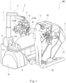
- Fig. 1 is a schematic diagram showing one example of an entire configuration of a surgical system according to an embodiment of the present invention.
- Fig. 2 is a side view showing one example of the configuration of a positioner of a patient-side apparatus.
- Fig. 3 is a schematic diagram showing one example of the configuration of a manipulator (arm) to which a surgical instrument of the patient-side apparatus is attached.
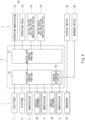
- Fig. 4 is a block diagram showing a schematic configuration of the surgical system.
- a surgical system 100 is a system by which an operator O, such as a doctor, performs an endoscope surgery for a patient Q by using a manipulating apparatus 2 to manipulate a patient-side apparatus 1, like a robot assisted surgery, a robot remote surgery, etc.
- the surgical system 100 includes the patient-side apparatus 1, the manipulating apparatus 2, and a control apparatus 6.
- the manipulating apparatus 2 is arranged away from the patient-side apparatus 1, and the patient-side apparatus 1 is remotely controlled by the manipulating apparatus 2.
- the manipulating apparatus 2 transmits to the control apparatus 6 a manipulate signal corresponding to the manipulation.
- the control apparatus 6 receives the manipulate signal transmitted from the manipulating apparatus 2 and operates the patient-side apparatus 1 based on the manipulate signal.
- the manipulating apparatus 2 constitutes an interface between the surgical system 100 and the operator O and is an apparatus configured to manipulate the patient-side apparatus 1.
- the manipulating apparatus 2 is provided beside an operating table 111 in an operating room, away from the operating table 111, or outside the operating room.
- the manipulating apparatus 2 includes: a manipulation input portion 50 to which the operator O inputs a manipulation command; and a display device 55 configured to display an image taken by an endoscope 41.
- the manipulation input portion 50 includes an operation manipulator 51, an operation pedal 52, and the like. While visually confirming an affected part on the display device 55, the operator O manipulates the manipulation input portion 50 to input the manipulation command to the manipulating apparatus 2.
- the manipulation command input to the manipulating apparatus 2 is transferred as the manipulate signal to the control apparatus 6 through a wire or wirelessly.
- the manipulating apparatus 2 includes an initial incised position setting manipulation portion (initial incised position setting portion) 53, a motion center position setting manipulation portion (motion center position setting portion) 54, and a warning device 56, which will be described later.
- the patient-side apparatus 1 constitutes an interface between the surgical system 100 and the patient Q.
- the patient-side apparatus 1 is arranged beside the operating table 111 on which the patient Q lies in the operating room.
- the patient-side apparatus 1 includes: a positioner 7; a platform 5 attached to a tip end portion of the positioner 7; a plurality of patient-side manipulators 3 (hereinafter referred to as “arms 3") detachably attached to the platform 5; the endoscope 41 attached to a tip end portion of an arm 3Athat is one of the plurality of arms 3; and surgical instruments 42 (hereinafter referred to as “instruments 42”) detachably attached to tip end portions of arms 3B that are the remaining ones of the plurality of arms 3.
- the positioner 7 and the platform 5 are covered with a sterile drape 9.
- the patient-side apparatus 1 includes, for example, four arms 3 that are one arm 3A to which the endoscope 41 is attached and three arms 3B to which the respective instruments 42 are attached. It should be noted that Fig. 4 shows only three arms 3.
- the positioner 7 is basically a horizontal articulated robot and includes: a base 70 placed on a floor of the operating room; a lifting shaft 72; a swinging arm 71 coupling the base 70 and a base end portion of the lifting shaft 72; and a horizontal arm 73 coupled to a tip end portion of the lifting shaft 72.
- the platform 5 is coupled to a tip end portion of the horizontal arm 73.
- the base 70 is, for example, a brake-equipped cart.
- the base 70 can be moved to a desired position and stopped thereat.
- a base end portion of the swinging arm 71 is coupled to the base 70 through a rotational joint J71.
- the rotational joint J71 By the operation of the rotational joint J71, the swinging arm 71 rotates (swings) about a horizontal rotation axis defined at the base 70.
- the base end portion of the lifting shaft 72 is coupled to a tip end portion of the swinging arm 71 through a rotational joint J72.
- the lifting shaft 72 includes: a tubular member 72a; a hollow shaft member 72b inserted into the tubular member 72a so as to be able to advance and retreat in a vertical direction; and a translational joint J73 coupling these members (72a and 72b).
- a translational joint J73 coupling these members (72a and 72b).
- the horizontal arm 73 includes: first and second links 74 and 75 extending horizontally; and a wrist link 76 coupled to a tip end portion of the second link 75.
- the platform 5 is connected to a tip end portion of the wrist link 76.
- Abase end portion of the first link 74 is coupled to a tip end portion of the lifting shaft 72 through a rotational joint J74.
- the rotational joint J74 By the operation of the rotational joint J74, the first link 74 rotates about a vertical rotation axis defined at the tip end portion of the lifting shaft 72.
- a tip end portion of the first link 74 is coupled to a base end portion of the second link 75 through a rotational joint J75.
- the rotational joint J75 By the operation of the rotational joint J75, the second link 75 rotates about a vertical rotation axis defined at the tip end portion of the first link 74.
- a tip end portion of the second link 75 is coupled to a base end portion of the wrist link 76 through a rotational joint J76.
- the wrist link 76 rotates about a horizontal rotation axis defined at the tip end portion of the second link 75.
- the wrist link 76 in a steady state extends vertically, and the platform 5 connected to the tip end portion of the wrist link 76 is held in a horizontal posture.
- the platform 5 serves as a "hub” that is a base of the plurality of arm 3.
- the arms 3 are detachably attached to the platform 5.
- the arms 3 can be detached from the platform 5 and subjected to a cleaning treatment and a sterilization treatment.
- the positioner 7 and the platform 5 constitute an arm support S movably supporting the plurality of arms 3. It should be noted that the arm support S is only required to include at least the platform 5.
- the arm support S may be constituted by the platform 5 supported by a linear motion rail, a lifting device, a bracket attached to a ceiling or a wall, or the like instead of the positioner 7.
- the plurality of arms 3 may be different in configuration from one another. Individual identification information is given to each arm 3.
- Fig. 3 shows a schematic configuration of one of the plurality of arms 3 included in the patient-side apparatus 1.
- the arm 3 includes: a first arm portion 30; and a second arm portion 35 coupled to a tip end portion of the first arm portion 30.
- the arm 3 is configured such that a tip end portion thereof can move relative to a base end portion thereof in a three-dimensional space.
- the arm 3 is configured such that, for example, the tip end portion thereof has six degrees of freedom in terms of the position and posture thereof.
- the first arm portion 30 includes: a base 80 detachably attached to the platform 5; and first to sixth links 81 to 86 sequentially coupled to one another from the base 80 to the tip end portion. More specifically, a base end portion of the first link 81 is coupled to a tip end portion of the base 80 through a twisting joint J31. Abase end portion of the second link 82 is coupled to a tip end portion of the first link 81 through a twisting joint J32. A base end portion of the third link 83 is coupled to a tip end portion of the second link 82 through a bending joint J33. A base end portion of the fourth link 84 is coupled to a tip end portion of the third link 83 through a twisting joint J34.
- a base end portion of the fifth link 85 is coupled to a tip end portion of the fourth link 84 through a bending joint J35.
- a base end portion of the sixth link 86 is coupled to a tip end portion of the fifth link 85 through a twisting joint J36.
- a base end portion (base end-side link 91) of the second arm portion 35 is coupled to a tip end portion 30a of the sixth link 86.
- the second arm portion 35 includes the base end-side link 91 and a tip end-side link 92.
- the base end-side link 91 is attached to the tip end portion 30a of the sixth link 86 so as to be rotatable about a first axis L1.
- the tip end-side link 92 is attached to a tip end portion of the base end-side link 91 through a coupling portion 93 so as to be rotatable about a second axis L2.
- a rotating shaft 94 is attached to a tip end portion of the tip end-side link 92 so as to be rotatable about a third axis L3.
- a holder 36 is fixed to the rotating shaft 94.
- the instrument 42 is attached to the holder 36 so as to be easily detachable from the holder 36.
- the second arm portion 35 is a mechanism configured to translate the holder 36, attached to the tip end portion of the second arm portion 35, in a reference direction D to translate the instrument 42, attached to the holder 36, in an extending direction (reference direction D) of a shaft 43 of the instrument 42.
- the second arm portion 35 is configured to be able to move the holder 36 relative to the tip end portion 30a of the first arm portion 30 in the extending direction of the shaft 43 without changing the posture of the holder 36.
- the second arm portion 35 may be connected to the first arm portion 30 and the holder 36 through respective rotational joints, and the base end-side link 91 and the tip end-side link 92 may also be connected to each other through a rotational joint.
- the holder 36 may be moved in the extending direction of the shaft 43 without changing the posture of the holder 36 by using a translational joint instead of the second arm portion 35.
- the first arm portion 30 is configured such that the tip end portion 30a thereof has, for example, six degrees of freedom in terms of the position and posture thereof.
- the second arm portion 35 is coupled to the tip end portion 30a of the first arm portion 30.
- the position and posture of the instrument 42 attached to the holder 36 can be freely changed in a three-dimensional space by the operation of the arm 3.
- the patient-side apparatus 1 is not limited to the above arm support S and arms 3.
- the patient-side apparatus 1 is only required to include a manipulator which can freely change the position and posture of the instrument 42 attached to the tip end of the manipulator by the manipulation of the manipulating apparatus 2.
- the instrument 42 includes: a drive unit 45 provided at a base end portion of the instrument 42; an end effector (treatment tool) 44 provided at a tip end portion of the instrument 42; and the long and thin rod-shaped shaft 43 connecting the drive unit 45 and the end effector 44.
- the instrument 42 is attached to the holder 36 such that the extending direction of the shaft 43 coincides with the reference direction D.
- the end effector 44 of the instrument 42 is selected from the group consisting of: tools including operating joints (such as forceps, scissors, a grasper, a needle holder, a microdissector, a staple applier, a tucker, a suction cleaning tool, a snare wire, and a clip applier); and tools not including joints (such as a cutting blade, a cautery probe, a cleaning tool, a catheter, and a suction orifice).
- operating joints such as forceps, scissors, a grasper, a needle holder, a microdissector, a staple applier, a tucker, a suction cleaning tool, a snare wire, and a clip applier
- tools not including joints such as a cutting blade, a cautery probe, a cleaning tool, a catheter, and a suction orifice.
- the endoscope 41 instead of the instrument 42 is detachably held by the holder 36. It should be noted that the holder 36 to which the endoscope 41 is attached may be different in aspect from the holder 36 to which the instrument 42 is attached.
- the platform 5 is configured such that a plurality of arms 3 can be attached to each of a side surface and lower surface of the platform 5.
- the base 80 of the arm 3 includes an interface portion 801 (hereinafter referred to as an "I/F portion 801"), and the I/F portion 801 is connected to an attachment port (not shown) of the platform 5.
- the I/F portion 801 includes a connector for an electric wire or a communication wire, and the connector is connected to a socket provided at the attachment port of the platform 5.
- the I/F portion 801 includes an IC tag storing, for example, the individual identification information of the arm 3.
- the platform 5 includes a tag reader/writer configured to read the information of the IC tag and output the information to the control apparatus 6.
- the control apparatus 6 can determined based on the individual identification information of the arm 3 whether or not the arm 3 is appropriate for the surgery performed based on surgery information input from the manipulating apparatus 2.
- the control apparatus 6 includes a master-side control portion 61 and a slave-side control portion 62.
- each of the master-side control portion 61 and the slave-side control portion 62 includes: a calculating portion, such as a CPU; a storage portion, such as a ROM and/or a RAM, storing an execution program of the CPU and various data; and the like.
- Each of the joints of the positioner 7, the arms 3, and the like is configured to include: a servo motor; an encoder configured to detect a rotational position of the servo motor; and the like.
- the rotational position detected by the encoder is input to the slave-side control portion 62 of the control apparatus 6.
- the manipulate signal that is the manipulation command is input from the manipulation input portion 50 to the master-side control portion 61.
- the manipulate signal is, for example, a signal regarding the position and posture of the instrument 42
- the master-side control portion 61 calculates a command value of the position and posture of the instrument 42 based on the manipulate signal in accordance with, for example, kinematics computation. Then, the master-side control portion 61 outputs the command value of the position and posture to the slave-side control portion 62.
- the slave-side control portion 62 calculates driving amounts of the joints of the arm 3 which amounts are necessary to make the position and posture of the instrument 42 coincide with the command value. Then, the slave-side control portion 62 drives the joints of the arms 3 based on the calculated driving amounts.
- the master-side control portion 61 calculates the command value of the driving amount of the end effector 44 based on the manipulate signal and outputs the command value to the slave-side control portion 62.
- the slave-side control portion 62 drives (operates) the end effector 44 based on the command value of the driving amount of the end effector 44.
- the master-side control portion 61 calculates the command value of the position and posture of the platform 5 based on the manipulate signal and outputs the command value of the position and posture to the slave-side control portion 62.
- the slave-side control portion 62 calculates the driving amounts of the joints of the positioner 7 which amounts are necessary to make the position and posture of the platform 5 coincide with the command value. Then, the slave-side control portion 62 drives the joints of the positioner 7 based on the calculated driving amounts.
- an assistant operator incises a plurality of predetermined positions of a body surface of the patient Q on the operating table 111 and attaches cannulas 110 to the respective incised parts.
- the operator O manipulates the manipulating apparatus 2 to operate the positioner 7, and with this, position the platform 5 such that a positional relation between the platform 5 and the patient Q on the operating table 111 becomes a desired positional relation.
- the operator O manipulates the manipulating apparatus 2 to (i) operate the arms 3 such that positional relations between the cannula 110 attached to the body surface of the patient Q and the endoscope 41 and between each cannula 110 and each instrument 42 become desired initial positional relations, and (ii) insert the endoscope 41 and the instruments 42 into the cannulas 110 and position the endoscope 41 and the instruments 42 (positioning step).
- the arms 3 are operated in accordance with the manipulate signal from the manipulating apparatus 2.
- the medical treatment is performed by operating the end effectors 44 of the instruments 42 while suitably displacing the endoscope 41 and the instruments 42 and changing the postures of the endoscope 41 and the instruments 42.
- the manipulating apparatus 2 includes: the initial incised position setting manipulation portion 53 as a manipulation portion configured to set the initial incised position P1; and the motion center position setting manipulation portion 54 as a manipulation portion configured to set the motion center position P2.
- the manipulating apparatus 2 includes: the initial incised position setting manipulation portion 53 as a manipulation portion configured to set the initial incised position P1; and the motion center position setting manipulation portion 54 as a manipulation portion configured to set the motion center position P2.
- Each of these manipulation portions 53 and 54 can be configured by a push button switch, or the like.
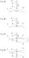
- Figs. 5A to 5D are diagrams showing one example of a procedure of setting the initial incised position P1 and the motion center position P2.
- the operator O manipulates the manipulating apparatus 2 to make the instrument 42 approach the cannula 110 attached to the incised part Q1 of the patient Q.
- the operator O manipulates the initial incised position setting manipulation portion 53 to set the position of the tip end of the instrument 42 as the initial incised position P1.
- the cannula 110 is omitted.
- the instrument 42 is further moved in an axial direction (extending direction) of the shaft 43.
- the operator O determines that the tip end of the instrument 42 is located at a desired motion center position
- the operator O manipulates the motion center position setting manipulation portion 54 to set the position of the tip end of the instrument 42 as the motion center position P2.
- the instrument 42 is further moved in the axial direction of the shaft 43 such that the tip end of the instrument 42 is inserted to a desired initial position.
- the shaft 43 is arranged so as to pass through the initial incised position P1 and the motion center position P2.
- the tip ends of the other instruments 42 and the tip end of the endoscope 41 are inserted through the corresponding cannulas 110 into the body to the corresponding desired initial positions. Then, the medical treatment is practically started.
- the position of the tip end of the instrument 42 at the time of this manipulation is set as the initial incised position P1.
- the position of the tip end of the instrument 42 at the time of this manipulation is set as the motion center position P2.
- the motion center position P2 may be automatically set by being calculated as a position away from the initial incised position P1 by a predetermined distance (A) in the axial direction of the instrument 42 (i.e., the axial direction of the shaft 43).
- positions P1 and P2 are stored in, for example, the slave-side control portion 62 of the control apparatus 6 by using three-dimensional position coordinates.
- the three-dimensional position coordinates of the positions P1 and P2 can be calculated from: three-dimensional position coordinates of a reference position Ps1 (see Fig. 3 ) of the base end of the arm 3 to which the instrument 42 is attached; rotational positions (output values of the encoders) of the joints of the arm 3; lengths of the links constituting the arm 3; a length from the holder 36 to the tip end of the instrument 42; and the like.
- the three-dimensional position coordinates of the reference position Ps1 of the base end of the arm 3 may be calculated by using a three-dimensional orthogonal coordinate having an origin that is a predetermined position of the base 70 of the positioner 7. Further, in this example, after the platform 5 is first positioned, the platform 5 is in a fixed state. Therefore, as to each arm 3, the three-dimensional position coordinates of the reference position (Ps1, for example) of the base end of the arm 3 may be regarded as the origin.
- the operator O manipulates the manipulating apparatus 2 to change the position and posture of the instrument 42.
- the slave-side control portion 62 of the control apparatus 6 controls the operation of the arm 3 such that the position and posture of the instrument 42 are changed while maintaining a state where the shaft 43 of the instrument 42 is located at the motion center position P2. With this, the position and posture of the tip end of the instrument 42 are changed while maintaining a state where the shaft 43 passes through the motion center position P2.
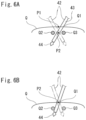
- the motion center position P2 of the instrument 42 is set in (an inner part of) the body of the patient, instead of on the body surface of the patient or near the body surface of the patient. With this, even when the instrument 42 is inserted into a narrow region, for example, a region between bones, such as ribs, in thoracic surgery or the like, a large movable range of the tip end of the instrument 42 can be secured.
- Fig. 6A is a diagram showing an operating state of the instrument 42 in one example of the present embodiment.
- Fig. 6B is a diagram showing an operating state of the instrument 42 in Comparative Example. It should be noted that in Figs. 6A and 6B , the cannula 110 (see Fig. 5A ) attached to the incised part Q1 is omitted.
- the motion center position P2 of the instrument 42 is set between bones Q2 and Q3 in the inner part of the body of the patient Q.
- the motion center position P2 of the instrument 42 is set at a position of the incised part Q1 on the body surface of the patient Q.
- the manipulating apparatus 2 includes the warning device 56 (see Fig. 4 ) configured to output a warning to the operator O when the incised part Q1 is largely displaced from the initial incised position P1.
- the slave-side control portion 62 of the control apparatus 6 includes a warning determining portion 63 configured to determine based on a predetermined warning determination condition whether to output the warning from the warning device 56.
- the warning determining portion 63 determines that the warning is output, the warning determining portion 63 outputs a warning signal to the warning device 56.
- the warning device 56 outputs the warning.
- the warning device 56 warns the operator O by at least one of sound, light, and an image.
- the warning device 56 may be a buzzer, a unit configured to generate voice by electronic sound, or a light emitting unit, such as a lamp.
- the display device 55 may be used as the warning device 56, and a warning image (such as letters, signals, etc. indicating the waning) may be displayed on the screen image of the display device 55.
- Figs. 7A, 7B, and 7C are diagrams for explaining the warning determination condition in the warning determining portion 63. It should be noted that in Figs. 7A to 7C , the cannula 110 (see Fig. 5A ) attached to the incised part Q1 is omitted. Further, as described above, the three-dimensional position coordinates of the initial incised position P1 and the motion center position P2 are stored in the slave-side control portion 62.
- the warning determining portion 63 sets a distance between the initial incised position P1 and the motion center position P2 (also see Fig. 5C ) as a distance A and calculates a position P10 located on a central axis of the current shaft 43 and away from the motion center position P2 toward the base end of the shaft 43 by the distance A. Then, the warning determining portion 63 calculates a distance B1 between the position P10 and the initial incised position P1 at all times. When the distance B1 is not less than a predetermined value, the warning determining portion 63 determines that the warning is output. Then, the warning determining portion 63 outputs the warning signal.
- the warning determining portion 63 obtains a flat plane C perpendicular to a vector (vector parallel to a straight line L5) passing through the initial incised position P1 and extending from the motion center position P2 toward the initial incised position P1. Then, the warning determining portion 63 calculates a distance B2 between a position P11 where the flat plane C and a central axis L6 of the current shaft 43 intersect with each other and the initial incised position P1 at all times. When the distance B2 is not less than a predetermined value, the warning determining portion 63 determines that the warning is output. Then, the warning determining portion 63 outputs the warning signal.
- the flat plane C be a flat plane passing through the initial incised position P1 substantially along the body surface of the patient Q.
- the flat plane C may be a horizontal surface passing through the initial incised position P1.
- each of the calculation of the distance B1 in Fig. 7A and the calculation of the distance B2 in Fig. 7B is a calculation of an approximate value or rough value of a distance between the center position of the current incised part Q1 (i.e., the incised part Q1 at the time of the calculation) and the initial incised position P1.
- the warning determination condition in each of Figs. 7A and 7B is a condition in which the approximate value or rough value (distance B1, B2) of the distance between the center position of the current incised part Q1 and the initial incised position P1 is not less than the predetermined value.
- the warning determining portion 63 calculates at all times an angle ⁇ formed by a direction of the central axis (straight line L5) of the shaft 43 when the motion center position P2 is set and a direction of the central axis L6 of the current shaft 43.
- the warning determining portion 63 determines that the warning is output. Then, the warning determining portion 63 outputs the warning signal.
- the warning determination condition in this case is a condition in which the angle ⁇ is not less than the predetermined angle.
- the angle ⁇ can be calculated by using: information (first vector) of the direction of the central axis (straight line L5) of the shaft 43 when the motion center position P2 is set; information (second vector) of the direction of the central axis L6 of the current shaft 43; and an inner product of these vectors. Since the central axis of the shaft 43 passes through the motion center position P2 at all times, the vector (first or second vector) indicating the direction of the central axis of the shaft 43 at an arbitrary point of time can be calculated from: the motion center position P2; and a reference position Ps2 (see Fig. 3 ) of the base end of the shaft 43 at the arbitrary point of time.
- the reference position Ps2 of the base end of the shaft 43 can be calculated from: the three-dimensional position coordinates of the reference position Ps1 of the base end of the arm 3; the rotational positions (output values of the encoders) of the joints of the arm 3; lengths of the links constituting the arm 3; and the like.
- warning determining portion 63 is only required to perform the determination based on the warning determination condition explained in any one of Figs. 7A, 7B, and 7C .
- the operator O manipulates the manipulating apparatus 2 to move the arm 3. Then, when the position of the tip end of the instrument 42 is located at the initial incised position P1, the operator O manipulates the setting manipulation portion 53 to set the position P1, and when the position of the tip end of the instrument 42 is located at the desired motion center position P2, the operator O manipulates the setting manipulation portion 54 to set the position P2.
- a camera may be additionally provided to take an image of the body surface, to which the cannula 110 is attached, of the patient Q. The image taken by the camera may be displayed on the screen image of the display device 55, and the operator O may perform manipulation while watching the screen image.
- the position P1 may be set when the position of the tip end of the instrument 42 is located at the initial incised position P1 after the arm 3 is directly moved by a hand of an assistant operator
- the position P2 may be set when the position of the tip end of the instrument 42 is located at the desired motion center position P2 after the arm 3 is directly moved by a hand of an assistant operator.
- the position P1 and the position P2 may be set by manipulating a remote controller having the function of the initial incised position setting manipulation portion 53 and the function of the motion center position setting manipulation portion 54.
- the position of the tip end of the instrument 42 is set as the reference point, and the initial incised position P1 and the motion center position P2 are set by the position of the tip end of the instrument 42.
- a reference point may be provided in the vicinity of the tip end of the shaft 43 of the instrument 42, a mark (a colored mark, an engraved mark, or the like) of the reference point may be put on the shaft 43, and the initial incised position P1 and the motion center position P2 may be set by the position of the reference point.
- a special arm 3 having a tip end to which a probe for setting the initial incised position is attached may be used, and the initial incised position P1 may be set by the position of the tip end of the probe.
- a three-dimensional position sensor may be attached to the patient-side apparatus 1 and detect the position of the incised part Q1, and then, the detected position may be input to the control apparatus 6 and set as the initial incised position P1.
- coordinates of the position detected by the three-dimensional position sensor need to be converted into coordinates of the patient-side apparatus 1 and then set as the initial incised position P1.
- the motion center position P2 may be set as, for example, a position located away from the initial incised position P1 by a predetermined distance in a predetermined direction (for example, a vertically downward direction).
- the manipulating apparatus 2 may include a mode selecting portion configured to select a first operating mode used when thoracic surgery or the like is performed and a second operating mode used when abdominal surgery or the like is performed.
- the motion center position P2 is set in the body, i.e., in the inner part under the body surface of the patient Q as described above.
- the initial incised position P1 is set at the position of the incised part Q1 on the body surface of the patient Q.
- the motion center position P2 is set at the position of the incised part Q1 on the body surface of the patient Q, and the function of setting the initial incised position P1 may be stopped. Further, when the second operating mode is selected, the function of the warning determining portion 63 is also stopped.
- the present invention is useful as, for example, a surgical system capable of securing a large movable range of a tip end of a surgical instrument even when the surgical instrument is inserted into a narrow region, for example, a region between bones, such as ribs.
- the present invention also relates to aspects, embodiments and features described in the following itemized list:
Landscapes
- Health & Medical Sciences (AREA)
- Engineering & Computer Science (AREA)
- Life Sciences & Earth Sciences (AREA)
- Surgery (AREA)
- Robotics (AREA)
- Medical Informatics (AREA)
- Biomedical Technology (AREA)
- Heart & Thoracic Surgery (AREA)
- Nuclear Medicine, Radiotherapy & Molecular Imaging (AREA)
- Molecular Biology (AREA)
- Animal Behavior & Ethology (AREA)
- General Health & Medical Sciences (AREA)
- Public Health (AREA)
- Veterinary Medicine (AREA)
- Oral & Maxillofacial Surgery (AREA)
- Pathology (AREA)
- Mechanical Engineering (AREA)
- Manipulator (AREA)
Applications Claiming Priority (3)
| Application Number | Priority Date | Filing Date | Title |
|---|---|---|---|
| JP2016081856A JP6831642B2 (ja) | 2016-04-15 | 2016-04-15 | 外科手術システム |
| EP17782442.2A EP3443928B1 (de) | 2016-04-15 | 2017-04-12 | Chirurgisches system |
| PCT/JP2017/015020 WO2017179629A1 (ja) | 2016-04-15 | 2017-04-12 | 外科手術システム |
Related Parent Applications (1)
| Application Number | Title | Priority Date | Filing Date |
|---|---|---|---|
| EP17782442.2A Division EP3443928B1 (de) | 2016-04-15 | 2017-04-12 | Chirurgisches system |
Publications (2)
| Publication Number | Publication Date |
|---|---|
| EP4309853A2 true EP4309853A2 (de) | 2024-01-24 |
| EP4309853A3 EP4309853A3 (de) | 2024-03-27 |
Family
ID=60042165
Family Applications (2)
| Application Number | Title | Priority Date | Filing Date |
|---|---|---|---|
| EP23213956.8A Pending EP4309853A3 (de) | 2016-04-15 | 2017-04-12 | Chirurgisches system |
| EP17782442.2A Active EP3443928B1 (de) | 2016-04-15 | 2017-04-12 | Chirurgisches system |
Family Applications After (1)
| Application Number | Title | Priority Date | Filing Date |
|---|---|---|---|
| EP17782442.2A Active EP3443928B1 (de) | 2016-04-15 | 2017-04-12 | Chirurgisches system |
Country Status (7)
| Country | Link |
|---|---|
| US (1) | US11033347B2 (de) |
| EP (2) | EP4309853A3 (de) |
| JP (1) | JP6831642B2 (de) |
| CN (1) | CN108882969B (de) |
| DE (1) | DE202017007688U1 (de) |
| ES (1) | ES2965135T3 (de) |
| WO (1) | WO2017179629A1 (de) |
Families Citing this family (10)
| Publication number | Priority date | Publication date | Assignee | Title |
|---|---|---|---|---|
| KR102735980B1 (ko) * | 2016-06-09 | 2024-12-02 | 인튜어티브 서지컬 오퍼레이션즈 인코포레이티드 | 컴퓨터 보조 원격 조작 수술 시스템 및 방법 |
| JP6685052B2 (ja) * | 2018-08-30 | 2020-04-22 | リバーフィールド株式会社 | 推定装置、推定方法およびプログラム |
| JP6469304B1 (ja) * | 2018-10-23 | 2019-02-13 | 株式会社A−Traction | 手術支援装置、その制御方法及びプログラム |
| JP2020162642A (ja) | 2019-03-28 | 2020-10-08 | 川崎重工業株式会社 | クリップアプライヤーシステム |
| JP7257283B2 (ja) * | 2019-08-08 | 2023-04-13 | 川崎重工業株式会社 | 手術マニピュレータの入力装置 |
| JP7260666B2 (ja) * | 2019-12-05 | 2023-04-18 | 川崎重工業株式会社 | 手術システム、手術支援ロボット及びその制御方法 |
| JP7171647B2 (ja) * | 2020-04-28 | 2022-11-15 | 川崎重工業株式会社 | 手術支援ロボット、ピボット位置設定方法および外科手術システム |
| JP2023018313A (ja) | 2021-07-27 | 2023-02-08 | 川崎重工業株式会社 | 手術支援システムおよびピボット位置設定方法 |
| CN113524257A (zh) * | 2021-09-10 | 2021-10-22 | 深圳市资福医疗技术有限公司 | 一种重力平衡支撑臂及应用其的磁锚定设备 |
| CN116158863A (zh) * | 2023-02-17 | 2023-05-26 | 深圳微美机器人有限公司 | 控制方法、操作台系统及医疗设备 |
Citations (1)
| Publication number | Priority date | Publication date | Assignee | Title |
|---|---|---|---|---|
| JP2002530209A (ja) | 1998-11-23 | 2002-09-17 | マイクロデクステラティー・システムズ・インコーポレーテッド | 外科用マニプレータ |
Family Cites Families (31)
| Publication number | Priority date | Publication date | Assignee | Title |
|---|---|---|---|---|
| US6436107B1 (en) * | 1996-02-20 | 2002-08-20 | Computer Motion, Inc. | Method and apparatus for performing minimally invasive surgical procedures |
| US6364888B1 (en) * | 1996-09-09 | 2002-04-02 | Intuitive Surgical, Inc. | Alignment of master and slave in a minimally invasive surgical apparatus |
| US6594552B1 (en) * | 1999-04-07 | 2003-07-15 | Intuitive Surgical, Inc. | Grip strength with tactile feedback for robotic surgery |
| US8004229B2 (en) * | 2005-05-19 | 2011-08-23 | Intuitive Surgical Operations, Inc. | Software center and highly configurable robotic systems for surgery and other uses |
| US7594912B2 (en) * | 2004-09-30 | 2009-09-29 | Intuitive Surgical, Inc. | Offset remote center manipulator for robotic surgery |
| US7607440B2 (en) * | 2001-06-07 | 2009-10-27 | Intuitive Surgical, Inc. | Methods and apparatus for surgical planning |
| US8010180B2 (en) | 2002-03-06 | 2011-08-30 | Mako Surgical Corp. | Haptic guidance system and method |
| JP4528136B2 (ja) * | 2005-01-11 | 2010-08-18 | 株式会社日立製作所 | 手術装置 |
| CN101160104B (zh) | 2005-02-22 | 2012-07-04 | 马科外科公司 | 触觉引导系统及方法 |
| US9789608B2 (en) * | 2006-06-29 | 2017-10-17 | Intuitive Surgical Operations, Inc. | Synthetic representation of a surgical robot |
| US8062211B2 (en) * | 2006-06-13 | 2011-11-22 | Intuitive Surgical Operations, Inc. | Retrograde instrument |
| EP1915963A1 (de) | 2006-10-25 | 2008-04-30 | The European Atomic Energy Community (EURATOM), represented by the European Commission | Kraftabschätzung für ein minimal-invasives Roboterchirurgiesystem |
| JP2008188115A (ja) * | 2007-02-01 | 2008-08-21 | Olympus Corp | スタビライザ |
| JP5033650B2 (ja) * | 2008-01-10 | 2012-09-26 | 三鷹光器株式会社 | オフセット型手術用マニピュレータ及び手術用顕微鏡システム |
| US8423186B2 (en) * | 2009-06-30 | 2013-04-16 | Intuitive Surgical Operations, Inc. | Ratcheting for master alignment of a teleoperated minimally-invasive surgical instrument |
| US9119655B2 (en) * | 2012-08-03 | 2015-09-01 | Stryker Corporation | Surgical manipulator capable of controlling a surgical instrument in multiple modes |
| JP5796982B2 (ja) * | 2011-03-31 | 2015-10-21 | オリンパス株式会社 | 手術用システムの制御装置及び制御方法 |
| CN102499759B (zh) * | 2011-10-31 | 2013-11-20 | 上海交通大学 | 多自由度单创孔腹腔微创手术机器人灵巧手 |
| US10687911B2 (en) | 2011-12-05 | 2020-06-23 | Koninklijke Philips N.V. | Positioning and orientation of surgical tools during patient specific port placement |
| CN104349741B (zh) * | 2012-06-01 | 2017-03-22 | 直观外科手术操作公司 | 手术器械操纵器方面 |
| JP6310455B2 (ja) * | 2012-08-02 | 2018-04-11 | コーニンクレッカ フィリップス エヌ ヴェKoninklijke Philips N.V. | ロボット遠隔運動中心のコントローラ定義 |
| CN104736093B (zh) * | 2012-08-15 | 2018-06-05 | 直观外科手术操作公司 | 接头估测和控制中的假想自由度 |
| JP6250673B2 (ja) * | 2012-08-15 | 2017-12-20 | インテュイティブ サージカル オペレーションズ, インコーポレイテッド | 手動でのロボットアームの運動によって制御される可動な手術用装着プラットフォーム |
| BR112015020589B8 (pt) * | 2013-02-26 | 2022-03-22 | Sinan Kabakci Ahmet | Sistema manipulador robótico |
| KR102422496B1 (ko) * | 2013-03-15 | 2022-07-20 | 인튜어티브 서지컬 오퍼레이션즈 인코포레이티드 | 로봇 수술 시스템에서의 수술 중 도구의 교환 |
| CA2905968A1 (en) * | 2013-03-15 | 2014-09-25 | Sri International | Hyperdexterous surgical system |
| WO2014199413A1 (ja) * | 2013-06-13 | 2014-12-18 | テルモ株式会社 | 医療用マニピュレータおよびその制御方法 |
| US10076348B2 (en) * | 2013-08-15 | 2018-09-18 | Intuitive Surgical Operations, Inc. | Rotary input for lever actuation |
| JP6218631B2 (ja) | 2014-02-18 | 2017-10-25 | オリンパス株式会社 | マニピュレータ装置の作動方法 |
| US20160081753A1 (en) * | 2014-09-18 | 2016-03-24 | KB Medical SA | Robot-Mounted User Interface For Interacting With Operation Room Equipment |
| EP3628264B1 (de) * | 2015-03-17 | 2024-10-16 | Intuitive Surgical Operations, Inc. | Systeme und verfahren zur darstellung einer bildschirmidentifizierung von instrumenten in einem teleoperativen medizinischen system |
-
2016
- 2016-04-15 JP JP2016081856A patent/JP6831642B2/ja active Active
-
2017
- 2017-04-12 DE DE202017007688.8U patent/DE202017007688U1/de active Active
- 2017-04-12 ES ES17782442T patent/ES2965135T3/es active Active
- 2017-04-12 EP EP23213956.8A patent/EP4309853A3/de active Pending
- 2017-04-12 WO PCT/JP2017/015020 patent/WO2017179629A1/ja not_active Ceased
- 2017-04-12 US US16/093,699 patent/US11033347B2/en active Active
- 2017-04-12 EP EP17782442.2A patent/EP3443928B1/de active Active
- 2017-04-12 CN CN201780022845.2A patent/CN108882969B/zh active Active
Patent Citations (1)
| Publication number | Priority date | Publication date | Assignee | Title |
|---|---|---|---|---|
| JP2002530209A (ja) | 1998-11-23 | 2002-09-17 | マイクロデクステラティー・システムズ・インコーポレーテッド | 外科用マニプレータ |
Also Published As
| Publication number | Publication date |
|---|---|
| EP3443928C0 (de) | 2023-12-06 |
| WO2017179629A1 (ja) | 2017-10-19 |
| JP6831642B2 (ja) | 2021-02-17 |
| ES2965135T3 (es) | 2024-04-11 |
| CN108882969B (zh) | 2021-07-06 |
| JP2017189495A (ja) | 2017-10-19 |
| US20190133704A1 (en) | 2019-05-09 |
| DE202017007688U1 (de) | 2024-05-27 |
| US11033347B2 (en) | 2021-06-15 |
| CN108882969A (zh) | 2018-11-23 |
| EP4309853A3 (de) | 2024-03-27 |
| EP3443928B1 (de) | 2023-12-06 |
| EP3443928A4 (de) | 2019-12-11 |
| EP3443928A1 (de) | 2019-02-20 |
Similar Documents
| Publication | Publication Date | Title |
|---|---|---|
| EP3443928B1 (de) | Chirurgisches system | |
| CN115363770B (zh) | 用于控制外科器械的系统和方法 | |
| JP2021511087A (ja) | 制御可能な操縦可能器具 | |
| JP7755379B2 (ja) | 手術支援ロボットシステムおよび手術支援ロボットの制御方法 | |
| US12324639B2 (en) | Surgical system and method of controlling surgical manipulator arm | |
| US10932856B2 (en) | Surgical system control method and surgical system | |
| US12029518B2 (en) | Method of controlling surgical system and surgical system | |
| JP7521172B2 (ja) | 手術システム | |
| US20250041008A1 (en) | Surgical robot, surgical system, and control method | |
| US12171513B2 (en) | Surgical system and patient-side apparatus | |
| US20220175479A1 (en) | Surgical operation system and method of controlling surgical operation system | |
| US12318164B2 (en) | Systems and methods for controlling a robotic manipulator or associated tool | |
| JPH08215205A (ja) | 医療用マニピュレータ | |
| US11717366B2 (en) | Medical manipulator | |
| JP7105272B2 (ja) | 手術支援ロボットおよび手術支援ロボットシステム | |
| JP2006312079A (ja) | 医療用マニピュレータ | |
| US11648067B2 (en) | Medical manipulator and surgical system including the same | |
| JP2026074346A (ja) | 手術支援システム、ピボット位置設定方法およびプログラム |
Legal Events
| Date | Code | Title | Description |
|---|---|---|---|
| PUAI | Public reference made under article 153(3) epc to a published international application that has entered the european phase |
Free format text: ORIGINAL CODE: 0009012 |
|
| STAA | Information on the status of an ep patent application or granted ep patent |
Free format text: STATUS: THE APPLICATION HAS BEEN PUBLISHED |
|
| AC | Divisional application: reference to earlier application |
Ref document number: 3443928 Country of ref document: EP Kind code of ref document: P |
|
| AK | Designated contracting states |
Kind code of ref document: A2 Designated state(s): AL AT BE BG CH CY CZ DE DK EE ES FI FR GB GR HR HU IE IS IT LI LT LU LV MC MK MT NL NO PL PT RO RS SE SI SK SM TR |
|
| PUAL | Search report despatched |
Free format text: ORIGINAL CODE: 0009013 |
|
| AK | Designated contracting states |
Kind code of ref document: A3 Designated state(s): AL AT BE BG CH CY CZ DE DK EE ES FI FR GB GR HR HU IE IS IT LI LT LU LV MC MK MT NL NO PL PT RO RS SE SI SK SM TR |
|
| RIC1 | Information provided on ipc code assigned before grant |
Ipc: A61B 34/37 20160101ALI20240216BHEP Ipc: A61B 34/35 20160101ALI20240216BHEP Ipc: B25J 3/00 20060101AFI20240216BHEP |
|
| STAA | Information on the status of an ep patent application or granted ep patent |
Free format text: STATUS: REQUEST FOR EXAMINATION WAS MADE |
|
| 17P | Request for examination filed |
Effective date: 20240926 |
|
| RBV | Designated contracting states (corrected) |
Designated state(s): AL AT BE BG CH CY CZ DE DK EE ES FI FR GB GR HR HU IE IS IT LI LT LU LV MC MK MT NL NO PL PT RO RS SE SI SK SM TR |
|
| GRAP | Despatch of communication of intention to grant a patent |
Free format text: ORIGINAL CODE: EPIDOSNIGR1 |
|
| STAA | Information on the status of an ep patent application or granted ep patent |
Free format text: STATUS: GRANT OF PATENT IS INTENDED |
|
| INTG | Intention to grant announced |
Effective date: 20260212 |