EP4309538B1 - Schuhsohle und schuh - Google Patents
Schuhsohle und schuh Download PDFInfo
- Publication number
- EP4309538B1 EP4309538B1 EP21937845.2A EP21937845A EP4309538B1 EP 4309538 B1 EP4309538 B1 EP 4309538B1 EP 21937845 A EP21937845 A EP 21937845A EP 4309538 B1 EP4309538 B1 EP 4309538B1
- Authority
- EP
- European Patent Office
- Prior art keywords
- shoe sole
- midsole
- foot
- wall portion
- outsole
- Prior art date
- Legal status (The legal status is an assumption and is not a legal conclusion. Google has not performed a legal analysis and makes no representation as to the accuracy of the status listed.)
- Active
Links
Images


Classifications
-
- A—HUMAN NECESSITIES
- A43—FOOTWEAR
- A43B—CHARACTERISTIC FEATURES OF FOOTWEAR; PARTS OF FOOTWEAR
- A43B13/00—Soles; Sole-and-heel integral units
- A43B13/02—Soles; Sole-and-heel integral units characterised by the material
- A43B13/12—Soles with several layers of different materials
- A43B13/122—Soles with several layers of different materials characterised by the outsole or external layer
-
- A—HUMAN NECESSITIES
- A43—FOOTWEAR
- A43B—CHARACTERISTIC FEATURES OF FOOTWEAR; PARTS OF FOOTWEAR
- A43B13/00—Soles; Sole-and-heel integral units
- A43B13/14—Soles; Sole-and-heel integral units characterised by the constructive form
-
- A—HUMAN NECESSITIES
- A43—FOOTWEAR
- A43B—CHARACTERISTIC FEATURES OF FOOTWEAR; PARTS OF FOOTWEAR
- A43B13/00—Soles; Sole-and-heel integral units
- A43B13/14—Soles; Sole-and-heel integral units characterised by the constructive form
- A43B13/141—Soles; Sole-and-heel integral units characterised by the constructive form with a part of the sole being flexible, e.g. permitting articulation or torsion
-
- A—HUMAN NECESSITIES
- A43—FOOTWEAR
- A43B—CHARACTERISTIC FEATURES OF FOOTWEAR; PARTS OF FOOTWEAR
- A43B13/00—Soles; Sole-and-heel integral units
- A43B13/14—Soles; Sole-and-heel integral units characterised by the constructive form
- A43B13/18—Resilient soles
- A43B13/181—Resiliency achieved by the structure of the sole
- A43B13/186—Differential cushioning region, e.g. cushioning located under the ball of the foot
Definitions
- the present invention relates to a shoe sole, and a shoe including the shoe sole.
- an object of the present invention which has been made to solve the above-stated problem, is to provide a shoe sole in which stability when in a standing posture and an impact absorbing performance at the time of a cutting maneuver are made compatible, and a shoe including the shoe sole.
- a shoe sole in which stability when in a standing posture and an impact absorbing performance at the time of a cutting maneuver are made compatible, and a shoe including the shoe sole, can be produced.
- Fig. 1 is a schematic perspective view of a shoe sole and a shoe including the shoe sole relating to Embodiment 1.
- a schematic configuration of a shoe 1, and a shoe sole 100A included in the shoe 1, relating to the present embodiment will be described with reference to Fig. 1 .
- dark coloring is added to an outsole 130, which will be described below, and light coloring is added to portions corresponding to a first protruding portion 111 and a second protruding portion 112 (refer to Fig. 2 to Fig. 9 ) of a midsole 110, which will be described below (note that, this is the same for Fig. 2 to Fig. 5 , Fig. 7 , Fig. 9 to Fig. 11 , and Fig. 14 , which will be described below).
- the shoe 1 includes the shoe sole 100A and an upper 200.
- the shoe sole 100A is a member that covers a sole of a foot of a wearer, and has an approximate flat shape.
- the upper 200 has a bag-type shape that encloses the entire inserted foot of the wearer, and is located above the shoe sole 100A.
- the upper 200 has an upper body 210, a shoe tongue 220, and a shoelace 230.
- the upper body 210 is a member that becomes a base of the upper 200, and has a bag-type shape.
- the shoe tongue 220 and the shoelace 230 are both fixed or attached to the upper body 210.
- a bottom portion fixed to the shoe sole 100A is located on a lower portion of the upper body 210, and an opening portion, where an upper portion of an ankle and a part of the top of the foot are exposed, is provided on an upper portion of the upper body 210.
- the shoe tongue 220 is fixed, by sewing, welding, bonding, or a combination thereof, to the upper body 210 so as to cover a portion of the opening portion provided in the upper body 210 where the top part of the foot is exposed.
- Woven or knitted fabric, synthetic leather, resin or the like is used, for example, as the upper body 210 and the shoe tongue 220, and a double raschel warp knitted fabric with a polyester yarn knitted therein is used for a shoe that is required, in particular, to be air permeable and lightweight.
- the shoelace 230 is a string-type member for pulling together peripheral edges of the opening portion, where a part of the top of the foot is exposed, provided in the upper body 210, in a foot width direction, and is passed through a plurality of hole portions provided on the peripheral edges of the opening portion.
- the shoelace 230 is tightened in a state where the foot of the wearer is inserted into the upper body 210, and the upper body 210 and the shoe tongue 220 can be brought into close contact with the foot.
- the shoe sole 100A has a midsole 110, a reinforcing structure portion 120, and an outsole 130.
- the midsole 110, the reinforcing structure portion 120, and the outsole 130 are integrated with each other, thereby the shoe sole 100A has an overall approximate flat shape, such as stated above.
- the outsole 130 has a ground contact surface 134 (refer to Fig. 2 to Fig. 7 ) on the lower surface thereof, and the midsole 110 is located above the outsole 130. Moreover, the reinforcing structure portion 120 has a part thereof embedded in the midsole 110, and another part located to be exposed from the midsole 110.
- Fig. 2 is a perspective view of the shoe sole shown in Fig. 1
- Fig. 3 and Fig. 4 are a side surface view on a medial foot side and a side surface view on a lateral foot side, respectively, of the shoe sole shown in Fig. 1
- Fig. 5 is a bottom surface view of the shoe sole shown in Fig. 1
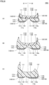
- Fig. 6(A) to Fig. 6(C) are cross-section views along a VIA-VIA line to a VIC-VIC line, respectively, shown in Fig. 5
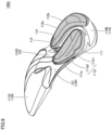
- Fig. 7 is an exploded perspective view of the shoe sole shown in Fig. 1
- Fig. 7 is an exploded perspective view of the shoe sole shown in Fig. 1
- Fig. 7 is an exploded perspective view of the shoe sole shown in Fig. 1
- Fig. 7 is an exploded perspective view of the shoe sole shown in Fig. 1
- Fig. 7 is an exploded perspective view of the shoe sole shown in Fig. 1
- FIG. 8 is a bottom surface view showing a state where an outsole and a rear side midsole are removed from the shoe sole shown in Fig. 1 .
- Fig. 9 is a perspective view showing a state where an outsole is removed from the shoe sole shown in Fig. 1 .
- the shoe sole 100A is divided into a forefoot portion R1 for supporting a toe portion and a ball portion of the foot of the wearer, a midfoot portion R2 for supporting an arch portion of the foot of the wearer, and a rearfoot portion R3 for supporting a heel portion of the foot of the wearer, along a front-rear direction (left-right direction in the figures in Fig. 3 and Fig. 4 , up-down direction in the figure in Fig. 5 ) that is a direction coinciding with a foot length direction of the foot of the wearer in a plan view state.
- a front-rear direction left-right direction in the figures in Fig. 3 and Fig. 4 , up-down direction in the figure in Fig. 5
- the shoe sole 100A is divided into a portion on a medial foot side (portion on the S1 side shown in the figure) that is a medial side of the foot in an anatomical position (namely, a side close to a midline), and a portion on a lateral foot side (portion on the S2 side shown in the figure) that is on an opposite side to the medial side of the foot in an anatomical position (namely, a side away from the midline), along a left-right direction (left-right direction in the figure) that is a direction coinciding with a foot width direction of the foot of the wearer in a plan view state.
- the rear end portion of the front side midsole 110A and the front end portion of the rear side midsole 110B are overlapping in an up-down direction (namely, a direction orthogonal to both the above-stated front-rear direction and left-right direction) (in particular, refer to Fig. 6(A), Fig. 6(B) , and Fig. 7 ).
- the front side midsole 110A and the rear side midsole 110B are overlapping, so that the front side midsole 110A is located on the upper 200 side and the rear side midsole 110B is located on the outsole 130 side.
- the midsole 110 is formed by the front side midsole 110A, in the portion near the rear end of the midfoot portion R2 and the portion near the front end of the rearfoot portion R3, the midsole 110 is formed by the overlapping portions of the front side midsole 110A and the rear side midsole 110B, and in the portion near the rear end of the rearfoot portion R3, the midsole 110 is formed by the rear side midsole 110B.
- the upper surface of the midsole 110 prescribes an upper surface of the shoe sole 100A, and the peripheral edge thereof has a protruding shape compared to the surroundings (in particular, refer to Fig. 3 , Fig. 4 , and Fig. 6 ).
- a concave-shaped portion is provided on the upper surface of the midsole 110, and this concave-shaped portion becomes a portion in which the upper 200 is received.
- the portion on the upper surface of the midsole 110, other than the peripheral edge that is a bottom surface of this concave-shaped portion, has a smooth curved surface shape so as to fit the sole of the wearer.
- the outsole 130 apart from a part of the midfoot portion R2, is located continuously from roughly the forefoot portion R1 to the rearfoot portion R3.
- the outsole 130 includes a rear medial foot side outsole 131 as a first cover portion, a rear lateral foot side outsole 132 as a second cover portion, and a front side outsole 133 as a third cover portion.
- the front side outsole 133 is located straddling across the forefoot portion R1 and the portion near the front end of the midfoot portion R2, and the rear medial foot side outsole 131 and the rear lateral foot side outsole 132 are each located straddling across the portion near the rear end of the midfoot portion R2 and the rearfoot portion R3.
- the rear medial foot side outsole 131 is located at a portion on the medial foot side from among the portion near the rear end of the midfoot portion R2 and the rearfoot portion R3, and the rear lateral foot side outsole 132 is located at a portion on the lateral foot side from among the portion near the rear end of the midfoot portion R2 and the rearfoot portion R3.
- each of the rear medial foot side outsole 131, the rear lateral foot side outsole 132, and the front side outsole 133 forms the ground contact surface 134 such as stated above, in order to improve the grip performance, a tread pattern may be formed by having protrusions and recesses formed on an exposed surface thereof.
- Each of the rear medial foot side outsole 131, the rear lateral foot side outsole 132, and the front side outsole 133 has an upper surface thereof joined to the lower surface of the midsole 110.
- the midsole 110 (namely, the front side midsole 110A and the rear side midsole 110B) is excellent in a shock absorbing performance while having a suitable strength, and from this viewpoint, for example, a foam material made of resin, which includes a resin material as a main component and a foaming agent and a crosslinking agent as secondary components, is used as the midsole 110.
- a foam material made of rubber which includes a rubber material as a main component and a plasticizer, a foaming agent, a reinforcing agent, and a crosslinking agent as secondary agents, may be used.
- EVA ethylene-vinyl acetate copolymer
- a polyolefin resin a thermoplastic polyurethane
- a thermoplastic polyamide elastomer TPA, TPAE
- a thermoplastic polyester elastomer e.g., polyester elastomer
- Butadiene rubber can be suitably used, for example, as the rubber material.
- the midsole 110 is generally formed by a member with a lower Young's modulus and more flexible than the outsole 130. Accordingly, the midsole 110 elastically deforms relatively easily in the case where receiving a compressive load. Therefore, the midsole 110 is excellent in a shock absorbing performance. Note that, various types of shock absorbing parts may be included, and reinforcing parts other than the reinforcing structure portion 120, which will be described below, may be included, at prescribed portions of the midsole 110.
- the outsole 130 is generally formed by a member with a higher Young's modulus and harder than the midsole 110. Accordingly, while the outsole 130 does not deform easily compared to the midsole 110 in the case where receiving a compressive load, it is excellent in durability such as wear resistance. Note that, the shape of the outsole 130 and the above-stated tread pattern can be appropriately designed in accordance with a usage of the shoe 1.
- the reinforcing structure portion 120 is disposed so that a large portion thereof is located on the midfoot portion R2, while one part thereof reaches the forefoot portion R1 and the rearfoot portion R3.
- the reinforcing structure portion 120 includes a medial foot side reinforcing member 121 disposed on the medial foot side and a lateral foot side reinforcing member 122 disposed on the lateral foot side.
- the medial foot side reinforcing member 121 and the lateral foot side reinforcing member 122 are both connected to the lower surface and the side surface of the front side midsole 110A and the upper surface of the rear side midsole 110B. More specifically, concave portions with a shape corresponding to the medial foot side reinforcing member 121 and the lateral foot side reinforcing member 122 are provided on the lower surface and the side surface of the front side midsole 110A, and the medial foot side reinforcing member 121 and the lateral foot side reinforcing member 122 are connected to the front side midsole 110A and the rear side midsole 110B in a state where housed in these concave portions.
- the medial foot side reinforcing member 121 includes a medial foot side bar portion 121a extending in an oblique direction so as to reach a portion near the rear end of the midfoot portion R2 on the medial foot side from a portion near the front end of the forefoot portion R1 on the lateral foot side
- the lateral foot side reinforcing member 122 includes a lateral foot side bar portion 122a extending in an oblique direction so as to reach a portion near the rear end of the midfoot portion R2 on the medial foot side from a portion near the rear end of the forefoot portion R1 on the lateral foot side.
- each of the front side midsole 110A, the rear side midsole 110B, the medial foot side reinforcing member 121, the lateral foot side reinforcing member 122, the rear medial foot side outsole 131, the rear lateral foot side outsole 132, and the front side outsole 133 may be performed by any type of method, they can be performed, for example, by adhesion or the like.
- a groove portion 113 which extends along the front-rear direction of the shoe sole 100A, is located on the lower surface of the midsole 110 (more strictly, the lower surface of the rear side midsole 110B) at a portion located between the first protruding portion 111 and the second protruding portion 112.
- the first protruding portion 111 includes a first bottom surface 111a located on the ground contact surface 134 side, and a first side surface 111b located on the medial foot side when seen from the first bottom surface 111a.
- the first bottom surface 111a and the first side surface 111b are smoothly connected. Note that, the other side surface of the first protruding portion 111, which is located on the lateral foot side when seen from the first bottom surface 111a, prescribes the above-stated groove portion 113.
- the rear medial foot side outsole 131 as a first cover portion is assembled with the first protruding portion 111.
- the rear medial foot side outsole 131 includes a first bottom wall portion 131a covering the first bottom surface 111a of the first protruding portion 111, and a first side wall portion 131b covering the first side surface 111b of the first protruding portion 111.
- the first bottom wall portion 131a prescribes the above-stated ground contact surface 134 by covering the first bottom surface 111a
- the first side wall portion 131b covers the first side surface 111b by being erected facing upward from a peripheral edge of the first bottom wall portion 131a on the medial foot side.
- the second protruding portion 112 includes a second bottom surface 112a located on the ground contact surface 134 side, and a second side surface 112b located on the lateral foot side when seen from the second bottom surface 112a.
- the second bottom surface 112a and the second side surface 112b are smoothly connected.
- the other side surface of the second protruding portion 112 which is located on the medial foot side when seen from the second bottom surface 112a, prescribes the above-stated groove portion 113.
- the rear lateral foot side outsole 132 as a second cover portion is assembled with the second protruding portion 112.
- the rear lateral foot side outsole 132 includes a second bottom wall portion 132a covering the second bottom surface 112a of the second protruding portion 112, and a second side wall portion 132b covering the second side surface 112b of the second protruding portion 112.
- the second bottom wall portion 132a prescribes the above-stated ground contact surface 134 by covering the second bottom surface 112a
- the second side wall portion 132b covers the second side surface 112b by being erected facing upward from a peripheral edge of the second bottom wall portion 132a on the lateral foot side.
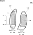
- the ground contact surface 134 prescribed by the first bottom wall portion 131a and the second bottom wall portion 132a is a portion in contact with the ground surface when in a standing posture, which is a state where the wearer is standing on a flat ground surface, and specifically, the portion shown with hatched lines in Fig. 10 and Fig. 12 , which will be described below, corresponds to this surface.
- the portion with hatched lines corresponds to this surface (namely, only the portion in contact with a flat ground surface when in a standing posture corresponds to this surface), and the portion without hatched lines (namely, the portion not in contact with a flat ground surface when in a standing posture) is not included in this surface.
- the front side outsole 133 as a third cover portion is connected to the lower surface of the front side midsole 110A.
- the front side outsole 133 is located straddling across the forefoot portion R1 and a portion near the front end of the midfoot portion R2, and includes a third bottom wall portion 133a covering the lower surface of the front side midsole 110A at this portion.
- the front side outsole 133 has a third side wall portion erected from a peripheral edge of the third bottom wall portion 133a, and the third side wall portion covers the side surface of the front side midsole 110A.
- the shoe 1 and the shoe sole 100A included in the shoe 1 relating to the present embodiment focus on the fact that, in the case where the wearer performs a cutting maneuver, a portion in contact with the ground surface in an initial stage when landing thereof is a portion of the shoe sole on the rear medial foot side, and are applied with improvements to increase a shock absorbing performance in this portion.
- the deformability of the portion of the shoe sole 100A on the rear medial foot side increases, by providing the first protruding portion 111 and the second protruding portion 112, which protrude toward the ground contact surface 134 side, such as stated above, in a state where divided into a medial foot side and a lateral foot side at a portion of the midsole 110 on the rear end side (in other words, by providing the groove portion 113, which extends along the front-rear direction of the shoe sole 100A, at a portion of the midsole 110 on the rear end side), and as a result of this, a shock absorbing performance at the time of a cutting maneuver improves.
- the portion of the shoe sole 100A where the first protruding portion 111 is provided contacts the ground prior to the other portions, and the first protruding portion 111 swiftly and significantly deforms without being affected by the other portions of the midsole 110. Therefore, an impact transmitted to the wearer is absorbed by the deformation of the first protruding portion 111, and as a result, a large shock absorbing performance can be obtained.
- a contrivance is applied to the shape of a peripheral edge of the shoe sole 100A on the medial foot side at the portion where the first protruding portion 111 is provided (more specifically, the shape of a portion corresponding to a specific region SR (refer to Fig. 10 to Fig. 12 ), which will be described below, of a peripheral edge). Therefore, an improvement of a shock absorbing performance and stability when in a standing posture are made compatible. Hereinafter, this point will be described in detail.
- the specific region SR is a region across a prescribed width of the shoe sole 100A in the front-rear direction, a location of a front side thereof is specified by a front side specific location SP1, and a location of a rear end thereof is specified by a rear side specific location SP2.
- the specific region SR includes a portion near the rear end of the midfoot portion R2 and a portion near the front end of the rearfoot portion R3.
- the front side specific location SP1 has a front side end of the shoe sole 100A in the front-rear direction that is set as a reference, and is a location corresponding to a dimension of 70% (a distance L70 shown in the figure corresponds to this dimension) of a dimension from the front side end to a rear side end of the shoe sole 100A in the front-rear direction (a distance L100 shown in the figure corresponds to this dimension).
- the rear side specific location SP2 is a location corresponding to a location of the first bottom wall portion 131a on the rear end side of the rear medial foot side outsole 131 as a first cover portion (namely, the above-stated rear end location of the ground contact surface 134 when in a standing posture provided in the rear medial foot side outsole 131).
- the specific region SR located between the front side specific location SP1 and the rear side specific location SP2 is a region that includes the above-stated portion in contact with the ground surface in an initial stage at the time of a cutting maneuver, and more specifically, an end portion of the specific region SR on the medial foot side alone contacts the ground in an initial stage at the time of a cutting maneuver.
- a first ridgeline RL1 of the rear medial foot side outsole 131 located at a boundary between the first bottom wall portion 131a and the first side wall portion 131b is located so as to separate from a first outline OL1 of the rear medial foot side outsole 131 prescribed by the first side wall portion 131b from the front side specific location SP1 toward the rear side specific location SP2, in the case where seen along a normal direction of the ground contact surface 134.
- a distance between the first ridgeline RL1 and the first outline OL1 increases toward the rear side. Namely, the distances D11 to D13 satisfy the condition of D11 ⁇ D12 ⁇ D13.
- the first bottom wall portion 131a and the first side wall portion 131b are formed continuously with each other. Therefore, by satisfying the above-stated condition, a portion of the first side wall portion 131b located between the first ridgeline RL1 and the first outline OL1 has a size that increases toward the rear side. Since the portion of the first side wall portion 131b located between the first ridgeline RL1 and the first outline OL1 is the above-stated portion that contacts the ground prior to the other portions in an initial stage of a cutting maneuver, an area of this portion increases. Therefore, a load added to the shoe sole 100A when contacting the ground is dispersed, and as a result, a shock absorbing performance increases.
- the shoe sole 100A relating to the present embodiment satisfies the following several conditions, in addition to the above condition.
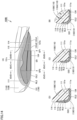
- the first side surface 111b of the first protruding portion 111 of the midsole 110 includes an upper side surface 111b1 substantially orthogonal to the ground contact surface 134, and a lower side surface 111b2 for smoothly connecting the first bottom surface 111a and the upper side surface 111b1, and as shown in Fig. 11(A) , the first side wall portion 131b of the rear medial foot side outsole 131 includes an upper side first side wall portion 131b1 covering the upper side surface 111b1, and a lower side first side wall portion 131b2 covering the lower side surface 111b2.
- a second ridgeline RL2 of the rear medial foot side outsole 131 located at a boundary between the upper side first side wall portion 131b1 and the lower side first side wall portion 131b2 is located so as to separate from a second outline OL2 of the rear medial foot side outsole 131 prescribed by the first bottom wall portion 131a from the front side specific location SP1 toward the rear side specific location SP2, in the case where seen along the left-right direction of the shoe sole 100A.
- a distance between the second ridgeline RL2 and the second outline OL2 increases toward the rear side. Namely, the distances D21 to D23 satisfy the condition of D21 ⁇ D22 ⁇ D23.
- the midsole 110 is divided into the front side midsole 110A and the rear side midsole 110B, the midsole 110 is formed by having these portions overlap each other, and in accordance with this, in the portion where the front side midsole 110A and the rear side midsole 110B overlap, rear end portions 121b and 122b of each of the medial foot side reinforcing member 121 and the lateral foot side reinforcing member 122 are embedded in the midsole 110 by being sandwiched by the front side midsole 110A and the rear side midsole 110B.
- the midsole 110 is located directly on the outsole 130, without interposing the reinforcing structure portion 120. Therefore, a shock absorbing function is maximized.
- the outsole 130 assembled with a portion of the midsole 110 on the rear end side is formed by being divided into the rear medial foot side outsole 131 as a first cover portion and the rear lateral foot side outsole 132 as a second cover portion (namely, as different members in which a first cover portion and a second cover portion are separated from each other), they may be formed of different materials.
- FIG. 14(A) is an enlarged side surface view on the medial foot side of a portion that includes a specific region of a shoe sole relating to Embodiment 2
- Fig. 14(B) to Fig. 14(D) are partial cross-section views along an XIVB-XIVB line to an XIVD-XIVD line, respectively, shown in Fig. 14(A) .
- a shoe sole 100B relating to the present embodiment will be described with reference to Fig. 14 .
- the shoe sole 100B relating to the present embodiment is included in the shoe 1, instead of the shoe sole 100A relating to the above-stated Embodiment 1.
- the shoe sole 100B relating to the present embodiment in the case where compared with the shoe sole 100A relating to the above-stated Embodiment 1, has a configuration that is different only for the point of a concave portion 115 is provided at a prescribed location of the midsole 110.
- the first protruding portion 111 easily deforms with a portion where the concave portion 115 is provided as a base point. Accordingly, by being formed in such a manner, it becomes possible to further increase the deformability of the portion of the shoe sole 100B on the rear medial foot side, and as a result of this, a shock absorbing performance at the time of a cutting maneuver further improves.
- the shape of this portion is not particularly limited to this, and may preferably be a non-concave surface shape such as a convex surface shape or a flat surface shape, or may be a concave surface shape such as a curved concave shape.
- Embodiments 1 and 2 while an explanation has been performed by exemplifying a shoe formed so that the upper body is brought into close contact with the foot by using a shoelace, it may be a shoe formed so that the upper body is brought into close contact with the foot by a hook fastener, or may be a shoe formed so that the upper body is brought into close contact with the foot by forming a sock shaped upper body and thereby only inserting the foot into the upper body.
- the shape of the upper is capable of being appropriately modified in accordance with the usage of the shoe.
Landscapes
- Chemical & Material Sciences (AREA)
- Engineering & Computer Science (AREA)
- Materials Engineering (AREA)
- Footwear And Its Accessory, Manufacturing Method And Apparatuses (AREA)
Claims (13)
- Schuhsohle (100A), in der ein vorderer Fußabschnitt (R1) zum Stützen eines Zehenabschnitts und eines Ballenabschnitts eines Fußes eines Trägers, ein mittlerer Fußabschnitt (R2) zum Stützen eines Gewölbeabschnitts des Fußes des Trägers und ein hinterer Fußabschnitt (R3) zum Stützen eines Fersenabschnitts des Fußes des Trägers bereitgestellt sind, um entlang einer Richtung von vorne nach hinten verbunden zu werden, die eine Richtung ist, die mit einer Fußlängenrichtung des Fußes des Trägers übereinstimmt, wobei die Schuhsohle Folgendes umfasst:eine Zwischensohle (110), die so bereitgestellt ist, dass sie den vorderen Fußabschnitt (R1), den mittleren Fußabschnitt (R2) und den hinteren Fußabschnitt (R3) überspannt; undeine Laufsohle (130), die, wenn sie sich in einer stehenden Haltung befindet, eine Bodenkontaktfläche (134) vorgibt, indem sie mindestens einen Teil der Zwischensohle (110) auf einer unteren Fläche bedeckt, wobeidie Zwischensohle (110) einen ersten vorspringenden Abschnitt (111) aufweist, der zur Bodenkontaktflächenseite (134) hin an einer Position auf einer medialen Fußseite in einer Richtung von links nach rechts, die eine Richtung ist, die mit einer Fußbreitenrichtung des Fußes des Trägers übereinstimmt, und auf einer hinteren Endseite in der Richtung von vorne nach hinten vorspringt,ein Abschnitt der Zwischensohle (110), wo der erste vorspringende Abschnitt (111) bereitgestellt ist, eine auf der Seite der Bodenkontaktfläche (134) befindliche erste Bodenfläche (111a) und eine erste Seitenfläche (111b) einschließt, die sich, wenn sie von der ersten Bodenfläche aus gesehen wird, auf der medialen Fußseite in der Richtung von links nach rechts befindet,die Laufsohle (130) eine hintere mediale Fußseiten-Laufsohle (131) als ersten Deckabschnitt, der einen die Bodenkontaktfläche (134) durch Bedecken der ersten Bodenfläche (111a) vorgebenden ersten Bodenwandabschnitt (131a) und einen ersten Seitenwandabschnitt (131b) einschließt, der von einer Umfangskante des ersten Bodenwandabschnitts (131a) auf der medialen Fußseite in der Richtung von links nach rechts nach oben gewandt aufgerichtet ist und die erste Seitenfläche (111b) bedeckt, undwenn ein Vorderseitenende der Schuhsohle in der Richtung von vorne nach hinten als Referenz festgelegt wird, eine Position, die einer Abmessung (L70) von 70 % einer Abmessung vom Vorderseitenende zu einem Hinterseitenende der Schuhsohle in der Richtung von vorne nach hinten entspricht, als eine vorderseitenspezifische Position (SP1) festgelegt wird, und eine Position des ersten Bodenwandabschnitts (131a) an einer hinteren Endseite der hinteren medialen Fußseiten-Laufsohle (131) in der Richtung von vorne nach hinten als eine hinterseitenspezifische Position (SP2) festgelegt wird, eine erste Wulstlinie (RL1) des ersten Deckabschnitts, die sich an einer Grenze zwischen dem ersten Bodenwandabschnitt (131a) und dem ersten Seitenwandabschnitt (131b) befindet, so positioniert ist, dass sie sich, wenn sie entlang der Bodenkontaktfläche gesehen wird, von einer ersten Kontur (OL1) des durch den ersten Seitenwandabschnitt (131b) von der vorderseitenspezifischen Position (SP1) zur hinterseitenspezifischen Position (SP2) vorgegebenen ersten Deckabschnitts trennt.
- Schuhsohle nach Anspruch 1, wobei der erste vorspringende Abschnitt (111) und der erste Deckabschnitt beide so positioniert sind, dass sie den mittleren Fußabschnitt (R2) und den hinteren Fußabschnitt (R3) überspannen.
- Schuhsohle nach Anspruch 1 oder 2, wobei sich der erste vorspringende Abschnitt (111) und der erste Deckabschnitt beide auf der medialen Fußseite von einer zentralen Position in der Richtung von links nach rechts befinden.
- Schuhsohle nach einem der Ansprüche 1 bis 3, wobei die erste Seitenfläche (111b) eine obere Seitenfläche (111b1) im Wesentlichen orthogonal zur Bodenkontaktfläche (134) und eine untere Seitenfläche (111b2) zum sanften Verbinden der ersten Bodenfläche und der oberen Seitenfläche (111b1) einschließt,der erste Seitenwandabschnitt (131b) einen die obere Seitenfläche (111b1) bedeckenden oberseitigen ersten Seitenwandabschnitt (131b1) und einen die untere Seitenfläche (111b2) bedeckenden unterseitigen ersten Seitenwandabschnitt (131b2) einschließt, undeine zweite Wulstlinie (RL2) des ersten Deckabschnitts, die sich an einer Grenze zwischen dem oberseitigen ersten Seitenwandabschnitt (131b1) und dem unterseitigen ersten Seitenwandabschnitt (131b2) befindet, so positioniert ist, dass sie sich, wenn sie entlang der Richtung von links nach rechts gesehen wird, von einer zweiten Kontur (OL2) des ersten durch den ersten Bodenwandabschnitt (131a) von der vorderseitenspezifischen Position (SP1) zur hinterseitenspezifischen Position (SP2) vorgegebenen Deckabschnitts trennt.
- Schuhsohle nach einem der Ansprüche 1 bis 4, wobei die Zwischensohle (110) einen zweiten vorspringenden Abschnitt (112) aufweist, der zur Seite der Bodenkontaktfläche (134) an einer Position auf der lateralen Fußseite in der Richtung von links nach rechts und auf der hinteren Endseite in der Richtung von vorne nach hinten vorspringt,ein Abschnitt der Zwischensohle (110), wo der zweite vorspringende Abschnitt (112) bereitgestellt ist, eine auf der Seite der Bodenkontaktfläche (134) befindliche zweite Bodenfläche (112a) und eine zweite Seitenfläche (112b) einschließt, die sich, wenn sie von der zweiten Bodenfläche aus gesehen wird, auf der lateralen Fußseite in der Richtung von links nach rechts befindet, unddie Laufsohle (130) einen zweiten Deckabschnitt einschließlich eines die Bodenkontaktfläche (134) durch Bedecken der zweiten Bodenfläche (112a) vorgebenden zweiten Bodenwandabschnitts (132a) und einen zweiten Seitenwandabschnitt (132b) aufweist, der von einer Umfangskante des zweiten Bodenwandabschnitts (132a) auf der lateralen Fußseite in der Richtung von links nach rechts nach oben gewandt aufgerichtet ist und die zweite Seitenfläche (112b) bedeckt.
- Schuhsohle nach Anspruch 5, wobei ein zwischen dem ersten vorspringenden Abschnitt (111) und dem zweiten vorspringenden Abschnitt (112) ausgebildeter Rillenabschnitt (113) der Zwischensohle (110) einen Abschnitt einschließt, der sich entlang der Richtung von vorne nach hinten erstreckt, und
wo durch Ziehen einer virtuellen Linie, die Endpunkte der Zwischensohle verbindet, die eine Öffnungsfläche des Rillenabschnitts (113) und eine vertikale Halbierendenlinie der virtuellen Linie in einem Querschnitt orthogonal zur Richtung von vorne nach hinten an einer beliebigen Position von der vorderseitenspezifischen Position (SP1) zur hinterseitenspezifischen Position (SP2) vorgeben, ein von der virtuellen Linie, der vertikalen Halbierendenlinie und einem Abschnitt einer Konturlinie des Rillenabschnitts (113) auf der medialen Fußseite umgebener Bereich größer ist als ein von der virtuellen Linie, der vertikalen Halbierendenlinie und einem Abschnitt einer Konturlinie des Rillenabschnitts (113) auf der lateralen Fußseite umgebener Bereich. - Schuhsohle nach Anspruch 5 oder 6, wobei der erste Deckabschnitt und der zweite Deckabschnitt aus unterschiedlichen voneinander getrennten Elementen bestehen.
- Schuhsohle nach Anspruch 7, wobei ein den ersten Deckabschnitt bildendes Material und ein den zweiten Deckabschnitt bildendes Material unterschiedlich sind.
- Schuhsohle nach einem der Ansprüche 1 bis 8, wobei ein verengter Abschnitt (131c) an einem oberen Endabschnitt des ersten Seitenwandabschnitts (131b) bereitgestellt ist.
- Schuhsohle nach einem der Ansprüche 1 bis 9, wobei die Zwischensohle (110) eine äußere freiliegende Fläche (114) einschließt, die an einem oberen Endabschnitt des ersten Seitenwandabschnitts (131b) angrenzt und über dem ersten Seitenwandabschnitt (131b) freigelegt ist, und
ein sich entlang des oberen Endabschnitts des ersten Seitenwandabschnitts (131b) erstreckender konkaver Abschnitt (115) auf der äußeren freiliegenden Fläche (114) bereitgestellt ist. - Schuhsohle nach einem der Ansprüche 1 bis 10, die ferner Folgendes umfasst:einen auf der Zwischensohle (110) aufgebauten Verstärkungsstrukturabschnitt (120), wobeider Verstärkungsstrukturabschnitt (120) so angeordnet ist, dass er, wenn er entlang der Bodenkontaktfläche gesehen wird, mindestens einen Teil des ersten Deckabschnitts überlappt, undder erste Deckabschnitt, die Zwischensohle (110), der Verstärkungsstrukturabschnitt (120) und die Zwischensohle (110) in der Reihenfolge von unten nach oben positioniert sind, indem der Verstärkungsstrukturabschnitt (120) an dem Abschnitt, an dem der Verstärkungsstrukturabschnitt (120) und der erste Deckabschnitt einander überlappen, in die Zwischensohle (110) eingebettet ist.
- Schuhsohle nach einem der Ansprüche 1 bis 11, wobei die hinterseitenspezifische Position (SP2) eine hintere Endposition der Bodenkontaktfläche (134) ist, wenn sie sich in einer stehenden Haltung befindet, die in der hinteren medialen Fußseiten-Laufsohle (131) bereitgestellt ist.
- Schuh, der Folgendes umfasst:die Schuhsohle (100A) nach einem der Ansprüche 1 bis 12; undeinen Schaft (200), der sich über der Schuhsohle befindet.
Applications Claiming Priority (1)
| Application Number | Priority Date | Filing Date | Title |
|---|---|---|---|
| PCT/JP2021/016027 WO2022224348A1 (ja) | 2021-04-20 | 2021-04-20 | 靴底および靴 |
Publications (3)
| Publication Number | Publication Date |
|---|---|
| EP4309538A1 EP4309538A1 (de) | 2024-01-24 |
| EP4309538A4 EP4309538A4 (de) | 2024-04-24 |
| EP4309538B1 true EP4309538B1 (de) | 2025-07-02 |
Family
ID=83722052
Family Applications (1)
| Application Number | Title | Priority Date | Filing Date |
|---|---|---|---|
| EP21937845.2A Active EP4309538B1 (de) | 2021-04-20 | 2021-04-20 | Schuhsohle und schuh |
Country Status (5)
| Country | Link |
|---|---|
| US (1) | US12369682B2 (de) |
| EP (1) | EP4309538B1 (de) |
| JP (1) | JP7699652B2 (de) |
| CN (1) | CN117177686A (de) |
| WO (1) | WO2022224348A1 (de) |
Families Citing this family (13)
| Publication number | Priority date | Publication date | Assignee | Title |
|---|---|---|---|---|
| JPWO2022215203A1 (de) * | 2021-04-07 | 2022-10-13 | ||
| JP7725570B2 (ja) * | 2021-04-07 | 2025-08-19 | 株式会社アシックス | 靴底および靴 |
| USD1076364S1 (en) * | 2023-03-24 | 2025-05-27 | Nike, Inc. | Shoe |
| USD1074144S1 (en) * | 2023-03-24 | 2025-05-13 | Nike, Inc. | Shoe |
| USD1083328S1 (en) * | 2023-03-31 | 2025-07-15 | Nike, Inc. | Shoe |
| USD1102111S1 (en) * | 2023-04-17 | 2025-11-18 | Puma SE | Shoe |
| TWD233839S (zh) * | 2023-11-04 | 2024-09-21 | 美商史柯契爾 Ii 美國股份有限公司 (美國) | 鞋中底外圍 |
| USD1099495S1 (en) * | 2024-02-13 | 2025-10-28 | Skechers U.S.A., Inc. Ii | Midsole periphery |
| USD1093850S1 (en) | 2024-06-07 | 2025-09-23 | Nike, Inc. | Shoe |
| USD1067597S1 (en) * | 2024-06-07 | 2025-03-25 | Nike, Inc. | Shoe |
| USD1067596S1 (en) * | 2024-06-07 | 2025-03-25 | Nike, Inc. | Shoe |
| US12550971B2 (en) * | 2024-06-12 | 2026-02-17 | Puma SE | Article of footwear having a sole structure |
| US12569030B2 (en) * | 2024-06-12 | 2026-03-10 | Puma SE | Article of footwear having a sole structure |
Family Cites Families (18)
| Publication number | Priority date | Publication date | Assignee | Title |
|---|---|---|---|---|
| US4557059A (en) * | 1983-02-08 | 1985-12-10 | Colgate-Palmolive Company | Athletic running shoe |
| JP3258628B2 (ja) | 1998-09-08 | 2002-02-18 | 株式会社アシックス | 運動靴 |
| JP3867054B2 (ja) * | 2003-02-10 | 2007-01-10 | 美津濃株式会社 | スポーツシューズのソール組立体 |
| DE112005002327B4 (de) * | 2004-09-30 | 2017-10-26 | Asics Corp. | Stoßabsorbierende Vorrichtung für eine Schuhsohle in einem Rückfußteil |
| US7905034B2 (en) * | 2007-07-09 | 2011-03-15 | Acushnet Company | Golf shoe outsole |
| DK2247210T3 (en) | 2008-02-27 | 2017-07-10 | Ecco Sko As | SOLD TO A SHOE, ESPECIALLY TO A RUN SHOE |
| EP2342986B1 (de) | 2008-10-27 | 2017-09-06 | ASICS Corporation | Zur pronationsverhinderung geeignete schuhsohle |
| US9750307B2 (en) * | 2013-02-21 | 2017-09-05 | Nike, Inc. | Article of footwear having a sole structure including a fluid-filled chamber and an outsole, the sole structure, and methods for manufacturing |
| GB201112362D0 (en) * | 2011-07-18 | 2011-08-31 | Fitflop Ltd | An item of footwear |
| US9609913B2 (en) * | 2011-12-29 | 2017-04-04 | Reebok International Limited | Sole and article of footwear having a pod assemby |
| US9867427B2 (en) * | 2013-10-10 | 2018-01-16 | Asics Corporation | Shoe sole |
| KR20160003944A (ko) * | 2014-07-01 | 2016-01-12 | 주식회사 엘에스네트웍스 | 기능성 신발 |
| US10123586B2 (en) * | 2015-04-17 | 2018-11-13 | Nike, Inc. | Independently movable sole structure |
| US9737109B2 (en) * | 2015-05-07 | 2017-08-22 | Nike, Inc. | Footwear with removable midsole and outsole |
| US20180199666A1 (en) * | 2015-06-26 | 2018-07-19 | Asics Corporation | Shoe having shoe sole with divided forefoot portion |
| US11051580B2 (en) | 2016-10-14 | 2021-07-06 | Asics Corporation | Shoe having cushioning structure |
| JP6913432B2 (ja) * | 2019-03-31 | 2021-08-04 | 美津濃株式会社 | シューズのソール構造体 |
| EP4544947B1 (de) * | 2020-04-07 | 2026-02-18 | Nike Innovate C.V. | Schuhsohlenstruktur mit verschachteltem schaumkern |
-
2021
- 2021-04-20 EP EP21937845.2A patent/EP4309538B1/de active Active
- 2021-04-20 JP JP2023515927A patent/JP7699652B2/ja active Active
- 2021-04-20 US US18/556,292 patent/US12369682B2/en active Active
- 2021-04-20 WO PCT/JP2021/016027 patent/WO2022224348A1/ja not_active Ceased
- 2021-04-20 CN CN202180097263.7A patent/CN117177686A/zh active Pending
Also Published As
| Publication number | Publication date |
|---|---|
| EP4309538A4 (de) | 2024-04-24 |
| CN117177686A (zh) | 2023-12-05 |
| JPWO2022224348A1 (de) | 2022-10-27 |
| US20240215680A1 (en) | 2024-07-04 |
| EP4309538A1 (de) | 2024-01-24 |
| WO2022224348A1 (ja) | 2022-10-27 |
| US12369682B2 (en) | 2025-07-29 |
| JP7699652B2 (ja) | 2025-06-27 |
Similar Documents
| Publication | Publication Date | Title |
|---|---|---|
| EP4309538B1 (de) | Schuhsohle und schuh | |
| EP4302630A1 (de) | Schuhsohle und schuh | |
| US12396515B2 (en) | Shoe sole and shoe | |
| EP4302629B1 (de) | Schuhsohle und schuh | |
| US7204043B2 (en) | Article of footwear with upper support assembly | |
| US12290146B2 (en) | Sole of shoe and shoe | |
| US12053051B2 (en) | Shoe upper with floating layer | |
| JP7085649B2 (ja) | シューズ | |
| US20170156439A1 (en) | Shoe Upper Structure and Shoe | |
| EP4591748B1 (de) | Schuhsohle und schuh damit | |
| US12501968B2 (en) | Sole and shoe including the same | |
| WO2021210045A1 (ja) | ソール及び履物 | |
| EP4088610A1 (de) | Sohle und schuh | |
| EP1430803A2 (de) | Laufsohlenaufbau für Schuhe | |
| JP7773097B2 (ja) | シューズ | |
| EP4056067A1 (de) | Schuhsohle und schuh damit | |
| JP2025064437A (ja) | 靴底 | |
| JP2026074289A (ja) | シューズ | |
| CN121969272A (zh) | 鞋底 |
Legal Events
| Date | Code | Title | Description |
|---|---|---|---|
| STAA | Information on the status of an ep patent application or granted ep patent |
Free format text: STATUS: THE INTERNATIONAL PUBLICATION HAS BEEN MADE |
|
| PUAI | Public reference made under article 153(3) epc to a published international application that has entered the european phase |
Free format text: ORIGINAL CODE: 0009012 |
|
| STAA | Information on the status of an ep patent application or granted ep patent |
Free format text: STATUS: REQUEST FOR EXAMINATION WAS MADE |
|
| 17P | Request for examination filed |
Effective date: 20231018 |
|
| AK | Designated contracting states |
Kind code of ref document: A1 Designated state(s): AL AT BE BG CH CY CZ DE DK EE ES FI FR GB GR HR HU IE IS IT LI LT LU LV MC MK MT NL NO PL PT RO RS SE SI SK SM TR |
|
| A4 | Supplementary search report drawn up and despatched |
Effective date: 20240327 |
|
| RIC1 | Information provided on ipc code assigned before grant |
Ipc: A43B 13/18 20060101ALI20240321BHEP Ipc: A43B 13/12 20060101ALI20240321BHEP Ipc: A43B 13/14 20060101AFI20240321BHEP |
|
| DAV | Request for validation of the european patent (deleted) | ||
| DAX | Request for extension of the european patent (deleted) | ||
| GRAP | Despatch of communication of intention to grant a patent |
Free format text: ORIGINAL CODE: EPIDOSNIGR1 |
|
| STAA | Information on the status of an ep patent application or granted ep patent |
Free format text: STATUS: GRANT OF PATENT IS INTENDED |
|
| INTG | Intention to grant announced |
Effective date: 20250130 |
|
| GRAS | Grant fee paid |
Free format text: ORIGINAL CODE: EPIDOSNIGR3 |
|
| GRAA | (expected) grant |
Free format text: ORIGINAL CODE: 0009210 |
|
| STAA | Information on the status of an ep patent application or granted ep patent |
Free format text: STATUS: THE PATENT HAS BEEN GRANTED |
|
| AK | Designated contracting states |
Kind code of ref document: B1 Designated state(s): AL AT BE BG CH CY CZ DE DK EE ES FI FR GB GR HR HU IE IS IT LI LT LU LV MC MK MT NL NO PL PT RO RS SE SI SK SM TR |
|
| REG | Reference to a national code |
Ref country code: GB Ref legal event code: FG4D |
|
| REG | Reference to a national code |
Ref country code: CH Ref legal event code: EP |
|
| REG | Reference to a national code |
Ref country code: DE Ref legal event code: R096 Ref document number: 602021033606 Country of ref document: DE |
|
| REG | Reference to a national code |
Ref country code: IE Ref legal event code: FG4D |
|
| REG | Reference to a national code |
Ref country code: NL Ref legal event code: MP Effective date: 20250702 |
|
| PG25 | Lapsed in a contracting state [announced via postgrant information from national office to epo] |
Ref country code: PT Free format text: LAPSE BECAUSE OF FAILURE TO SUBMIT A TRANSLATION OF THE DESCRIPTION OR TO PAY THE FEE WITHIN THE PRESCRIBED TIME-LIMIT Effective date: 20251103 |
|
| PG25 | Lapsed in a contracting state [announced via postgrant information from national office to epo] |
Ref country code: NL Free format text: LAPSE BECAUSE OF FAILURE TO SUBMIT A TRANSLATION OF THE DESCRIPTION OR TO PAY THE FEE WITHIN THE PRESCRIBED TIME-LIMIT Effective date: 20250702 |
|
| REG | Reference to a national code |
Ref country code: AT Ref legal event code: MK05 Ref document number: 1808202 Country of ref document: AT Kind code of ref document: T Effective date: 20250702 |
|
| PG25 | Lapsed in a contracting state [announced via postgrant information from national office to epo] |
Ref country code: IS Free format text: LAPSE BECAUSE OF FAILURE TO SUBMIT A TRANSLATION OF THE DESCRIPTION OR TO PAY THE FEE WITHIN THE PRESCRIBED TIME-LIMIT Effective date: 20251102 |
|
| PG25 | Lapsed in a contracting state [announced via postgrant information from national office to epo] |
Ref country code: NO Free format text: LAPSE BECAUSE OF FAILURE TO SUBMIT A TRANSLATION OF THE DESCRIPTION OR TO PAY THE FEE WITHIN THE PRESCRIBED TIME-LIMIT Effective date: 20251002 |
|
| REG | Reference to a national code |
Ref country code: LT Ref legal event code: MG9D |
|
| PG25 | Lapsed in a contracting state [announced via postgrant information from national office to epo] |
Ref country code: AT Free format text: LAPSE BECAUSE OF FAILURE TO SUBMIT A TRANSLATION OF THE DESCRIPTION OR TO PAY THE FEE WITHIN THE PRESCRIBED TIME-LIMIT Effective date: 20250702 |
|
| PG25 | Lapsed in a contracting state [announced via postgrant information from national office to epo] |
Ref country code: FI Free format text: LAPSE BECAUSE OF FAILURE TO SUBMIT A TRANSLATION OF THE DESCRIPTION OR TO PAY THE FEE WITHIN THE PRESCRIBED TIME-LIMIT Effective date: 20250702 |
|
| PG25 | Lapsed in a contracting state [announced via postgrant information from national office to epo] |
Ref country code: HR Free format text: LAPSE BECAUSE OF FAILURE TO SUBMIT A TRANSLATION OF THE DESCRIPTION OR TO PAY THE FEE WITHIN THE PRESCRIBED TIME-LIMIT Effective date: 20250702 |
|
| PG25 | Lapsed in a contracting state [announced via postgrant information from national office to epo] |
Ref country code: GR Free format text: LAPSE BECAUSE OF FAILURE TO SUBMIT A TRANSLATION OF THE DESCRIPTION OR TO PAY THE FEE WITHIN THE PRESCRIBED TIME-LIMIT Effective date: 20251003 |
|
| PG25 | Lapsed in a contracting state [announced via postgrant information from national office to epo] |
Ref country code: CZ Free format text: LAPSE BECAUSE OF FAILURE TO SUBMIT A TRANSLATION OF THE DESCRIPTION OR TO PAY THE FEE WITHIN THE PRESCRIBED TIME-LIMIT Effective date: 20250702 Ref country code: SE Free format text: LAPSE BECAUSE OF FAILURE TO SUBMIT A TRANSLATION OF THE DESCRIPTION OR TO PAY THE FEE WITHIN THE PRESCRIBED TIME-LIMIT Effective date: 20250702 |
|
| PG25 | Lapsed in a contracting state [announced via postgrant information from national office to epo] |
Ref country code: LV Free format text: LAPSE BECAUSE OF FAILURE TO SUBMIT A TRANSLATION OF THE DESCRIPTION OR TO PAY THE FEE WITHIN THE PRESCRIBED TIME-LIMIT Effective date: 20250702 |
|
| PG25 | Lapsed in a contracting state [announced via postgrant information from national office to epo] |
Ref country code: BG Free format text: LAPSE BECAUSE OF FAILURE TO SUBMIT A TRANSLATION OF THE DESCRIPTION OR TO PAY THE FEE WITHIN THE PRESCRIBED TIME-LIMIT Effective date: 20250702 Ref country code: PL Free format text: LAPSE BECAUSE OF FAILURE TO SUBMIT A TRANSLATION OF THE DESCRIPTION OR TO PAY THE FEE WITHIN THE PRESCRIBED TIME-LIMIT Effective date: 20250702 |
|
| PG25 | Lapsed in a contracting state [announced via postgrant information from national office to epo] |
Ref country code: RS Free format text: LAPSE BECAUSE OF FAILURE TO SUBMIT A TRANSLATION OF THE DESCRIPTION OR TO PAY THE FEE WITHIN THE PRESCRIBED TIME-LIMIT Effective date: 20251002 |
|
| PG25 | Lapsed in a contracting state [announced via postgrant information from national office to epo] |
Ref country code: ES Free format text: LAPSE BECAUSE OF FAILURE TO SUBMIT A TRANSLATION OF THE DESCRIPTION OR TO PAY THE FEE WITHIN THE PRESCRIBED TIME-LIMIT Effective date: 20250702 |
|
| PG25 | Lapsed in a contracting state [announced via postgrant information from national office to epo] |
Ref country code: SM Free format text: LAPSE BECAUSE OF FAILURE TO SUBMIT A TRANSLATION OF THE DESCRIPTION OR TO PAY THE FEE WITHIN THE PRESCRIBED TIME-LIMIT Effective date: 20250702 |
|
| PG25 | Lapsed in a contracting state [announced via postgrant information from national office to epo] |
Ref country code: DK Free format text: LAPSE BECAUSE OF FAILURE TO SUBMIT A TRANSLATION OF THE DESCRIPTION OR TO PAY THE FEE WITHIN THE PRESCRIBED TIME-LIMIT Effective date: 20250702 |
|
| PG25 | Lapsed in a contracting state [announced via postgrant information from national office to epo] |
Ref country code: IT Free format text: LAPSE BECAUSE OF FAILURE TO SUBMIT A TRANSLATION OF THE DESCRIPTION OR TO PAY THE FEE WITHIN THE PRESCRIBED TIME-LIMIT Effective date: 20250702 |