EP4307486A1 - Wire migration devices, systems and methods - Google Patents
Wire migration devices, systems and methods Download PDFInfo
- Publication number
- EP4307486A1 EP4307486A1 EP23179935.4A EP23179935A EP4307486A1 EP 4307486 A1 EP4307486 A1 EP 4307486A1 EP 23179935 A EP23179935 A EP 23179935A EP 4307486 A1 EP4307486 A1 EP 4307486A1
- Authority
- EP
- European Patent Office
- Prior art keywords
- comb
- wires
- wire
- housing portion
- indicia
- Prior art date
- Legal status (The legal status is an assumption and is not a legal conclusion. Google has not performed a legal analysis and makes no representation as to the accuracy of the status listed.)
- Pending
Links
- 238000000034 method Methods 0.000 title claims description 15
- 230000005012 migration Effects 0.000 title description 3
- 238000013508 migration Methods 0.000 title description 3
- 230000000717 retained effect Effects 0.000 claims abstract description 5
- 230000037431 insertion Effects 0.000 claims abstract description 4
- 238000003780 insertion Methods 0.000 claims abstract description 4
- 230000008520 organization Effects 0.000 claims abstract description 4
- 230000007246 mechanism Effects 0.000 claims description 9
- 230000006835 compression Effects 0.000 claims description 6
- 238000007906 compression Methods 0.000 claims description 6
- 238000006243 chemical reaction Methods 0.000 claims description 3
- 238000002347 injection Methods 0.000 claims 1
- 239000007924 injection Substances 0.000 claims 1
- 238000009434 installation Methods 0.000 description 6
- 238000010586 diagram Methods 0.000 description 5
- 239000006260 foam Substances 0.000 description 3
- 239000000853 adhesive Substances 0.000 description 2
- 230000001070 adhesive effect Effects 0.000 description 2
- 210000001520 comb Anatomy 0.000 description 2
- 239000004417 polycarbonate Substances 0.000 description 2
- 229920000515 polycarbonate Polymers 0.000 description 2
- 230000008569 process Effects 0.000 description 2
- 230000004308 accommodation Effects 0.000 description 1
- 238000004040 coloring Methods 0.000 description 1
- 238000007796 conventional method Methods 0.000 description 1
- 230000005611 electricity Effects 0.000 description 1
- 238000005530 etching Methods 0.000 description 1
- 230000006872 improvement Effects 0.000 description 1
- 239000011810 insulating material Substances 0.000 description 1
- 238000002372 labelling Methods 0.000 description 1
- 239000000463 material Substances 0.000 description 1
- 238000012986 modification Methods 0.000 description 1
- 230000004048 modification Effects 0.000 description 1
- 230000037361 pathway Effects 0.000 description 1
- 239000004033 plastic Substances 0.000 description 1
Images
















Classifications
-
- H—ELECTRICITY
- H02—GENERATION; CONVERSION OR DISTRIBUTION OF ELECTRIC POWER
- H02G—INSTALLATION OF ELECTRIC CABLES OR LINES, OR OF COMBINED OPTICAL AND ELECTRIC CABLES OR LINES
- H02G3/00—Installations of electric cables or lines or protective tubing therefor in or on buildings, equivalent structures or vehicles
- H02G3/30—Installations of cables or lines on walls, floors or ceilings
- H02G3/32—Installations of cables or lines on walls, floors or ceilings using mounting clamps
-
- B—PERFORMING OPERATIONS; TRANSPORTING
- B65—CONVEYING; PACKING; STORING; HANDLING THIN OR FILAMENTARY MATERIAL
- B65H—HANDLING THIN OR FILAMENTARY MATERIAL, e.g. SHEETS, WEBS, CABLES
- B65H2701/00—Handled material; Storage means
- B65H2701/30—Handled filamentary material
- B65H2701/34—Handled filamentary material electric cords or electric power cables
-
- B—PERFORMING OPERATIONS; TRANSPORTING
- B65—CONVEYING; PACKING; STORING; HANDLING THIN OR FILAMENTARY MATERIAL
- B65H—HANDLING THIN OR FILAMENTARY MATERIAL, e.g. SHEETS, WEBS, CABLES
- B65H51/00—Forwarding filamentary material
- B65H51/005—Separating a bundle of forwarding filamentary materials into a plurality of groups
-
- H—ELECTRICITY
- H02—GENERATION; CONVERSION OR DISTRIBUTION OF ELECTRIC POWER
- H02G—INSTALLATION OF ELECTRIC CABLES OR LINES, OR OF COMBINED OPTICAL AND ELECTRIC CABLES OR LINES
- H02G1/00—Methods or apparatus specially adapted for installing, maintaining, repairing or dismantling electric cables or lines
-
- H—ELECTRICITY
- H02—GENERATION; CONVERSION OR DISTRIBUTION OF ELECTRIC POWER
- H02G—INSTALLATION OF ELECTRIC CABLES OR LINES, OR OF COMBINED OPTICAL AND ELECTRIC CABLES OR LINES
- H02G11/00—Arrangements of electric cables or lines between relatively-movable parts
Definitions
- This disclosure relates to wire migration in electrical systems.
- Migrating wires from an old device to a new device can be a very tedious and time-consuming process.
- devices typically including a plurality of wires, and many of the plurality of wires having the same or similar colorings it can be difficult to disconnect wires from the old device and correctly connect the wires to the new device. Labeling each of the wires can be a time-consuming process. Additionally, incorrect wire connections can cause safety hazards, and potentially cause damage to devices and result in lost time. Installing the wrong cable can present an electricity risk or unexpected/unwanted behavior.
- a wire comb can include a comb assembly defining a plurality of openings configured to organize and retain a plurality of wires associated with a first device.
- the comb assembly can be configured to allow insertion and organization of the plurality of wires in an open state, and to retain the plurality of wires in a relative position in a closed state.
- the wire comb can include first indicia disposed within the comb assembly on an interior surface of at least a portion of the comb assembly.
- the first indicia can be positioned to underlay the plurality of wires to allow the wires to be organized over the first indicia in accordance with the first indicia in the open state.
- the wire comb can include second indicia disposed on an outer surface of the comb assembly.
- the second indicia can be positioned to correspond to the plurality of wires retained within the comb assembly to allow the wires to be installed into terminals of a second device in accordance with the second indicia.
- the first indicia can be different than the second indicia (e.g., where the first device has a different terminal arrangement and/or nomenclature than the second device). In certain embodiments, the first indicia can be the same as the second indicia.
- the comb assembly can include a first housing portion and a second housing portion configured to assemble together.
- the first housing portion can include the interior surface having the first indicia.
- the first housing portion can define a rim structure extending away from the interior surface.
- the rim structure can include comb teeth configured to receive a wire or the plurality of wires between adjacent teeth.
- the rim structure can include a first rim portion and a second rim portion disposed on an opposite side of the interior surface relative to the first rim portion.
- the first rim portion can have first comb teeth and the second rim potion can have second comb teeth.
- the first comb teeth and second comb teeth can be aligned to form a plurality of slots.
- the first indicia can include a wire indication relative to each of the plurality of slots.
- the second housing portion can be configured to clip to the first housing portion.
- the first housing portion and/or the second housing portion can include one or more orientation features configured to orient the first housing portion relative to the second housing portion when attached together in the closed position.
- the comb assembly can include a plurality of clips configured to connect the first housing portion to the second housing portion.
- the one or more orientation features can include the plurality clips such that the clips have different sizes such that the first housing portion and the second housing portion connect together in a predetermined orientation.
- the plurality of clips can include arrow clips and corresponding clip apertures configured to receive the arrow clips. Any suitable clip type is contemplated herein.
- the clip apertures can be integrally formed with the first housing portion, and the arrow clips can be integrally formed with the second housing portion. It is contemplated that the clips and clip apertures can be associated with either the first housing portion or the second housing portion.
- the arrow clips can be outer facing arrow clips. In certain embodiments, the arrow clips can be inner facing arrow clips.
- the one or more orientation features can include one or more rabbet protrusions on the first housing portion or and/or second housing portion, and one or more corresponding rabbet recesses on the other of the first housing portion and/or the second housing portion that are configured to receive the one or more rabbet protrusions.
- the one or more rabbet protrusions and/or rabbet recesses can include a plurality of rabbet protrusions and rabbet recesses. At least two of the plurality of rabbet protrusions can have different sizes and be positioned to require the first housing portion and the second housing portion to attach together in a predetermined orientation.
- first indicia and the second indicia can be relatively configured to cause straightening of the wires for input into the second device.
- first indicia and second indicia can be sticker labels.
- a device conversion kit for replacing a first electrical device having a plurality of wires connected thereto can include a second electrical device having a plurality of wire terminals configured to be connected to the plurality of wires of the first device.
- the kit can also include a wire comb as disclosed herein, e.g., as described above (e.g., wherein the first indicia include indicia associated with the first device, and the second indicia include indicia associated with the second device).
- a method can include organizing a plurality of wires within a wire comb in accordance with first indicia on an interior surface of the wire comb, the first indicia associated with wire position and/or terminal nomenclature in a first device, closing the wire comb over the plurality of wires to retain the plurality of wires in a relative position to each other, removing the plurality of wires from the first device while the plurality of wires are held in the wire comb, and installing the plurality of wires into a second device in accordance with second indicia on an outer surface of the wire comb while the plurality of wires are held in the wire comb, the second indicia associated with wire position and/or terminal nomenclature in the second device.
- the method can also include removing the wire comb after installing the plurality of wires into the second device.
- a wire comb can include a first housing portion defining a rim structure extending away from an interior surface.
- the rim structure can include comb teeth configured to receive a wire or the plurality of wires between adjacent teeth.
- the rim structure can form side walls of the first housing portion such that the first housing portion forms a tray shape having an interior surface.
- the wire comb can include a second housing portion configured to assemble with the first housing portion.
- the wire comb can be or include any other suitable wire comb disclosed herein, e.g., as described above.
- the wire comb can have any other suitable structure disclosed herein, e.g., as described above (e.g., without indicia).
- a wire comb for enabling faster wire exchange when migrating a plurality of electrical wires from at least one first device (e.g., device(s) being migrated from) to at least one second device (e.g., device(s) being migrated to) can include an upper portion (e.g., a second housing portion as disclosed herein) having an outer surface and an inner surface, the outer surface of the upper portion having an outer label with terminal position text associated with the plurality of electrical wires for the at least one second device (e.g., device(s) being migrated to), and the inner surface of the upper portion having a compression cushion disposed thereover.
- an upper portion e.g., a second housing portion as disclosed herein
- the outer surface of the upper portion having an outer label with terminal position text associated with the plurality of electrical wires for the at least one second device (e.g., device(s) being migrated to)
- the inner surface of the upper portion having a compression cushion disposed thereover.
- the wire comb can include a lower portion (e.g., a first housing portion as disclosed herein) having an outer surface and an inner surface, the inner surface of the lower portion having an inner label with terminal position text associated with the plurality of electrical wires for the at least one first device.
- the inner surface of the lower portion can also having a plurality of cavities formed therein, the plurality of cavities extending a predetermined depth from the inner surface to the outer surface of the lower portion and extending between first and second opposing sides of the lower portion, each of the plurality of cavities shaped to receive a respective electrical wire of the plurality of electrical wires, with the plurality of electrical wires capable of passing through the first and second opposing sides of the lower portion through the plurality of cavities.
- the upper portion of the wire comb can be configured to be removably coupled from the lower portion of the wire comb using at least one fastening means, and the compression cushion can be configured to exert a force on the plurality electrical wires to reduce or eliminate movement of the plurality of electrical wires in the wire comb when the plurality of wires are received in the plurality of cavities and the upper portion of the wire comb is coupled to the lower portion of the wire comb.
- the at least one fastening means can include at least one fastening mechanism integrated into at least one of the upper portion and the lower portion.
- the at least one fastening mechanism can include at least one snap latch.
- the at least one fastening mechanism can include at least one hinge.
- the plurality of cavities can be configured to accommodate wires of various gauges.
- the wire comb can be molded or printed.
- the outer label can be printed, etched, or molded on the outer surface of the upper portion.
- the inner label can be printed or etched on the inner surface of the lower portion.
- at least one aspect of the terminal position text associated with the plurality of electrical wires for the at least one second device can be different from the terminal position text associated with the plurality of electrical wires for the at least one first device.
- FIG. 1A an illustrative view of an embodiment of a wire comb in accordance with the disclosure is shown in Fig. 1A and is designated generally by reference character 100.
- FIG. 1B-15H Other embodiments and/or aspects of this disclosure are shown in Figs. 1B-15H .
- a wire comb 100, 500 can include a comb assembly 200, 600.
- the comb assembly 200, 600 can define a plurality of openings 201, 601 configured to organize and retain a plurality of wires (e.g., wires 99 as shown in Figs. 11A-15H ) associated with a first device (e.g., a device 1197, 1297, 1307, 1597 as shown in Figs. 11E , 12E , 13D , 15E that the wires are attached to and being migrated from).
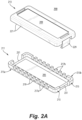
- the comb assembly 200, 600 can be configured to allow insertion and organization of the plurality of wires 97 in an open state (e.g., as shown in Figs. 2A and 6A ), and to retain the plurality of wires 97 in a relative position in a closed state (e.g., as shown in Fig. 1A and 5A ).
- the wire comb 100, 500 can include first indicia 103 (e.g., one or more markings, labels, etchings, raised structure) disposed within the comb assembly 200 on an interior surface 205, 605 of at least a portion of the comb assembly 200, 600.
- the first indicia 103 can be positioned to underlay the plurality of wires 97 to allow the wires to be organized over the first indicia 103 in accordance with the first indicia 103 in the open state.
- the wire comb 100, 500 can include second indicia 107 disposed on an outer surface 209, 609 of the comb assembly 200, 600.
- the second indicia 107 can be positioned to correspond to the plurality of wires 97 retained within the comb assembly 200, 600 to allow the wires 97 to be installed into terminals of a second device (e.g., a device 1195, 1295, 1395, 1495, 1595 as shown in Figs. 11G , 12G , 13F , 14E , and 15G to which the wires 97 are being migrated) in accordance with the second indicia 107.
- a second device e.g., a device 1195, 1295, 1395, 1495, 1595 as shown in Figs. 11G , 12G , 13F , 14E , and 15G to which the wires 97 are being migrated
- the first indicia 103 can be different than the second indicia 107 (e.g., where the first device has a different terminal arrangement and/or nomenclature than the second device). In certain embodiments, the first indicia 103 can be the same as the second indicia 107 (e.g., where the terminals and nomenclature for the second device are the same as the first device).
- the position of the wires 97 in the first indicia 103 can be such that the plurality of wires 97 are organized to match the relative position as in the terminal arrangement of the first device (e.g., as shown in the embodiments of first indicia 103, 1303, 1503 of Figs. 11A-15H ).
- the second indicia 1207, 1307, 1407, 1507 can include position instructions (e.g., one or more arrows as shown) for repositioning one or more wires of the plurality of wires 97 to a position that is the same or similar to the terminal arrangement of the second device.
- the first indicia 103 can be configured such that the plurality of wires 97 are organized in a different arrangement such that the arrangement is the same or similar to the terminal arrangement of the second device (e.g., as shown in the middle and right portions of the schematic diagram of Fig. 10 ).
- the wires 97 can be made to be straightened for installation into the second device if the terminal arrangement of the first device and the second device are different.
- the first indicia 103 can be configured to cause ordering of the plurality of wires 97 so that the wires 97 correlate to the second indicia 107 (whether straightened or otherwise) when the comb assembly 200 is in the closed state (e.g., in order to indicate the correct wires for installation in the corresponding terminals of the second device after the wires 97 are removed from the first device).
- the comb assembly 200, 600 can include a first housing portion 211, 611 and a second housing portion 213, 613 configured to assemble together.
- the first housing portion 211, 611 can include the interior surface 205, 605 having the first indicia 103.
- the first housing portion 211, 611 can define a rim structure 215, 615 (e.g., having segmented sides) extending away from the interior surface 205, 605.
- the rim structure 215, 615 can substantially form a tray, wherein the first indicia 205, 605 are disposed within the tray.
- the rim structure 215, 615 can include comb teeth 217a, 217b, 617a, 617b configured to receive a wire or the plurality of wires 99 between adjacent teeth (e.g., between adjacent teeth 217a).
- the comb teeth 217a, 217b, 617a, 617b can form the openings 201, 601 and/or a portion thereof.
- the comb teeth 217a, 217b, 617a, 617b of the first housing portion 211, 611 can form a large portion 219, 619 of the openings 211, 611 and the second housing portion 213, 613 can form a small portion 221 of the openings 211, 611.
- the second housing portion 213, 613 can include a similar tray shape (e.g., defined by a second rim structure as shown) to the first housing portion 211, 611 and define aligning low teeth that align with the comb teeth.
- the openings 211, 611 can be formed in any suitable proportion by the first housing portion 211, 611 and the second housing portion 213, 613 such that the plurality of wires 99 can be arranged relative to the first indicia 107.
- having larger portions 219, 619 of or all of the openings 211, 611 defined by the first housing portion 211, 611 can allow better lateral and/or frictional retaining of the wires 99 when being inserted into the first housing portion 211, 611.
- the small portions 221, 621 can be configured to allow accommodation for a larger size of wire. Certain embodiments may not include the small portions 221, 621.
- the rim structure 215, 615 can include a first rim portion 215a, 615a and a second rim portion 215b, 615b disposed on an opposite side of the interior surface 205, 605 relative to the first rim portion 215a, 251b.
- the first rim portion 215a, 251b can have first comb teeth 217a, 617a and the second rim potion 215b, 615b can have second comb teeth 217b, 617b.
- the first comb teeth 217a, 617a and second comb teeth 217b, 617b can be aligned to form a plurality of slots (e.g., pathways formed between opening portions 219, 619 for wires 99 to cross over the first indicia 107).
- the first indicia 103 can include a wire indication relative to each of the plurality of slots (e.g., text positioned between opposing portions 219, 619).
- the second housing portion 213, 613 can be configured to clip to the first housing portion 211, 611.
- the second housing portion 213, 613 can be hinged to the first housing portion 211, 611 (e.g., via a mechanical or living hinge connection).
- the second housing portion 213, 613 and the first housing portion 211, 611 can be separate pieces that assemble together (e.g., with one or more clips).
- the comb assembly 200, 600 can include a plurality of clips 229, 629a, 629b configured to connect the first housing portion 211, 611 to the second housing portion 213, 613.
- the plurality of clips 629a, 629b can include arrow clips (e.g., inward as shown in the embodiment of Fig. 1A , and/or outward as shown in the embodiment of Fig. 5A ).
- the first housing portion 611 and/or second housing portion 613 can include corresponding clip apertures 631a, 631b configured to receive the arrow clips. Any other suitable clip type is contemplated herein.
- the clip apertures 631a, 631b can be integrally formed with the first housing portion 611, and the arrow clips 629a, 629b can be integrally formed with the second housing portion 613. It is contemplated that the clips 629a, 629b and clip apertures 631a, 631b can be associated with either the first housing portion 611 or the second housing portion 613, or any combination thereof.
- the arrow clips 629a, 629b can be outer facing arrow clips as shown in the embodiments of Fig. 5A .
- the arrow clips 229 can be inner facing arrow clips 229 as shown in the embodiment of Fig. 1A .
- the clip apertures 231 can be recesses formed in the first housing portion 211 as opposed to an enclosed aperture as shown in the embodiment of Fig. 5A . Any suitable clip apertures are contemplated herein.
- the first housing portion 611 and/or the second housing portion 613 can include one or more orientation features configured to orient the first housing portion 611 relative to the second housing portion 613 when attached together in the closed position.
- the one or more orientation features can include one or more rabbet protrusions 625a, 625b on the first housing portion 611 or and/or second housing portion 613, and one or more corresponding rabbet recesses 627a, 627b on the other of the first housing portion 611 and/or the second housing portion 613 that are configured to receive the one or more rabbet protrusions 625a, 625b.
- the one or more rabbet protrusions 625a, 625b and/or rabbet recesses 627a, 627b can include a plurality of rabbet protrusions 625a, 625b and rabbet recesses 627a, 627b, e.g., as shown. At least two of the plurality of rabbet protrusions 625a, 625b can have different sizes and be positioned to require the first housing portion 211, 611 and the second housing portion 213, 613 to attach together in a predetermined orientation.
- one side of the second housing portion 613 can include longer rabbet protrusions 625a, and the opposite side can include shorter rabbet protrusions 625b, while one side of the first housing portion 611 can include longer rabbet recesses 627a, and the opposite side can include shorter rabbet recesses 627b to correspond to the different size rabbet protrusions 625a, 625b. It is contemplated that either or both of the first housing portion 611 or second housing portion 613 can include rabbet protrusions and/or rabbet recesses. Any number and/or arrangement of rabbet protrusions and recesses that cause orientation of the first housing portion 611 relative to the second housing portion 613 are contemplated herein.
- the one or more orientation features can be or include (e.g., with or without the rabbet protrusions and recesses) the plurality clips 629a, 629b such that the clips 629a, 629b have different sizes such that the first housing portion 611 and the second housing portion 613 connect together in a predetermined orientation (e.g., such that the clips allow only one way to clip the parts together).
- clip 629a can be smaller (e.g., less wide) than clip 629b.
- the clip apertures 631a, 631b can be similarly sized to receive their respective clip 629a, 629b.
- the clip 629b can be sized to not fit within the clip aperture 631a, preventing reverse attachment of the first housing portion 611 to the second housing portion 613.
- Certain embodiments can include a cushion 123 configured to compress against the wires 99 retained within the openings 201, 601.
- the cushion 123 can be made of any suitable soft and/or compressible material (e.g., foam, rubber, etc.) and can be sized to provide a compressive force to the wires 99.
- the wires 99 can be held tightly within the wire comb 100 and lateral movement/vibration of the wires 99 can be prevented.
- the cushion 123 can be adhered to the second housing portion 211, 611 and can extend past the small openings 221, 621 or second rim structure for example.
- first indicia 103 and the second indicia 107 can be relatively configured to cause straightening of the wires 99 for input into the second device.
- first indicia 103 and second indicia 107 can be sticker labels.
- a device conversion kit for replacing a first electrical device having a plurality of wires connected thereto can include a second electrical device having a plurality of wire terminals configured to be connected to the plurality of wires of the first device.
- the kit can also include a wire comb as disclosed herein, e.g., as described above (e.g., wherein the first indicia 103 include indicia associated with the first device, and the second indicia 107 include indicia associated with the second device).
- the kit can include a plurality of indicia to be applied to the comb assembly for various possible application (e.g., as shown in Figs. 9 and 10 ).
- a method can include organizing a plurality of wires within a wire comb (e.g., comb 100, 500) in accordance with first indicia on an interior surface of the wire comb, the first indicia associated with wire position and/or terminal nomenclature in a first device, closing the wire comb over the plurality of wires to retain the plurality of wires in a relative position to each other, removing the plurality of wires from the first device while the plurality of wires are held in the wire comb, and installing the plurality of wires into a second device in accordance with second indicia on an outer surface of the wire comb while the plurality of wires are held in the wire comb, the second indicia associated with wire position and/or terminal nomenclature in the second device.
- the method can also include removing the wire comb after installing the plurality of wires into the second device.
- a wire comb can include a first housing portion 211, 611 defining a rim structure extending away from an interior surface 205, 605.
- the rim structure can include comb teeth configured to receive a wire or the plurality of wires between adjacent teeth.
- the rim structure can form side walls of the first housing portion 211, 611 such that the first housing portion 211, 611 forms a tray shape having an interior surface 205, 605.
- the wire comb can include a second housing portion 213, 613 configured to assemble with the first housing portion 211, 611.
- the wire comb can be or include any other suitable wire comb disclosed herein, e.g., as described above.
- the wire comb can have any other suitable structure disclosed herein, e.g., as described above (e.g., without indicia).
- a wire comb for enabling faster wire exchange when migrating a plurality of electrical wires from at least one first device (e.g., device(s) being migrated from) to at least one second device (e.g., device(s) being migrated to) can include an upper portion (e.g., a second housing portion 213, 613 as disclosed herein) having an outer surface 209, 609 and an inner surface, the outer surface 209, 609 of the upper portion having an outer label with terminal position text associated with the plurality of electrical wires for the at least one second device (e.g., device(s) being migrated to), and the inner surface of the upper portion having a compression cushion disposed thereover.
- an upper portion e.g., a second housing portion 213, 613 as disclosed herein
- the outer surface 209, 609 of the upper portion having an outer label with terminal position text associated with the plurality of electrical wires for the at least one second device (e.g., device(s) being migrated to)
- the wire comb can include a lower portion (e.g., a first housing portion 211, 611 as disclosed herein) having an outer surface and an inner surface, the inner surface of the lower portion having an inner label with terminal position text associated with the plurality of electrical wires for the at least one first device.
- a lower portion e.g., a first housing portion 211, 611 as disclosed herein
- the inner surface of the lower portion having an inner label with terminal position text associated with the plurality of electrical wires for the at least one first device.
- the inner surface of the lower portion can also having a plurality of cavities (e.g., the opening portions as disclosed herein) formed therein, the plurality of cavities extending a predetermined depth from the inner surface to the outer surface of the lower portion and extending between first and second opposing sides of the lower portion, each of the plurality of cavities shaped to receive a respective electrical wire of the plurality of electrical wires, with the plurality of electrical wires capable of passing through the first and second opposing sides of the lower portion through the plurality of cavities.
- a plurality of cavities e.g., the opening portions as disclosed herein
- the upper portion of the wire comb can be configured to be removably coupled from the lower portion of the wire comb using at least one fastening means, and the compression cushion can be configured to exert a force on the plurality electrical wires to reduce or eliminate movement of the plurality of electrical wires in the wire comb when the plurality of wires are received in the plurality of cavities and the upper portion of the wire comb is coupled to the lower portion of the wire comb.
- the at least one fastening means can include at least one fastening mechanism integrated into at least one of the upper portion and the lower portion.
- the at least one fastening mechanism can include at least one snap latch (e.g., the arrow clips as disclosed above).
- the at least one fastening mechanism can include at least one hinge.
- the plurality of cavities can be configured to accommodate wires of various gauges.
- the wire comb can be molded or printed (or made with any other suitable method).
- the outer label can be printed, etched, or molded on the outer surface of the upper portion (or formed in any other suitable manner, e.g., stamped, integrally formed, etc.).
- the inner label can be printed or etched on the inner surface of the lower portion.
- at least one aspect of the terminal position text associated with the plurality of electrical wires for the at least one second device can be different from the terminal position text associated with the plurality of electrical wires for the at least one first device.
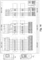
- Fig. 9 is a schematic diagram showing an embodiment of a plurality of indicia (e.g., labels) for different applications and for use with wire combs disclosed herein.
- Fig. 10 is a schematic diagram showing the indicia of Fig. 9 being used to migrate wires from a first device 1097 to a second device 1095.
- the indicia can be one or more labels (e.g., with adhesive) that can be placed on or in the comb housing.
- Various labels can be provided with a wire comb for a user to apply for a specific application (e.g., for specific devices and/or for IO types such as digital, analog, and relay).
- each set can include first indicia (e.g., labels A) and second indicia (e.g., labels B).
- third indicia e.g., labels C
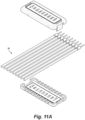
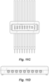
- Figs. 11A-11H illustrate an embodiment of a wire comb in accordance with this disclosure being installed over a plurality of wires ( Figs. 11A , 11B , 11C, and 11D ) when the plurality of wires are connected to a first device ( Fig. 11E ), showing an embodiment of first indicia 103 ( Fig. 11F ) on an inside of the comb assembly 200, 600, and an embodiment of second device ( Fig. 11G ) and second indicia 107 ( Fig. 11H ) on an outside of the comb assembly 200, 600 correlating to terminals of the second device, wherein all wires are shown in a same position as organized from the first device.
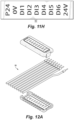
- Figs. 12A-12H illustrate an embodiment of a wire comb in accordance with this disclosure being installed over a plurality of wires ( Figs. 12A , 12B , 12C, and 12D ) when the plurality of wires are connected to a first device ( Fig. 12E ), showing an embodiment of first indicia 103 ( Fig. 12F ) on an inside of the comb assembly 200, 600, and an embodiment of second device ( Fig. 12G ) and second indicia 107 ( Fig. 12H ) on an outside of the comb assembly 200, 600 correlating to terminals of the second device, wherein the second device requires repositioning of at least one wire (already shown bent into position in Figs. 12A-12D ) for which the second indicia 107 includes an arrow to indicate where to reposition the wire.
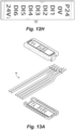
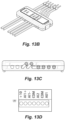
- Figs. 13A-13G illustrate an embodiment of a wire comb in accordance with this disclosure being installed over a plurality of wires ( Figs. 13A , 13B, and 13C ) when the plurality of wires are connected to a first device ( Fig. 13D ), showing an embodiment of first indicia 103 ( Fig. 13E ) on an inside of the comb assembly 200, 600, and an embodiment of second device ( Fig. 13F ) and second indicia 107 ( Fig. 13G ) on an outside of the comb assembly 200, 600 correlating to terminals of the second device, wherein the second device requires repositioning of at least one wire (already shown bent into position in Figs. 12A-12D ) for which the second indicia 107 includes arrows to indicate where to reposition the wires.
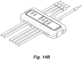
- Figs. 14A-14F illustrate an embodiment of a wire comb in accordance with this disclosure being installed over a plurality of wires ( Figs. 14A , 14B , 14C, and 14D ) when the plurality of wires are connected to a first device (not shown), showing an embodiment of first indicia 103 (shown in Fig. 12A ) on an inside of the comb assembly 200, 600, and an embodiment of second device ( Fig. 14E ) and second indicia 107 ( Fig. 14F ) on an outside of the comb assembly 200, 600 correlating to terminals of the second device, wherein the second device requires repositioning of at least one wire (already shown bent into position in Figs. 14A-14D ) for which the second indicia 107 includes an arrow to indicate where to reposition the wire.
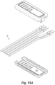
- Figs. 15A-15H illustrate an embodiment of a wire comb in accordance with this disclosure being installed over a plurality of wires ( Figs. 15A , 15B , 15C, and 15D ) when the plurality of wires are connected to a first device ( Fig. 15E ), showing an embodiment of first indicia 103 ( Fig. 15F ) on an inside of the comb assembly 200, 600, and an embodiment of second device ( Fig. 15G ) and second indicia 107 ( Fig. 15H ) on an outside of the comb assembly 200, 600 correlating to terminals of the second device, wherein the second device requires repositioning of at least one wire (already shown bent into position in Figs. 12A-12D ) for which the second indicia 107 includes an arrow to indicate where to reposition the wire.
- Embodiments can include a snap together wire comb (e.g., for drive evolution to newer drives).
- Embodiments can include a wire comb having and outer wire comb label, a wire comb snap latch part (e.g., made from polycarbonate), a foam cushion with adhesive backing, an inner wire comb label, and a wire comb snap receiver made (e.g., from polycarbonate )with the inner wire comb label disposed therein.
- the foam cushion can be adhered to an inner surface of the snap latch part (e.g., the second housing portion disclosed above).
- Embodiments of a method can include opening the wire comb and holding the base support, inserting the wire comb behind the wires, selecting the right slot for each wire following the marks and terminal identification, closing the wire comb cover, screwing out all wires from the old terminal, remove the old device and install the new device, identifying the terminal marks for each wire in the terminal, and screwing in each wire following the mark identification.
- the method can include verify if each wire is well tight.
- Embodiments of a method can include removing the wire comb cover, and then removing the base support.
- Embodiments of a wire comb can hold existing wires in the right position for the new device. When opened, the user can see the inner label with terminal positions for the old device. When closed, the user can see the outer label with terminal positions for the new device.
- the wires can be secured in the wire comb during installation to prevent unwanted movement of the wires.
- Embodiments enable faster exchange of wires between old and new devices (e.g., to reduce installation times). Embodiments reduce the likelihood of mixing up wires (e.g., to increase safety of installation). Embodiments can hold wires in place during installation.
- Embodiments of a wire comb can include labels with terminal positions for an old device and new device, accounting for differences in terminal positions and naming conventions between the old device and the new device.
- Embodiments can be made of plastic or other suitable insulating material to be electrical insulated.
- any numerical values disclosed herein can be exact values or can be values within a range. Further, any terms of approximation (e.g., “about”, “approximately”, “around”) used in this disclosure can mean the stated value within a range. For example, in certain embodiments, the range can be within (plus or minus) 20%, or within 10%, or within 5%, or within 2%, or within any other suitable percentage or number as appreciated by those having ordinary skill in the art (e.g., for known tolerance limits or error ranges).
- a reference to "A and/or B", when used in conjunction with open-ended language such as “comprising” can refer, in one embodiment, to A only (optionally including elements other than B); in another embodiment, to B only (optionally including elements other than A); in yet another embodiment, to both A and B (optionally including other elements); etc.
Landscapes
- Engineering & Computer Science (AREA)
- Architecture (AREA)
- Civil Engineering (AREA)
- Structural Engineering (AREA)
- Details Of Connecting Devices For Male And Female Coupling (AREA)
Abstract
Description
- This disclosure relates to wire migration in electrical systems.
- Migrating wires from an old device to a new device can be a very tedious and time-consuming process. For example, with devices typically including a plurality of wires, and many of the plurality of wires having the same or similar colorings, it can be difficult to disconnect wires from the old device and correctly connect the wires to the new device. Labeling each of the wires can be a time-consuming process. Additionally, incorrect wire connections can cause safety hazards, and potentially cause damage to devices and result in lost time. Installing the wrong cable can present an electricity risk or unexpected/unwanted behavior.
- Conventional methods and systems have generally been considered satisfactory for their intended purpose. However, there is still a need in the art for improved wire migration devices, systems, and methods. The present disclosure provides a solution for this need.
- A wire comb can include a comb assembly defining a plurality of openings configured to organize and retain a plurality of wires associated with a first device. The comb assembly can be configured to allow insertion and organization of the plurality of wires in an open state, and to retain the plurality of wires in a relative position in a closed state. The wire comb can include first indicia disposed within the comb assembly on an interior surface of at least a portion of the comb assembly. The first indicia can be positioned to underlay the plurality of wires to allow the wires to be organized over the first indicia in accordance with the first indicia in the open state. The wire comb can include second indicia disposed on an outer surface of the comb assembly. The second indicia can be positioned to correspond to the plurality of wires retained within the comb assembly to allow the wires to be installed into terminals of a second device in accordance with the second indicia.
- The first indicia can be different than the second indicia (e.g., where the first device has a different terminal arrangement and/or nomenclature than the second device). In certain embodiments, the first indicia can be the same as the second indicia.
- In certain embodiments, the comb assembly can include a first housing portion and a second housing portion configured to assemble together. The first housing portion can include the interior surface having the first indicia.
- The first housing portion can define a rim structure extending away from the interior surface. The rim structure can include comb teeth configured to receive a wire or the plurality of wires between adjacent teeth. In certain embodiments, the rim structure can include a first rim portion and a second rim portion disposed on an opposite side of the interior surface relative to the first rim portion. The first rim portion can have first comb teeth and the second rim potion can have second comb teeth.
- The first comb teeth and second comb teeth can be aligned to form a plurality of slots. The first indicia can include a wire indication relative to each of the plurality of slots. The second housing portion can be configured to clip to the first housing portion.
- The first housing portion and/or the second housing portion can include one or more orientation features configured to orient the first housing portion relative to the second housing portion when attached together in the closed position. The comb assembly can include a plurality of clips configured to connect the first housing portion to the second housing portion. In certain embodiments, the one or more orientation features can include the plurality clips such that the clips have different sizes such that the first housing portion and the second housing portion connect together in a predetermined orientation.
- In certain embodiments, the plurality of clips can include arrow clips and corresponding clip apertures configured to receive the arrow clips. Any suitable clip type is contemplated herein. The clip apertures can be integrally formed with the first housing portion, and the arrow clips can be integrally formed with the second housing portion. It is contemplated that the clips and clip apertures can be associated with either the first housing portion or the second housing portion.
- In certain embodiments, the arrow clips can be outer facing arrow clips. In certain embodiments, the arrow clips can be inner facing arrow clips.
- In certain embodiments, the one or more orientation features can include one or more rabbet protrusions on the first housing portion or and/or second housing portion, and one or more corresponding rabbet recesses on the other of the first housing portion and/or the second housing portion that are configured to receive the one or more rabbet protrusions. The one or more rabbet protrusions and/or rabbet recesses can include a plurality of rabbet protrusions and rabbet recesses. At least two of the plurality of rabbet protrusions can have different sizes and be positioned to require the first housing portion and the second housing portion to attach together in a predetermined orientation.
- In certain embodiments, the first indicia and the second indicia can be relatively configured to cause straightening of the wires for input into the second device. In certain embodiments, the first indicia and second indicia can be sticker labels.
- In accordance with at least one aspect of this disclosure, a device conversion kit for replacing a first electrical device having a plurality of wires connected thereto can include a second electrical device having a plurality of wire terminals configured to be connected to the plurality of wires of the first device. The kit can also include a wire comb as disclosed herein, e.g., as described above (e.g., wherein the first indicia include indicia associated with the first device, and the second indicia include indicia associated with the second device).
- In accordance with at least one aspect of this disclosure, a method can include organizing a plurality of wires within a wire comb in accordance with first indicia on an interior surface of the wire comb, the first indicia associated with wire position and/or terminal nomenclature in a first device, closing the wire comb over the plurality of wires to retain the plurality of wires in a relative position to each other, removing the plurality of wires from the first device while the plurality of wires are held in the wire comb, and installing the plurality of wires into a second device in accordance with second indicia on an outer surface of the wire comb while the plurality of wires are held in the wire comb, the second indicia associated with wire position and/or terminal nomenclature in the second device. In certain embodiments, the method can also include removing the wire comb after installing the plurality of wires into the second device.
- In accordance with at least one aspect of this disclosure, a wire comb can include a first housing portion defining a rim structure extending away from an interior surface. The rim structure can include comb teeth configured to receive a wire or the plurality of wires between adjacent teeth. The rim structure can form side walls of the first housing portion such that the first housing portion forms a tray shape having an interior surface. The wire comb can include a second housing portion configured to assemble with the first housing portion. The wire comb can be or include any other suitable wire comb disclosed herein, e.g., as described above. The wire comb can have any other suitable structure disclosed herein, e.g., as described above (e.g., without indicia).
- In accordance with at least one aspect of this disclosure, a wire comb for enabling faster wire exchange when migrating a plurality of electrical wires from at least one first device (e.g., device(s) being migrated from) to at least one second device (e.g., device(s) being migrated to) can include an upper portion (e.g., a second housing portion as disclosed herein) having an outer surface and an inner surface, the outer surface of the upper portion having an outer label with terminal position text associated with the plurality of electrical wires for the at least one second device (e.g., device(s) being migrated to), and the inner surface of the upper portion having a compression cushion disposed thereover. The wire comb can include a lower portion (e.g., a first housing portion as disclosed herein) having an outer surface and an inner surface, the inner surface of the lower portion having an inner label with terminal position text associated with the plurality of electrical wires for the at least one first device. The inner surface of the lower portion can also having a plurality of cavities formed therein, the plurality of cavities extending a predetermined depth from the inner surface to the outer surface of the lower portion and extending between first and second opposing sides of the lower portion, each of the plurality of cavities shaped to receive a respective electrical wire of the plurality of electrical wires, with the plurality of electrical wires capable of passing through the first and second opposing sides of the lower portion through the plurality of cavities. The upper portion of the wire comb can be configured to be removably coupled from the lower portion of the wire comb using at least one fastening means, and the compression cushion can be configured to exert a force on the plurality electrical wires to reduce or eliminate movement of the plurality of electrical wires in the wire comb when the plurality of wires are received in the plurality of cavities and the upper portion of the wire comb is coupled to the lower portion of the wire comb.
- The at least one fastening means can include at least one fastening mechanism integrated into at least one of the upper portion and the lower portion. The at least one fastening mechanism can include at least one snap latch. In certain embodiments, the at least one fastening mechanism can include at least one hinge.
- The plurality of cavities can be configured to accommodate wires of various gauges. The wire comb can be molded or printed. The outer label can be printed, etched, or molded on the outer surface of the upper portion. The inner label can be printed or etched on the inner surface of the lower portion. In certain embodiments, at least one aspect of the terminal position text associated with the plurality of electrical wires for the at least one second device can be different from the terminal position text associated with the plurality of electrical wires for the at least one first device.
- These and other features of the embodiments of the subject disclosure will become more readily apparent to those skilled in the art from the following detailed description taken in conjunction with the drawings.
- So that those skilled in the art to which the subject disclosure appertains will readily understand how to make and use the devices and methods of the subject disclosure without undue experimentation, embodiments thereof will be described in detail herein below with reference to certain figures, wherein:
-
Fig. 1A is a perspective view of an embodiment of a wire comb in accordance with this disclosure, shown assembled; -
Fig. 1B is a side elevation view of the embodiment ofFig. 1A ; -
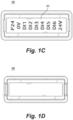
Fig. 1C is a plan view of the embodiment ofFig. 1A ; -
Fig. 1D is a reverse plan view of the embodiment ofFig. 1C ; -
Fig. 1E is an exploded view of the embodiment ofFig. 1A ; -
Fig. 2A is an exploded view of a comb assembly of the embodiment of a wire combFig. 1A ; -
Fig. 2B is a reverse exploded view of the comb assembly as shown inFig. 2A ; -
Fig. 3A is a plan view of a first housing portion of the embodiment of a comb assembly ofFig. 2A ; -
Fig. 3B is an elevation view of the first housing portion ofFig. 3A ; -
Fig. 3C is a cross-sectional view of the first housing portion ofFig. 3A ; -
Fig. 3D is a cross-sectional view of the embodiment of the first housing portion ofFig. 3A ; -
Fig. 4A is a plan view of a second housing portion of the embodiment of a comb assembly ofFig. 2A ; -
Fig. 4B is an elevation view of the second housing portion ofFig. 4A ; -
Fig. 4C is a cross-sectional view of the second housing portion ofFig. 4A ; -
Fig. 4D is a cross-sectional view of the embodiment of the second housing portion ofFig. 3A ; -
Fig. 4E is detail cross-sectional view of the embodiment of the second housing portion as shown inFig. 4A ; -
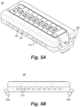
Fig. 5A is a perspective view of another embodiment of a wire comb in accordance with this disclosure, shown assembled; -
Fig. 5B is a side elevation view of the embodiment ofFig. 5A ; -
Fig. 5C is a plan view of the embodiment ofFig. 5A ; -
Fig. 5D is a side elevation view of the embodiment ofFig. 5A ; -
Fig. 5E is a reverse side elevation view of the embodiment ofFig. 5D ; -
Fig. 5F is an exploded view of the embodiment ofFig. 5A ; -
Fig. 6A is an exploded view of a comb assembly of the embodiment of a wire combFig. 5A ; -
Fig. 6B is a reverse exploded view of the comb assembly as shown inFig. 6A ; -
Fig. 6C is a side exploded view of the comb assembly as shown inFig. 6A ; -
Fig. 7A is a perspective view of a first housing portion of the embodiment of a comb assembly ofFig. 6A ; -
Fig. 7B is a plan view of the first housing portion ofFig. 6A ; -
Fig. 8A is a perspective view of a second housing portion of the embodiment of a comb assembly ofFig. 6A ; -
Fig. 8B is a plan view of the second housing portion ofFig. 6A ; -
Fig. 8C is a side elevation view of the second housing portion ofFig. 6A ; -
Fig. 9 is a schematic diagram showing an embodiment of a plurality of indicia (e.g., labels) for different applications and for use with wire combs disclosed herein; -
Fig. 10 is a schematic diagram showing the indicia ofFig. 9 being used to migrate wires from a first device to a second device; -
Figs. 11A-11H illustrate an embodiment of a wire comb in accordance with this disclosure being installed over a plurality of wires (Figs. 11A ,11B ,11C, and 11D ) when the plurality of wires are connected to a first device (Fig. 11E ), showing an embodiment of first indicia (Fig. 11F ) on an inside of the comb assembly, and an embodiment of second device (Fig. 11G ) and second indicia (Fig. 11H ) on an outside of the comb assembly correlating to terminals of the second device, wherein all wires are shown in a same position as organized from the first device; -
Figs. 12A-12H illustrate an embodiment of a wire comb in accordance with this disclosure being installed over a plurality of wires (Figs. 12A ,12B ,12C, and 12D ) when the plurality of wires are connected to a first device (Fig. 12E ), showing an embodiment of first indicia (Fig. 12F ) on an inside of the comb assembly, and an embodiment of second device (Fig. 12G ) and second indicia (Fig. 12H ) on an outside of the comb assembly correlating to terminals of the second device, wherein the second device requires repositioning of at least one wire (already shown bent into position inFigs. 12A-12D ) for which the second indicia includes an arrow to indicate where to reposition the wire; -
Figs. 13A-13G illustrate an embodiment of a wire comb in accordance with this disclosure being installed over a plurality of wires (Figs. 13A ,13B, and 13C ) when the plurality of wires are connected to a first device (Fig. 13D ), showing an embodiment of first indicia (Fig. 13E ) on an inside of the comb assembly, and an embodiment of second device (Fig. 13F ) and second indicia (Fig. 13G ) on an outside of the comb assembly correlating to terminals of the second device, wherein the second device requires repositioning of at least one wire (already shown bent into position inFigs. 12A-12D ) for which the second indicia includes arrows to indicate where to reposition the wires; -
Figs. 14A-14F illustrate an embodiment of a wire comb in accordance with this disclosure being installed over a plurality of wires (Figs. 14A ,14B ,14C, and 14D ) when the plurality of wires are connected to a first device (not shown), showing an embodiment of first indicia (shown inFig. 12A ) on an inside of the comb assembly, and an embodiment of second device (Fig. 14E ) and second indicia (Fig. 14F ) on an outside of the comb assembly correlating to terminals of the second device, wherein the second device requires repositioning of at least one wire (already shown bent into position inFigs. 14A-14D ) for which the second indicia includes an arrow to indicate where to reposition the wire; and -
Figs. 15A-15H illustrate an embodiment of a wire comb in accordance with this disclosure being installed over a plurality of wires (Figs. 15A ,15B ,15C, and 15D ) when the plurality of wires are connected to a first device (Fig. 15E ), showing an embodiment of first indicia (Fig. 15F ) on an inside of the comb assembly, and an embodiment of second device (Fig. 15G ) and second indicia (Fig. 15H ) on an outside of the comb assembly correlating to terminals of the second device, wherein the second device requires repositioning of at least one wire (already shown bent into position inFigs. 12A-12D ) for which the second indicia includes an arrow to indicate where to reposition the wire. - Reference will now be made to the drawings wherein like reference numerals identify similar structural features or aspects of the subject disclosure. For purposes of explanation and illustration, and not limitation, an illustrative view of an embodiment of a wire comb in accordance with the disclosure is shown in
Fig. 1A and is designated generally byreference character 100. Other embodiments and/or aspects of this disclosure are shown inFigs. 1B-15H . - Referring to
Figs. 1A-8C , awire comb comb assembly comb assembly openings wires 99 as shown inFigs. 11A-15H ) associated with a first device (e.g., adevice Figs. 11E ,12E ,13D ,15E that the wires are attached to and being migrated from). Thecomb assembly Figs. 2A and6A ), and to retain the plurality of wires 97 in a relative position in a closed state (e.g., as shown inFig. 1A and5A ). - As shown in
Fig. 1E and5F , thewire comb comb assembly 200 on aninterior surface comb assembly first indicia 103 can be positioned to underlay the plurality of wires 97 to allow the wires to be organized over thefirst indicia 103 in accordance with thefirst indicia 103 in the open state. - The
wire comb second indicia 107 disposed on anouter surface comb assembly second indicia 107 can be positioned to correspond to the plurality of wires 97 retained within thecomb assembly device Figs. 11G ,12G ,13F ,14E , and15G to which the wires 97 are being migrated) in accordance with thesecond indicia 107. - The
first indicia 103 can be different than the second indicia 107 (e.g., where the first device has a different terminal arrangement and/or nomenclature than the second device). In certain embodiments, thefirst indicia 103 can be the same as the second indicia 107 (e.g., where the terminals and nomenclature for the second device are the same as the first device). - In certain embodiments, the position of the wires 97 in the
first indicia 103 can be such that the plurality of wires 97 are organized to match the relative position as in the terminal arrangement of the first device (e.g., as shown in the embodiments offirst indicia Figs. 11A-15H ). In such embodiments, e.g., as shown in the embodiments ofFigs. 12A-15H , thesecond indicia - In certain embodiments, e.g., the
first indicia 103 can be configured such that the plurality of wires 97 are organized in a different arrangement such that the arrangement is the same or similar to the terminal arrangement of the second device (e.g., as shown in the middle and right portions of the schematic diagram ofFig. 10 ). In this regard, the wires 97 can be made to be straightened for installation into the second device if the terminal arrangement of the first device and the second device are different. In any case, thefirst indicia 103 can be configured to cause ordering of the plurality of wires 97 so that the wires 97 correlate to the second indicia 107 (whether straightened or otherwise) when thecomb assembly 200 is in the closed state (e.g., in order to indicate the correct wires for installation in the corresponding terminals of the second device after the wires 97 are removed from the first device). - In certain embodiments, the
comb assembly first housing portion second housing portion first housing portion interior surface first indicia 103. - The
first housing portion rim structure 215, 615 (e.g., having segmented sides) extending away from theinterior surface rim structure first indicia - The
rim structure teeth wires 99 between adjacent teeth (e.g., betweenadjacent teeth 217a). Thecomb teeth openings Figs. 1A-8C , thecomb teeth first housing portion large portion openings second housing portion small portion 221 of theopenings second housing portion first housing portion openings first housing portion second housing portion wires 99 can be arranged relative to thefirst indicia 107. In this regard, havinglarger portions openings first housing portion wires 99 when being inserted into thefirst housing portion small portions small portions - In certain embodiments, the
rim structure first rim portion 215a, 615a and asecond rim portion 215b, 615b disposed on an opposite side of theinterior surface first rim portion 215a, 251b. Thefirst rim portion 215a, 251b can havefirst comb teeth second rim potion 215b, 615b can havesecond comb teeth - The
first comb teeth second comb teeth portions wires 99 to cross over the first indicia 107). As shown, thefirst indicia 103 can include a wire indication relative to each of the plurality of slots (e.g., text positioned between opposingportions 219, 619). - The
second housing portion first housing portion second housing portion first housing portion 211, 611 (e.g., via a mechanical or living hinge connection). As shown, in certain embodiments thesecond housing portion first housing portion - The
comb assembly clips first housing portion second housing portion clips Fig. 1A , and/or outward as shown in the embodiment ofFig. 5A ). In certain embodiments, e.g., as shown inFigs. 5A-8C , thefirst housing portion 611 and/orsecond housing portion 613 can includecorresponding clip apertures clip apertures first housing portion 611, and thearrow clips second housing portion 613. It is contemplated that theclips clip apertures first housing portion 611 or thesecond housing portion 613, or any combination thereof. - In certain embodiments, the
arrow clips Fig. 5A . In certain embodiments, the arrow clips 229 can be inner facing arrow clips 229 as shown in the embodiment ofFig. 1A . As shown in the embodiment ofFig. 1A , theclip apertures 231 can be recesses formed in thefirst housing portion 211 as opposed to an enclosed aperture as shown in the embodiment ofFig. 5A . Any suitable clip apertures are contemplated herein. - Referring to
Figs. 5F-8C , in certain embodiments, thefirst housing portion 611 and/or thesecond housing portion 613 can include one or more orientation features configured to orient thefirst housing portion 611 relative to thesecond housing portion 613 when attached together in the closed position. In certain embodiments, the one or more orientation features can include one ormore rabbet protrusions first housing portion 611 or and/orsecond housing portion 613, and one or morecorresponding rabbet recesses first housing portion 611 and/or thesecond housing portion 613 that are configured to receive the one ormore rabbet protrusions more rabbet protrusions rabbet recesses rabbet recesses first housing portion second housing portion second housing portion 613 can include longer rabbet protrusions 625a, and the opposite side can includeshorter rabbet protrusions 625b, while one side of thefirst housing portion 611 can includelonger rabbet recesses 627a, and the opposite side can include shorter rabbet recesses 627b to correspond to the differentsize rabbet protrusions first housing portion 611 orsecond housing portion 613 can include rabbet protrusions and/or rabbet recesses. Any number and/or arrangement of rabbet protrusions and recesses that cause orientation of thefirst housing portion 611 relative to thesecond housing portion 613 are contemplated herein. - In certain embodiments, the one or more orientation features can be or include (e.g., with or without the rabbet protrusions and recesses) the plurality clips 629a, 629b such that the
clips first housing portion 611 and thesecond housing portion 613 connect together in a predetermined orientation (e.g., such that the clips allow only one way to clip the parts together). For example, as shown inFigs. 5D and5E ,clip 629a can be smaller (e.g., less wide) thanclip 629b. Theclip apertures respective clip clip 629b can be sized to not fit within theclip aperture 631a, preventing reverse attachment of thefirst housing portion 611 to thesecond housing portion 613. - Certain embodiments can include a
cushion 123 configured to compress against thewires 99 retained within theopenings cushion 123 can be made of any suitable soft and/or compressible material (e.g., foam, rubber, etc.) and can be sized to provide a compressive force to thewires 99. In this regard, thewires 99 can be held tightly within thewire comb 100 and lateral movement/vibration of thewires 99 can be prevented. In certain embodiments, thecushion 123 can be adhered to thesecond housing portion small openings - In certain embodiments, the
first indicia 103 and thesecond indicia 107 can be relatively configured to cause straightening of thewires 99 for input into the second device. In certain embodiments, thefirst indicia 103 andsecond indicia 107 can be sticker labels. - In accordance with at least one aspect of this disclosure, a device conversion kit for replacing a first electrical device having a plurality of wires connected thereto can include a second electrical device having a plurality of wire terminals configured to be connected to the plurality of wires of the first device. The kit can also include a wire comb as disclosed herein, e.g., as described above (e.g., wherein the
first indicia 103 include indicia associated with the first device, and thesecond indicia 107 include indicia associated with the second device). The kit can include a plurality of indicia to be applied to the comb assembly for various possible application (e.g., as shown inFigs. 9 and10 ). - In accordance with at least one aspect of this disclosure, a method can include organizing a plurality of wires within a wire comb (e.g.,
comb 100, 500) in accordance with first indicia on an interior surface of the wire comb, the first indicia associated with wire position and/or terminal nomenclature in a first device, closing the wire comb over the plurality of wires to retain the plurality of wires in a relative position to each other, removing the plurality of wires from the first device while the plurality of wires are held in the wire comb, and installing the plurality of wires into a second device in accordance with second indicia on an outer surface of the wire comb while the plurality of wires are held in the wire comb, the second indicia associated with wire position and/or terminal nomenclature in the second device. In certain embodiments, the method can also include removing the wire comb after installing the plurality of wires into the second device. - In accordance with at least one aspect of this disclosure, a wire comb can include a
first housing portion interior surface first housing portion first housing portion interior surface second housing portion first housing portion - In accordance with at least one aspect of this disclosure, a wire comb for enabling faster wire exchange when migrating a plurality of electrical wires from at least one first device (e.g., device(s) being migrated from) to at least one second device (e.g., device(s) being migrated to) can include an upper portion (e.g., a
second housing portion outer surface outer surface first housing portion - The at least one fastening means can include at least one fastening mechanism integrated into at least one of the upper portion and the lower portion. The at least one fastening mechanism can include at least one snap latch (e.g., the arrow clips as disclosed above). In certain embodiments, the at least one fastening mechanism can include at least one hinge.
- The plurality of cavities can be configured to accommodate wires of various gauges. In certain embodiments, the wire comb can be molded or printed (or made with any other suitable method). The outer label can be printed, etched, or molded on the outer surface of the upper portion (or formed in any other suitable manner, e.g., stamped, integrally formed, etc.). The inner label can be printed or etched on the inner surface of the lower portion. In certain embodiments, at least one aspect of the terminal position text associated with the plurality of electrical wires for the at least one second device can be different from the terminal position text associated with the plurality of electrical wires for the at least one first device.
-
Fig. 9 is a schematic diagram showing an embodiment of a plurality of indicia (e.g., labels) for different applications and for use with wire combs disclosed herein.Fig. 10 is a schematic diagram showing the indicia ofFig. 9 being used to migrate wires from afirst device 1097 to asecond device 1095. As shown, the indicia can be one or more labels (e.g., with adhesive) that can be placed on or in the comb housing. Various labels can be provided with a wire comb for a user to apply for a specific application (e.g., for specific devices and/or for IO types such as digital, analog, and relay). As shown, each set can include first indicia (e.g., labels A) and second indicia (e.g., labels B). In certain embodiments, third indicia (e.g., labels C) can be includes to inform which devices the labels apply to for the proper application. -
Figs. 11A-11H illustrate an embodiment of a wire comb in accordance with this disclosure being installed over a plurality of wires (Figs. 11A ,11B ,11C, and 11D ) when the plurality of wires are connected to a first device (Fig. 11E ), showing an embodiment of first indicia 103 (Fig. 11F ) on an inside of thecomb assembly Fig. 11G ) and second indicia 107 (Fig. 11H ) on an outside of thecomb assembly -
Figs. 12A-12H illustrate an embodiment of a wire comb in accordance with this disclosure being installed over a plurality of wires (Figs. 12A ,12B ,12C, and 12D ) when the plurality of wires are connected to a first device (Fig. 12E ), showing an embodiment of first indicia 103 (Fig. 12F ) on an inside of thecomb assembly Fig. 12G ) and second indicia 107 (Fig. 12H ) on an outside of thecomb assembly Figs. 12A-12D ) for which thesecond indicia 107 includes an arrow to indicate where to reposition the wire. -
Figs. 13A-13G illustrate an embodiment of a wire comb in accordance with this disclosure being installed over a plurality of wires (Figs. 13A ,13B, and 13C ) when the plurality of wires are connected to a first device (Fig. 13D ), showing an embodiment of first indicia 103 (Fig. 13E ) on an inside of thecomb assembly Fig. 13F ) and second indicia 107 (Fig. 13G ) on an outside of thecomb assembly Figs. 12A-12D ) for which thesecond indicia 107 includes arrows to indicate where to reposition the wires. -
Figs. 14A-14F illustrate an embodiment of a wire comb in accordance with this disclosure being installed over a plurality of wires (Figs. 14A ,14B ,14C, and 14D ) when the plurality of wires are connected to a first device (not shown), showing an embodiment of first indicia 103 (shown inFig. 12A ) on an inside of thecomb assembly Fig. 14E ) and second indicia 107 (Fig. 14F ) on an outside of thecomb assembly Figs. 14A-14D ) for which thesecond indicia 107 includes an arrow to indicate where to reposition the wire. -
Figs. 15A-15H illustrate an embodiment of a wire comb in accordance with this disclosure being installed over a plurality of wires (Figs. 15A ,15B ,15C, and 15D ) when the plurality of wires are connected to a first device (Fig. 15E ), showing an embodiment of first indicia 103 (Fig. 15F ) on an inside of thecomb assembly Fig. 15G ) and second indicia 107 (Fig. 15H ) on an outside of thecomb assembly Figs. 12A-12D ) for which thesecond indicia 107 includes an arrow to indicate where to reposition the wire. - Embodiments can include a snap together wire comb (e.g., for drive evolution to newer drives). Embodiments can include a wire comb having and outer wire comb label, a wire comb snap latch part (e.g., made from polycarbonate), a foam cushion with adhesive backing, an inner wire comb label, and a wire comb snap receiver made (e.g., from polycarbonate )with the inner wire comb label disposed therein. The foam cushion can be adhered to an inner surface of the snap latch part (e.g., the second housing portion disclosed above).
- Embodiments of a method can include opening the wire comb and holding the base support, inserting the wire comb behind the wires, selecting the right slot for each wire following the marks and terminal identification, closing the wire comb cover, screwing out all wires from the old terminal, remove the old device and install the new device, identifying the terminal marks for each wire in the terminal, and screwing in each wire following the mark identification. The method can include verify if each wire is well tight. Embodiments of a method can include removing the wire comb cover, and then removing the base support.
- Embodiments of a wire comb can hold existing wires in the right position for the new device. When opened, the user can see the inner label with terminal positions for the old device. When closed, the user can see the outer label with terminal positions for the new device. The wires can be secured in the wire comb during installation to prevent unwanted movement of the wires.
- Embodiments enable faster exchange of wires between old and new devices (e.g., to reduce installation times). Embodiments reduce the likelihood of mixing up wires (e.g., to increase safety of installation). Embodiments can hold wires in place during installation. Embodiments of a wire comb can include labels with terminal positions for an old device and new device, accounting for differences in terminal positions and naming conventions between the old device and the new device. Embodiments can be made of plastic or other suitable insulating material to be electrical insulated.
- Those having ordinary skill in the art understand that any numerical values disclosed herein can be exact values or can be values within a range. Further, any terms of approximation (e.g., "about", "approximately", "around") used in this disclosure can mean the stated value within a range. For example, in certain embodiments, the range can be within (plus or minus) 20%, or within 10%, or within 5%, or within 2%, or within any other suitable percentage or number as appreciated by those having ordinary skill in the art (e.g., for known tolerance limits or error ranges).
- The articles "a", "an", and "the" as used herein and in the appended claims are used herein to refer to one or to more than one (i.e., to at least one) of the grammatical object of the article unless the context clearly indicates otherwise. By way of example, "an element" means one element or more than one element.
- The phrase "and/or," as used herein in the specification and in the claims, should be understood to mean "either or both" of the elements so conjoined, i.e., elements that are conjunctively present in some cases and disjunctively present in other cases. Multiple elements listed with "and/or" should be construed in the same fashion, i.e., "one or more" of the elements so conjoined. Other elements may optionally be present other than the elements specifically identified by the "and/or" clause, whether related or unrelated to those elements specifically identified. Thus, as a non-limiting example, a reference to "A and/or B", when used in conjunction with open-ended language such as "comprising" can refer, in one embodiment, to A only (optionally including elements other than B); in another embodiment, to B only (optionally including elements other than A); in yet another embodiment, to both A and B (optionally including other elements); etc.
- As used herein in the specification and in the claims, "or" should be understood to have the same meaning as "and/or" as defined above. For example, when separating items in a list, "or" or "and/or" shall be interpreted as being inclusive, i.e., the inclusion of at least one, but also including more than one, of a number or list of elements, and, optionally, additional unlisted items. Only terms clearly indicated to the contrary, such as "only one of' or "exactly one of," or, when used in the claims, "consisting of," will refer to the inclusion of exactly one element of a number or list of elements. In general, the term "or" as used herein shall only be interpreted as indicating exclusive alternatives (i.e., "one or the other but not both") when preceded by terms of exclusivity, such as "either," "one of," "only one of," or "exactly one of."
- Any suitable combination(s) of any disclosed embodiments and/or any suitable portion(s) thereof are contemplated herein as appreciated by those having ordinary skill in the art in view of this disclosure.
- The embodiments of the present disclosure, as described above and shown in the drawings, provide for improvement in the art to which they pertain. While the subject disclosure includes reference to certain embodiments, those skilled in the art will readily appreciate that changes and/or modifications may be made thereto without departing from the spirit and scope of the subject disclosure.
Claims (33)
- A wire comb, comprising:a comb assembly defining a plurality of openings configured to organize and retain a plurality of wires associated with a first device, wherein the comb assembly is configured to allow insertion and organization of the plurality of wires in an open state, and to retain the plurality of wires in a relative position in a closed state;first indicia disposed within the comb assembly on an interior surface of at least a portion of the comb assembly, wherein the first indicia is positioned to underlay the plurality of wires to allow the wires to be organized over the first indicia in accordance with the first indicia in the open state; andsecond indicia disposed on an outer surface of the comb assembly, wherein the second indicia is positioned to correspond to the plurality of wires retained within the comb assembly to allow the wires to be installed into terminals of a second device in accordance with the second indicia.
- The wire comb of claim 1, wherein the first indicia is different than the second indicia.
- The wire comb of claim 1, wherein the comb assembly includes a first housing portion and a second housing portion configured to assemble together.
- The wire comb of claim 3, wherein the first housing portion includes the interior surface having the first indicia, wherein the first housing portion defines a rim structure extending away from the interior surface, wherein the rim structure includes comb teeth configured to receive a wire or the plurality of wires between adjacent teeth.
- The wire comb of claim 4, wherein the rim structure includes a first rim portion and a second rim portion disposed on an opposite side of the interior surface relative to the first rim portion, wherein the first rim portion has first comb teeth and the second rim potion has second comb teeth.
- The wire comb of claim 5, wherein the first comb teeth and second comb teeth are aligned to form a plurality of slots, wherein the first indicia include a wire indication relative to a plurality of slots.
- The wire comb of claim 6, wherein the second housing portion is configured to clip to the first housing portion.
- The wire comb of claim 7, wherein the first housing portion and/or the second housing portion includes one or more orientation features configured to orient the first housing portion relative to the second housing portion when attached together in the closed position.
- The wire comb of claim 8, wherein the comb assembly includes a plurality of clips configured to connect the first housing portion to the second housing portion, wherein the one or more orientation features include the plurality clips such that the clips have different sizes such that the first housing portion and the second housing portion connect together in a predetermined orientation.
- The wire comb of claim 9, wherein the plurality of clips include arrow clips and corresponding clip apertures configured to receive the arrow clips.
- The wire comb of claim 10, wherein the clip apertures are integrally formed with the first housing portion, and the arrow clips are integrally formed with the second housing portion.
- The wire comb of claim 11, wherein the arrow clips are inner facing arrow clips.
- The wire comb of claim 11, wherein the arrow clips are outer facing arrow clips.
- The wire comb of claim 8, wherein the one or more orientation features includes one or more rabbet protrusions on the first housing portion or and/or second housing portion, and one or more corresponding rabbet recesses on the other of the first housing portion and/or the second housing portion that are configured to receive the one or more rabbet protrusions.
- The wire comb of claim 14, the one or more rabbet protrusions and/or rabbet recesses include a plurality of rabbet protrusions and rabbet recesses, at least two of the plurality of rabbet protrusions having different sizes and positioned to require the first housing portion and the second housing portion to attach together in a predetermined orientation.
- The wire comb of claim 1, wherein the first indicia and the second indicia are relatively configured to cause straightening of the wires for input into the second device.
- The wire comb of claim 1, wherein the first indicia and second indicia are sticker labels.
- A device conversion kit for replacing a first electrical device having a plurality of wires connected thereto, comprising:a second electrical device having a plurality of wire terminals configured to be connected to the plurality of wires of the first device; anda wire comb as recited in claim 1.
- A method, comprising:organizing a plurality of wires within a wire comb in accordance with first indicia on an interior surface of the wire comb, the first indicia associated with wire position and/or terminal nomenclature in a first device;closing the wire comb over the plurality of wires to retain the plurality of wires in a relative position to each other;removing the plurality of wires from the first device while the plurality of wires are held in the wire comb; andinstalling the plurality of wires into a second device in accordance with second indicia on an outer surface of the wire comb while the plurality of wires are held in the wire comb, the second indicia associated with wire position and/or terminal nomenclature in the second device.
- The method of claim 19, further comprising removing the wire comb after installing the plurality of wires into the second device.
- A wire comb, comprising:a first housing portion defining a rim structure extending away from an interior surface, wherein the rim structure includes comb teeth configured to receive a wire or the plurality of wires between adjacent teeth, wherein the rim structure forms side walls of the first housing portion such that the first housing portion forms a tray shape having an interior surface; anda second housing portion configured to assemble with the first housing portion.
- The wire comb of claim 21, wherein the rim structure includes a first rim portion and a second rim portion disposed on an opposite side of the interior surface relative to the first rim portion, wherein the first rim portion has first comb teeth and the second rim potion has second comb teeth.
- The wire comb of claim 22, wherein the first comb teeth and second comb teeth are aligned to form a plurality of slots.
- The wire comb of claim 23, wherein the second housing portion is configured to clip to the first housing portion.
- A wire comb for enabling faster wire exchange when migrating a plurality of electrical wires from at least one first device to at least one second device, the wire comb comprising:an upper portion having an outer surface and an inner surface, the outer surface of the upper portion having an outer label with terminal position text associated with the plurality of electrical wires for the at least one second device, and the inner surface of the upper portion having a compression cushion disposed thereover; anda lower portion having an outer surface and an inner surface, the inner surface of the lower portion having an inner label with terminal position text associated with the plurality of electrical wires for the at least one first device, the inner surface of the lower portion also having a plurality of cavities formed therein, the plurality of cavities extending a predetermined depth from the inner surface to the outer surface of the lower portion and extending between first and second opposing sides of the lower portion, each of the plurality of cavities shaped to receive a respective electrical wire of the plurality of electrical wires, with the plurality of electrical wires capable of passing through the first and second opposing sides of the lower portion through the plurality of cavities, wherein the upper portion of the wire comb is configured to be removably coupled to the lower portion of the wire comb using at least one fastening means, and the compression cushion configured to exert a force on the plurality electrical wires to reduce or eliminate movement of the plurality of electrical wires in the wire comb when the plurality of wires are received in the plurality of cavities and the upper portion of the wire comb is coupled to the lower portion of the wire comb.
- The wire comb of claim 25, wherein the at least one fastening means includes at least one fastening mechanism integrated into at least one of the upper portion and the lower portion.
- The wire comb of claim 26, wherein the at least one fastening mechanism includes at least one snap latch.
- The wire comb of claim 26, wherein the at least one fastening mechanism includes at least one hinge.
- The wire comb of claim 25, wherein the plurality of cavities are configured to accommodate wires of various gauges.
- The wire comb of claim 25, wherein the wire comb is injection molded.
- The wire comb of claim 25, wherein the outer label is printed or etched on the outer surface of the upper portion.
- The wire comb of claim 25, wherein the inner label is printed or etched on the inner surface of the lower portion.
- The wire comb of claim 25, wherein at least one aspect of the terminal position text associated with the plurality of electrical wires for the at least one second device is different from the terminal position text associated with the plurality of electrical wires for the at least one first device.
Applications Claiming Priority (1)
| Application Number | Priority Date | Filing Date | Title |
|---|---|---|---|
| US17/866,384 US12206227B2 (en) | 2022-07-15 | 2022-07-15 | Wire migration devices, systems, and methods |
Publications (1)
| Publication Number | Publication Date |
|---|---|
| EP4307486A1 true EP4307486A1 (en) | 2024-01-17 |
Family
ID=86899173
Family Applications (1)
| Application Number | Title | Priority Date | Filing Date |
|---|---|---|---|
| EP23179935.4A Pending EP4307486A1 (en) | 2022-07-15 | 2023-06-19 | Wire migration devices, systems and methods |
Country Status (3)
| Country | Link |
|---|---|
| US (1) | US12206227B2 (en) |
| EP (1) | EP4307486A1 (en) |
| CN (1) | CN117401506A (en) |
Families Citing this family (1)
| Publication number | Priority date | Publication date | Assignee | Title |
|---|---|---|---|---|
| US12155192B2 (en) * | 2023-03-22 | 2024-11-26 | Logitech Europe S.A. | Cable management and retention system for a computing device |
Citations (3)
| Publication number | Priority date | Publication date | Assignee | Title |
|---|---|---|---|---|
| EP0327330A2 (en) * | 1988-02-01 | 1989-08-09 | Minnesota Mining And Manufacturing Company | Overmolded electrical contact for the manufacture of connectors |
| US6549427B1 (en) * | 1999-06-15 | 2003-04-15 | Methode Development Company | Circuit trace termination and method |
| US20080280471A1 (en) * | 2007-05-10 | 2008-11-13 | Square D Company | Sequencing connection device |
Family Cites Families (61)
| Publication number | Priority date | Publication date | Assignee | Title |
|---|---|---|---|---|
| DE1035244B (en) | 1954-03-26 | 1958-07-31 | Siemens Ag | Carrier for isolated switching lines |
| DE1098070B (en) | 1954-09-10 | 1961-01-26 | Iaelinia Ag Fuer Elek Sche Ind | Laying auxiliary electrical lines in electrical switchgear |
| DE1912968U (en) | 1962-04-05 | 1965-04-01 | Albert Teysohn | CABLE GUIDE. |
| DE1891845U (en) | 1963-09-19 | 1964-04-30 | Siemens Schukertwerke Ag | OPENER FOR A DUCT. |
| DE1254195B (en) | 1964-09-29 | 1967-11-16 | Siemens Ag | Form cable made of loose individual wires for telecommunication, especially telephone systems |
| DE1590504A1 (en) | 1966-12-10 | 1970-05-21 | Schneider & Co Dr Ing | Distribution box with connection elements arranged in at least one row |
| US3535969A (en) * | 1968-08-09 | 1970-10-27 | Baldwin Co D H | Musical instrument electronic tone processing system |
| DE7038597U (en) | 1970-10-20 | 1971-01-14 | Bbc Ag | Cabel Canal |
| DE2330166C3 (en) | 1973-06-14 | 1980-04-17 | Friedrich 7050 Waiblingen Luetze | Kit for quick assembly of switch and control panels |
| FR2538990B1 (en) | 1983-01-05 | 1985-11-15 | Telemecanique Electrique | DEVICE FOR HOLDING WIRES, AND ITS COMBINATION WITH A SUPPORT, PARTICULARLY FOR AN ELECTRICAL CABINET |
| CH662676A5 (en) | 1983-09-05 | 1987-10-15 | Reichle & De Massari Fa | CABLE COMB FOR ELECTRICAL INSTALLATIONS. |
| FR2691227B1 (en) | 1992-05-12 | 1995-11-24 | Planet Wattohm Sa | WIRING CHANNEL PROVIDING SIMPLE WIRING ASSISTANCE. |
| US5363539A (en) * | 1993-02-08 | 1994-11-15 | Illinois Tool Works Inc. | Flexible tube clip |
| US5806811A (en) | 1996-05-22 | 1998-09-15 | The Siemon Company | Wire manager for use with stand-off legs |
| DE19844582A1 (en) | 1998-09-29 | 2000-03-30 | Wolfgang Nolzen | Wiring channel and channel holder, has channel holder making connection to mounting plate and wiring channel, with wiring channel being cut to length |
| FR2833771B1 (en) | 2001-12-14 | 2004-07-30 | Planet Wattohm Sa | ELECTRIC CHUTE WITH MEANS FOR RETAINING ELECTRICAL CABLES OR CONDUCTORS |
| EP2528349B1 (en) | 2004-03-22 | 2020-11-04 | Panduit Corporation | Bracket to be used in a vertical cable manager |
| US7417188B2 (en) | 2004-09-13 | 2008-08-26 | Leviton Manufacturing Co., Inc. | Cable management system |
| US7019213B1 (en) | 2004-09-13 | 2006-03-28 | Leviton Manufacturing Co., Inc. | Cable management system |
| KR200439820Y1 (en) | 2006-11-22 | 2008-05-07 | 주식회사 주은테크 | Cable sheath |
| JP2008281165A (en) | 2007-05-14 | 2008-11-20 | Tsubakimoto Chain Co | Cable protecting and guiding device |
| US8342459B2 (en) | 2008-03-06 | 2013-01-01 | Covidien Lp | Wire organizer |
| US7952027B2 (en) * | 2008-12-29 | 2011-05-31 | Brian Grelck | Cable management system |
| KR20100010784U (en) | 2009-04-24 | 2010-11-03 | 안중찬 | Cables trim Power Cables |
| DE202009007626U1 (en) * | 2009-05-29 | 2009-10-08 | Kunststoffwerke Ggk Gmbh & Co. Kg | Cable fixing device |
| ES2365340B1 (en) | 2009-09-23 | 2012-08-02 | Ib Connect S.L. | MULTICONECTOR MODULE. |
| EP2365595A1 (en) | 2010-03-10 | 2011-09-14 | Zurecon Ag | Cable duct |
| EP2647268B1 (en) | 2010-12-03 | 2014-12-17 | Volex PLC | Wire holder and method of terminating wire conductors |
| DE202011004771U1 (en) | 2011-04-01 | 2011-06-01 | AWEK PROTECH GmbH, 19217 | Cable organizer for organizing multiple cables |
| US20120273627A1 (en) | 2011-04-26 | 2012-11-01 | Panduit Corp. | Horizontal Cable Manager |
| SI2533382T1 (en) | 2011-06-08 | 2015-02-27 | Novomatic Ag | Cable holding element |
| EP2837062B1 (en) * | 2012-04-13 | 2016-03-30 | LEONI Bordnetz-Systeme GmbH | Connection holder for connecting a shielding of at least one coaxial line |
| KR200462313Y1 (en) | 2012-06-28 | 2012-09-05 | 손홍열 | cable arrangement tube |
| KR101288883B1 (en) | 2013-03-21 | 2013-07-29 | 주식회사 코아스 | Wiring apparatus for table |
| CN104348049A (en) | 2013-08-09 | 2015-02-11 | 吕忠光 | Cable sorting device |
| KR101444318B1 (en) | 2013-09-06 | 2014-09-26 | 삼성중공업 주식회사 | A device for arranging cable |
| US20150101837A1 (en) * | 2013-10-14 | 2015-04-16 | A. Raymond Et Cie | Enclosure for an electrical wire connection in an appliance |
| US9958090B2 (en) | 2014-06-27 | 2018-05-01 | Cablofil, Inc. | Waterfall-type cable router |
| EP2975711A1 (en) | 2014-07-17 | 2016-01-20 | Zurecon AG | Installation channel for devices, conduits and cables |
| JP6280861B2 (en) | 2014-11-26 | 2018-02-14 | 矢崎総業株式会社 | Planar cable module |
| US20170063064A1 (en) * | 2015-08-24 | 2017-03-02 | William Gary Gintz | Releasable holder for cables and conduit |
| US9699936B1 (en) * | 2016-02-29 | 2017-07-04 | EMC IP Holding Co., LLC | Cable management assembly |
| CN106159838A (en) | 2016-08-30 | 2016-11-23 | 中航光电科技股份有限公司 | A kind of wire harness line winder |
| CN106532596B (en) | 2016-12-27 | 2018-12-07 | 郑州云海信息技术有限公司 | A kind of horizontal lineation frame of half penetration type |
| CN106684782B (en) | 2017-03-29 | 2018-05-15 | 中冶建工集团有限公司 | Aerial cables crane span structure cable carding method |
| CN106786253B (en) | 2017-03-29 | 2018-05-04 | 中冶建工集团有限公司 | A kind of movable type cable crane span structure cable carding apparatus |
| CN106972431B (en) | 2017-05-25 | 2018-05-22 | 湖州瑞云信息科技有限公司 | A kind of lineation frame |
| CN107732814A (en) | 2017-11-20 | 2018-02-23 | 江门市信安电信工程有限公司 | A kind of communications cable lays pre-buried wire casing |
| CN107732815A (en) | 2017-11-20 | 2018-02-23 | 江门市信安电信工程有限公司 | A kind of prefabricated trough of communication cable |
| CN110535432A (en) | 2018-05-24 | 2019-12-03 | 北京铂阳顶荣光伏科技有限公司 | Cable collection device, cable guide device and building element |
| CN109066513B (en) | 2018-09-27 | 2024-05-07 | 深圳市魔宇科技有限公司 | Movable wire harness carding device |
| CN110190567B (en) | 2019-06-15 | 2021-02-26 | 福建省科丰电讯工程有限公司 | Novel wire harness arranging device for communication engineering |
| CN110783863B (en) | 2019-09-26 | 2021-08-13 | 华为技术有限公司 | Cable clips and electronics |
| CN111132523A (en) | 2020-01-09 | 2020-05-08 | 开封大学 | A computer network line placer |
| CN111381640B (en) | 2020-03-16 | 2021-06-18 | 黄河水利职业技术学院 | A multifunctional cable organizer for computer main box |
| CN111596737B (en) | 2020-05-28 | 2023-09-19 | 英业达科技有限公司 | Servo chassis and cable management rack |
| CN111668736A (en) | 2020-06-30 | 2020-09-15 | 高上喜 | Power distribution cabinet for power engineering |
| CN112209185A (en) | 2020-10-10 | 2021-01-12 | 山东安慧信息科技有限公司 | Big data thing networking controller line is with reason line ware |
| CN112510604A (en) | 2020-11-30 | 2021-03-16 | 邹波 | Household table for multifunctional zigbee intelligent home |
| CN112803323B (en) | 2021-01-21 | 2023-04-07 | 湖南电子科技职业学院 | A kind of computer line carding device |
| CN113629604A (en) | 2021-09-14 | 2021-11-09 | 陈帅 | Line carding unit for power equipment management |
-
2022
- 2022-07-15 US US17/866,384 patent/US12206227B2/en active Active
-
2023
- 2023-06-19 EP EP23179935.4A patent/EP4307486A1/en active Pending
- 2023-07-12 CN CN202310851454.9A patent/CN117401506A/en active Pending
Patent Citations (3)
| Publication number | Priority date | Publication date | Assignee | Title |
|---|---|---|---|---|
| EP0327330A2 (en) * | 1988-02-01 | 1989-08-09 | Minnesota Mining And Manufacturing Company | Overmolded electrical contact for the manufacture of connectors |
| US6549427B1 (en) * | 1999-06-15 | 2003-04-15 | Methode Development Company | Circuit trace termination and method |
| US20080280471A1 (en) * | 2007-05-10 | 2008-11-13 | Square D Company | Sequencing connection device |
Non-Patent Citations (1)
| Title |
|---|
| ALARMTECH: "Junction Box JB-RJ45", 17 May 2016 (2016-05-17), pages 1 - 2, XP093102633, Retrieved from the Internet <URL:https://alarmtechglobal.com/img/cms/manuals/mcen/4-JB-RJ45-01_1620_en.pdf> [retrieved on 20231117] * |
Also Published As
| Publication number | Publication date |
|---|---|
| US20240022059A1 (en) | 2024-01-18 |
| CN117401506A (en) | 2024-01-16 |
| US12206227B2 (en) | 2025-01-21 |
Similar Documents
| Publication | Publication Date | Title |
|---|---|---|
| US7044761B2 (en) | Transparent insulating enclosure | |
| US6370309B1 (en) | Splice holder with a self-mounting feature | |
| US4684183A (en) | Connector for flexible printed circuit | |
| ES2206885T3 (en) | ESTERA THAT INTEGRATES A WIRING ASSEMBLY ORGANIZATION AND A CHANNEL | |
| JPH1021989A (en) | Electric connector | |
| US20100255716A1 (en) | Telecommunications Patch Panel | |
| US9592776B2 (en) | Protector and wire with protector | |
| CN103975492A (en) | corner reinforcement inserts | |
| CN107735915A (en) | Cable holder protector | |
| US12206227B2 (en) | Wire migration devices, systems, and methods | |
| CN107430831B (en) | Card holder for carrying signage | |
| JPS6242353B2 (en) | ||
| US5563467A (en) | Electromotor brush holders using a punched grid | |
| US20050204519A1 (en) | Clamp support | |
| JPH0140562B2 (en) | ||
| US20020084400A1 (en) | Circuit board mounting standoff and method of using same | |
| KR101189211B1 (en) | A support for multistation electrical equipment, with indexed mounting of equipment mechanism bases | |
| EP0374918A1 (en) | A snap - in unit and matching apertured plate to be used when mounting an electrical connector | |
| JPH0919035A (en) | Wire harness body mounting structure | |
| US4685755A (en) | Terminal assembly | |
| US5356310A (en) | Flush-mounted telephone jack | |
| SE527790C2 (en) | Cable clamp as well as the procedure and tools for installing cables using the cable clamps | |
| CN210328213U (en) | Plug connection mechanism, electronic equipment shell and electronic equipment | |
| CN112181067A (en) | Data processor fixing device | |
| GB2082851A (en) | Electric plugs |
Legal Events
| Date | Code | Title | Description |
|---|---|---|---|
| PUAI | Public reference made under article 153(3) epc to a published international application that has entered the european phase |
Free format text: ORIGINAL CODE: 0009012 |
|
| STAA | Information on the status of an ep patent application or granted ep patent |
Free format text: STATUS: THE APPLICATION HAS BEEN PUBLISHED |
|
| AK | Designated contracting states |
Kind code of ref document: A1 Designated state(s): AL AT BE BG CH CY CZ DE DK EE ES FI FR GB GR HR HU IE IS IT LI LT LU LV MC ME MK MT NL NO PL PT RO RS SE SI SK SM TR |
|
| STAA | Information on the status of an ep patent application or granted ep patent |
Free format text: STATUS: REQUEST FOR EXAMINATION WAS MADE |
|
| 17P | Request for examination filed |
Effective date: 20240716 |
|
| RBV | Designated contracting states (corrected) |
Designated state(s): AL AT BE BG CH CY CZ DE DK EE ES FI FR GB GR HR HU IE IS IT LI LT LU LV MC ME MK MT NL NO PL PT RO RS SE SI SK SM TR |