EP4306780A1 - Zylinder, zweitaktmotor mit einem zylinder und arbeitsgerät mit einem zweitaktmotor - Google Patents
Zylinder, zweitaktmotor mit einem zylinder und arbeitsgerät mit einem zweitaktmotor Download PDFInfo
- Publication number
- EP4306780A1 EP4306780A1 EP22184064.8A EP22184064A EP4306780A1 EP 4306780 A1 EP4306780 A1 EP 4306780A1 EP 22184064 A EP22184064 A EP 22184064A EP 4306780 A1 EP4306780 A1 EP 4306780A1
- Authority
- EP
- European Patent Office
- Prior art keywords
- cylinder
- crankcase
- section
- stroke engine
- extension
- Prior art date
- Legal status (The legal status is an assumption and is not a legal conclusion. Google has not performed a legal analysis and makes no representation as to the accuracy of the status listed.)
- Granted
Links
Images




Classifications
-
- F—MECHANICAL ENGINEERING; LIGHTING; HEATING; WEAPONS; BLASTING
- F02—COMBUSTION ENGINES; HOT-GAS OR COMBUSTION-PRODUCT ENGINE PLANTS
- F02B—INTERNAL-COMBUSTION PISTON ENGINES; COMBUSTION ENGINES IN GENERAL
- F02B33/00—Engines characterised by provision of pumps for charging or scavenging
- F02B33/02—Engines with reciprocating-piston pumps; Engines with crankcase pumps
- F02B33/04—Engines with reciprocating-piston pumps; Engines with crankcase pumps with simple crankcase pumps, i.e. with the rear face of a non-stepped working piston acting as sole pumping member in co-operation with the crankcase
-
- F—MECHANICAL ENGINEERING; LIGHTING; HEATING; WEAPONS; BLASTING
- F02—COMBUSTION ENGINES; HOT-GAS OR COMBUSTION-PRODUCT ENGINE PLANTS
- F02B—INTERNAL-COMBUSTION PISTON ENGINES; COMBUSTION ENGINES IN GENERAL
- F02B25/00—Engines characterised by using fresh charge for scavenging cylinders
- F02B25/14—Engines characterised by using fresh charge for scavenging cylinders using reverse-flow scavenging, e.g. with both outlet and inlet ports arranged near bottom of piston stroke
-
- F—MECHANICAL ENGINEERING; LIGHTING; HEATING; WEAPONS; BLASTING
- F02—COMBUSTION ENGINES; HOT-GAS OR COMBUSTION-PRODUCT ENGINE PLANTS
- F02B—INTERNAL-COMBUSTION PISTON ENGINES; COMBUSTION ENGINES IN GENERAL
- F02B33/00—Engines characterised by provision of pumps for charging or scavenging
- F02B33/44—Passages conducting the charge from the pump to the engine inlet, e.g. reservoirs
-
- F—MECHANICAL ENGINEERING; LIGHTING; HEATING; WEAPONS; BLASTING
- F02—COMBUSTION ENGINES; HOT-GAS OR COMBUSTION-PRODUCT ENGINE PLANTS
- F02B—INTERNAL-COMBUSTION PISTON ENGINES; COMBUSTION ENGINES IN GENERAL
- F02B63/00—Adaptations of engines for driving pumps, hand-held tools or electric generators; Portable combinations of engines with engine-driven devices
- F02B63/02—Adaptations of engines for driving pumps, hand-held tools or electric generators; Portable combinations of engines with engine-driven devices for hand-held tools
-
- F—MECHANICAL ENGINEERING; LIGHTING; HEATING; WEAPONS; BLASTING
- F02—COMBUSTION ENGINES; HOT-GAS OR COMBUSTION-PRODUCT ENGINE PLANTS
- F02M—SUPPLYING COMBUSTION ENGINES IN GENERAL WITH COMBUSTIBLE MIXTURES OR CONSTITUENTS THEREOF
- F02M35/00—Combustion-air cleaners, air intakes, intake silencers, or induction systems specially adapted for, or arranged on, internal-combustion engines
- F02M35/10—Air intakes; Induction systems
- F02M35/1015—Air intakes; Induction systems characterised by the engine type
- F02M35/1019—Two-stroke engines; Reverse-flow scavenged or cross scavenged engines
-
- F—MECHANICAL ENGINEERING; LIGHTING; HEATING; WEAPONS; BLASTING
- F02—COMBUSTION ENGINES; HOT-GAS OR COMBUSTION-PRODUCT ENGINE PLANTS
- F02B—INTERNAL-COMBUSTION PISTON ENGINES; COMBUSTION ENGINES IN GENERAL
- F02B75/00—Other engines
- F02B75/02—Engines characterised by their cycles, e.g. six-stroke
- F02B2075/022—Engines characterised by their cycles, e.g. six-stroke having less than six strokes per cycle
- F02B2075/025—Engines characterised by their cycles, e.g. six-stroke having less than six strokes per cycle two
Definitions
- the invention relates to a cylinder of the type specified in the preamble of claim 1, a two-stroke engine with a cylinder and a working device with a two-stroke engine.
- a two-stroke engine is known in which all transfer channels are brought together under the outlet from the combustion chamber and pass together into the crankcase interior.
- it is provided to limit the overflow channels to the cylinder interior via a liner or to close the overflow channels to the outside with covers and to insert an insert part into the cylinder from the crankcase side, which limits the overflow channels.
- a cylinder of a two-stroke engine which has a nozzle protruding into the area of the crankcase.
- overflow channels are led from both sides of the cylinder into the crankcase.
- the overflow channels are closed by covers.
- the invention is based on the object of creating a cylinder for a two-stroke engine of the generic type which has an advantageous structure. Another object of the invention is to provide a two-stroke engine having an advantageous structure. A further object of the invention is to provide a working device with a two-stroke engine with an advantageous structure.
- This task is achieved with regard to the cylinder by a cylinder with the features of claim 1.
- the task is solved by a two-stroke engine with the features of claim 6.
- the task is solved by a working device with the features of claim 17.
- the first section of the overflow channel is at least partially formed on an extension projecting above the flange plane and that at least one side wall in the extension is convexly curved.
- the deflection of the transfer channels to the two sides of the cylinder begins below the flange level. This achieves a gradual, slow deflection of the first section of the transfer channel. As a result, flow separations in the overflow channel can be avoided and good filling of the overflow channels and an advantageous inflow behavior into the combustion chamber are achieved.
- the first section of the overflow channel advantageously has at least one inner wall delimiting the first section to the cylinder bore.
- the inner wall is advantageous inclined towards the combustion chamber roof towards the cylinder's longitudinal axis.
- the overflow channel advantageously opens into the combustion chamber with at least one overflow window. Due to the inclination of the inner wall, the flow in the at least one overflow channel is already directed in the extension towards the combustion chamber, in particular towards the at least one overflow window.
- the overflow channels can be removed by cores drawn in the longitudinal direction of the overflow channels towards the cylinder connecting flange or - when demolding in the direction of the axis of rotation of the crankshaft - parallel to the axis of rotation of the crankshaft. This is possible if the crankcase is divided perpendicular to the axis of rotation of the crankshaft. In the area where the crankcase half shells are separated or in the area where a slide of the injection mold ends, narrow ridges or irregularities can arise on the wall of the transfer channel, which can only be removed with great effort. It has been shown that even small unevenness in the wall can lead to undesirable flow separation in the transfer channel.
- the first section of the overflow channel formed in the cylinder is at least partially formed on an extension of the cylinder that projects above the flange plane.
- the section of the overflow channel formed in the cylinder is extended beyond the flange level.
- the overflow channel is delimited by the cylinder over its entire circumference. This ensures favorable flow guidance.
- a largely free shaping of the overflow channels is possible in a simple manner over a very large length of the overflow channels.
- the extension is advantageously formed in one piece with a base body of the cylinder.
- the cylinder is preferably designed in one piece and has no liner, no insert parts for closing the overflow channels to the inside of the cylinder and no covers for closing the overflow channels to the outside of the cylinder. This results in a simple structure and the overflow channels are formed over their entire circumference in the base body of the cylinder, so that uneven walls on the overflow channel are avoided.
- a one-piece cylinder is preferably manufactured using gravity casting. Undercuts can be easily produced in gravity casting.
- the extension moves the area where the two sections of the transfer channel abut one another in the direction of the inlet opening into the crankcase interior. This extends the section of the overflow channel formed in the cylinder, thus promoting favorable flow formation in the cylinder.
- the overflow channels in the cylinder can be designed with large deflection radii, whereby flow separations on the walls of the overflow channels can be largely avoided. This is particularly advantageous for a cylinder that has overflow channels near the inlet and near the outlet. This allows the proportion of air and fresh mixture to be supplied via the overflow channels near the inlet to be adjusted as desired.
- the extension is at least partially formed on an insert part.
- the insert part is advantageously intended for arrangement in a receptacle of the cylinder.
- the insert part projects in particular into a receptacle of the crankcase.
- the insertion part is to be arranged completely in a receptacle of the crankcase.
- the insertion part is designed in several parts, in particular in two parts. This allows the insertion part to be used in an injection molding process, in particular without using cores.
- the cylinder can be made by gravity casting or die casting.
- the extension has a substantially rectangular cross section.
- the extent of the cross section perpendicular to a central plane of the cylinder is advantageously greater than the extent of the cross section parallel to the central plane of the cylinder.
- a different cross section of the extension can also be advantageous.
- the cylinder has a first, circumferentially closed section of at least one transfer channel, and that the crankcase has at least a circumferentially closed second section of the at least one transfer channel.
- the section of the overflow channel formed in the cylinder is lengthened.
- crankcase is advantageously designed using a die-casting process or as an injection-molded part and can therefore be produced easily and inexpensively.
- the crankcase advantageously has a support surface for the cylinder.
- the cylinder connects to the crankcase on the support surface, advantageously with a seal in between.
- the support surface is advantageously a flat surface. It is intended that the support surface has a recess for the extension. It can be provided that the extension and the recess work together to determine the position of the cylinder relative to the crankcase.
- the extension therefore has a centering function.
- the extension advantageously determines the position of the cylinder relative to the crankcase without play. It can also be provided that the extension projects into the recess with play.
- the two-stroke engine preferably has a plurality of overflow channels which enter the crankcase interior at a common inlet opening.
- two or more extensions are provided, through which one or more overflow channels are guided.
- the crankcase has a crankcase plane which contains the axis of rotation of the crankshaft and which runs perpendicular to the longitudinal axis of the cylinder. It is advantageously provided that the inlet opening and the cylinder are arranged on opposite sides of the crankcase plane. The inlet opening is therefore arranged in an area of the crankcase that is remote from the cylinder. This results in a large length of the transfer channels. It has been shown that advantageous flow conditions in the overflow channels and low exhaust gas emission values can be achieved in this way.
- the two-stroke engine advantageously has a central plane which runs perpendicular to the axis of rotation of the crankshaft and which contains the longitudinal axis of the cylinder.
- the crankcase is advantageously delimited by at least two partial shells, which are connected to one another at a parting plane.
- the parting plane of the partial shells advantageously runs parallel to the central plane at least in the section of the partial shells delimiting the crankcase. It can be provided that the parting plane coincides with the center plane of the two-stroke engine. However, it can also be provided that the parting plane of the partial shells is at a distance from the central plane.
- the second section of the overflow channel is guided close to the crankcase interior.
- the second one is advantageous Section of the overflow channel has a section in which at least one wall of the overflow channel runs parallel to the longitudinal axis of the cylinder.
- the wall running parallel to the longitudinal axis of the cylinder is in particular the inner wall of the overflow channel adjacent to the crankcase interior. This achieves a compact structure. Due to the extension projecting into the crankcase over the flange plane, favorable flow guidance of the transfer channel is still possible.
- the distance between the inner wall and the outer wall of the overflow channel in this section preferably decreases in the direction of flow to the combustion chamber.
- the cylinder advantageously has a collar which projects beyond the flange plane into the crankcase and on the inside of which the cylinder bore runs.
- the collar is preferably at a distance from the extension at every point.
- the collar and the extension are therefore designed separately from one another. It can be provided that the collar and the extension jointly determine the position of the cylinder relative to the crankcase, in particular without play.
- an exhaust gas silencer which is arranged in a silencer chamber, is connected to the outlet channel.
- the crankcase has a wall section that delimits the second section of the transfer channel and the silencer space.
- the silencer chamber is therefore arranged directly on the outside of the crankcase.
- a distance is advantageously formed between the exhaust silencer and the wall section in order to avoid excessive heat input from the exhaust silencer into the crankcase.
- the overflow channel in the crankcase runs at a short distance from the crankcase interior, sufficient installation space can be provided for the exhaust silencer, so that the overall size of the implement is small.
- the working device advantageously has a motor housing and an oil tank for supplying a tool of the working device with lubricant.
- the oil tank and the crankcase are advantageously formed in the engine housing.
- the motor housing advantageously has an intermediate wall which delimits the second section of the overflow channel and the oil tank. If the overflow channel in the crankcase is routed close to the crankcase interior, a sufficiently large installation space for the oil tank of the implement can be ensured.
- the working device is in particular a chainsaw and the tool is a saw chain. However, it can also be provided that the working device is another hand-held working device.
- the working device can in particular be a power cutter, a brush cutter, a blower or a lawn mower.
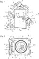
- Fig. 1 shows schematically a first exemplary embodiment of a two-stroke engine 1.
- the two-stroke engine 1 is a single-cylinder engine.
- the two-stroke engine 1 is a two-stroke engine that works with a scavenging template.
- the two-stroke engine 1 has a cylinder 2.
- a cylinder bore 27 is formed in the cylinder 2.
- the cylinder 2 has a cylinder longitudinal axis 24, which is the central axis of the cylinder bore 27.
- a combustion chamber 3 is formed in the cylinder 2.
- the combustion chamber 3 is delimited by a piston 5, which is mounted back and forth in the cylinder 2 in the direction of the cylinder longitudinal axis 24.
- the piston 5 drives a crankshaft 7 which is rotatably mounted in a crankcase interior 9 of a crankcase 4 via a connecting rod 6.
- the crankshaft 7 is rotatably mounted in the crankcase 4 about an axis of rotation 8.
- the crankshaft 7 is used to drive a tool of a work device.
- the two-stroke engine 1 has several overflow channels 10, 11, which fluidly connect the crankcase interior 9 to the combustion chamber 3 in the area of the bottom dead center of the piston 5.
- the overflow channels 10, 11 open with overflow windows 46, 47 on the cylinder bore 27.
- the overflow channels 10, 11 are brought together into a common section 45 and pass into the crankcase interior 9 at a common inlet opening 28.
- the overflow channels 10, 11 have a first section 29 which is delimited by the cylinder 2.
- the first section 29 is closed over its entire circumference and is completely formed in the cylinder 2.
- the section 29 includes a section in which the overflow channels 10 and 11 are guided together, and sections in which the overflow channels 10 and 11 run separately from one another.
- the overflow channels 10, 11 are not open to the cylinder bore 27 on their circumference.
- the overflow channels 10, 11 have a second section 30, which is delimited by the crankcase 4 and is also closed over its entire circumference. In the exemplary embodiment, all overflow channels 10, 11 are guided together in the second section 30. In the exemplary embodiment, the second section 30 forms part of the common section 45, in which the overflow channels 10, 11 are guided together.
- the two-stroke engine 1 has an air filter 23 through which combustion air is sucked in during operation.
- the two-stroke engine 1 has a mixture channel 12 which opens at a mixture inlet 13 on the cylinder bore 27.
- the mixture inlet 13 is controlled by the piston 5 and is opened towards the crankcase interior 9 in the area of the top dead center of the piston 5.
- a section of the mixture channel 12 is formed in a carburetor 16.
- a throttle element 17 and, in the exemplary embodiment, a choke element 18 are provided in the carburettor 16.
- fuel is supplied to the air sucked in via the air filter 23.
- an air duct 14 is additionally provided for supplying rinsing air.
- the air control element 19 to control the supplied air Amount of purge air stored.
- the elements for controlling the flow cross section are designed as pivotally mounted flaps.
- a common throttle element can be provided for the mixture channel 12 and the air channel 14.
- the throttle element is advantageously arranged in a common intake duct, which is advantageously divided into the air duct 14 and the mixture duct 12 downstream of the carburettor 16.
- the air duct 14 opens into two air inlet openings 15 on the cylinder bore 27, of which in Fig. 1 one is shown.
- the second air inlet opening 15 is symmetrical to the cutting plane in Fig. 1 arranged.
- the air inlet openings 15 are also controlled by the piston 5.
- the piston 5 has two piston pockets 20, of which in Fig. 1 one is visible.
- the piston pockets 20 connect the air inlet openings 15 in the area of the top dead center of the piston 5 with the overflow windows 46 and 47. Air from the air duct 14 can be stored upstream in the overflow channels 10 and 11 via the piston pockets 20.
- An outlet opening 21 leads from the combustion chamber 3 and opens into an outlet channel 22.
- the outlet opening 21 is also controlled by the piston 5.
- the mixture in combustion chamber 3 is created by the piston moving upwards 5 compressed and ignited in the area of the top dead center of the piston 5 by a spark plug, not shown.
- the piston 5 is accelerated towards the crankcase 4 due to the combustion that then takes place.
- exhaust gases flow out of the combustion chamber 3 through the outlet opening 21 and the outlet channel 22.
- the overflow windows 46 and 47 are opened by the piston 5, purge air and then fresh mixture flow into the combustion chamber 3 for the next engine cycle.
- the cylinder 2 has a connecting flange 25 for fixing it on the crankcase 4.
- the cylinder 2 rests on the crankcase 4 with a flange plane 26 formed on the connecting flange 25.
- a seal is advantageously arranged between cylinder 2 and crankcase 4.
- the cylinder 2 has an extension 31 which projects beyond the flange plane 26 into the crankcase 4. Part of the section 29 of the overflow channels 10, 11 is guided in the extension 31. As a result, the section of the overflow channels 10 and 11 formed in the cylinder 2 is extended.
- the two-stroke engine 1 is advantageously the drive motor in a hand-held implement.
- a chainsaw 32 is shown as an exemplary embodiment of a hand-held implement.
- the chainsaw 32 has a guide rail 33 on which a saw chain 34 is arranged all around.
- the saw chain 34 is the tool of the chainsaw 32.
- the saw chain 34 is driven by the two-stroke engine 1.
- the chainsaw 32 has a rear handle 35 and a handlebar 36. Other types of handles can also be provided.
- a hand protection bar 37 runs on the side of the handle bar 36 facing the saw chain 34.
- the hand protection bar 37 can be provided for triggering a chain brake, not shown, of the saw chain 34.
- the chainsaw 32 has an exhaust silencer 41, which is connected to the outlet channel 22 ( Fig. 1 ) of the two-stroke engine 1 connects.
- the chainsaw 32 has a motor housing 38 which is vibration-decoupled from the handles 35 and 36 via vibration elements (not shown).
- the motor housing 38 includes an oil tank 39 and a fuel tank 40.
- On the motor housing 38 the two-stroke engine 1 is arranged.
- the crankcase 4 is advantageously at least partially formed in one piece with parts of the engine housing 38.
- the oil tank 39 is used to lubricate the saw chain 34.
- the oil tank 39 is arranged adjacent to the exhaust silencer 41 and the crankcase 4 of the two-stroke engine 1.
- the fuel tank 40 is arranged adjacent to the rear handle 35.
- Fig. 3 shows an exemplary embodiment of the cylinder 2 in detail.
- the same reference numbers designate corresponding components in all exemplary embodiments.
- the cylinder 2 is in the exemplary embodiment Fig. 3 designed in one piece.
- the cylinder 2 has a base body 54 on which the overflow channels 10, 11 ( Fig. 1 ), the extension 31 and a collar 42 are formed. Cooling fins 55 are also formed on the cylinder 2.
- the extension 31 and the collar 42 protrude beyond the flange plane 26 to the crankcase 4.
- a section of the cylinder bore 27 is formed in the collar 42, as shown Fig. 6 shows. How Fig. 3 shows, the extension 31 and the collar 42 are at a distance b from one another.
- the extension 31 and the collar 42 are therefore designed separately from one another and protrude from the connecting flange 25 in different areas.
- the extension 31 has a length a.
- the length a is measured from the flange plane 26 to an end face 68 of the extension 31.
- the overflow channels 10, 11 open at the end face 68.
- the length a is advantageously at least 2.5 mm, in particular at least 5 mm, preferably at least 10 mm.
- the length a is preferably a maximum of 15 mm.
- the length a is measured parallel to the longitudinal axis 24 of the cylinder.
- the collar 42 has a length c.
- the length c is also measured parallel to the longitudinal axis 24 of the cylinder.
- the length c is greater than the length a.
- it can also be provided that the length a is greater than the length c or that the lengths a and c are the same size.
- the crankcase 4 is composed of two partial shells which are divided perpendicular to the axis of rotation 8 of the crankshaft 7.
- the crankcase 4 is formed on the engine housing 38.
- the partial shells of the motor housing 38 form the partial shells of the crankcase 4.
- Fig. 4 shows a partial shell 66 of the motor housing 38.
- Fig. 4 shows a view parallel to the axis of rotation 8 of the crankshaft 7 of a parting plane 50 of the motor housing 38.
- the two partial shells 66 of the motor housing 38 abut one another, in particular with the interposition of a seal. It can be provided that the motor housing 38 is made of metal.
- the motor housing 38 is advantageously formed from two partial shells 66 produced using the die-casting process. It can also be provided that the motor housing 38 is made of plastic.
- the partial shells 66 are advantageously designed as injection molded parts and connected to one another at the parting plane 50. The partial shells 66 can be connected to one another, for example, via a welding process, in particular via an ultrasonic welding process.
- the crankcase 4 has a support surface 56 for the cylinder 2.
- the connecting flange 25 is to be arranged on the support surface 56, in particular with the interposition of a seal.
- a recess 57 for the extension 31 is formed in the support surface 56.
- a filler piece 59 projects beyond the support surface 56 into the cylinder 2.
- the filler piece 59 projects, as Fig. 6 shows, into the interior of the cylinder bore 27.
- a gap 67 is formed between the filler piece 59 and the cylinder bore 27, into which the piston 5 enters at bottom dead center.
- a wall section 58 is formed between the depression 57 and the filler piece 59, which separates the depression 57 from the gap 67.
- the collar 42 projects into the gap 67.
- Fig. 5 shows the engine housing 38 with the cylinder 2 and a schematically illustrated exhaust silencer 41 arranged on the cylinder 2.
- the exhaust silencer 41 is arranged in a silencer space 64, which is delimited by the engine housing 38 and the cylinder 2.
- the extension 31 projects into the depression 57.
- a wall section 65 runs between the second section 30 of the overflow channel 10, 11 and the silencer space 64.
- the wall section 65 delimits both the overflow channel 10, 11 and the silencer space 64.
- On one side of the Wall section 65 is guided by the second section 30 of the overflow channel 10, 11 and the silencer chamber 64 is formed on the other side of the wall section 65.
- An intermediate wall 49 is formed on the motor housing 38, which forms part of the crankcase 4 and delimits the second section 30 of the overflow channel.
- the intermediate wall 49 forms part of the wall of the oil tank 39 and delimits the oil tank 39. This enables a large volume of the oil tank 39.
- the second section 30 of the overflow channel 10, 11 is guided close to the crankcase interior 9. This is also in Fig. 6 shown.
- the second section 30 has an inner wall 51 which faces the crankcase interior 4.
- the second section 30 also has an outer wall 52 which is further away from the crankcase interior 9 than the inner wall 51.
- the second section 30 has a section 53 in which the inner wall 51 runs parallel to the longitudinal axis 24 of the cylinder.
- the outer wall 52 is slightly inclined to the cylinder longitudinal axis 24 in the exemplary embodiment.
- the inclination of the outer wall 52 is selected such that the distance d between the inner wall 51 and the outer wall 52 decreases in the direction of flow towards the combustion chamber 3. In the exemplary embodiment, the distance d decreases over the entire section 53. However, it can be provided that the distance d only decreases over part of the section 53.
- Fig. 6 also shows the course of the air duct 14 up to the air inlet opening 15.
- Fig. 6 also shows the position of the inlet opening 28, via which the overflow channels 10, 11 are connected to the crankcase interior 9.
- the crankcase 4 has a crankcase plane 60.
- the crankcase plane 60 runs perpendicular to the cylinder longitudinal axis 24 and contains the axis of rotation 8 of the crankshaft 7.
- the inlet opening 28 and the cylinder 2 are arranged on opposite sides of the crankcase plane 60 in the exemplary embodiment.
- the inlet opening 28 is therefore arranged on the side of the crankcase plane 60, which is away from the cylinder 2. This will In a simple manner, a large length of the overflow channels 10, 11 and thereby a favorable flow formation is achieved.
- the collar 42 projects beyond the flange plane 26 to the crankcase 4.
- the collar 42 projects into the space 67 between the filler piece 59 and the wall section 58.
- Fig. 7 shows a section through the cylinder 2.
- the overflow window 47 of the overflow channel 11 is arranged closer to the mixture inlet 13 than the overflow window 46 of the overflow channel 10.
- the cylinder also has a pulse channel 48, which is connected to a fuel pump of the carburettor, not shown 16 ( Fig. 1 ) is connected and this via the fluctuating pressure in the crankcase interior 9 ( Fig. 1 ) drives.
- the cylinder 2 has an inlet flange 61, to which the air duct 14 and the mixture duct 12 are guided.
- a connecting piece is advantageously fixed on the inlet flange 61, through which combustion air is sucked in.
- Fig. 8 shows a view of the connecting flange 25 in the direction of the cylinder longitudinal axis 24.
- the collar 42 and the extension 31 are designed separately from one another and are at a distance b from one another.
- the overflow channels 10, 11 on the opposite sides of the cylinder 2 are brought together in the extension 31.
- the cylinder 2 has a central plane 63 which divides the extension 31 in the middle and contains the longitudinal axis 24 of the cylinder.
- Fig. 8 shows a view of the combustion chamber roof 43 in cylinder 2. How Fig. 8 also shows, 25 screw openings 44 are formed in the cylinder flange, to which the cylinder 2 can be screwed to the crankcase 4.
- the section 29 of the overflow channels 10 and 11 in the extension 31 has an outer wall 76 remote from the cylinder longitudinal axis 24, an inner wall 77 opposite the outer wall 76 and two the inner wall 77 and the outer wall 76 connecting side walls 78.
- the side walls 78 delimit the first section 29 of the overflow channels 10 and 11 in the circumferential direction to the cylinder longitudinal axis 24.
- the inner wall 77 delimits the first section 29 in the direction of the cylinder bore 27.
- the outer wall 76 delimits the first section 29 to the side facing away from the cylinder bore 27.
- the extension 31 has an elongated, approximately rectangular cross section.
- the parting plane 50 of the motor housing 38 which is in Fig. 4 forms the drawing plane, can coincide with the middle plane 63. Alternatively, it can also be provided that the parting plane 50 runs at a distance from the central plane 63.
- the parting plane 50 is advantageously arranged parallel to the central plane 63.
- the parting plane 50 which is in Fig. 8 coincides with the central plane 63, divides the extension 31, so that a part of the second section 30 of the overflow channels 10 and 11 is formed in each partial shell 66 of the crankcase 4.
- Fig. 9 shows a side view of the cylinder 2, namely the inlet flange 61.
- Fig. 10 shows a section through the cylinder 2 in the area of the extension 31, the course of the overflow channels 10 and 11 in the cylinder 2 being partially shown with a dashed line. As the 9 and 10 show, the overflow channels 10 and 11 are limited by the one-piece base body 54 of the cylinder 2. Elements separate from the cylinder 2 that close the overflow channels 10 and 11 to the outside of the cylinder 2, such as covers or the like, are not provided.
- the extension 31 is shown in section.
- the extension 31 has a width f measured perpendicular to the central plane 63.
- the width f is smallest at the end face 68.
- the width f of the overflow channels 10 and 11 in the extension 31 increases.
- the side walls 78 of the first section form 29 in the extension 31 Undercuts in the direction of the end face 68 of the extension 31.
- the section of the overflow channels 10 and 11 formed in the extension 31 cannot therefore be molded in a die-casting process with a drawn core.
- the side walls 78 in the exemplary embodiment are curved in the extension 31.
- the side walls 78 are in the direction from the end face 68 to the combustion chamber roof 43 ( 7 and 8 ) curved away from each other.
- the side walls 78 are convexly curved.
- the course of the overflow channels 10 and 11 is also in the Figures 11 and 12 shown.
- the position of the end face 68 and the flange plane 26 is in the Figures 11 and 12 shown schematically with dash-dotted lines.
- Fig. 11 the curvature of the side walls 78 is visible in the area between the end face 68 and the flange plane 26.
- cylinder 2 namely from the flange level 26 to the overflow windows 46 ( Fig. 14 ) and 47, the side walls 78 are curved.
- Fig. 12 shows, the outer wall 76 of the overflow channels 10 and 11, which is remote from the cylinder longitudinal axis 24, runs inclined to the cylinder longitudinal axis 24 in the area between the end face 68 and the flange plane 26.
- the outer wall 76 is inclined in the direction from the end face 68 to the flange plane 26 to the cylinder longitudinal axis 24.
- the outer wall 76 therefore has a smaller distance Cylinder longitudinal axis 24 than on the end face 68. This is also in Fig. 7 shown.
- the outer wall 76 therefore does not form an undercut in the direction of the end face 68.
- the inner wall 77 of the overflow channels 10 and 11, which is closer to the cylinder longitudinal axis 24, is inclined towards the combustion chamber roof 43, i.e. in the direction from the end face 68 to the flange plane 26, towards the cylinder longitudinal axis 24, as Fig. 7 shows. Due to its inclination, the inner wall 77 forms an undercut in a direction that is directed away from the combustion chamber roof 43 parallel to the cylinder longitudinal axis 24.
- the inner wall 77 has a smaller distance from the cylinder longitudinal axis 24 in the flange plane 26 than on the end face 68.
- the Figures 13 and 14 show an exemplary embodiment of a multi-part cylinder 2.
- the same reference numbers designate corresponding elements in all figures.
- the course of the overflow channels 10 and 11 corresponds to that of the previous exemplary embodiment.
- the cylinder 2 has a base body 54 into which an insert part 70 is inserted.
- the insertion part 70 forms the extension 31.
- part of the extension 31 is formed by the insertion part 70 and another part of the extension 31 is formed by the base body 54 of the cylinder 2.
- the insertion part 70 is arranged in a receptacle 69 of the base body 54.
- the receptacle 69 is designed as a recess in the flange plane 26.
- the insertion part 70 has a shoulder 83, which rests on the flange plane 26 and thereby limits the insertion depth of the insertion part 70.
- Fig. 14 shows the insert part 70 in the recording 69.
- the insertion part 70 has a widened area 81, which can be arranged flush with the flange plane 26.
- the widened area 81 advantageously does not protrude from the receptacle 69 beyond the flange plane 26.
- 15 and 16 show the base body 54 of the cylinder 2 in the area of the receptacle 69 without the insert part 70 arranged in the receptacle 69.
- the Figures 17 to 20 show the design of the insert part 70 in detail.
- the insertion part 70 has a section 84 which is to be arranged in the receptacle 69.
- the insertion part 70 also has the extension 31.
- Section 84 includes the widened area 81.
- the side walls 78 in the widened area 81 are convexly curved in the direction of flow.
- the widened area 81 enables comparatively large bending radii of the side walls 78 in this area.
- the insertion part 70 has a projection 79 on the side remote from the extension 31.
- a flow divider 80 is formed on the projection 79, as well Fig. 19 shows.
- the flow divider 80 divides overflow channels 10 and 11, whose overflow windows 46, 47 are arranged on one side of the central plane 63, from the overflow channels 10 and 11, whose overflow windows 46 and 47 are arranged on the other side of the central plane 63.
- the insertion part 70 is composed of two parts 71 and 72, which are joined together at a parting plane 73.
- the parting plane 73 is curved.
- the curvature of the parting plane 73 advantageously follows the curvature of the inner wall 77 and/or the curvature of the outer wall 76 of the transfer channels 10 and 11.
- the part 71 has positioning projections 75 which protrude into receptacles 82 of the other part 72.
- a recording 82 is shown as an example.
- Fig. 19 shows the curvature of the side walls 78 relative to one another.
- the side walls 78 are curved away from each other, so that the distance f between the side walls 78 increases as the distance from the end face 68 increases.
- Fig. 20 shows the curvature of the outer wall 76 and the inner wall 77.
- the outer wall 76 and the inner wall 77 are advantageously curved in the same direction, so that the distance between the outer wall 76 and the inner wall 77 in the extension 31 is approximately constant.
- the Figures 21 and 22 show the widened area 81 and the course of the overflow channels 10 and 11 in the insertion part 70. How Fig. 22 shows, the side walls 78 extend into the widened area 81.
- the design of the overflow channels 10 and 11 in the exemplary embodiment Fig. 13 to 20 Advantageously corresponds to the design of the overflow channels 10 and 11 of the previous exemplary embodiment, so that reference is made to the description of the other exemplary embodiment with regard to further features.
- the cylinder 2 can also be placed on a differently designed crankcase 4 to form a two-stroke engine 1.
- the cylinder 2 is placed on a crankcase 4, in which a second section 30 of the overflow channel 10, 11 is formed. It can also be provided to place the cylinder 2 on a crankcase 4 in which no section of overflow channels 10, 11 is formed.
- the cylinder 2 is advantageously manufactured in all exemplary embodiments using gravity casting.
- die-cast production can also be provided.
- the alternative embodiment of the two-stroke engine 1 includes a cylinder 2 and a crankcase 4.
- the crankcase 4 is composed of an upper partial shell 90 and a lower partial shell 91.
- the partial shells 90 and 91 are connected to one another at a dividing plane 92, which contains the axis of rotation 8 of the crankshaft 7.
- the two-stroke engine 1 comprises two overflow channels 10, which are guided in a common section 45.
- the common section 45 is limited in the cylinder 2 by an elevation 93 of the upper partial shell 90 of the crankcase 4.
- the elevation 93 delimits the common section 45 both in the direction of the cylinder longitudinal axis 24 and in the circumferential direction of the cylinder longitudinal axis 24.
- the cylinder 2 delimits the common section 45 radially outwards with respect to the cylinder longitudinal axis 24.
- the upper sub-shell 90 of the crankcase 4 has an extension 94 which projects beyond the dividing plane 92 into the lower sub-shell 91.
- the extension 94 delimits the second section 30 of the overflow channels 10 over its entire circumference.
- the extension 94 forms an outer wall 76, an inner wall 77 and two side walls 78 which delimit the overflow channels 10.
- the extension 94 points, as in particular Fig. 24 shows an approximately rectangular cross section.
- Fig. 23 shows a section through the central plane 63 of the cylinder 2.
- the overflow channel 10 in the extension 94 has a significantly larger extent than parallel to the central plane 63, as shown Fig. 24 and 25 show.
- the common section 45 of the overflow channels 10 is the only section of an overflow channel that is guided over the flange plane 26.
Landscapes
- Engineering & Computer Science (AREA)
- Chemical & Material Sciences (AREA)
- Combustion & Propulsion (AREA)
- Mechanical Engineering (AREA)
- General Engineering & Computer Science (AREA)
- Cylinder Crankcases Of Internal Combustion Engines (AREA)
Abstract
Description
- Die Erfindung betrifft einen Zylinder der im Oberbegriff des Anspruchs 1 angegebenen Gattung, einen Zweitaktmotor mit einem Zylinder sowie ein Arbeitsgerät mit einem Zweitaktmotor.
- Aus der
DE 10 2009 059 144 A1 ist ein Zweitaktmotor bekannt, bei dem alle Überströmkanäle unter dem Auslass aus dem Brennraum zusammengeführt sind und gemeinsam in den Kurbelgehäuseinnenraum übertreten. Um eine Herstellung des Zylinders im Druckgussverfahren zu ermöglichen, ist vorgesehen, die Überströmkanäle zum Zylinderinnenraum hin über eine Laufbuchse zu begrenzen oder die Überströmkanäle nach außen mit Deckeln zu verschließen und von der Kurbelgehäuseseite aus ein Einschubteil in den Zylinder einzusetzen, das die Überströmkanäle begrenzt. - Aus der
DE 10 2010 045 332 A1 ist ein Zylinder eines Zweitaktmotors bekannt, der einen in den Bereich des Kurbelgehäuses ragenden Stutzen aufweist. In dem Stutzen sind Überströmkanäle von beiden Seiten des Zylinders ins Kurbelgehäuse geführt. Die Überströmkanäle sind von Deckeln verschlossen. - Der Erfindung liegt die Aufgabe zugrunde, einen Zylinder für einen Zweitaktmotor der gattungsgemäßen Art zu schaffen, der einen vorteilhaften Aufbau besitzt. Eine weitere Aufgabe der Erfindung besteht darin, einen Zweitaktmotor zu schaffen, der einen vorteilhaften Aufbau besitzt. Eine weitere Aufgabe der Erfindung besteht darin, ein Arbeitsgerät mit einem Zweitaktmotor mit vorteilhaftem Aufbau anzugeben.
- Diese Aufgabe wird bezüglich des Zylinders durch einen Zylinder mit den Merkmalen des Anspruchs 1 gelöst. Bezüglich des Zweitaktmotors wird die Aufgabe durch einen Zweitaktmotor mit den Merkmalen des Anspruchs 6 gelöst. Bezüglich des Arbeitsgeräts wird die Aufgabe durch ein Arbeitsgerät mit den Merkmalen des Anspruchs 17 gelöst.
- Mit Zweitaktmotoren, bei denen alle Überströmkanäle unter dem Auslass zusammengeführt sind, lassen sich günstige Abgaswerte erreichen. Bei einer solchen Gestaltung der Überströmkanäle sind die Kanäle, die zu den einlassnahen Überströmfenstern führen, länger als die Überströmkanäle, die zu den auslassnahen Überströmkanälen führen. Um dennoch einen ausreichend großen Anteil von Luft und Gemisch über die einlassnahen Überströmkanäle in den Brennraum zuzuführen, hat sich gezeigt, dass eine gleichmäßige Umlenkung der Überströmkanäle mit möglichst großen Umlenkradien an den Überströmkanälen wünschenswert sind. Hierfür ist es vorteilhaft, wenn die Umlenkung der Strömung in die Umfangsrichtung bereits im Kurbelgehäuse möglichst weit entfernt von den Überströmfenstern beginnt.
- Für einen Zylinder ist vorgesehen, dass der erste Abschnitt des Überströmkanals zumindest teilweise an einem über die Flanschebene ragenden Fortsatz ausgebildet ist und dass mindestens eine Seitenwand in dem Fortsatz konvex gewölbt verläuft.
- Dadurch, dass die Seitenwand in dem Fortsatz konvex gewölbt verläuft, beginnt die Umlenkung der Überströmkanäle auf die beiden Seiten des Zylinders bereits unterhalb der Flanschebene. Dadurch wird eine allmähliche, langsame Umlenkung des ersten Abschnitts des Überströmkanals erreicht. Dadurch können Strömungsablösungen in dem Überströmkanal vermieden werden und es wird eine gute Füllung der Überströmkanäle und ein vorteilhaftes Einströmverhalten in den Brennraum erreicht.
- Vorteilhaft weist der erste Abschnitt des Überströmkanals mindestens eine den ersten Abschnitt zur Zylinderbohrung begrenzende Innenwand auf. Die Innenwand ist vorteilhaft in Richtung zum Brennraumdach zur Zylinderlängsachse hin geneigt. Der Überströmkanal mündet vorteilhaft mit mindestens einem Überströmfenster in den Brennraum. Durch die Neigung der Innenwand wird die Strömung in dem mindestens einen Überströmkanal bereits im Fortsatz in Richtung auf den Brennraum, insbesondere zu dem mindestens einen Überströmfenster hin gelenkt.
- Im Kurbelgehäuse können die Überströmkanäle durch in Längsrichtung der Überströmkanäle zum Zylinderanschlussflansch hin gezogene Kerne oder - bei einer Entformung in Richtung der Drehachse der Kurbelwelle - parallel zur Drehachse der Kurbelwelle entformt werden. Dies ist dann möglich, wenn das Kurbelgehäuse senkrecht zur Drehachse der Kurbelwelle geteilt ist. Im Bereich der Trennung der Kurbelgehäusehalbschalen bzw. in dem Bereich, in dem ein Schieber der Spritzgussform endet, können schmale Grate oder Unregelmäßigkeiten an der Wand des Überströmkanals entstehen, die nur aufwändig entfernt werden können. Es hat sich gezeigt, dass bereits geringe Wandunebenheiten zu einer unerwünschten Strömungsablösung im Überströmkanal führen können.
- Um Unebenheiten an den Wänden der Überströmkanäle weitgehend zu vermeiden oder mit möglichst großem Abstand zu den Überströmfenstern anzuordnen, ist erfindungsgemäß vorgesehen, dass der erste, im Zylinder ausgebildete Abschnitt des Überströmkanals zumindest teilweise an einem über die Flanschebene ragenden Fortsatz des Zylinders ausgebildet ist. Dadurch wird der im Zylinder ausgebildete Abschnitt des Überströmkanals über die Flanschebene hinaus verlängert. In dem Fortsatz ist der Überströmkanal dabei über seinen gesamten Umfang vom Zylinder begrenzt. Dadurch wird eine günstige Strömungsführung sichergestellt. Insbesondere bei einem im Druckguss hergestellten Zylinder ist eine weitgehend freie Formgebung der Überströmkanäle so über eine sehr große Länge der Überströmkanäle auf einfache Weise möglich.
- Der Fortsatz ist vorteilhaft einteilig mit einem Grundkörper des Zylinders ausgebildet. Bevorzugt ist der Zylinder einteilig ausgebildet und weist keine Laufbuchse, keine Einschubteile zum Verschließen der Überströmkanäle zur Zylinderinnenseite und keine Deckel zum Verschließen der Überströmkanäle zur Zylinderaußenseite auf. Dadurch wird ein einfacher Aufbau erreicht und die Überströmkanäle sind über ihren gesamten Umfang im Grundkörper des Zylinders ausgebildet, so dass Wandunebenheiten am Überströmkanal vermieden sind. Ein einteilig ausgebildeter Zylinder ist bevorzugt im Schwerkraftguss hergestellt. Im Schwerkraftguss können Hinterschnitte gut hergestellt werden.
- Der Fortsatz verschiebt den Bereich, an dem die beiden Abschnitte des Überströmkanals aneinanderstoßen, in Richtung der Eintrittsöffnung in den Kurbelgehäuseinnenraum. Dadurch wird der im Zylinder ausgebildete Abschnitt des Überströmkanals verlängert und so eine günstige Strömungsausbildung im Zylinder begünstigt. Insbesondere bei Herstellung des Zylinders im Druckgussverfahren können die Überströmkanäle im Zylinder mit großen Umlenkradien ausgebildet werden, wodurch sich Strömungsablösungen an den Wänden der Überströmkanäle weitgehend vermeiden lassen. Dies ist insbesondere vorteilhaft für einen Zylinder, der einlassnahe und auslassnahe Überströmkanäle aufweist. Dadurch kann der über die einlassnahen Überströmkanäle zuzuführende Anteil an Luft und Frischgemisch in gewünschter Weise eingestellt werden.
- In alternativer Ausführung ist vorgesehen, dass der Fortsatz zumindest teilweise an einem Einschubteil ausgebildet ist. Dadurch kann eine gewünschte Strömungsführung auf einfache Weise hergestellt werden. Vorteilhaft ist das Einschubteil zur Anordnung in einer Aufnahme des Zylinders vorgesehen. Das Einschubteil ragt insbesondere in eine Aufnahme des Kurbelgehäuses. Es kann jedoch auch vorgesehen sein, dass das Einschubteil vollständig in einer Aufnahme des Kurbelgehäuses anzuordnen ist. In besonders vorteilhafter Gestaltung ist das Einschubteil mehrteilig, insbesondere zweiteilig ausgebildet. Dadurch kann das Einschubteil in einem Spritzgussverfahren, insbesondere ohne Verwendung von Kernen, hergestellt werden. Der Zylinder kann im Schwerkraftguss oder im Druckguss hergestellt sein.
- In vorteilhafter Ausführung weist der Fortsatz einen im Wesentlichen rechteckigen Querschnitt auf. Die Erstreckung des Querschnitts senkrecht zu einer Mittelebene des Zylinders ist vorteilhaft größer als die Erstreckung des Querschnitts parallel zur Mittelebene des Zylinders. Auch ein anderer Querschnitt des Fortsatzes kann vorteilhaft sein.
- Für einen Zweitaktmotor ist vorteilhaft vorgesehen, dass der Zylinder einen ersten, umfangsseitig geschlossenen Abschnitt mindestens eines Überströmkanals aufweist, und dass das Kurbelgehäuse mindestens einen umfangsseitig geschlossenen zweiten Abschnitt des mindestens einen Überströmkanals aufweist.
- Dadurch, dass der erste Abschnitt zumindest teilweise in dem Fortsatz ausgebildet ist, wird der im Zylinder ausgebildete Abschnitt des Überströmkanals verlängert.
- Das Kurbelgehäuse ist vorteilhaft im Druckgussverfahren oder als Spritzgussteil ausgebildet und ist so einfach und kostengünstig herstellbar.
- Vorteilhaft weist das Kurbelgehäuse eine Auflagefläche für den Zylinder auf. An der Auflagefläche schließt der Zylinder an das Kurbelgehäuse an, vorteilhaft unter Zwischenlage einer Dichtung. Die Auflagefläche ist vorteilhaft eine ebene Fläche. Es ist vorgesehen, dass die Auflagefläche eine Vertiefung für den Fortsatz aufweist. Es kann vorgesehen sein, dass der Fortsatz und die Vertiefung zusammenwirken, um die Position des Zylinders gegenüber dem Kurbelgehäuse festzulegen. Der Fortsatz weist demnach eine Zentrierfunktion auf. Der Fortsatz legt die Position des Zylinders gegenüber dem Kurbelgehäuse vorteilhaft spielfrei fest. Es kann auch vorgesehen sein, dass der Fortsatz mit Spiel in die Vertiefung ragt.
- Bevorzugt weist der Zweitaktmotor mehrere Überströmkanäle auf, die an einer gemeinsamen Eintrittsöffnung in den Kurbelgehäuseinnenraum übertreten. Vorteilhaft verlaufen mindestens zwei Überströmkanäle, insbesondere alle Überströmkanäle des Zweitaktmotors durch den Fortsatz. Dadurch wird eine günstige Strömungsführung der Überströmkanäle erreicht und es ergibt sich ein einfacher Aufbau des Kurbelgehäuses. Alternativ kann vorgesehen sein, dass zwei oder mehrere Fortsätze vorgesehen sind, durch die jeweils ein oder mehrere Überströmkanäle geführt sind.
- Das Kurbelgehäuse weist eine Kurbelgehäuseebene auf, die die Drehachse der Kurbelwelle enthält und die senkrecht zur Zylinderlängsachse verläuft. Vorteilhaft ist vorgesehen, dass die Eintrittsöffnung und der Zylinder auf gegenüberliegenden Seiten der Kurbelgehäuseebene angeordnet sind. Die Eintrittsöffnung ist demnach in einem dem Zylinder entfernt liegenden Bereich des Kurbelgehäuses angeordnet. Dadurch ergibt sich eine große Länge der Überströmkanäle. Es hat sich gezeigt, dass sich hierdurch vorteilhafte Strömungsverhältnisse in den Überströmkanälen und geringe Abgasemissionswerte erzielen lassen.
- Der Zweitaktmotor weist vorteilhaft eine Mittelebene auf, die senkrecht zur Drehachse der Kurbelwelle verläuft und die die Zylinderlängsachse enthält. Vorteilhaft ist das Kurbelgehäuse durch zumindest zwei Teilschalen begrenzt, die an einer Trennebene miteinander verbunden sind. Die Trennebene der Teilschalen verläuft vorteilhaft zumindest in dem das Kurbelgehäuse begrenzenden Abschnitt der Teilschalen parallel zur Mittelebene. Es kann vorgesehen sein, dass die Trennebene mit der Mittelebene des Zweitaktmotors zusammenfällt. Es kann jedoch auch vorgesehen sein, dass die Trennebene der Teilschalen einen Abstand zur Mittelebene aufweist.
- Insbesondere bei Zweitaktmotoren, die in handgeführten Arbeitsgeräten eingesetzt sind, ist ein geringer Bauraum wünschenswert, so dass sich eine kleine Baugröße des Arbeitsgeräts ergibt. Hierfür ist vorteilhaft vorgesehen, dass der zweite Abschnitt des Überströmkanals nahe am Kurbelgehäuseinnenraum geführt ist. Vorteilhaft weist der zweite Abschnitt des Überströmkanals einen Teilabschnitt auf, in dem zumindest eine Wand des Überströmkanals parallel zur Zylinderlängsachse verläuft. Die parallel zur Zylinderlängsachse verlaufende Wand ist insbesondere die dem Kurbelgehäuseinnenraum benachbart liegende Innenwand des Überströmkanals. Dadurch wird ein kompakter Aufbau erreicht. Aufgrund des über die Flanschebene in das Kurbelgehäuse ragenden Fortsatzes ist dennoch eine günstige Strömungsführung des Überströmkanals möglich. Bevorzugt verringert sich der Abstand zwischen der Innenwand und der Außenwand des Überströmkanals in diesem Teilabschnitt in Strömungsrichtung zum Brennraum.
- Vorteilhaft weist der Zylinder einen Kragen auf, der über die Flanschebene in das Kurbelgehäuse ragt und an dessen Innenseite die Zylinderbohrung verläuft. Bevorzugt weist der Kragen an jeder Stelle einen Abstand zu dem Fortsatz auf. Der Kragen und der Fortsatz sind demnach getrennt voneinander ausgebildet. Es kann vorgesehen sein, dass der Kragen und der Fortsatz gemeinsam die Position des Zylinders gegenüber dem Kurbelgehäuse festlegen, insbesondere spielfrei.
- Für ein Arbeitsgerät mit einem Zweitaktmotor ist vorgesehen, dass an den Auslasskanal ein Abgasschalldämpfer anschließt, der in einem Schalldämpferraum angeordnet ist. Das Kurbelgehäuse weist einen Wandabschnitt auf, der den zweiten Abschnitt des Überströmkanals und den Schalldämpferraum begrenzt. Der Schalldämpferraum ist demnach unmittelbar an der Außenseite des Kurbelgehäuses angeordnet. Zwischen dem Abgasschalldämpfer und dem Wandabschnitt ist vorteilhaft ein Abstand gebildet, um einen übermäßigen Wärmeeintrag vom Abgasschalldämpfer in das Kurbelgehäuse zu vermeiden. Insbesondere, wenn der Überströmkanal im Kurbelgehäuse mit geringem Abstand zum Kurbelgehäuseinnenraum verläuft, kann ausreichend Bauraum für den Abgasschalldämpfer zur Verfügung gestellt werden, so dass sich insgesamt eine geringe Baugröße des Arbeitsgeräts ergibt.
- Das Arbeitsgerät weist vorteilhaft ein Motorgehäuse und einen Öltank zur Versorgung eines Werkzeugs des Arbeitsgeräts mit Schmiermittel auf. Der Öltank und das Kurbelgehäuse sind vorteilhaft in dem Motorgehäuse ausgebildet. Das Motorgehäuse weist vorteilhaft eine Zwischenwand auf, die den zweiten Abschnitt des Überströmkanals und den Öltank begrenzt. Ist der Überströmkanal im Kurbelgehäuse nah am Kurbelgehäuseinnenraum geführt, so kann ein ausreichend großer Bauraum für den Öltank des Arbeitsgeräts sichergestellt werden. Das Arbeitsgerät ist insbesondere eine Motorsäge und das Werkzeug eine Sägekette. Es kann jedoch auch vorgesehen sein, dass das Arbeitsgerät ein anderes handgeführtes Arbeitsgerät ist. Das Arbeitsgerät kann insbesondere ein Trennschleifer, ein Freischneider, ein Blasgerät oder ein Rasenmäher sein.
- Ausführungsbeispiele der Erfindung werden im Folgenden anhand der Zeichnung erläutert. Es zeigen:
- Fig. 1
- eine schematische Darstellung eines Ausführungsbeispiels eines Zweitaktmotors,
- Fig. 2
- eine schematische Darstellung einer Motorsäge,
- Fig. 3
- eine ausschnittsweise Darstellung des Zylinders eines weiteren Ausführungsbeispiels eines Zweitaktmotors,
- Fig. 4
- eine ausschnittsweise Seitenansicht einer Teilschale eines Kurbelgehäuses des Zweitaktmotors,
- Fig. 5
- der Zylinder aus
Fig. 3 und die Teilschale des Kurbelgehäuses ausFig. 4 in ausschnittsweiser, schematischer Seitenansicht, - Fig. 6
- eine schematische Schnittdarstellung durch Zylinder und Kurbelgehäuse aus den
Fig. 3 bis 5 , - Fig. 7
- eine Schnittdarstellung des Zylinders aus
Fig. 6 , - Fig. 8
- eine Ansicht des Zylinders aus
Fig. 7 in Richtung des Pfeils VIII inFig. 7 , - Fig 9
- eine Ansicht des Zylinders aus
Fig. 7 in Richtung des Pfeils IX inFig. 7 , - Fig. 10
- einen Schnitt durch den Zylinder aus
Fig. 7 entlang der Linie X-X inFig. 7 , wobei der nicht sichtbare Verlauf der Überströmkanäle mit gestrichelter Linie dargestellt ist, - Fig. 11
- eine Seitenansicht eines Abgusses der Überströmkanäle,
- Fig. 12
- eine Seitenansicht in Richtung des Pfeils XII in
Fig. 11 , - Fig. 13
- eine Schnittdarstellung eines Ausführungsbeispiels eines Zylinders,
- Fig. 14
- eine ausschnittsweise Ansicht auf den Zylinder in Richtung des Pfeils XIV in
Fig. 13 , - Fig. 15
- eine ausschnittsweise Schnittdarstellung durch den Zylinder vor der Montage eines Einschubteils,
- Fig. 16
- eine Ansicht auf den Zylinder in Richtung des Pfeils XVI in
Fig. 15 , - Fig. 17
- eine perspektivische Darstellung des Einschubteils aus
Fig. 14 und15 , - Fig. 18
- eine Explosionsdarstellung des Einschubteils aus
Fig. 17 , - Fig. 19
- einen Schnitt durch das Einschubteil entlang der Linie XIX-XIX in
Fig. 15 , - Fig. 20
- einen Schnitt durch das Einschubteil entlang der Linie XX-XX in
Fig. 19 , - Fig. 21
- eine Ansicht des Einschubteils in Richtung des Pfeils XXI in
Fig. 20 , - Fig. 22
- eine Ansicht des Einschubteils in Richtung des Pfeils XXII in
Fig. 20 , - Fig. 23
- eine perspektivische Schnittdarstellung von Zylinder und Kurbelgehäuse eines Zweitaktmotors,
- Fig. 24 und 25
- perspektivische Darstellungen einer oberen Teilschale des Kurbelgehäuses des Zweitaktmotors aus
Fig. 23 . -
Fig. 1 zeigt schematisch ein erstes Ausführungsbeispiel eines Zweitaktmotors 1. Der Zweitaktmotor 1 ist ein Einzylindermotor. Der Zweitaktmotor 1 ist im Ausführungsbeispiel ein mit Spülvorlage arbeitender Zweitaktmotor. Der Zweitaktmotor 1 weist einen Zylinder 2 auf. Im Zylinder 2 ist eine Zylinderbohrung 27 ausgebildet. Der Zylinder 2 weist eine Zylinderlängsachse 24 auf, die die Mittelachse der Zylinderbohrung 27 ist. Im Zylinder 2 ist ein Brennraum 3 ausgebildet. Der Brennraum 3 ist von einem Kolben 5 begrenzt, der in Richtung der Zylinderlängsachse 24 im Zylinder 2 hin- und hergehend gelagert ist. Der Kolben 5 treibt über ein Pleuel 6 eine in einem Kurbelgehäuseinnenraum 9 eines Kurbelgehäuses 4 drehbar gelagerte Kurbelwelle 7 an. Die Kurbelwelle 7 ist im Kurbelgehäuse 4 um eine Drehachse 8 drehbar gelagert. Die Kurbelwelle 7 dient zum Antrieb eines Werkzeugs eines Arbeitsgeräts. - Der Zweitaktmotor 1 weist mehrere Überströmkanäle 10, 11 auf, die den Kurbelgehäuseinnenraum 9 im Bereich des unteren Totpunkts des Kolbens 5 fluidisch mit dem Brennraum 3 verbinden. In
Fig. 1 ist der Kolben 5 in seinem unteren Totpunkt dargestellt. Die Überströmkanäle 10, 11 münden mit Überströmfenstern 46, 47 an der Zylinderbohrung 27. Im Ausführungsbeispiel sind die Überströmkanäle 10, 11 in einen gemeinsamen Abschnitt 45 zusammengeführt und treten an einer gemeinsamen Eintrittsöffnung 28 in den Kurbelgehäuseinnenraum 9 über. Die Überströmkanäle 10, 11 weisen einen ersten Abschnitt 29 auf, der vom Zylinder 2 begrenzt ist. Der erste Abschnitt 29 ist über seinen gesamten Umfang geschlossen und vollständig im Zylinder 2 ausgebildet. Der Abschnitt 29 umfasst einen Teilabschnitt, in dem die Überströmkanäle 10 und 11 gemeinsam geführt sind, und Teilabschnitte, in denen die Überströmkanäle 10 und 11 separat voneinander verlaufen. Im Abschnitt 29 sind die Überströmkanäle 10, 11 an ihrem Umfang nicht zur Zylinderbohrung 27 hin offen. Die Überströmkanäle 10, 11 weisen einen zweiten Abschnitt 30 auf, der vom Kurbelgehäuse 4 begrenzt und ebenfalls über seinen gesamten Umfang geschlossen ist. Im Ausführungsbeispiel sind alle Überströmkanäle 10, 11 in dem zweiten Abschnitt 30 gemeinsam geführt. Der zweite Abschnitt 30 bildet im Ausführungsbeispiel einen Teil des gemeinsamen Abschnitts 45, in dem die Überströmkanäle 10, 11 gemeinsam geführt sind. - Der Zweitaktmotor 1 weist einen Luftfilter 23 auf, über den im Betrieb Verbrennungsluft angesaugt wird. Der Zweitaktmotor 1 weist einen Gemischkanal 12 auf, der an einem Gemischeinlass 13 an der Zylinderbohrung 27 mündet. Der Gemischeinlass 13 ist im Ausführungsbeispiel vom Kolben 5 gesteuert und im Bereich des oberen Totpunkts des Kolbens 5 zum Kurbelgehäuseinnenraum 9 hin geöffnet. Ein Abschnitt des Gemischkanals 12 ist in einem Vergaser 16 ausgebildet. Im Vergaser 16 sind ein Drosselelement 17 und im Ausführungsbeispiel ergänzend ein Chokeelement 18 vorgesehen. Im Vergaser 16 wird der über den Luftfilter 23 angesaugten Luft Kraftstoff zugeführt. Im Ausführungsbeispiel ist zusätzlich ein Luftkanal 14 zur Zufuhr von Spülvorlagenluft vorgesehen. Im Luftkanal 14 ist ein Luftsteuerelement 19 zur Steuerung der zugeführten Menge von Spülvorlagenluft gelagert. Im Ausführungsbeispiel sind die Elemente zur Steuerung des Strömungsquerschnitts als schwenkbar gelagerte Klappen ausgebildet.
- In alternativer Gestaltung kann ein gemeinsames Drosselelement für den Gemischkanal 12 und den Luftkanal 14 vorgesehen sein. Bei dieser Ausführung ist das Drosselelement vorteilhaft in einem gemeinsamen Ansaugkanal angeordnet, der stromab des Vergasers 16 vorteilhaft in den Luftkanal 14 und dem Gemischkanal 12 geteilt ist.
- Der Luftkanal 14 mündet mit zwei Lufteinlassöffnungen 15 an der Zylinderbohrung 27, von denen in
Fig. 1 eine gezeigt ist. Die zweite Lufteinlassöffnung 15 ist symmetrisch zur Schnittebene inFig. 1 angeordnet. Auch die Lufteinlassöffnungen 15 sind vom Kolben 5 gesteuert. Der Kolben 5 weist zwei Kolbentaschen 20 auf, von denen inFig. 1 eine sichtbar ist. Die Kolbentaschen 20 verbinden die Lufteinlassöffnungen 15 im Bereich des oberen Totpunkts des Kolbens 5 mit den Überströmfenstern 46 und 47. Über die Kolbentaschen 20 kann in den Überströmkanälen 10 und 11 Luft aus dem Luftkanal 14 vorgelagert werden. - Aus dem Brennraum 3 führt eine Auslassöffnung 21, die in einen Auslasskanal 22 mündet. Auch die Auslassöffnung 21 ist vom Kolben 5 gesteuert.
- Im Betrieb wird beim Aufwärtshub des Kolbens 5 nach dem Öffnen des Gemischeinlasses 13 Gemisch in den Kurbelgehäuseinnenraum 9 angesaugt. Im Bereich des oberen Totpunkts des Kolbens 5 wird über die Lufteinlassöffnungen 15 und die Kolbentaschen 20 Luft in den Überströmkanälen 10 und 11 vorgelagert. Beim Abwärtshub des Kolbens 5 wird das Gemisch im Kurbelgehäuseinnenraum 9 verdichtet. Sobald die Überströmfenster 46 und 47 vom Kolben 5 in den Brennraum 3 geöffnet werden, strömt aus den Überströmkanälen 10 und 11 zunächst vorgelagerte Spülvorlagenluft in den Brennraum 3 ein und spült Abgase aus dem vorangegangenen Motorzyklus aus dem Brennraum 3 aus. Anschließend strömt aus dem Kurbelgehäuseinnenraum 9 frisches Gemisch in den Brennraum 3 nach. Das Gemisch im Brennraum 3 wird vom aufwärtsfahrenden Kolben 5 verdichtet und im Bereich des oberen Totpunkts des Kolbens 5 von einer nicht dargestellten Zündkerze gezündet. Der Kolben 5 wird aufgrund der dann stattfindenden Verbrennung in Richtung zum Kurbelgehäuse 4 beschleunigt. Sobald der Kolben 5 die Auslassöffnung 21 öffnet, strömen Abgase aus dem Brennraum 3 durch die Auslassöffnung 21 und den Auslasskanal 22 aus. Sobald die Überströmfenster 46 und 47 vom Kolben 5 geöffnet werden, strömt Spülvorlagenluft und anschließend frisches Gemisch für den nächsten Motorzyklus in den Brennraum 3 ein.
- Der Zylinder 2 weist einen Anschlussflansch 25 zur Fixierung auf dem Kurbelgehäuse 4 auf. Der Zylinder 2 liegt mit einer am Anschlussflansch 25 ausgebildeten Flanschebene 26 am Kurbelgehäuse 4 auf. Dabei ist vorteilhaft eine Dichtung zwischen Zylinder 2 und Kurbelgehäuse 4 angeordnet. Wie
Fig. 1 zeigt, weist der Zylinder 2 einen Fortsatz 31 auf, der über die Flanschebene 26 ins Kurbelgehäuse 4 ragt. In dem Fortsatz 31 ist ein Teil des Abschnitts 29 der Überströmkanäle 10, 11 geführt. Dadurch ist der im Zylinder 2 ausgebildete Abschnitt der Überströmkanäle 10 und 11 verlängert. - Der Zweitaktmotor 1 ist vorteilhaft der Antriebsmotor in einem handgeführten Arbeitsgerät. In
Fig. 2 ist als Ausführungsbeispiel für ein handgeführtes Arbeitsgerät eine Motorsäge 32 dargestellt. Die Motorsäge 32 weist eine Führungsschiene 33 auf, an der eine Sägekette 34 umlaufend angeordnet ist. Die Sägekette 34 ist das Werkzeug der Motorsäge 32. Die Sägekette 34 ist von dem Zweitaktmotor 1 angetrieben. Zum Führen der Motorsäge 32 im Betrieb weist die Motorsäge 32 einen hinteren Handgriff 35 sowie einen Griffbügel 36 auf. Auch andere Arten von Handgriffen können vorgesehen sein. An der der Sägekette 34 zugewandten Seite des Griffbügels 36 verläuft ein Handschutzbügel 37. Der Handschutzbügel 37 kann zum Auslösen einer nicht dargestellten Kettenbremse der Sägekette 34 vorgesehen sein. Die Motorsäge 32 weist einen Abgasschalldämpfer 41 auf, der an den Auslasskanal 22 (Fig. 1 ) des Zweitaktmotors 1 anschließt. Die Motorsäge 32 weist ein Motorgehäuse 38 auf, das von den Handgriffen 35 und 36 über nicht dargestellte Vibrationselemente schwingungsentkoppelt ist. Das Motorgehäuse 38 umfasst einen Öltank 39 sowie einen Kraftstofftank 40. Am Motorgehäuse 38 ist der Zweitaktmotor 1 angeordnet. Vorteilhaft ist das Kurbelgehäuse 4 zumindest teilweise einteilig mit Teilen des Motorgehäuses 38 ausgebildet. Der Öltank 39 dient zur Schmierung der Sägekette 34. Der Öltank 39 ist benachbart zum Abgasschalldämpfer 41 und zum Kurbelgehäuse 4 des Zweitaktmotors 1 angeordnet. Der Kraftstofftank 40 ist benachbart zum hinteren Handgriff 35 angeordnet. -
Fig. 3 zeigt ein Ausführungsbeispiel des Zylinders 2 ausschnittsweise. Gleiche Bezugszeichen bezeichnen dabei in allen Ausführungsbeispielen einander entsprechende Bauteile. Der Zylinder 2 ist im Ausführungsbeispiel nachFig. 3 einteilig ausgebildet. Der Zylinder 2 weist einen Grundkörper 54 auf, an dem die Überströmkanäle 10, 11 (Fig. 1 ), der Fortsatz 31 sowie ein Kragen 42 ausgebildet sind. Am Zylinder 2 sind auch Kühlrippen 55 ausgebildet. Der Fortsatz 31 und der Kragen 42 ragen über die Flanschebene 26 zum Kurbelgehäuse 4. Im Kragen 42 ist ein Abschnitt der Zylinderbohrung 27 ausgebildet, wieFig. 6 zeigt. WieFig. 3 zeigt, weisen der Fortsatz 31 und der Kragen 42 einen Abstand b zueinander auf. Der Fortsatz 31 und der Kragen 42 sind demnach getrennt voneinander ausgebildet und ragen in unterschiedlichen Bereichen vom Anschlussflansch 25 weg. Der Fortsatz 31 weist eine Länge a auf. Die Länge a ist von der Flanschebene 26 bis zu einer Stirnseite 68 des Fortsatzes 31 gemessen. An der Stirnseite 68 münden die Überströmkanäle 10, 11. Die Länge a beträgt vorteilhaft mindestens 2,5 mm, insbesondere mindestens 5 mm, bevorzugt mindestens 10 mm. Bevorzugt beträgt die Länge a höchstens 15 mm. Die Länge a ist parallel zur Zylinderlängsachse 24 gemessen. Der Kragen 42 weist eine Länge c auf. Auch die Länge c ist parallel zur Zylinderlängsachse 24 gemessen. Im Ausführungsbeispiel ist die Länge c größer als die Länge a. Es kann jedoch auch vorgesehen sein, dass die Länge a größer als die Länge c ist oder dass die Längen a und c gleich groß sind. - Das Kurbelgehäuse 4 ist im Ausführungsbeispiel aus zwei Teilschalen zusammengesetzt, die senkrecht zur Drehachse 8 der Kurbelwelle 7 geteilt sind. Im Ausführungsbeispiel ist das Kurbelgehäuse 4 am Motorgehäuse 38 ausgebildet. Die Teilschalen des Motorgehäuses 38 bilden im Ausführungsbeispiel die Teilschalen des Kurbelgehäuses 4.
Fig. 4 zeigt eine Teilschale 66 des Motorgehäuses 38.Fig. 4 zeigt eine Ansicht parallel zur Drehachse 8 der Kurbelwelle 7 auf eine Trennebene 50 des Motorgehäuses 38. An der Trennebene 50 stoßen die beiden Teilschalen 66 des Motorgehäuses 38 aneinander, insbesondere unter Zwischenlage einer Dichtung. Es kann vorgesehen sein, dass das Motorgehäuse 38 aus Metall ausgebildet ist. In diesem Fall ist das Motorgehäuse 38 vorteilhaft aus zwei im Druckgussverfahren hergestellten Teilschalen 66 ausgebildet. Es kann auch vorgesehen sein, dass das Motorgehäuse 38 aus Kunststoff ausgebildet ist. In diesem Fall sind die Teilschalen 66 vorteilhaft als Spritzgussteile ausgebildet und an der Trennebene 50 miteinander verbunden. Die Teilschalen 66 können beispielsweise über ein Schweißverfahren, insbesondere über ein Ultraschallschweißverfahren, miteinander verbunden sein. - Wie
Fig. 4 zeigt, weist das Kurbelgehäuse 4 eine Auflagefläche 56 für den Zylinder 2 auf. An der Auflagefläche 56 ist der Anschlussflansch 25 anzuordnen, insbesondere unter Zwischenlage einer Dichtung. In der Auflagefläche 56 ist eine Vertiefung 57 für den Fortsatz 31 ausgebildet. Über die Auflagefläche 56 hinaus ragt ein Füllstück 59 in den Zylinder 2. Das Füllstück 59 ragt, wieFig. 6 zeigt, in den Innenraum der Zylinderbohrung 27. Zwischen dem Füllstück 59 und der Zylinderbohrung 27 ist ein Zwischenraum 67 gebildet, in den der Kolben 5 im unteren Totpunkt eintaucht. Zwischen der Vertiefung 57 und dem Füllstück 59 ist ein Wandabschnitt 58 gebildet, der die Vertiefung 57 von dem Zwischenraum 67 trennt. WieFig. 6 zeigt, ragt der Kragen 42 in den Zwischenraum 67. -
Fig. 5 zeigt das Motorgehäuse 38 mit dem Zylinder 2 und einem schematisch dargestellten, am Zylinder 2 angeordneten Abgasschalldämpfer 41. Der Abgasschalldämpfer 41 ist in einem Schalldämpferraum 64 angeordnet, der vom Motorgehäuse 38 und dem Zylinder 2 begrenzt ist. Der Fortsatz 31 ragt in die Vertiefung 57. WieFig. 5 auch zeigt, verläuft zwischen dem zweiten Abschnitt 30 des Überströmkanals 10, 11 und dem Schalldämpferraum 64 ein Wandabschnitt 65. Der Wandabschnitt 65 begrenzt sowohl den Überströmkanal 10, 11 als auch den Schalldämpferraum 64. An einer Seite des Wandabschnitts 65 ist der zweite Abschnitt 30 des Überströmkanals 10, 11 geführt und an der anderen Seite des Wandabschnitts 65 ist der Schalldämpferraum 64 ausgebildet. - Am Motorgehäuse 38 ist eine Zwischenwand 49 ausgebildet, die einen Teil des Kurbelgehäuses 4 bildet und den zweiten Abschnitt 30 des Überströmkanals begrenzt. Die Zwischenwand 49 bildet einen Teil der Wand des Öltanks 39 und begrenzt den Öltank 39. Dadurch wird ein großes Volumen des Öltanks 39 ermöglicht.
- Der zweite Abschnitt 30 des Überströmkanals 10, 11 ist nah am Kurbelgehäuseinnenraum 9 geführt. Dies ist auch in
Fig. 6 gezeigt. Der zweite Abschnitt 30 weist eine Innenwand 51 auf, die dem Kurbelgehäuseinnenraum 4 zugewandt liegt. Der zweite Abschnitt 30 weist außerdem eine Außenwand 52 auf, die weiter entfernt vom Kurbelgehäuseinnenraum 9 ist als die Innenwand 51. Der zweite Abschnitt 30 weist einen Teilabschnitt 53 auf, in dem die Innenwand 51 parallel zur Zylinderlängsachse 24 verläuft. Die Außenwand 52 ist zur Zylinderlängsachse 24 im Ausführungsbeispiel geringfügig geneigt. Die Neigung der Außenwand 52 ist so gewählt, dass der Abstand d zwischen der Innenwand 51 und der Außenwand 52 in Strömungsrichtung zum Brennraum 3 hin abnimmt. Im Ausführungsbeispiel nimmt der Abstand d über den gesamten Teilabschnitt 53 ab. Es kann jedoch vorgesehen sein, dass der Abstand d nur über einen Teil des Teilabschnitts 53 abnimmt.Fig. 6 zeigt auch den Verlauf des Luftkanals 14 bis zur Lufteinlassöffnung 15. -
Fig. 6 zeigt auch die Lage der Eintrittsöffnung 28, über die die Überströmkanäle 10, 11 mit dem Kurbelgehäuseinnenraum 9 verbunden sind. Das Kurbelgehäuse 4 weist eine Kurbelgehäuseebene 60 auf. Die Kurbelgehäuseebene 60 verläuft senkrecht zur Zylinderlängsachse 24 und enthält die Drehachse 8 der Kurbelwelle 7. Die Eintrittsöffnung 28 und der Zylinder 2 sind im Ausführungsbeispiel auf gegenüberliegenden Seiten der Kurbelgehäuseebene 60 angeordnet. Die Eintrittsöffnung 28 ist demnach auf der Seite der Kurbelgehäuseebene 60 angeordnet, die dem Zylinder 2 entfernt liegt. Dadurch wird auf einfache Weise eine große Länge der Überströmkanäle 10, 11 und dadurch eine günstige Strömungsausbildung erreicht. - Wie
Fig. 6 auch zeigt, ragt der Kragen 42 über die Flanschebene 26 zum Kurbelgehäuse 4. Der Kragen 42 ragt in den Zwischenraum 67 zwischen Füllstück 59 und Wandabschnitt 58. -
Fig. 7 zeigt einen Schnitt durch den Zylinder 2. Wie die Darstellung zeigt, ist das Überströmfenster 47 des Überströmkanals 11 näher am Gemischeinlass 13 angeordnet als das Überströmfenster 46 des Überströmkanals 10. Der Zylinder weist außerdem einen Impulskanal 48 auf, der mit einer nicht dargestellten Kraftstoffpumpe des Vergasers 16 (Fig. 1 ) verbunden ist und diese über den schwankenden Druck im Kurbelgehäuseinnenraum 9 (Fig. 1 ) antreibt. - Wie die
Fig. 6 und7 zeigen, weist der Zylinder 2 einen Einlassflansch 61 auf, zu dem der Luftkanal 14 und der Gemischkanal 12 geführt sind. Am Einlassflansch 61 ist vorteilhaft ein Verbindungsstutzen festgelegt, über den Verbrennungsluft angesaugt wird. -
Fig. 8 zeigt eine Ansicht auf den Anschlussflansch 25 in Richtung der Zylinderlängsachse 24. WieFig. 8 zeigt, sind der Kragen 42 und der Fortsatz 31 getrennt voneinander ausgebildet und weisen den Abstand b zueinander auf. Im Fortsatz 31 sind die Überströmkanäle 10, 11 der gegenüberliegenden Seiten des Zylinders 2 zusammengeführt. Der Zylinder 2 weist eine Mittelebene 63 auf, die den Fortsatz 31 mittig teilt und die Zylinderlängsachse 24 enthält.Fig. 8 zeigt einen Blick auf das Brennraumdach 43 im Zylinder 2. WieFig. 8 auch zeigt, sind im Zylinderflansch 25 Schrauböffnungen 44 ausgebildet, an denen der Zylinder 2 am Kurbelgehäuse 4 verschraubbar ist. - Wie
Fig. 8 zeigt, weist der Abschnitt 29 der Überströmkanäle 10 und 11 im Fortsatz 31 eine der Zylinderlängsachse 24 entfernt liegende Außenwand 76, eine der Außenwand 76 gegenüberliegende Innenwand 77 und zwei die Innenwand 77 und die Außenwand 76 verbindende Seitenwände 78 auf. Die Seitenwände 78 begrenzen den ersten Abschnitt 29 der Überströmkanäle 10 und 11 in Umfangsrichtung zur Zylinderlängsachse 24. Die Innenwand 77 begrenzt den ersten Abschnitt 29 in Richtung auf die Zylinderbohrung 27. Die Außenwand 76 begrenzt den ersten Abschnitt 29 zu der der Zylinderbohrung 27 abgewandten Seite. WieFig. 8 auch zeigt, weist der Fortsatz 31 einen länglichen, näherungsweise rechteckigen Querschnitt auf. - Die Trennebene 50 des Motorgehäuses 38, die in
Fig. 4 die Zeichenebene bildet, kann mit der Mittelebene 63 zusammenfallen. Alternativ kann auch vorgesehen sein, dass die Trennebene 50 in einem Abstand zur Mittelebene 63 verläuft. Die Trennebene 50 ist vorteilhaft parallel zur Mittelebene 63 angeordnet. Die Trennebene 50, die inFig. 8 mit der Mittelebene 63 zusammenfällt, teilt den Fortsatz 31, so dass in jeder Teilschale 66 des Kurbelgehäuses 4 ein Teil des zweiten Abschnitts 30 der Überströmkanäle 10 und 11 ausgebildet ist. -
Fig. 9 zeigt eine Seitenansicht auf den Zylinder 2, und zwar auf den Einlassflansch 61.Fig. 10 zeigt einen Schnitt durch den Zylinder 2 im Bereich des Fortsatzes 31, wobei der Verlauf der Überströmkanäle 10 und 11 im Zylinder 2 teilweise mit gestrichelter Linie dargestellt ist. Wie dieFig. 9 und 10 zeigen, sind die Überströmkanäle 10 und 11 vom einteiligen Grundkörper 54 des Zylinders 2 begrenzt. Vom Zylinder 2 separate Elemente, die die Überströmkanäle 10 und 11 zur Außenseite des Zylinders 2 hin verschließen, wie Deckel oder dgl., sind nicht vorgesehen. - In
Fig. 10 ist der Fortsatz 31 geschnitten dargestellt. Der Fortsatz 31 weist eine senkrecht zur Mittelebene 63 gemessene Breite f auf. An der Stirnseite 68 ist die Breite f am geringsten. Mit zunehmendem Abstand zur Stirnseite 68, also in Richtung auf das Brennraumdach 43 (Fig. 7 und 8 ), nimmt die Breite f der Überströmkanäle 10 und 11 im Fortsatz 31 zu. Dadurch bilden die Seitenwände 78 des ersten Abschnitts 29 im Fortsatz 31 Hinterschnitte in Richtung auf die Stirnseite 68 des Fortsatzes 31. Der im Fortsatz 31 ausgebildete Abschnitt der Überströmkanäle 10 und 11 kann daher nicht in einem Druckgussverfahren mit einem gezogenen Kern abgeformt werden. - Wie
Fig. 10 zeigt, verlaufen die Seitenwände 78 im Ausführungsbeispiel im Fortsatz 31 gewölbt. Die Seitenwände 78 sind dabei in Richtung von der Stirnseite 68 zum Brennraumdach 43 (Fig. 7 und 8 ) voneinander weg gewölbt. Die Seitenwände 78 verlaufen konvex gewölbt. Dadurch beginnt die Umlenkung der Strömung auf die gegenüberliegenden Seiten der Mittelebene 63 und zu den Überströmfenstern 46 und 47 bereits im Fortsatz 31. Dadurch werden vergleichsweise große Biegeradien der Strömungsumlenkung ermöglicht. Eine allmähliche Umlenkung der Strömung in den Überströmkanälen 10 und 11 wirkt einer Ablösung der Strömung im ersten Abschnitt 29 der Überströmkanäle 10 und 11 entgegen. Dadurch kann ein ausreichend hoher Anteil von Luft über die einlassnahen Überströmkanäle 11 in den Brennraum 3 zugeführt werden. Dies verbessert die Spülung im Brennraum 3 und verringert den Anteil von Gemisch, das unverbrannt in den Auslasskanal 22 gelangen kann. - Der Verlauf der Überströmkanäle 10 und 11 ist auch in den
Figuren 11 und 12 gezeigt. Die Lage der Stirnseite 68 und der Flanschebene 26 ist in denFiguren 11 und 12 schematisch mit strichpunktierten Linien dargestellt. InFig. 11 ist die Wölbung der Seitenwände 78 im Bereich zwischen der Stirnseite 68 und der Flanschebene 26 sichtbar. Auch im Zylinder 2, nämlich von der Flanschebene 26 bis zu den Überströmfenstern 46 (Fig. 14 ) und 47, verlaufen die Seitenwände 78 gewölbt. - Wie
Fig. 12 zeigt, verläuft die der Zylinderlängsachse 24 entfernt liegende Außenwand 76 der Überströmkanäle 10 und 11 im Bereich zwischen der Stirnseite 68 und der Flanschebene 26 geneigt zur Zylinderlängsachse 24. Die Außenwand 76 ist in Richtung von der Stirnseite 68 zur Flanschebene 26 zur Zylinderlängsachse 24 hin geneigt. An der Flanschebene 26 weist die Außenwand 76 demnach einen geringeren Abstand zur Zylinderlängsachse 24 auf als an der Stirnseite 68. Dies ist auch inFig. 7 gezeigt. Die Außenwand 76 bildet daher keinen Hinterschnitt in Richtung auf die Stirnseite 68. - Die der Zylinderlängsachse 24 näher liegende Innenwand 77 der Überströmkanäle 10 und 11 ist in Richtung zum Brennraumdach 43, also in Richtung von der Stirnseite 68 zur Flanschebene 26, zur Zylinderlängsachse 24 hin geneigt, wie
Fig. 7 zeigt. Die Innenwand 77 bildet aufgrund ihrer Neigung einen Hinterschnitt in einer Richtung, die parallel zur Zylinderlängsachse 24 vom Brennraumdach 43 weg gerichtet ist. Die Innenwand 77 weist in der Flanschebene 26 einen geringeren Abstand zur Zylinderlängsachse 24 auf als an der Stirnseite 68. - Die
Figuren 13 und 14 zeigen ein Ausführungsbeispiel eines mehrteilig ausgebildeten Zylinders 2. Gleiche Bezugszeichen bezeichnen dabei in allen Figuren einander entsprechende Elemente. Der Verlauf der Überströmkanäle 10 und 11 entspricht dem des vorangegangenen Ausführungsbeispiels. Der Zylinder 2 weist einen Grundkörper 54 auf, in den ein Einschubteil 70 eingesetzt ist. Das Einschubteil 70 bildet im Ausführungsbeispiel den Fortsatz 31. In alternativer Ausführung kann vorgesehen sein, dass ein Teil des Fortsatzes 31 von dem Einschubteil 70 gebildet ist und ein anderer Teil des Fortsatzes 31 durch den Grundkörper 54 des Zylinders 2 gebildet ist. Das Einschubteil 70 ist in einer Aufnahme 69 des Grundkörpers 54 angeordnet. Die Aufnahme 69 ist im Ausführungsbeispiel als Vertiefung in der Flanschebene 26 ausgebildet. Das Einschubteil 70 weist im Ausführungsbeispiel einen Absatz 83 auf, der an der Flanschebene 26 anliegt und dadurch die Einschubtiefe des Einschubteils 70 begrenzt. -
Fig. 14 zeigt das Einschubteil 70 in der Aufnahme 69. WieFig. 14 zeigt, weist das Einschubteil 70 einen verbreiterten Bereich 81 auf, der bündig zur Flanschebene 26 angeordnet sein kann. Der verbreiterte Bereich 81 steht vorteilhaft nicht über die Flanschebene 26 aus der Aufnahme 69 hervor. -
Fig. 15 und 16 zeigen den Grundkörper 54 des Zylinders 2 im Bereich der Aufnahme 69 ohne das in der Aufnahme 69 angeordnete Einschubteil 70. - Die
Figuren 17 bis 20 zeigen die Gestaltung des Einschubteils 70 im Einzelnen. Das Einschubteil 70 weist einen Abschnitt 84 auf, der in der Aufnahme 69 anzuordnen ist. Das Einschubteil 70 weist außerdem den Fortsatz 31 auf. Der Abschnitt 84 umfasst den verbreiterten Bereich 81. WieFig. 17 und 18 zeigen, verlaufen die Seitenwände 78 im verbreiterten Bereich 81 in Strömungsrichtung konvex gewölbt. Der verbreiterte Bereich 81 ermöglicht vergleichsweise große Biegeradien der Seitenwände 78 in diesem Bereich. WieFig. 17 zeigt, weist das Einschubteil 70 an der dem Fortsatz 31 entfernt liegenden Seite einen Vorsprung 79 auf. An dem Vorsprung 79 ist ein Strömungsteiler 80 ausgebildet, wie auchFig. 19 zeigt. Der Strömungsteiler 80 teilt Überströmkanäle 10 und 11, deren Überströmfenster 46, 47 auf einer Seite der Mittelebene 63 angeordnet sind, von den Überströmkanälen 10 und 11, deren Überströmfenster 46 und 47 auf der anderen Seite der Mittelebene 63 angeordnet sind. - Wie die
Figuren 17 und 18 zeigen, ist das Einschubteil 70 aus zwei Teilen 71 und 72 zusammengesetzt, die an einer Trennebene 73 zusammengefügt sind. Wie dieFiguren 17, 18 und 20 zeigen, verläuft die Trennebene 73 gewölbt. Die Wölbung der Trennebene 73 folgt dabei vorteilhaft etwa der Wölbung der Innenwand 77 und/oder der Wölbung der Außenwand 76 der Überströmkanäle 10 und 11. WieFig. 18 zeigt, weist das Teil 71 Positioniervorsprünge 75 auf, die in Aufnahmen 82 des anderen Teils 72 ragen. InFig. 20 ist exemplarisch eine Aufnahme 82 dargestellt. -
Fig. 19 zeigt die Wölbung der Seitenwände 78 zueinander. Die Seitenwände 78 sind voneinander weg gewölbt, so dass der Abstand f der Seitenwände 78 sich mit zunehmendem Abstand von der Stirnseite 68 vergrößert. -
Fig. 20 zeigt die Wölbung der Außenwand 76 und der Innenwand 77. Die Außenwand 76 und die Innenwand 77 sind vorteilhaft in gleicher Richtung gewölbt, so dass der Abstand der Außenwand 76 zur Innenwand 77 im Fortsatz 31 näherungsweise konstant ist. - Die
Figuren 21 und 22 zeigen den verbreiterten Bereich 81 und den Verlauf der Überströmkanäle 10 und 11 im Einschubteil 70. WieFig. 22 zeigt, verlaufen die Seitenwände 78 in den verbreiterten Bereich 81. - Die Gestaltung der Überströmkanäle 10 und 11 im Ausführungsbeispiel nach
Fig. 13 bis 20 entspricht vorteilhaft der Gestaltung der Überströmkanäle 10 und 11 des vorangegangenen Ausführungsbeispiels, so dass bezüglich weiterer Merkmale auf die Beschreibung des jeweils anderen Ausführungsbeispiels verwiesen wird. - Der Zylinder 2 kann auch auf ein anders gestaltetes Kurbelgehäuse 4 zur Bildung eines Zweitaktmotors 1 aufgesetzt werden. Im Ausführungsbeispiel ist der Zylinder 2 auf ein Kurbelgehäuse 4 aufgesetzt, in dem ein zweiter Abschnitt 30 des Überströmkanals 10, 11 ausgebildet ist. Es kann auch vorgesehen sein, den Zylinder 2 auf ein Kurbelgehäuse 4 aufzusetzen, in dem kein Abschnitt von Überströmkanälen 10, 11 ausgebildet ist.
- Der Zylinder 2 ist vorteilhaft in allen Ausführungsbeispielen im Schwerkraftguss hergestellt. Insbesondere für einen Zylinder 2 mit Einschubteil 70 kann auch eine Herstellung im Druckguss vorgesehen sein.
- Ein eigenständiger, unabhängiger erfinderischer Gedanke betrifft die in den
Fig. 23 bis 25 dargestellte Gestaltung eines Zweitaktmotors 1. Gleiche Bezugszeichen bezeichnen dabei in allen Figuren einander entsprechende Elemente. WieFig. 23 zeigt, umfasst die alternative Ausführung des Zweitaktmotors 1 einen Zylinder 2 sowie ein Kurbelgehäuse 4. Das Kurbelgehäuse 4 ist aus einer oberen Teilschale 90 und einer unteren Teilschale 91 zusammengesetzt. Die Teilschalen 90 und 91 sind an einer Teilungsebene 92 miteinander verbunden, die die Drehachse 8 der Kurbelwelle 7 enthält. Der Zweitaktmotor 1 umfasst zwei Überströmkanäle 10, die in einem gemeinsamen Abschnitt 45 geführt sind. Der gemeinsame Abschnitt 45 ist im Zylinder 2 von einer Erhöhung 93 der oberen Teilschale 90 des Kurbelgehäuses 4 begrenzt. Wie dieFig. 24 und 25 zeigen, begrenzt die Erhöhung 93 den gemeinsamen Abschnitt 45 sowohl in Richtung auf die Zylinderlängsachse 24 als auch in Umfangsrichtung zur Zylinderlängsachse 24. Der Zylinder 2 begrenzt den gemeinsamen Abschnitt 45 bezogen auf die Zylinderlängsachse 24 radial nach außen. - Im Ausführungsbeispiel nach
Fig. 23 bis 25 ist am Zylinder 2 kein Fortsatz 31 vorgesehen. Stattdessen weist die obere Teilschale 90 des Kurbelgehäuses 4 einen Fortsatz 94 auf, der über die Teilungsebene 92 in die untere Teilschale 91 ragt. Wie dieFig. 24 und 25 zeigen, begrenzt der Fortsatz 94 den zweiten Abschnitt 30 der Überströmkanäle 10 über ihren gesamten Umfang. Der Fortsatz 94 bildet eine Außenwand 76, eine Innenwand 77 sowie zwei Seitenwände 78, die die Überströmkanäle 10 begrenzen. Der Fortsatz 94 weist, wie insbesondereFig. 24 zeigt, einen näherungsweise rechteckigen Querschnitt auf.Fig. 23 zeigt einen Schnitt durch die Mittelebene 63 des Zylinders 2. Senkrecht zur Mittelebene 63 weist der Überströmkanal 10 im Fortsatz 94 eine deutlich größere Erstreckung auf als parallel zur Mittelebene 63, wie dieFig. 24 und 25 zeigen. Wie dieFig. 23 bis 25 zeigen, ist der gemeinsame Abschnitt 45 der Überströmkanäle 10 der einzige Abschnitt eines Überströmkanals, der über die Flanschebene 26 geführt ist. - Durch die Anordnung einer Erhöhung 93 und eines Fortsatzes 94 an einer oberen Teilschale 90 des Kurbelgehäuses 4 ist eine einfache Entformung bei der Herstellung in einem Druckgussverfahren möglich. Die Wölbung der Seitenwände 78 und der Innenwand 77 kann bereits im Kurbelgehäuse 4 beginnen. Dadurch werden eine einfache Herstellbarkeit und eine günstige Strömungsführung der Überströmkanäle ermöglicht.
Claims (18)
- Zylinder für einen Zweitaktmotor (1), wobei der Zylinder (2) mindestens einen ersten Abschnitt (29) eines Überströmkanals (10, 11) aufweist, wobei der Zylinder (2) eine Zylinderlängsachse (24) aufweist, wobei der Zylinder (2) ein Brennraumdach (43) und eine Flanschebene (26) zur Verbindung mit einem Kurbelgehäuse (4) aufweist, wobei der erste Abschnitt (29) mindestens eine den ersten Abschnitt (29) in Umfangsrichtung des Zylinders (2) begrenzende Seitenwand (78) aufweist,
dadurch gekennzeichnet, dass der erste Abschnitt (29) des Überströmkanals (10, 11) zumindest teilweise an einem über die Flanschebene (26) ragenden Fortsatz (31) des Zylinders (2) ausgebildet ist, wobei der erste Abschnitt (29) in dem Fortsatz (31) umfangsseitig geschlossen ist, und dass mindestens eine Seitenwand (78) in dem Fortsatz (31) konvex gewölbt verläuft. - Zylinder nach Anspruch 1,
dadurch gekennzeichnet, dass der erste Abschnitt (29) mindestens eine den ersten Abschnitt (29) zur Zylinderbohrung (27) begrenzende Innenwand (77) aufweist, die in Richtung zum Brennraumdach (43) zur Zylinderlängsachse (24) hin geneigt ist. - Zylinder nach Anspruch 1 oder 2,
dadurch gekennzeichnet, dass der Fortsatz (31) einteilig mit einem Grundkörper (54) des Zylinders (2) ausgebildet ist. - Zylinder nach Anspruch 1 oder 2,
dadurch gekennzeichnet, dass der Fortsatz (31) zumindest teilweise an einem Einschubteil (70) ausgebildet ist. - Zylinder nach einem der Ansprüche 1 bis 4,
dadurch gekennzeichnet, dass der Fortsatz (31) einen im Wesentlichen rechteckigen Querschnitt aufweist. - Zweitaktmotor mit einem Zylinder (2) nach einem der Ansprüche 1 bis 5 und mit einem Kurbelgehäuse (4), wobei der Zweitaktmotor (1) mindestens einen Überströmkanal (10, 11) aufweist, wobei der Zweitaktmotor (1) einen Brennraum (3) aufweist, der im Zylinder (2) ausgebildet ist und von einem im Zylinder (2) hin- und hergehend gelagerten Kolben (5) begrenzt ist, wobei der Kolben (5) eine in einem Kurbelgehäuse (4) drehbar gelagerte Kurbelwelle (7) antreibt, wobei der mindestens eine Überströmkanal (10, 11) einen Kurbelgehäuseinnenraum (9) des Kurbelgehäuses (4) in mindestens einer Stellung des Kolbens (5) mit dem Brennraum (3) fluidisch verbindet, wobei der Überströmkanal (10, 11) den ersten Abschnitt (29) und einen vom Kurbelgehäuse (4) begrenzten, umfangsseitig geschlossenen zweiten Abschnitt (30) aufweist.
- Zweitaktmotor nach Anspruch 6,
dadurch gekennzeichnet, dass das Kurbelgehäuse (4) eine Auflagefläche (56) für den Zylinder (2) aufweist, wobei die Auflagefläche (56) eine Vertiefung (57) für den Fortsatz (31) aufweist. - Zweitaktmotor nach Anspruch 7,
dadurch gekennzeichnet, dass der Fortsatz (31) und die Vertiefung (57) zusammenwirken, um die Position des Zylinders (2) gegenüber dem Kurbelgehäuse (4) festzulegen. - Zweitaktmotor nach einem der Ansprüche 6 bis 8,
dadurch gekennzeichnet, dass der Zweitaktmotor (1) mehrere Überströmkanäle (10, 11) aufweist, die an einer gemeinsamen Eintrittsöffnung (28) in den Kurbelgehäuseinnenraum (9) übertreten. - Zweitaktmotor nach Anspruch 9,
dadurch gekennzeichnet, dass mindestens zwei, insbesondere alle Überströmkanäle (10, 11) des Zweitaktmotors (1) durch den Fortsatz (31) verlaufen. - Zweitaktmotor nach einem der Ansprüche 6 bis 10,
dadurch gekennzeichnet, dass das Kurbelgehäuse (4) eine Kurbelgehäuseebene (60) aufweist, die die Drehachse (8) der Kurbelwelle (7) enthält und senkrecht zur Zylinderlängsachse (24) verläuft, und dass die Eintrittsöffnung (28) und der Zylinder (2) auf gegenüberliegenden Seiten der Kurbelgehäuseebene (60) angeordnet sind. - Zweitaktmotor nach einem der Ansprüche 6 bis 11,
dadurch gekennzeichnet, dass der Zweitaktmotor (1) eine Mittelebene (63) aufweist, die senkrecht zur Drehachse (8) der Kurbelwelle (7) verläuft und die die Zylinderlängsachse (24) enthält, und dass das Kurbelgehäuse (4) zumindest zwei Teilschalen (66) aufweist, die an einer Trennebene (50) miteinander verbunden sind, wobei die Trennebene (50) des Kurbelgehäuses (4) parallel zu der Mittelebene (63) verläuft. - Zweitaktmotor nach einem der Ansprüche 6 bis 12,
dadurch gekennzeichnet, dass der zweite Abschnitt (30) des Überströmkanals (10, 11) einen Teilabschnitt (53) aufweist, in dem zumindest eine Wand des Überströmkanals (10,11), insbesondere die dem Kurbelgehäuseinnenraum (7) benachbart liegende Innenwand (51), parallel zur Zylinderlängsachse (24) verläuft. - Zweitaktmotor nach Anspruch 13,
dadurch gekennzeichnet, dass sich der Abstand (d) zwischen der Innenwand (51) und der Außenwand (52) des Überströmkanals (10, 11) in diesem Teilabschnitt (53) in Strömungsrichtung zum Brennraum (3) verringert. - Zweitaktmotor nach einem der Ansprüche 6 bis 14,
dadurch gekennzeichnet, dass der Zylinder (2) einen Kragen (42) aufweist, der über die Flanschebene (26) in das Kurbelgehäuse (4) ragt und an dessen Innenseite ein Abschnitt der Zylinderbohrung (27) verläuft. - Zweitaktmotor nach Anspruch 15,
dadurch gekennzeichnet, dass der Kragen (42) an jeder Stelle einen Abstand (b) zu dem Fortsatz (31) aufweist. - Arbeitsgerät mit einem Zweitaktmotor nach einem der Ansprüche 6 bis 16, wobei aus dem Zylinder (2) ein Auslasskanal (22) führt, an den ein Abgasschalldämpfer (41) anschließt, der in einem Schalldämpferraum (64) angeordnet ist, wobei das Kurbelgehäuse (4) einen Wandabschnitt (65) aufweist, der den zweiten Abschnitt (30) des Überströmkanals (10, 11) und den Schalldämpferraum (64) begrenzt.
- Arbeitsgerät nach Anspruch 17,
dadurch gekennzeichnet, dass das Arbeitsgerät (32) ein Motorgehäuse (38) und einen Öltank (39) zur Versorgung eines Werkzeugs des Arbeitsgeräts mit Schmiermittel aufweist, dass der Öltank (39) und das Kurbelgehäuse (4) in dem Motorgehäuse (38) ausgebildet sind, und dass das Motorgehäuse (38) eine Zwischenwand (49) aufweist, die den zweiten Abschnitt (30) des Überströmkanals (10, 11) und den Öltank (39) begrenzt.
Priority Applications (1)
| Application Number | Priority Date | Filing Date | Title |
|---|---|---|---|
| EP22184064.8A EP4306780B1 (de) | 2022-07-11 | 2022-07-11 | Zylinder, zweitaktmotor mit einem zylinder und arbeitsgerät mit einem zweitaktmotor |
Applications Claiming Priority (1)
| Application Number | Priority Date | Filing Date | Title |
|---|---|---|---|
| EP22184064.8A EP4306780B1 (de) | 2022-07-11 | 2022-07-11 | Zylinder, zweitaktmotor mit einem zylinder und arbeitsgerät mit einem zweitaktmotor |
Publications (2)
| Publication Number | Publication Date |
|---|---|
| EP4306780A1 true EP4306780A1 (de) | 2024-01-17 |
| EP4306780B1 EP4306780B1 (de) | 2026-02-25 |
Family
ID=82403706
Family Applications (1)
| Application Number | Title | Priority Date | Filing Date |
|---|---|---|---|
| EP22184064.8A Active EP4306780B1 (de) | 2022-07-11 | 2022-07-11 | Zylinder, zweitaktmotor mit einem zylinder und arbeitsgerät mit einem zweitaktmotor |
Country Status (1)
| Country | Link |
|---|---|
| EP (1) | EP4306780B1 (de) |
Citations (5)
| Publication number | Priority date | Publication date | Assignee | Title |
|---|---|---|---|---|
| JPS60224936A (ja) * | 1984-04-21 | 1985-11-09 | Nippon Clean Engine Res | 2サイクル機関の掃気通路 |
| DE102009059144A1 (de) | 2009-12-19 | 2011-06-22 | Andreas Stihl AG & Co. KG, 71336 | Zweitaktmotor |
| US20110146642A1 (en) * | 2009-12-19 | 2011-06-23 | Andreas Stihl Ag & Co. Kg | Two-Stroke Engine, Sand Core for Producing a Two-Stroke Engine, and Method for Operating a Two-Stroke Engine |
| DE102010045332A1 (de) | 2010-09-14 | 2012-03-15 | Andreas Stihl Ag & Co. Kg | Zylinder für einen Verbrennungsmotor und Verfahren zu dessen Herstellung |
| WO2016198082A1 (de) * | 2015-06-08 | 2016-12-15 | Andreas Stihl Ag & Co. Kg | Zweitaktmotor |
-
2022
- 2022-07-11 EP EP22184064.8A patent/EP4306780B1/de active Active
Patent Citations (5)
| Publication number | Priority date | Publication date | Assignee | Title |
|---|---|---|---|---|
| JPS60224936A (ja) * | 1984-04-21 | 1985-11-09 | Nippon Clean Engine Res | 2サイクル機関の掃気通路 |
| DE102009059144A1 (de) | 2009-12-19 | 2011-06-22 | Andreas Stihl AG & Co. KG, 71336 | Zweitaktmotor |
| US20110146642A1 (en) * | 2009-12-19 | 2011-06-23 | Andreas Stihl Ag & Co. Kg | Two-Stroke Engine, Sand Core for Producing a Two-Stroke Engine, and Method for Operating a Two-Stroke Engine |
| DE102010045332A1 (de) | 2010-09-14 | 2012-03-15 | Andreas Stihl Ag & Co. Kg | Zylinder für einen Verbrennungsmotor und Verfahren zu dessen Herstellung |
| WO2016198082A1 (de) * | 2015-06-08 | 2016-12-15 | Andreas Stihl Ag & Co. Kg | Zweitaktmotor |
Also Published As
| Publication number | Publication date |
|---|---|
| EP4306780B1 (de) | 2026-02-25 |
Similar Documents
| Publication | Publication Date | Title |
|---|---|---|
| DE102009059143B4 (de) | Zweitaktmotor und Sandkern zur Herstellung eines Zweitaktmotors | |
| DE10123646B4 (de) | Zweitakt-Verbrennungsmotor | |
| DE102009059144B4 (de) | Zweitaktmotor | |
| DE102010008260B4 (de) | Zweitaktmotor | |
| DE60017200T2 (de) | Viertaktbrennkraftmaschine | |
| DE102009030593B4 (de) | Vergaser und Zweitaktmotor mit einem Vergaser | |
| EP3699418B1 (de) | Kolben für einen mit spülvorlage arbeitenden zweitaktmotor und zweitaktmotor | |
| EP3284938B1 (de) | Kolben für einen mit spülvorlage arbeitenden zweitaktmotor und zweitaktmotor | |
| DE10197237T5 (de) | Motor mit innerer Verbrennung und Kurbelgehäusespülung | |
| DE102006032475B4 (de) | Vergaser | |
| DE20313567U1 (de) | Elastischer Verbindungsstutzen | |
| DE10041547A1 (de) | Zweitaktmotor mit belüftetem Überströmkanal | |
| DE102007054929B4 (de) | Handgeführtes Arbeitsgerät | |
| DE19745511A1 (de) | Zweitakt-Verbrennungsmotor | |
| DE10019983B4 (de) | Druckgusszylinder für einen Zweitaktmotor | |
| DE102009059145A1 (de) | Verbrennungsmotor | |
| DE10064719A1 (de) | Zweitaktmotor mit Ladungsschichtung | |
| DE102005015164B4 (de) | Zweitaktmotor | |
| EP4306780B1 (de) | Zylinder, zweitaktmotor mit einem zylinder und arbeitsgerät mit einem zweitaktmotor | |
| DE20020655U1 (de) | Zweitaktmotor mit Frischgasvorlage und Flansch für einen Zweitaktmotor | |
| WO2003100229A1 (de) | Zweitaktmotor | |
| DE102004037494A1 (de) | Zweitakt-Verbrennungsmotor | |
| EP3715599B1 (de) | Zweitaktmotor | |
| DE10312097A1 (de) | Zweitaktmotor | |
| DE102005019520B4 (de) | Zylinder für einen Zweitaktmotor |
Legal Events
| Date | Code | Title | Description |
|---|---|---|---|
| PUAI | Public reference made under article 153(3) epc to a published international application that has entered the european phase |
Free format text: ORIGINAL CODE: 0009012 |
|
| STAA | Information on the status of an ep patent application or granted ep patent |
Free format text: STATUS: THE APPLICATION HAS BEEN PUBLISHED |
|
| AK | Designated contracting states |
Kind code of ref document: A1 Designated state(s): AL AT BE BG CH CY CZ DE DK EE ES FI FR GB GR HR HU IE IS IT LI LT LU LV MC MK MT NL NO PL PT RO RS SE SI SK SM TR |
|
| STAA | Information on the status of an ep patent application or granted ep patent |
Free format text: STATUS: REQUEST FOR EXAMINATION WAS MADE |
|
| 17P | Request for examination filed |
Effective date: 20240704 |
|
| RBV | Designated contracting states (corrected) |
Designated state(s): AL AT BE BG CH CY CZ DE DK EE ES FI FR GB GR HR HU IE IS IT LI LT LU LV MC MK MT NL NO PL PT RO RS SE SI SK SM TR |
|
| GRAP | Despatch of communication of intention to grant a patent |
Free format text: ORIGINAL CODE: EPIDOSNIGR1 |
|
| RIC1 | Information provided on ipc code assigned before grant |
Ipc: F02B 33/04 20060101AFI20250821BHEP Ipc: F02B 33/44 20060101ALI20250821BHEP Ipc: F02B 25/14 20060101ALI20250821BHEP Ipc: F02M 35/10 20060101ALI20250821BHEP Ipc: F02B 75/02 20060101ALI20250821BHEP Ipc: F02B 63/02 20060101ALI20250821BHEP |
|
| STAA | Information on the status of an ep patent application or granted ep patent |
Free format text: STATUS: GRANT OF PATENT IS INTENDED |
|
| INTG | Intention to grant announced |
Effective date: 20250925 |
|
| GRAS | Grant fee paid |
Free format text: ORIGINAL CODE: EPIDOSNIGR3 |
|
| GRAA | (expected) grant |
Free format text: ORIGINAL CODE: 0009210 |
|
| STAA | Information on the status of an ep patent application or granted ep patent |
Free format text: STATUS: THE PATENT HAS BEEN GRANTED |
|
| AK | Designated contracting states |
Kind code of ref document: B1 Designated state(s): AL AT BE BG CH CY CZ DE DK EE ES FI FR GB GR HR HU IE IS IT LI LT LU LV MC MK MT NL NO PL PT RO RS SE SI SK SM TR |
|
| REG | Reference to a national code |
Ref country code: CH Ref legal event code: F10 Free format text: ST27 STATUS EVENT CODE: U-0-0-F10-F00 (AS PROVIDED BY THE NATIONAL OFFICE) Effective date: 20260225 Ref country code: GB Ref legal event code: FG4D Free format text: NOT ENGLISH |
|
| REG | Reference to a national code |
Ref country code: DE Ref legal event code: R096 Ref document number: 502022007136 Country of ref document: DE |
|
| REG | Reference to a national code |
Ref country code: IE Ref legal event code: FG4D Free format text: LANGUAGE OF EP DOCUMENT: GERMAN |
|
| REG | Reference to a national code |
Ref country code: NL Ref legal event code: MP Effective date: 20260225 |
|
| PG25 | Lapsed in a contracting state [announced via postgrant information from national office to epo] |
Ref country code: RS Free format text: LAPSE BECAUSE OF FAILURE TO SUBMIT A TRANSLATION OF THE DESCRIPTION OR TO PAY THE FEE WITHIN THE PRESCRIBED TIME-LIMIT Effective date: 20260525 |
|
| PG25 | Lapsed in a contracting state [announced via postgrant information from national office to epo] |
Ref country code: ES Free format text: LAPSE BECAUSE OF FAILURE TO SUBMIT A TRANSLATION OF THE DESCRIPTION OR TO PAY THE FEE WITHIN THE PRESCRIBED TIME-LIMIT Effective date: 20260225 |
|
| PG25 | Lapsed in a contracting state [announced via postgrant information from national office to epo] |
Ref country code: PL Free format text: LAPSE BECAUSE OF FAILURE TO SUBMIT A TRANSLATION OF THE DESCRIPTION OR TO PAY THE FEE WITHIN THE PRESCRIBED TIME-LIMIT Effective date: 20260225 |
|
| PG25 | Lapsed in a contracting state [announced via postgrant information from national office to epo] |
Ref country code: GR Free format text: LAPSE BECAUSE OF FAILURE TO SUBMIT A TRANSLATION OF THE DESCRIPTION OR TO PAY THE FEE WITHIN THE PRESCRIBED TIME-LIMIT Effective date: 20260526 |
|
| REG | Reference to a national code |
Ref country code: LT Ref legal event code: MG9D |
|
| PG25 | Lapsed in a contracting state [announced via postgrant information from national office to epo] |
Ref country code: LT Free format text: LAPSE BECAUSE OF FAILURE TO SUBMIT A TRANSLATION OF THE DESCRIPTION OR TO PAY THE FEE WITHIN THE PRESCRIBED TIME-LIMIT Effective date: 20260225 |
|
| PG25 | Lapsed in a contracting state [announced via postgrant information from national office to epo] |
Ref country code: NO Free format text: LAPSE BECAUSE OF FAILURE TO SUBMIT A TRANSLATION OF THE DESCRIPTION OR TO PAY THE FEE WITHIN THE PRESCRIBED TIME-LIMIT Effective date: 20260525 |
|
| PG25 | Lapsed in a contracting state [announced via postgrant information from national office to epo] |
Ref country code: FI Free format text: LAPSE BECAUSE OF FAILURE TO SUBMIT A TRANSLATION OF THE DESCRIPTION OR TO PAY THE FEE WITHIN THE PRESCRIBED TIME-LIMIT Effective date: 20260225 Ref country code: SE Free format text: LAPSE BECAUSE OF FAILURE TO SUBMIT A TRANSLATION OF THE DESCRIPTION OR TO PAY THE FEE WITHIN THE PRESCRIBED TIME-LIMIT Effective date: 20260225 |
|
| PG25 | Lapsed in a contracting state [announced via postgrant information from national office to epo] |
Ref country code: HR Free format text: LAPSE BECAUSE OF FAILURE TO SUBMIT A TRANSLATION OF THE DESCRIPTION OR TO PAY THE FEE WITHIN THE PRESCRIBED TIME-LIMIT Effective date: 20260225 |
|
| PG25 | Lapsed in a contracting state [announced via postgrant information from national office to epo] |
Ref country code: IS Free format text: LAPSE BECAUSE OF FAILURE TO SUBMIT A TRANSLATION OF THE DESCRIPTION OR TO PAY THE FEE WITHIN THE PRESCRIBED TIME-LIMIT Effective date: 20260625 Ref country code: PT Free format text: LAPSE BECAUSE OF FAILURE TO SUBMIT A TRANSLATION OF THE DESCRIPTION OR TO PAY THE FEE WITHIN THE PRESCRIBED TIME-LIMIT Effective date: 20260625 |
|
| PG25 | Lapsed in a contracting state [announced via postgrant information from national office to epo] |
Ref country code: NL Free format text: LAPSE BECAUSE OF FAILURE TO SUBMIT A TRANSLATION OF THE DESCRIPTION OR TO PAY THE FEE WITHIN THE PRESCRIBED TIME-LIMIT Effective date: 20260225 |
|
| PG25 | Lapsed in a contracting state [announced via postgrant information from national office to epo] |
Ref country code: LV Free format text: LAPSE BECAUSE OF FAILURE TO SUBMIT A TRANSLATION OF THE DESCRIPTION OR TO PAY THE FEE WITHIN THE PRESCRIBED TIME-LIMIT Effective date: 20260225 |
|
| PG25 | Lapsed in a contracting state [announced via postgrant information from national office to epo] |
Ref country code: BG Free format text: LAPSE BECAUSE OF FAILURE TO SUBMIT A TRANSLATION OF THE DESCRIPTION OR TO PAY THE FEE WITHIN THE PRESCRIBED TIME-LIMIT Effective date: 20260225 |