EP4306201A1 - Filterpaket und damit ausgestatteter luftfilter - Google Patents
Filterpaket und damit ausgestatteter luftfilter Download PDFInfo
- Publication number
- EP4306201A1 EP4306201A1 EP22784574.0A EP22784574A EP4306201A1 EP 4306201 A1 EP4306201 A1 EP 4306201A1 EP 22784574 A EP22784574 A EP 22784574A EP 4306201 A1 EP4306201 A1 EP 4306201A1
- Authority
- EP
- European Patent Office
- Prior art keywords
- pair
- ventilation surfaces
- upstream
- space maintaining
- downstream
- Prior art date
- Legal status (The legal status is an assumption and is not a legal conclusion. Google has not performed a legal analysis and makes no representation as to the accuracy of the status listed.)
- Pending
Links
- 238000009423 ventilation Methods 0.000 claims abstract description 99
- 238000011144 upstream manufacturing Methods 0.000 claims abstract description 45
- 238000000034 method Methods 0.000 claims abstract description 15
- 238000009751 slip forming Methods 0.000 claims description 5
- 239000010419 fine particle Substances 0.000 claims description 3
- 230000004048 modification Effects 0.000 description 9
- 238000012986 modification Methods 0.000 description 9
- 239000000428 dust Substances 0.000 description 6
- 239000004831 Hot glue Substances 0.000 description 4
- 239000000835 fiber Substances 0.000 description 4
- 230000000694 effects Effects 0.000 description 3
- 239000002245 particle Substances 0.000 description 3
- 229920005992 thermoplastic resin Polymers 0.000 description 3
- VYPSYNLAJGMNEJ-UHFFFAOYSA-N Silicium dioxide Chemical compound O=[Si]=O VYPSYNLAJGMNEJ-UHFFFAOYSA-N 0.000 description 2
- 239000003365 glass fiber Substances 0.000 description 2
- 239000004745 nonwoven fabric Substances 0.000 description 2
- 229920013639 polyalphaolefin Polymers 0.000 description 2
- JOYRKODLDBILNP-UHFFFAOYSA-N Ethyl urethane Chemical compound CCOC(N)=O JOYRKODLDBILNP-UHFFFAOYSA-N 0.000 description 1
- 150000001336 alkenes Chemical class 0.000 description 1
- 239000000919 ceramic Substances 0.000 description 1
- 238000004519 manufacturing process Methods 0.000 description 1
- 239000000463 material Substances 0.000 description 1
- 238000005259 measurement Methods 0.000 description 1
- JRZJOMJEPLMPRA-UHFFFAOYSA-N olefin Natural products CCCCCCCC=C JRZJOMJEPLMPRA-UHFFFAOYSA-N 0.000 description 1
- 229920002647 polyamide Polymers 0.000 description 1
- 239000000377 silicon dioxide Substances 0.000 description 1
- 239000000126 substance Substances 0.000 description 1
- 230000008961 swelling Effects 0.000 description 1
Images



Classifications
-
- B—PERFORMING OPERATIONS; TRANSPORTING
- B01—PHYSICAL OR CHEMICAL PROCESSES OR APPARATUS IN GENERAL
- B01D—SEPARATION
- B01D46/00—Filters or filtering processes specially modified for separating dispersed particles from gases or vapours
- B01D46/52—Particle separators, e.g. dust precipitators, using filters embodying folded corrugated or wound sheet material
- B01D46/521—Particle separators, e.g. dust precipitators, using filters embodying folded corrugated or wound sheet material using folded, pleated material
- B01D46/522—Particle separators, e.g. dust precipitators, using filters embodying folded corrugated or wound sheet material using folded, pleated material with specific folds, e.g. having different lengths
-
- B—PERFORMING OPERATIONS; TRANSPORTING
- B01—PHYSICAL OR CHEMICAL PROCESSES OR APPARATUS IN GENERAL
- B01D—SEPARATION
- B01D46/00—Filters or filtering processes specially modified for separating dispersed particles from gases or vapours
- B01D46/10—Particle separators, e.g. dust precipitators, using filter plates, sheets or pads having plane surfaces
-
- B—PERFORMING OPERATIONS; TRANSPORTING
- B01—PHYSICAL OR CHEMICAL PROCESSES OR APPARATUS IN GENERAL
- B01D—SEPARATION
- B01D46/00—Filters or filtering processes specially modified for separating dispersed particles from gases or vapours
- B01D46/0002—Casings; Housings; Frame constructions
-
- B—PERFORMING OPERATIONS; TRANSPORTING
- B01—PHYSICAL OR CHEMICAL PROCESSES OR APPARATUS IN GENERAL
- B01D—SEPARATION
- B01D46/00—Filters or filtering processes specially modified for separating dispersed particles from gases or vapours
- B01D46/52—Particle separators, e.g. dust precipitators, using filters embodying folded corrugated or wound sheet material
- B01D46/521—Particle separators, e.g. dust precipitators, using filters embodying folded corrugated or wound sheet material using folded, pleated material
- B01D46/523—Particle separators, e.g. dust precipitators, using filters embodying folded corrugated or wound sheet material using folded, pleated material with means for maintaining spacing between the pleats or folds
Definitions
- the present invention relates to a filter pack including a pleated filter medium and an air filter including the filter pack.
- PTL 1 discloses a filter pack in which spaces are maintained by contact between space maintaining members that face each other.
- the space maintaining member has an effect of maintaining the pleat spaces of the filter pack, but increases the pressure loss due to covering the ventilation surface of the filter medium.
- the space maintaining members in order to bring the space maintaining members into contact with each other, if the positional and dimensional accuracy is not obtained when forming the space maintaining members and when performing the pleating process, the space maintaining members do not contact each other, and as a result, the pleat spaces may not be kept uniform.
- the invention has been made in consideration of such circumstances, and an object of the invention is to provide a filter pack capable of suitably maintaining pleat spaces while suppressing an increase in pressure loss, and an air filter including the filter pack.
- the filter pack of the present disclosure includes a filter medium collecting fine particles in a gas and the filter medium comprising folds alternately repeated on an upstream side and on a downstream side of airflow by a pleating process, at least one pair of upstream ventilation surfaces which face each other via the fold on the downstream side therebetween and into which the airflow flows, and at least one pair of downstream ventilation surfaces which face each other via the fold on the upstream side therebetween and from which the airflow flows out, and a plurality of space maintaining members formed on each of the upstream ventilation surfaces and each of the downstream ventilation surfaces to maintain spaces of each pair of upstream ventilation surfaces and each pair of downstream ventilation surfaces, and the plurality of space maintaining members formed on the upstream ventilation surfaces are intermittently formed in a direction orthogonal to the fold, and at least one of the space maintaining members formed on one side of the pair of upstream ventilation surfaces is in contact at two or more places with at least one of the space maintaining members formed on the other side of the pair of upstream ventilation surfaces.
- the filter pack and the air filter including the filter pack according to the invention it is possible to suitably maintain the pleat spaces while suppressing an increase in pressure loss.
- FIG. 1 is an external perspective view showing an air filter 1 that is an embodiment of the air filter of the invention.
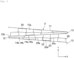
- FIG. 2 is a view showing a portion of a filter pack 3 that is folded as viewed in a direction in which folds 12 and 13 of pleats extend (upper view).
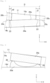
- FIG. 3 is a partially enlarged view of FIG. 2 .
- the air filter 1 has the filter pack 3 and a frame 5.
- the frame 5 surrounds the filter pack 3 so that the folds 12 and 13 of a filter medium 11 of the filter pack 3 are arranged on upstream and downstream sides in a direction of airflow (X direction) passing through the filter medium 11.
- X direction a direction of airflow
- a fold located on the upstream side of the airflow (-X direction) is referred to as the fold 12
- a fold located on the downstream side of the airflow (+X direction) is referred to as the fold 13.
- the filter pack 3 has the filter medium 11 and a plurality of space maintaining members 20.
- the filter medium 11 is a member that collects fine particles in a gas.
- the filter medium 11 is used to remove, for example, dust having a particle diameter of 2.5 um or less at a concentration of 0.3 mg/m 3 or less.
- the filter medium 11 has, for example, a collection efficiency of 80% or more according to a counting method, a pressure loss of 79 to 493 Pa, and a dust holding capacity (dust holding amount) of 200 to 800 g/m 2 .
- the counting method measurement is performed by allowing air containing particles of any of atmospheric dust, polyalphaolefin (PAO), and silica having a particle diameter of 0.3 um to pass therethrough.
- the dust holding capacity is the amount of dust collected by the filter until a given final pressure loss is reached.
- the filter medium 11 may also be, for example, a filter medium for a HEPA filter, a filter medium for a ULPA filter, or a filter medium for a gas removal filter.
- the filter medium 11 is, for example, a fibrous body made of a glass fiber, an organic fiber, or a mixed fiber of these fibers, and is, for example, a nonwoven fabric or felt.
- the filter medium 11 made of a glass fiber is produced, for example, by papermaking with a wet method or a dry method.
- the filter medium 11 made of an organic fiber is produced, for example, by a spun-bond method, a melt-blow method, a thermal bond method, a chemical bond method, or the like.
- the filter medium 11 may be, for example, a laminate of a plurality of nonwoven fabrics having different collection efficiencies.
- the filter medium 11 is subjected to a pleating process into an approximate V shape so that mountain folds and valley folds are alternately repeated.
- the pleating process is performed using a reciprocating-type or rotarytype folding machine or the like.
- the filter medium 11 has the folds 12 and 13 parallel to each other on the upstream and downstream sides of the airflow due to the pleating process. Further, the filter medium 11 has a plurality of pairs of ventilation surfaces 14 (ventilation surfaces 14a and 14b) that are continuous with the fold 12 or 13 therebetween and face each other approximately in a Y direction.
- the ventilation surface 14 has a plurality of (at least one) pairs of upstream ventilation surfaces 15a and 15b and pairs of downstream ventilation surfaces 16a and 16b.
- the pair of upstream ventilation surfaces 15a and 15b are ventilation surfaces 14 which face each other via the fold 13 on the downstream side therebetween and into which airflow flows.
- the pair of downstream ventilation surfaces 16a and 16b are ventilation surfaces 14 which face each other via the fold 12 on the upstream side therebetween and from which airflow flows out.
- the upstream ventilation surfaces 15a and 15b and the downstream ventilation surfaces 16a and 16b are simply referred to as the ventilation surfaces 14 when they are not distinguished from each other.
- the space maintaining members 20 are a plurality of members that maintain a space (pleat space) set between the pair of ventilation surfaces 14 of the filter medium 11.
- the space maintaining members 20 are intermittently formed on the ventilation surfaces 14 in a direction (approximate X direction) orthogonal to a direction along the folds 12 and 13. In FIG. 2 , for example, three space maintaining members 20 are intermittently formed on the ventilation surface 14a.
- At least one space maintaining member 20 formed on one side of the pair of ventilation surfaces 14 is in contact at two or more places with at least one space maintaining member 20 formed on the other side of the pair of ventilation surfaces 14.
- a space maintaining member 20a formed on the ventilation surface 14b is in contact with a plurality of space maintaining members 20b and 20c adjacent thereto formed on the ventilation surface 14a at two contact places 23, 23.
- the space maintaining member 20 formed on one side of the pair of ventilation surfaces 14 has a facing surface 25 facing to the space maintaining member 20 formed on the other side of the pair of ventilation surfaces 14.
- the facing surface 25 is, for example, a flat tip surface of the space maintaining member 20.
- a sum of lengths d1 and d2 thereof along an approximate X direction in contact with facing surfaces 25b and 25c of the space maintaining members 20b and 20c formed on the ventilation surface 14a is preferably 1% or more and 10% or less of a length D along an approximate X direction of the facing surface 25a.
- the contact place 23 is small, and the effect of maintaining the space may be reduced.
- the dimension of the space maintaining member 20 becomes large, and as a result, the area covering the ventilation surface 14 becomes large, resulting in an increase in pressure loss when the filter is used.
- the space maintaining members 20 have different heights (lengths in an approximate Y direction) depending on the pleat space. Specifically, in FIG. 2 , the pleat space between the pair of ventilation surfaces 14a and 14b increases from the fold 12 toward the fold 13, and therefore, the height of the space maintaining member 20 on a fold 12 side is small, and the height of the space maintaining member 20 on a fold 13 side is large.
- the space maintaining member 20 is made of, for example, a thermoplastic resin called a hot-melt adhesive.
- a thermoplastic resin include polyamidebased, urethane-based, and olefin-based thermoplastic resins.
- the space maintaining member 20 is formed, for example, by directly applying a hot-melt adhesive to the filter medium 11 approximately in the X direction of the filter medium 11 using a gun filled with a softened hot-melt adhesive. Further, the space maintaining member 20 may be formed, for example, by adhering a solidified hot-melt adhesive to the filter medium 11 other than direct application. Alternatively, the space maintaining member 20 may be made of other material such as a ceramic.
- the space maintaining member 20 formed on one side of the pair of ventilation surfaces 14 is in contact at two places with the space maintaining member 20 formed on the other side of the pair of ventilation surfaces 14. Therefore, in the filter pack 3, the pleat space is easily maintained as compared with the case where it is in contact at one place. That is, when the space maintaining member 20 is in contact only at one place, for example, the space maintaining members 20 arranged on each side of the pair of ventilation surfaces 14 may be out of position due to production errors, and there may be a case where the space maintaining members 20 are not in contact with each other. In this case, the pleat space is not maintained, and the filter efficiency may decrease.
- the space maintaining members 20 are in contact at two places, and therefore, the space maintaining members 20 facing each other can reliably contact each other and are supported at two places.
- friction or the like acts at the contact places 23, so that there is also an advantage that the space maintaining members 20 are less likely to be out of position. Therefore, in such a filter pack 3 and an air filter 1, the pleat spaces can be suitably maintained while suppressing an increase in pressure loss.
- one space maintaining member 20 formed on one side of the pair of ventilation surfaces 14 is in contact at one place with each of the plurality of space maintaining members 20 adjacent thereto formed on the other side of the pair of ventilation surfaces 14 is described.
- one space maintaining member 20 formed on one side of the pair of ventilation surfaces 14 may be in contact at a plurality of places with one space maintaining member 20 formed on the other side of the pair of ventilation surfaces 14.
- one space maintaining member 20d formed on the other side of a pair of ventilation surfaces 14d has protruding shapes 26 protruding in a height direction at two places.
- a space maintaining member 20e formed on one side of a pair of ventilation surfaces 14e is in contact at two places by being in contact with the protruding shapes 26 at two places.
- the number of contact places 23 may be two or more.
- a space maintaining member 20f formed on one side of the ventilation surface 14f may be provided in a dot shape (approximately hemispherical shape) with a short length approximately in the X direction.
- a space maintaining member 20g formed on the other side of the ventilation surface 14g is in contact at two or more places with two or more adjacent space maintaining members 20f facing thereto.
- the filter pack can be included in the scope of the filter pack of the invention.
- the space maintaining members 20 are intermittently formed approximately in the X direction on any of the upstream ventilation surfaces 15a and 15b and the downstream ventilation surfaces 16a and 16b is described.
- the space maintaining members 20 may be continuously formed approximately in the X direction on the downstream ventilation surfaces 16a and 16b.
- FIG. 6 shows a filter pack 103 as a third modification and is a view showing a portion of the filter pack 103 that is folded as viewed in a direction in which folds of pleats extend.
- FIGS. 6 and 7 configurations and parts corresponding to those of the filter pack 3 are denoted by the same reference numerals, and overlapping description will be omitted.
- the difference between the filter pack 103 and the filter pack 3 is that space maintaining members 120b formed on downstream ventilation surfaces 116a and 116b are continuously formed, not intermittently, approximately in the X direction. That is, the space maintaining members 120b adjacent to each other approximately in the X direction are formed in close contact with each other without forming a gap.
- a pair of upstream ventilation surfaces 115a and 115b of the filter pack 103 may swell toward the outflow side due to the airflow that flows in, which may increase the pleat space between the pair of upstream ventilation surfaces 115a and 115b.
- space maintaining members 120a and 120b are formed so as to increase the strength of the filter medium 11 while taking into account the advantage of suppressing an increase in pressure loss as in the filter pack 3. That is, the space maintaining members 120a formed on the upstream ventilation surfaces 115a and 115b are intermittently formed approximately in the X direction, and the space maintaining members 120b formed on the downstream ventilation surfaces 116a and 116b are continuously formed approximately in the X direction.
- the space maintaining member 120b is in contact with a facing surface 125 of the space maintaining member 120b facing thereto at a rise 121 with respect to the downstream ventilation surfaces 116a and 116b from the upstream side to the downstream side.
- the space maintaining member 120b can prevent the pair of upstream ventilation surfaces 115a and 115b from swelling toward the outflow side while ensuring the ventilation area, so that the pleat space at the start of use can be maintained. Further, since the strength of the filter pack 103 is increased, the stability of the shape is improved even during continuous ventilation, and as a result, an increase in pressure loss can be suppressed.
- one space maintaining member 120b may be formed in an elongated shape over the downstream ventilation surfaces 116a and 116b approximately in the X direction.
Landscapes
- Chemical & Material Sciences (AREA)
- Chemical Kinetics & Catalysis (AREA)
- Filtering Of Dispersed Particles In Gases (AREA)
- Filtering Materials (AREA)
Applications Claiming Priority (2)
| Application Number | Priority Date | Filing Date | Title |
|---|---|---|---|
| JP2021066458 | 2021-04-09 | ||
| PCT/JP2022/015356 WO2022215590A1 (ja) | 2021-04-09 | 2022-03-29 | フィルタパックおよびそれを備えるエアフィルタ |
Publications (2)
| Publication Number | Publication Date |
|---|---|
| EP4306201A1 true EP4306201A1 (de) | 2024-01-17 |
| EP4306201A4 EP4306201A4 (de) | 2025-03-26 |
Family
ID=83545514
Family Applications (1)
| Application Number | Title | Priority Date | Filing Date |
|---|---|---|---|
| EP22784574.0A Pending EP4306201A4 (de) | 2021-04-09 | 2022-03-29 | Filterpaket und damit ausgestatteter luftfilter |
Country Status (7)
| Country | Link |
|---|---|
| US (1) | US20240181378A1 (de) |
| EP (1) | EP4306201A4 (de) |
| JP (1) | JPWO2022215590A1 (de) |
| KR (1) | KR20230167390A (de) |
| CN (1) | CN117222464A (de) |
| TW (1) | TW202304582A (de) |
| WO (1) | WO2022215590A1 (de) |
Families Citing this family (1)
| Publication number | Priority date | Publication date | Assignee | Title |
|---|---|---|---|---|
| JP2025139847A (ja) * | 2024-03-13 | 2025-09-29 | 日本無機株式会社 | オイルミスト用エアフィルタ |
Family Cites Families (22)
| Publication number | Priority date | Publication date | Assignee | Title |
|---|---|---|---|---|
| US5084178A (en) * | 1988-06-15 | 1992-01-28 | Pall Corporation | Corrugated filter arrangement with support layer and flow channels |
| ATE98892T1 (de) * | 1989-01-05 | 1994-01-15 | Camfil Ab | Filter. |
| JP3674648B2 (ja) * | 1996-05-28 | 2005-07-20 | 日本バイリーン株式会社 | フィルタ |
| JP3488589B2 (ja) * | 1997-02-10 | 2004-01-19 | 株式会社共立 | エアークリーナ |
| DE10015951C2 (de) * | 1999-12-22 | 2002-09-26 | Jacobi Systemtechnik Gmbh | Filterelement |
| JP4139121B2 (ja) * | 2002-03-28 | 2008-08-27 | 日本無機株式会社 | ジグザグ状エアフィルタ用濾材の製造方法 |
| JP4733340B2 (ja) * | 2003-04-24 | 2011-07-27 | 日本エアー・フィルター株式会社 | 折込み型エアフィルタ及びその製造方法 |
| US7169202B2 (en) * | 2003-12-24 | 2007-01-30 | 3M Innovative Properties Company | Filter assembly |
| US7661540B2 (en) * | 2003-12-30 | 2010-02-16 | Aaf Mcquay, Inc. | Method of forming spaced pleated filter material and product of same |
| JP2007098233A (ja) * | 2005-09-30 | 2007-04-19 | Nippon Muki Co Ltd | ジグザグ状エアフィルタ用濾材およびエアフィルタ |
| US20080067121A1 (en) * | 2006-09-15 | 2008-03-20 | Lpd Technologies, Inc. | Fluid filter element with reinforcing scrim |
| JP5466853B2 (ja) * | 2008-12-25 | 2014-04-09 | 日本無機株式会社 | プリーツ型エアフィルタパック及びそれを用いたエアフィルタ |
| EP2436435A4 (de) * | 2009-05-29 | 2016-05-11 | Nippon Muki Kk | Filterelement sowie doppelt gefaltetes luftfilter damit |
| DE102009040202B4 (de) * | 2009-09-07 | 2015-10-01 | Mann + Hummel Gmbh | Filter |
| JP5333550B2 (ja) * | 2011-08-31 | 2013-11-06 | ダイキン工業株式会社 | エアフィルタ用濾材及びエアフィルタユニット |
| US10730001B2 (en) * | 2014-09-08 | 2020-08-04 | Clarcor Air Filtration Products, Inc. | Filter with high dust capacity |
| JP2016087515A (ja) * | 2014-10-31 | 2016-05-23 | ダイキン工業株式会社 | 曲げ加工用エアフィルタ、エアフィルタパック、エアフィルタユニット、および、曲げ加工用エアフィルタの製造方法 |
| JP6399069B2 (ja) * | 2016-09-30 | 2018-10-03 | ダイキン工業株式会社 | エアフィルタ濾材、エアフィルタパック、およびエアフィルタユニット |
| JP7075190B2 (ja) * | 2017-09-14 | 2022-05-25 | 日本無機株式会社 | エアフィルタ、及びフィルタパック |
| JP7370695B2 (ja) * | 2018-10-17 | 2023-10-30 | 日本無機株式会社 | フィルタパック、及びエアフィルタ |
| JP7507590B2 (ja) * | 2020-03-31 | 2024-06-28 | 日本無機株式会社 | エアフィルタ、及びフィルタパック |
| JP7692913B2 (ja) * | 2020-07-16 | 2025-06-16 | 日本無機株式会社 | フィルタパックおよびそれを備えるエアフィルタ |
-
2022
- 2022-03-29 JP JP2023512958A patent/JPWO2022215590A1/ja active Pending
- 2022-03-29 EP EP22784574.0A patent/EP4306201A4/de active Pending
- 2022-03-29 WO PCT/JP2022/015356 patent/WO2022215590A1/ja not_active Ceased
- 2022-03-29 US US18/284,932 patent/US20240181378A1/en active Pending
- 2022-03-29 KR KR1020237037793A patent/KR20230167390A/ko active Pending
- 2022-03-29 CN CN202280026838.0A patent/CN117222464A/zh active Pending
- 2022-04-07 TW TW111113239A patent/TW202304582A/zh unknown
Also Published As
| Publication number | Publication date |
|---|---|
| TW202304582A (zh) | 2023-02-01 |
| WO2022215590A1 (ja) | 2022-10-13 |
| US20240181378A1 (en) | 2024-06-06 |
| EP4306201A4 (de) | 2025-03-26 |
| KR20230167390A (ko) | 2023-12-08 |
| JPWO2022215590A1 (de) | 2022-10-13 |
| CN117222464A (zh) | 2023-12-12 |
Similar Documents
| Publication | Publication Date | Title |
|---|---|---|
| CN102958582B (zh) | 空气过滤器插入体 | |
| EP3520872A1 (de) | Luftfiltermedium, luftfilterpack und luftfiltereinheit | |
| CN114040811A (zh) | 具有改进的灰尘负载的过滤介质 | |
| EP4306201A1 (de) | Filterpaket und damit ausgestatteter luftfilter | |
| KR102950666B1 (ko) | 에어 필터 | |
| JP7692913B2 (ja) | フィルタパックおよびそれを備えるエアフィルタ | |
| JP7075190B2 (ja) | エアフィルタ、及びフィルタパック | |
| JP6127411B2 (ja) | エアフィルタ | |
| US12157085B2 (en) | Filter pack and air filter | |
| JP7507590B2 (ja) | エアフィルタ、及びフィルタパック | |
| US20240238709A1 (en) | Filter | |
| KR20200137668A (ko) | 에어 필터 팩 및 그를 포함하는 에어 필터 | |
| KR102946526B1 (ko) | 여과재 및 필터 유닛 | |
| JP6276044B2 (ja) | ガスタービン吸気用エアフィルタ | |
| JP2021028057A (ja) | エアフィルタユニット | |
| WO2025205690A1 (ja) | フィルタパックおよびそれを備えるエアフィルタ | |
| JP2025151716A (ja) | フィルタパックおよびそれを備えるエアフィルタ | |
| JP2025151717A (ja) | フィルタパックおよびそれを備えるエアフィルタ | |
| WO2025192679A1 (ja) | オイルミスト用エアフィルタ | |
| JP6788460B2 (ja) | 濾材交換型フィルタ | |
| JP2017070900A (ja) | 補強エアフィルターユニット | |
| JP2007289907A (ja) | 空調フィルタのセパレータ |
Legal Events
| Date | Code | Title | Description |
|---|---|---|---|
| STAA | Information on the status of an ep patent application or granted ep patent |
Free format text: STATUS: THE INTERNATIONAL PUBLICATION HAS BEEN MADE |
|
| PUAI | Public reference made under article 153(3) epc to a published international application that has entered the european phase |
Free format text: ORIGINAL CODE: 0009012 |
|
| STAA | Information on the status of an ep patent application or granted ep patent |
Free format text: STATUS: REQUEST FOR EXAMINATION WAS MADE |
|
| 17P | Request for examination filed |
Effective date: 20231011 |
|
| AK | Designated contracting states |
Kind code of ref document: A1 Designated state(s): AL AT BE BG CH CY CZ DE DK EE ES FI FR GB GR HR HU IE IS IT LI LT LU LV MC MK MT NL NO PL PT RO RS SE SI SK SM TR |
|
| DAV | Request for validation of the european patent (deleted) | ||
| DAX | Request for extension of the european patent (deleted) | ||
| A4 | Supplementary search report drawn up and despatched |
Effective date: 20250221 |
|
| RIC1 | Information provided on ipc code assigned before grant |
Ipc: B01D 46/52 20060101AFI20250217BHEP |