EP4306094A2 - Automatic speed reducing wheel - Google Patents
Automatic speed reducing wheel Download PDFInfo
- Publication number
- EP4306094A2 EP4306094A2 EP23172022.8A EP23172022A EP4306094A2 EP 4306094 A2 EP4306094 A2 EP 4306094A2 EP 23172022 A EP23172022 A EP 23172022A EP 4306094 A2 EP4306094 A2 EP 4306094A2
- Authority
- EP
- European Patent Office
- Prior art keywords
- wheel
- bore
- sliding
- speed reducing
- roller
- Prior art date
- Legal status (The legal status is an assumption and is not a legal conclusion. Google has not performed a legal analysis and makes no representation as to the accuracy of the status listed.)
- Pending
Links
- 230000001603 reducing effect Effects 0.000 title claims abstract description 43
- 230000000903 blocking effect Effects 0.000 claims abstract description 24
- 230000005855 radiation Effects 0.000 claims abstract description 6
- 230000005484 gravity Effects 0.000 claims description 5
- 230000005489 elastic deformation Effects 0.000 claims description 3
- 241001272996 Polyphylla fullo Species 0.000 description 3
- 230000001133 acceleration Effects 0.000 description 3
- 230000000694 effects Effects 0.000 description 3
- 208000027418 Wounds and injury Diseases 0.000 description 2
- 230000006378 damage Effects 0.000 description 2
- 208000014674 injury Diseases 0.000 description 2
- 230000032683 aging Effects 0.000 description 1
- 230000007774 longterm Effects 0.000 description 1
- 238000012986 modification Methods 0.000 description 1
- 230000004048 modification Effects 0.000 description 1
- 230000000474 nursing effect Effects 0.000 description 1
Images


Classifications
-
- B—PERFORMING OPERATIONS; TRANSPORTING
- B60—VEHICLES IN GENERAL
- B60B—VEHICLE WHEELS; CASTORS; AXLES FOR WHEELS OR CASTORS; INCREASING WHEEL ADHESION
- B60B33/00—Castors in general; Anti-clogging castors
- B60B33/0078—Castors in general; Anti-clogging castors characterised by details of the wheel braking mechanism
- B60B33/0097—Castors in general; Anti-clogging castors characterised by details of the wheel braking mechanism acting permanently, e.g. for increased security on low friction surfaces
-
- B—PERFORMING OPERATIONS; TRANSPORTING
- B60—VEHICLES IN GENERAL
- B60B—VEHICLE WHEELS; CASTORS; AXLES FOR WHEELS OR CASTORS; INCREASING WHEEL ADHESION
- B60B33/00—Castors in general; Anti-clogging castors
- B60B33/0078—Castors in general; Anti-clogging castors characterised by details of the wheel braking mechanism
- B60B33/0086—Castors in general; Anti-clogging castors characterised by details of the wheel braking mechanism acting on rim or side portion of tyre
-
- A—HUMAN NECESSITIES
- A61—MEDICAL OR VETERINARY SCIENCE; HYGIENE
- A61G—TRANSPORT, PERSONAL CONVEYANCES, OR ACCOMMODATION SPECIALLY ADAPTED FOR PATIENTS OR DISABLED PERSONS; OPERATING TABLES OR CHAIRS; CHAIRS FOR DENTISTRY; FUNERAL DEVICES
- A61G5/00—Chairs or personal conveyances specially adapted for patients or disabled persons, e.g. wheelchairs
- A61G5/10—Parts, details or accessories
- A61G5/1005—Wheelchairs having brakes
- A61G5/1008—Wheelchairs having brakes for gradually slowing down the wheelchair
-
- A—HUMAN NECESSITIES
- A61—MEDICAL OR VETERINARY SCIENCE; HYGIENE
- A61G—TRANSPORT, PERSONAL CONVEYANCES, OR ACCOMMODATION SPECIALLY ADAPTED FOR PATIENTS OR DISABLED PERSONS; OPERATING TABLES OR CHAIRS; CHAIRS FOR DENTISTRY; FUNERAL DEVICES
- A61G5/00—Chairs or personal conveyances specially adapted for patients or disabled persons, e.g. wheelchairs
- A61G5/10—Parts, details or accessories
- A61G5/1005—Wheelchairs having brakes
- A61G5/1013—Wheelchairs having brakes engaging the wheel
- A61G5/1016—Wheelchairs having brakes engaging the wheel on the rim
-
- B—PERFORMING OPERATIONS; TRANSPORTING
- B60—VEHICLES IN GENERAL
- B60B—VEHICLE WHEELS; CASTORS; AXLES FOR WHEELS OR CASTORS; INCREASING WHEEL ADHESION
- B60B33/00—Castors in general; Anti-clogging castors
-
- B—PERFORMING OPERATIONS; TRANSPORTING
- B60—VEHICLES IN GENERAL
- B60B—VEHICLE WHEELS; CASTORS; AXLES FOR WHEELS OR CASTORS; INCREASING WHEEL ADHESION
- B60B33/00—Castors in general; Anti-clogging castors
- B60B33/0078—Castors in general; Anti-clogging castors characterised by details of the wheel braking mechanism
- B60B33/0094—Castors in general; Anti-clogging castors characterised by details of the wheel braking mechanism actuated automatically
-
- B—PERFORMING OPERATIONS; TRANSPORTING
- B60—VEHICLES IN GENERAL
- B60B—VEHICLE WHEELS; CASTORS; AXLES FOR WHEELS OR CASTORS; INCREASING WHEEL ADHESION
- B60B33/00—Castors in general; Anti-clogging castors
- B60B33/0036—Castors in general; Anti-clogging castors characterised by type of wheels
- B60B33/0039—Single wheels
-
- B—PERFORMING OPERATIONS; TRANSPORTING
- B60—VEHICLES IN GENERAL
- B60B—VEHICLE WHEELS; CASTORS; AXLES FOR WHEELS OR CASTORS; INCREASING WHEEL ADHESION
- B60B33/00—Castors in general; Anti-clogging castors
- B60B33/0047—Castors in general; Anti-clogging castors characterised by details of the rolling axle
- B60B33/0055—Castors in general; Anti-clogging castors characterised by details of the rolling axle the rolling axle intersects swivel axis
Definitions
- the present invention relates to wheels, and more particularly, to a wheel automatically reducing the speed when moving downhill.
- Taiwan has entered an aging society which increasingly needs long-term care service.
- hospitals or nursing organizations patients or elder people often face inconvenience of moving due to physical disabilities or body weakness, and they have to rely on walkers or wheelchairs for facilitate their movement and outdoor activities. Therefore, use of walkers or wheelchairs accordingly increases.
- Both walkers and wheelchairs are usually provided with wheels, which roll along the ground surface.
- wheels which roll along the ground surface.
- a sudden acceleration occurs due to the sliding force, resulting in the overspeed of the wheels.
- the user is usually unable to immediately respond, failing to control the brake mechanism for stopping the wheel in time, such that the user easily falls, or suffers from the accidental overturn of the walker or wheelchair, which poses high risks to the weak, the elder, or the disabled with weaker controlling capability. It is desirable to resolve such issues.
- the present invention based on the idea of creation through various discussions, trial sample tests, revisions, and improvements, discloses an automatic speed reducing wheel.
- the present invention provides an automatic speed reducing wheel, comprising:
- the automatic speed reducing wheel of the present invention provides an automatic speed reducing function to avoid a sudden acceleration, thereby preventing the user from injury and increasing the safety of the user.
- an automatic speed reducing wheel 1 of the present invention comprises a wheel unit 10 and a speed reducing unit 20.
- the wheel unit 10 comprises a wheel seat 11, a wheel axle 12 passing through the wheel seat 11, and a roller 13 rotating about the wheel axle 12.
- Two side boards 111 extend from the wheel seat 11, and a through hole 1111 pass through the two side boards 111, such that the wheel axle 12 passes through the through hole 1111.
- the wheel axle 12 comprises a non-circular section 121 on one end thereof.
- the roller 13 is disposed between the two side boards 111.
- the roller 13 comprises a wheel frame 131 whose outer periphery is combined with an outer wheel 132.
- the wheel frame 131 comprises an axle bore 1311 passing through the center thereof.
- the wheel axle 12 passes through the axle bore 1311. Therefore, the roller 13 is configured to freely rotate about the wheel axle 12.
- a plurality of blockers 1312 is circularly disposed on one side of the wheel frame 131 in adjacent to an edge thereof in a radiation shape arrangement. The plurality of blockers 1312 rotates along with the roller 13.
- the speed reducing unit 20 comprises a fixing seat 21, a sliding member 22, and a protection cover 23.
- the fixing seat 21 is disposed between the two side boards 111 and is arranged on one side of the roller 13.
- the fixing seat 21 comprises a fixing bore 211 and a sliding bore 212.
- the fixing bore 211 is mounted around the non-circular section 121 of the wheel axle 12 and fixed thereon.
- the sliding bore 212 is normally positioned in a horizontal arrangement.
- the sliding member 22 is slidably disposed in the sliding bore 212, such that the sliding member 22 is able to slide along the sliding bore 212.
- the sliding member 22 comprises a sliding body 221.
- the sliding body 221 comprises a sheet shaped elastic portion 222 connected with a front end of the sliding body 221.
- the elastic portion 222 comprises a blocking portion 223 connected with a front end of the elastic portion 222.
- the protection cover 23 is disposed between the two side boards 111 of the wheel seat 11 and is arranged on one side of the roller 13.
- the protection cover 23 covers the fixing seat 21 and the sliding member 22.
- the protection cover 23 comprises a combination bore 231 passing through the center thereof, such that the combination bore 231 is mounted around the non-circular section 121 and fixed thereon.
- the automatic speed reducing wheel 1 is able to be installed on a moving vehicle such as a wheelchair 2 (as shown by Fig. 7 ) or a mobility aid 3 (as shown by Fig. 8 ).
- a moving vehicle such as a wheelchair 2 (as shown by Fig. 7 ) or a mobility aid 3 (as shown by Fig. 8 ).
- the blocking portion 223 of the sliding member 22 is away from the rotation route of the plurality of blockers 1312 (as shown by Fig. 4 ), so that the wheelchair 2 or the mobility aid 3 is able to normally move.
- the sliding bore 212 slants downward by an inclination angle.
- the sliding member 22 slides along the sliding bore 212 due to the effect of the gravity force, such that the blocking portion 223 of the sliding member 22 protrudes out of an outer side of the sliding bore 212 to interrupt the rotation route of the plurality of blockers 1312, whereby the blocking portion 223 hinders the rotation of the blockers 1312 with the elastic deformation and resilience of the elastic portion 222, so that the plurality of blockers 1312 passes and hits the blocking portion 223 one by one, achieving a speed reducing effect.
- the automatic speed reducing wheel 1 in accordance with another embodiment of the present invention is provided, comprising a wheel unit 10 and a speed reducing unit 20.
- the wheel unit 10 comprises a wheel seat 11, a wheel axle 12 passing through the wheel seat 11, and a roller 13 rotating about the wheel axle 12.
- Two side boards 111 extend from the wheel seat 11, and a through hole 1111 passes through the two side boards 111, such that the wheel axle 12 passes through the through hole 1111.
- the roller 13 is disposed between the two side boards 111.
- the roller 13 comprises a wheel frame 131 whose outer periphery is combined with an outer wheel 132.
- the wheel frame 131 comprises an axle bore 1311 passing through the center thereof.
- the wheel axle 12 passes through the axle bore 1311. Therefore, the roller 13 is configured to freely rotate about the wheel axle 12.
- a plurality of elastic blockers 1313 is circularly disposed on one side of the wheel frame 131 in adjacent to an edge thereof in a radiation shape arrangement. The plurality of elastic blockers 1313 rotates along with the roller 13.
- the speed reducing unit 20 comprises a fixing seat 24, a sliding member 25, and a side cover 26.
- the fixing seat 24 is disposed on one side of the roller 13.
- the fixing seat 24 comprises a sliding bore 241.
- the sliding member 25 is slidably disposed in the sliding bore 241.
- the sliding member 25 comprises a position limiting groove 251 disposed on the middle section thereof.
- the position limiting groove 251 allows the sliding member 25 to slide along the sliding bore 241 in a position limiting range.
- the sliding member 25 comprises a blocking portion 252 on the front end thereof.
- the side cover 26 is disposed on one side of the roller 13 and is combined with the fixing seat 24.
- the side cover 26 covers the fixing seat 21 and the sliding member 22, such that the sliding bore 241 of the fixing seat 24 is normally positioned in a horizontal arrangement.
- the side cover 26 comprises a through bore 261 passing through the center thereof, and the wheel axle 12 passes through the through bore 261.
- the side cover 26 comprises an arc bore 262, by which two screws 263 pass to be fastened on one of the side boards 111, whereby the side cover 26 is connected with the wheel seat 11, and the wheel seat 11 is able to sway with respect to the side cover 26 within the arc bore 262.
- the position limiting groove 251 comprises a first end 2511 and a second end 2512.
- the position limiting range is the interval range between the first end 2511 and the second end 2512.
- the automatic speed reducing wheel 1 is able to be installed on a moving vehicle such as a wheelchair 2 (as shown by Fig. 7 ) or a mobility aid 3 (as shown by Fig. 8 ).
- a moving vehicle such as a wheelchair 2 (as shown by Fig. 7 ) or a mobility aid 3 (as shown by Fig. 8 ).
- the blocking portion 252 of the sliding member 25 is away from the rotation route of the plurality of the elastic blockers 1313 (as shown by Fig. 11 ), so that the wheelchair 2 or the mobility aid 3 is able to normally move.
- the sliding bore 241 slants downward by an inclination angle.
- the sliding member 25 slides along the sliding bore 241 due to the effect of the gravity force, such that the blocking portion 252 of the sliding member 25 protrudes out of an outer side of the sliding bore 241 to interrupt the rotation route of the plurality of elastic blockers 1313, whereby the blocking portion 252 hinders the rotation of the plurality of elastic blockers 1313 with the elastic deformation and resilience of the elastic blockers 1313, so that the elastic blockers 1313 pass and hit the blocking portion 252 one by one and then recover, achieving a speed reducing effect.
- the position limiting groove 251 comprises a first end 2511 and a second end 2512, and the side edge of the wheel axle 12 is engaged with the position limiting groove 251.
- the sliding bore 241 slants downward by an inclination angle
- the second end 2512 of the position limiting groove 251 abuts against the side edge of the wheel axle 12, such that the sliding member 25 is able to move within the position limiting range, preventing the sliding member 25 from being separated from the sliding bore 241.
- the present invention achieves following advantages.
- the automatic speed reducing wheel 1 is able to be installed on a moving vehicle such as a wheelchair 2 or mobility aid 3.
- a moving vehicle such as a wheelchair 2 or mobility aid 3.
- the present invention provides an automatic speed reducing function to avoid a sudden acceleration, thereby preventing the user from injury during the downhill movement and increasing the safety of the user.
Landscapes
- Engineering & Computer Science (AREA)
- Mechanical Engineering (AREA)
- Health & Medical Sciences (AREA)
- Life Sciences & Earth Sciences (AREA)
- Animal Behavior & Ethology (AREA)
- General Health & Medical Sciences (AREA)
- Public Health (AREA)
- Veterinary Medicine (AREA)
- Motorcycle And Bicycle Frame (AREA)
- Braking Arrangements (AREA)
- Handcart (AREA)
- Friction Gearing (AREA)
Abstract
Description
- The present invention relates to wheels, and more particularly, to a wheel automatically reducing the speed when moving downhill.
- Taiwan has entered an aging society which increasingly needs long-term care service. In hospitals or nursing organizations, patients or elder people often face inconvenience of moving due to physical disabilities or body weakness, and they have to rely on walkers or wheelchairs for facilitate their movement and outdoor activities. Therefore, use of walkers or wheelchairs accordingly increases.
- Both walkers and wheelchairs are usually provided with wheels, which roll along the ground surface. However, when the walker or wheelchair is applied to move downhill, a sudden acceleration occurs due to the sliding force, resulting in the overspeed of the wheels. In this case, the user is usually unable to immediately respond, failing to control the brake mechanism for stopping the wheel in time, such that the user easily falls, or suffers from the accidental overturn of the walker or wheelchair, which poses high risks to the weak, the elder, or the disabled with weaker controlling capability. It is desirable to resolve such issues.
- For improving the issues of the conventional wheels, the present invention, based on the idea of creation through various discussions, trial sample tests, revisions, and improvements, discloses an automatic speed reducing wheel.
- The present invention provides an automatic speed reducing wheel, comprising:
- a wheel unit having a wheel seat, a wheel axle passing through the wheel seat, and a roller rotating about the wheel axle, the wheel seat comprising a through hole through which the wheel axle passes, the wheel axle comprising a non-circular section on one end thereof, the roller comprising a wheel frame whose outer periphery is combined with an outer wheel, the wheel frame comprising an axle bore passing through a center thereof, the wheel axle passing through the axle bore, the roller being configured to freely rotate about the wheel axle, a plurality of blockers disposed on one side of the wheel frame in adjacent to an edge thereof in a radiation shape arrangement, the plurality of blockers rotating along with the roller; and
- a speed reducing unit comprising a fixing seat and a sliding member, the fixing seat comprising a fixing bore and a sliding bore, the fixing bore mounted around the non-circular section of the wheel axle and fixed thereon, the fixing seat located on one side of the roller, the sliding member slidably disposed in the sliding bore, the sliding member comprising a sliding body, the sliding body comprising an elastic portion connected with a front end thereof, the elastic portion comprising a blocking portion connected with a front end thereof; when the roller moves downhill, the sliding bore slants downward by an inclination angle, and the sliding member slides along the sliding bore due to a gravity force, such that the blocking portion of the sliding member protrudes out of an outer side of the sliding bore to interrupt a rotation route of the blockers, whereby the blockers pass and hit the blocking portion one by one, such that a cooperation between the blocking portion and an elasticity of the elastic portion achieves a speed reducing effect.
- When the roller moves downhill, the automatic speed reducing wheel of the present invention provides an automatic speed reducing function to avoid a sudden acceleration, thereby preventing the user from injury and increasing the safety of the user.
-
-
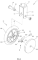
Fig. 1 is a perspective view in accordance with an embodiment of the present invention. -
Fig. 2 is an exploded view of the present invention. -
Fig. 3 is a perspective view of the fixing seat and the sliding member of the present invention. -
Fig. 4 is a sectional view of the present invention. -
Fig. 5 is a schematic view illustrating the automatic speed reducing operation when moving downhill. -
Fig. 6 is another schematic view illustrating the automatic speed reducing operation when moving downhill. -
Fig. 7 is a schematic view illustrating the usage of the present invention installed on a wheelchair. -
Fig. 8 is a schematic view illustrating the usage of the present invention installed on a mobility aid. -
Fig. 9 is a perspective view in accordance with another embodiment of the present invention. -
Fig. 10 is an exploded view in accordance with another embodiment of the present invention. -
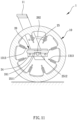
Fig. 11 is a sectional view in accordance with another embodiment of the present invention. -
Fig. 12 is a schematic view illustrating the automatic speed reducing operation when moving downhill in accordance with another embodiment of the present invention. -
Fig. 13 is another schematic view illustrating the automatic speed reducing operation when moving downhill in accordance with another embodiment of the present invention. - The aforementioned and further advantages and features of the present invention will be understood by reference to the description of the preferred embodiment in conjunction with the accompanying drawings where the components are illustrated based on a proportion for explanation but not subject to the actual component proportion.
- The following content is illustrated in conjunction with the drawings of the preferable embodiments of the present invention, so as to enable people skilled in the art of the present invention to implement the present invention according to the specification.
- Referring to
Fig. 1 to Fig. 4 , an automaticspeed reducing wheel 1 of the present invention comprises awheel unit 10 and aspeed reducing unit 20. - The
wheel unit 10 comprises awheel seat 11, awheel axle 12 passing through thewheel seat 11, and aroller 13 rotating about thewheel axle 12. Twoside boards 111 extend from thewheel seat 11, and a throughhole 1111 pass through the twoside boards 111, such that thewheel axle 12 passes through the throughhole 1111. Thewheel axle 12 comprises anon-circular section 121 on one end thereof. Theroller 13 is disposed between the twoside boards 111. Theroller 13 comprises awheel frame 131 whose outer periphery is combined with anouter wheel 132. Thewheel frame 131 comprises anaxle bore 1311 passing through the center thereof. Thewheel axle 12 passes through the axle bore 1311. Therefore, theroller 13 is configured to freely rotate about thewheel axle 12. A plurality ofblockers 1312 is circularly disposed on one side of thewheel frame 131 in adjacent to an edge thereof in a radiation shape arrangement. The plurality ofblockers 1312 rotates along with theroller 13. - The
speed reducing unit 20 comprises afixing seat 21, a slidingmember 22, and aprotection cover 23. Thefixing seat 21 is disposed between the twoside boards 111 and is arranged on one side of theroller 13. Thefixing seat 21 comprises afixing bore 211 and asliding bore 212. Thefixing bore 211 is mounted around thenon-circular section 121 of thewheel axle 12 and fixed thereon. Thesliding bore 212 is normally positioned in a horizontal arrangement. The slidingmember 22 is slidably disposed in thesliding bore 212, such that the slidingmember 22 is able to slide along thesliding bore 212. The slidingmember 22 comprises asliding body 221. Thesliding body 221 comprises a sheet shapedelastic portion 222 connected with a front end of thesliding body 221. Theelastic portion 222 comprises a blockingportion 223 connected with a front end of theelastic portion 222. Theprotection cover 23 is disposed between the twoside boards 111 of thewheel seat 11 and is arranged on one side of theroller 13. Theprotection cover 23 covers thefixing seat 21 and the slidingmember 22. Theprotection cover 23 comprises acombination bore 231 passing through the center thereof, such that thecombination bore 231 is mounted around thenon-circular section 121 and fixed thereon. - In use, the automatic
speed reducing wheel 1 is able to be installed on a moving vehicle such as a wheelchair 2 (as shown byFig. 7 ) or a mobility aid 3 (as shown byFig. 8 ). When thewheelchair 2 or themobility aid 3 move on a level ground, the blockingportion 223 of the slidingmember 22 is away from the rotation route of the plurality of blockers 1312 (as shown byFig. 4 ), so that thewheelchair 2 or themobility aid 3 is able to normally move. Referring toFig. 5 andFig. 6 , when thewheelchair 2 or themobility aid 3 moves downhill, the sliding bore 212 slants downward by an inclination angle. The slidingmember 22 slides along the slidingbore 212 due to the effect of the gravity force, such that the blockingportion 223 of the slidingmember 22 protrudes out of an outer side of the slidingbore 212 to interrupt the rotation route of the plurality ofblockers 1312, whereby the blockingportion 223 hinders the rotation of theblockers 1312 with the elastic deformation and resilience of theelastic portion 222, so that the plurality ofblockers 1312 passes and hits the blockingportion 223 one by one, achieving a speed reducing effect. - Referring to
Fig. 9 to Fig. 11 , the automaticspeed reducing wheel 1 in accordance with another embodiment of the present invention is provided, comprising awheel unit 10 and aspeed reducing unit 20. - The
wheel unit 10 comprises awheel seat 11, awheel axle 12 passing through thewheel seat 11, and aroller 13 rotating about thewheel axle 12. Twoside boards 111 extend from thewheel seat 11, and a throughhole 1111 passes through the twoside boards 111, such that thewheel axle 12 passes through the throughhole 1111. Theroller 13 is disposed between the twoside boards 111. Theroller 13 comprises awheel frame 131 whose outer periphery is combined with anouter wheel 132. Thewheel frame 131 comprises anaxle bore 1311 passing through the center thereof. Thewheel axle 12 passes through theaxle bore 1311. Therefore, theroller 13 is configured to freely rotate about thewheel axle 12. A plurality ofelastic blockers 1313 is circularly disposed on one side of thewheel frame 131 in adjacent to an edge thereof in a radiation shape arrangement. The plurality ofelastic blockers 1313 rotates along with theroller 13. - The
speed reducing unit 20 comprises a fixingseat 24, a slidingmember 25, and aside cover 26. The fixingseat 24 is disposed on one side of theroller 13. The fixingseat 24 comprises a slidingbore 241. The slidingmember 25 is slidably disposed in the slidingbore 241. The slidingmember 25 comprises aposition limiting groove 251 disposed on the middle section thereof. Theposition limiting groove 251 allows the slidingmember 25 to slide along the slidingbore 241 in a position limiting range. The slidingmember 25 comprises a blockingportion 252 on the front end thereof. The side cover 26 is disposed on one side of theroller 13 and is combined with the fixingseat 24. The side cover 26 covers the fixingseat 21 and the slidingmember 22, such that the slidingbore 241 of the fixingseat 24 is normally positioned in a horizontal arrangement. The side cover 26 comprises a throughbore 261 passing through the center thereof, and thewheel axle 12 passes through the throughbore 261. The side cover 26 comprises an arc bore 262, by which twoscrews 263 pass to be fastened on one of theside boards 111, whereby theside cover 26 is connected with thewheel seat 11, and thewheel seat 11 is able to sway with respect to theside cover 26 within the arc bore 262. Therein, theposition limiting groove 251 comprises afirst end 2511 and asecond end 2512. The position limiting range is the interval range between thefirst end 2511 and thesecond end 2512. - In use, the automatic
speed reducing wheel 1 is able to be installed on a moving vehicle such as a wheelchair 2 (as shown byFig. 7 ) or a mobility aid 3 (as shown byFig. 8 ). When thewheelchair 2 or themobility aid 3 move on a level ground, the blockingportion 252 of the slidingmember 25 is away from the rotation route of the plurality of the elastic blockers 1313 (as shown byFig. 11 ), so that thewheelchair 2 or themobility aid 3 is able to normally move. Referring toFig. 12 andFig. 13 , when thewheelchair 2 or themobility aid 3 moves downhill, the slidingbore 241 slants downward by an inclination angle. The slidingmember 25 slides along the slidingbore 241 due to the effect of the gravity force, such that the blockingportion 252 of the slidingmember 25 protrudes out of an outer side of the slidingbore 241 to interrupt the rotation route of the plurality ofelastic blockers 1313, whereby the blockingportion 252 hinders the rotation of the plurality ofelastic blockers 1313 with the elastic deformation and resilience of theelastic blockers 1313, so that theelastic blockers 1313 pass and hit the blockingportion 252 one by one and then recover, achieving a speed reducing effect. - Further, referring to
Fig. 11 to Fig. 13 , theposition limiting groove 251 comprises afirst end 2511 and asecond end 2512, and the side edge of thewheel axle 12 is engaged with theposition limiting groove 251. When the slidingbore 241 slants downward by an inclination angle, thesecond end 2512 of theposition limiting groove 251 abuts against the side edge of thewheel axle 12, such that the slidingmember 25 is able to move within the position limiting range, preventing the slidingmember 25 from being separated from the slidingbore 241. - With the foregoing configuration, the present invention achieves following advantages.
- The automatic
speed reducing wheel 1 is able to be installed on a moving vehicle such as awheelchair 2 ormobility aid 3. When the moving vehicle moves downhill, the present invention provides an automatic speed reducing function to avoid a sudden acceleration, thereby preventing the user from injury during the downhill movement and increasing the safety of the user. - Although particular embodiments of the present invention have been described in detail for purposes of illustration, various modifications and enhancements may be made without departing from the scope of the present invention. Accordingly, the present invention is not to be limited except as by the appended claims.
Claims (9)
- An automatic speed reducing wheel (1), comprising:a wheel unit (10) having a wheel seat (11), a wheel axle (12) passing through the wheel seat (11), and a roller (13) rotating about the wheel axle (12), the wheel seat (11) comprising a through hole (1111) through which the wheel axle (12) passes, the wheel axle (12) comprising a non-circular section (121) on one end thereof, the roller (13) comprising a wheel frame (131) whose outer periphery is combined with an outer wheel (132), the wheel frame (131) comprising an axle bore (1311) passing through a center thereof, the wheel axle (12) passing through the axle bore (1311), the roller (13) being configured to freely rotate about the wheel axle (12), a plurality of blockers (1312) disposed on one side of the wheel frame (131) in adjacent to an edge thereof in a radiation shape arrangement, the plurality of blockers (1312) being configured to rotate along with the roller (13); anda speed reducing unit (20) comprising a fixing seat (21) and a sliding member (22), the fixing seat (21) comprising a fixing bore (211) and a sliding bore (212), the fixing bore (211) mounted around the non-circular section (121) of the wheel axle (12) and fixed thereon, the fixing seat (21) located on one side of the roller (13), the sliding member (22) slidably disposed in the sliding bore (212), the sliding member (22) comprising a sliding body (221), the sliding body (221) comprising an elastic portion (222) connected with a front end thereof, the elastic portion (222) comprising a blocking portion (223) connected with a front end thereof; when the roller (13) moves downhill, the sliding bore (212) slants downward by an inclination angle, and the sliding member (22) slides along the sliding bore (212) due to a gravity force, such that the blocking portion (223) of the sliding member (22) protrudes out of an outer side of the sliding bore (212) to interrupt a rotation route of the blockers (1312), whereby the blockers (1312) pass and hit the blocking portion (223) one by one, such that a cooperation between the blocking portion (223) and an elasticity of the elastic portion (222) achieves a speed reducing effect.
- The automatic speed reducing wheel (1) of claim 1, wherein the wheel seat (11) comprises two side boards (111) extending therefrom; the fixing seat (21) is disposed between the two side boards (111).
- The automatic speed reducing wheel (1) of claim 1, wherein the sliding bore (212) is normally positioned in a horizontal arrangement.
- The automatic speed reducing wheel (1) of claim 1, wherein the elastic portion (222) is formed in a sheet shape.
- The automatic speed reducing wheel (1) of claim 1, wherein the speed reducing unit (20) comprises a protection cover (23); the protection cover (23) is disposed on one side of the roller (13) and covers the fixing seat (21) and the sliding member (22); the protection cover (23) comprises a combination bore (231) passing through a center thereof, such that the combination bore (231) is mounted around the non-circular section (121) and fixed thereon.
- An automatic speed reducing wheel (1), comprising:a wheel unit (10) having a wheel seat (11), a wheel axle (12) passing through the wheel seat (11), and a roller (13) rotating about the wheel axle (12), the wheel seat (11) comprising a through hole (1111) through which the wheel axle (12) passes, the roller (13) comprising a wheel frame (131) whose outer periphery is combined with an outer wheel (132), the wheel frame (131) comprising an axle bore (1311) passing through a center thereof, the wheel axle (12) passing through the axle bore (1311), the roller (13) being configured to freely rotate about the wheel axle (12), a plurality of elastic blockers (1313) disposed on one side of the wheel frame (131) in adjacent to an edge thereof in a radiation shape arrangement, the plurality of elastic blockers (1313) being configured to rotate along with the roller (13); anda speed reducing unit (20) comprising a fixing seat (24) and a sliding member (25), the fixing seat (24) disposed on one side of the roller (13), the fixing seat (24) comprising a sliding bore (241), the sliding member (25) slidably disposed in the sliding bore (241), the sliding member (25) comprising a blocking portion (252) on a front end thereof; when the roller (13) moves downhill, the sliding bore (241) slants downward by an inclination angle, and the sliding member (25) slides along the sliding bore (241) due to a gravity force, such that the blocking portion (252) of the sliding member (25) protrudes out of an outer side of the sliding bore (241) to interrupt a rotation route of the elastic blockers (1313), whereby the blocking portion (252) hinders the elastic blockers (1313) with an elastic deformation and resilience of the elastic blockers (1313), so that the elastic blockers (1313) pass and hit the blocking portion (252) one by one and then recover, achieving a speed reducing effect.
- The automatic speed reducing wheel (1) of claim 6, wherein the sliding member (25) comprises a position limiting groove (251) disposed on a middle section thereof; the position limiting groove (251) allows the sliding member (25) to slide along the sliding bore (241) in a position limiting range.
- The automatic speed reducing wheel (1) of claim 6, wherein the sliding bore (241) is normally positioned in a horizontal arrangement.
- The automatic speed reducing wheel (1) of claim 6, wherein the wheel seat (11) comprises two side boards (111) extending therefrom; the speed reducing unit (20) comprises a side cover (26) disposed on one side of the roller (13); the side cover (26) is combined with the fixing seat (24), and covers the fixing seat (24) and the sliding member (25); the side cover (26) comprises a through bore (261) passing through a center thereof, and the wheel axle (12) passes through the through bore (261); the side cover (26) comprises an arc bore (262), by which two screws (263) pass to be fastened on one of the side boards (111), whereby the side cover (26) is connected with the wheel seat (11), and the wheel seat (11) is able to sway with respect to the side cover (26) within the arc bore (262).
Applications Claiming Priority (1)
| Application Number | Priority Date | Filing Date | Title |
|---|---|---|---|
| TW111126252A TWI795326B (en) | 2022-07-13 | 2022-07-13 | Automatic reduction wheel body |
Publications (2)
| Publication Number | Publication Date |
|---|---|
| EP4306094A2 true EP4306094A2 (en) | 2024-01-17 |
| EP4306094A3 EP4306094A3 (en) | 2024-02-14 |
Family
ID=86330629
Family Applications (1)
| Application Number | Title | Priority Date | Filing Date |
|---|---|---|---|
| EP23172022.8A Pending EP4306094A3 (en) | 2022-07-13 | 2023-05-08 | Automatic speed reducing wheel |
Country Status (12)
| Country | Link |
|---|---|
| EP (1) | EP4306094A3 (en) |
| KR (1) | KR102596284B1 (en) |
| AR (1) | AR129537A1 (en) |
| AU (1) | AU2023202832B2 (en) |
| BR (1) | BR102023009201A2 (en) |
| CA (1) | CA3197862A1 (en) |
| CL (1) | CL2023001658A1 (en) |
| GB (1) | GB2620674B (en) |
| IL (1) | IL302469A (en) |
| MX (1) | MX2023008107A (en) |
| SA (1) | SA123447420B1 (en) |
| TW (1) | TWI795326B (en) |
Family Cites Families (13)
| Publication number | Priority date | Publication date | Assignee | Title |
|---|---|---|---|---|
| FR1600143A (en) * | 1968-12-31 | 1970-07-20 | ||
| CA2371409A1 (en) * | 2002-02-11 | 2003-08-11 | Michael Harcourt | Wheelchair |
| KR100539487B1 (en) | 2003-12-29 | 2005-12-28 | 부경대학교 산학협력단 | Preparation method of Ultraviolet-A (UV-A) protecting terreusinol from the biotransformation of terreusinone by the Marine-derived Streptomyces sp. |
| US7464797B2 (en) * | 2005-03-15 | 2008-12-16 | Jarvis/Pemco, Inc. | Centrifugal brakes for wheels |
| US20060207841A1 (en) * | 2005-03-15 | 2006-09-21 | Jarvis/Pemco, Inc. | Centrifugal brakes for wheels |
| TWI258366B (en) * | 2005-03-16 | 2006-07-21 | Giant Mfg Co Ltd | Assembly of frame device and transmission device of scooter capable of being rapidly detached and safely locked |
| WO2010036952A2 (en) * | 2008-09-25 | 2010-04-01 | Gatekeeper System, Inc. | Magnetically activated wheel lock mechanism |
| EP2771589B1 (en) * | 2011-10-28 | 2021-08-04 | Ree Automotive Ltd | Wheel with suspension system and centralizing unit with suspension system |
| KR20170073579A (en) * | 2017-06-21 | 2017-06-28 | 송기현 | Wheels for preventing overspeed using eddy currents |
| CN111603325A (en) * | 2019-09-25 | 2020-09-01 | 刘战军 | Multifunctional wheelchair brake |
| KR102331996B1 (en) * | 2019-12-03 | 2021-11-26 | 조경현 | Auxiliary wheel of wheel chair having centrifugal deceleration system |
| CN111692248A (en) * | 2020-06-22 | 2020-09-22 | 浙江火萌互娱信息技术有限公司 | Stall braking device for transmission shaft of electric wheelchair |
| CN214295893U (en) * | 2020-11-10 | 2021-09-28 | 佛山市画荟科技发展有限公司 | Brake with unidirectional bearing locked and unidirectional rotating roller |
-
2022
- 2022-07-13 TW TW111126252A patent/TWI795326B/en active
- 2022-11-11 KR KR1020220150792A patent/KR102596284B1/en active IP Right Grant
-
2023
- 2023-04-25 CA CA3197862A patent/CA3197862A1/en active Pending
- 2023-04-27 IL IL302469A patent/IL302469A/en unknown
- 2023-05-06 AU AU2023202832A patent/AU2023202832B2/en active Active
- 2023-05-08 EP EP23172022.8A patent/EP4306094A3/en active Pending
- 2023-05-12 BR BR102023009201-2A patent/BR102023009201A2/en unknown
- 2023-05-25 GB GB2307887.6A patent/GB2620674B/en active Active
- 2023-06-06 AR ARP230101434A patent/AR129537A1/en unknown
- 2023-06-08 CL CL2023001658A patent/CL2023001658A1/en unknown
- 2023-07-04 SA SA123447420A patent/SA123447420B1/en unknown
- 2023-07-06 MX MX2023008107A patent/MX2023008107A/en unknown
Also Published As
| Publication number | Publication date |
|---|---|
| EP4306094A3 (en) | 2024-02-14 |
| TW202402256A (en) | 2024-01-16 |
| MX2023008107A (en) | 2024-01-15 |
| CL2023001658A1 (en) | 2023-10-30 |
| SA123447420B1 (en) | 2024-07-29 |
| KR102596284B1 (en) | 2023-10-30 |
| CA3197862A1 (en) | 2024-01-13 |
| GB2620674B (en) | 2024-08-07 |
| GB2620674A (en) | 2024-01-17 |
| AU2023202832B2 (en) | 2024-02-29 |
| TWI795326B (en) | 2023-03-01 |
| IL302469A (en) | 2024-02-01 |
| BR102023009201A2 (en) | 2024-01-23 |
| GB202307887D0 (en) | 2023-07-12 |
| AU2023202832A1 (en) | 2024-02-01 |
| AR129537A1 (en) | 2024-09-04 |
Similar Documents
| Publication | Publication Date | Title |
|---|---|---|
| US10322043B2 (en) | Assistive driving system for a wheelchair | |
| US9144525B2 (en) | Motion assistance system for wheelchairs | |
| WO2004030783A3 (en) | Flying device | |
| EP4306094A2 (en) | Automatic speed reducing wheel | |
| JP5630559B2 (en) | Upper limb training device | |
| US20240059098A1 (en) | Automatic speed reducing wheel | |
| US10926834B2 (en) | Assistive driving system for a wheelchair and method for controlling assistive driving system | |
| US6644457B2 (en) | Escalator combteeth force detector | |
| KR890004031Y1 (en) | Suction cleaners | |
| CN117426933A (en) | Automatic speed reducing wheel body | |
| KR102331996B1 (en) | Auxiliary wheel of wheel chair having centrifugal deceleration system | |
| KR101801273B1 (en) | Hand rim brake device for wheelchair | |
| US20030167597A1 (en) | Chair caster with an immovable function | |
| KR20200045670A (en) | First class wheelchair with anti-fall control for patients | |
| US20240009064A1 (en) | Wheeled walking frame | |
| JP7330335B1 (en) | automatic deceleration wheel body | |
| CN211484598U (en) | Electromagnetic load power bicycle with automatic adjusting type protection backrest | |
| JP2005137786A (en) | Electric skate board | |
| KR102506262B1 (en) | Device which has a rotary function | |
| KR101462081B1 (en) | Braking unit for a wheelchair | |
| JPH1146903A (en) | Level adjuster | |
| SE524188C2 (en) | A braked castor and an office or work chair | |
| KR20240116016A (en) | Walker | |
| KR101598086B1 (en) | Detachable brake system for moving apparatus | |
| JPH11206913A (en) | Kinestherapeutic apparatus |
Legal Events
| Date | Code | Title | Description |
|---|---|---|---|
| PUAI | Public reference made under article 153(3) epc to a published international application that has entered the european phase |
Free format text: ORIGINAL CODE: 0009012 |
|
| STAA | Information on the status of an ep patent application or granted ep patent |
Free format text: STATUS: THE APPLICATION HAS BEEN PUBLISHED |
|
| PUAL | Search report despatched |
Free format text: ORIGINAL CODE: 0009013 |
|
| AK | Designated contracting states |
Kind code of ref document: A2 Designated state(s): AL AT BE BG CH CY CZ DE DK EE ES FI FR GB GR HR HU IE IS IT LI LT LU LV MC ME MK MT NL NO PL PT RO RS SE SI SK SM TR |
|
| AK | Designated contracting states |
Kind code of ref document: A3 Designated state(s): AL AT BE BG CH CY CZ DE DK EE ES FI FR GB GR HR HU IE IS IT LI LT LU LV MC ME MK MT NL NO PL PT RO RS SE SI SK SM TR |
|
| RIC1 | Information provided on ipc code assigned before grant |
Ipc: B60B 33/00 20060101ALI20240110BHEP Ipc: A61G 5/10 20060101AFI20240110BHEP |
|
| STAA | Information on the status of an ep patent application or granted ep patent |
Free format text: STATUS: REQUEST FOR EXAMINATION WAS MADE |
|
| 17P | Request for examination filed |
Effective date: 20240814 |
|
| RBV | Designated contracting states (corrected) |
Designated state(s): AL AT BE BG CH CY CZ DE DK EE ES FI FR GB GR HR HU IE IS IT LI LT LU LV MC ME MK MT NL NO PL PT RO RS SE SI SK SM TR |
|
| GRAP | Despatch of communication of intention to grant a patent |
Free format text: ORIGINAL CODE: EPIDOSNIGR1 |
|
| STAA | Information on the status of an ep patent application or granted ep patent |
Free format text: STATUS: GRANT OF PATENT IS INTENDED |