EP4304901B1 - Dispositif de support du chargeur de batterie des vehicules automobiles - Google Patents
Dispositif de support du chargeur de batterie des vehicules automobiles Download PDFInfo
- Publication number
- EP4304901B1 EP4304901B1 EP22708584.2A EP22708584A EP4304901B1 EP 4304901 B1 EP4304901 B1 EP 4304901B1 EP 22708584 A EP22708584 A EP 22708584A EP 4304901 B1 EP4304901 B1 EP 4304901B1
- Authority
- EP
- European Patent Office
- Prior art keywords
- box
- spacer
- cradle
- charger
- assembly
- Prior art date
- Legal status (The legal status is an assumption and is not a legal conclusion. Google has not performed a legal analysis and makes no representation as to the accuracy of the status listed.)
- Active
Links
Images

Classifications
-
- B—PERFORMING OPERATIONS; TRANSPORTING
- B60—VEHICLES IN GENERAL
- B60R—VEHICLES, VEHICLE FITTINGS, OR VEHICLE PARTS, NOT OTHERWISE PROVIDED FOR
- B60R16/00—Electric or fluid circuits specially adapted for vehicles and not otherwise provided for; Arrangement of elements of electric or fluid circuits specially adapted for vehicles and not otherwise provided for
- B60R16/02—Electric or fluid circuits specially adapted for vehicles and not otherwise provided for; Arrangement of elements of electric or fluid circuits specially adapted for vehicles and not otherwise provided for electric constitutive elements
- B60R16/04—Arrangement of batteries
-
- B—PERFORMING OPERATIONS; TRANSPORTING
- B60—VEHICLES IN GENERAL
- B60K—ARRANGEMENT OR MOUNTING OF PROPULSION UNITS OR OF TRANSMISSIONS IN VEHICLES; ARRANGEMENT OR MOUNTING OF PLURAL DIVERSE PRIME-MOVERS IN VEHICLES; AUXILIARY DRIVES FOR VEHICLES; INSTRUMENTATION OR DASHBOARDS FOR VEHICLES; ARRANGEMENTS IN CONNECTION WITH COOLING, AIR INTAKE, GAS EXHAUST OR FUEL SUPPLY OF PROPULSION UNITS IN VEHICLES
- B60K1/00—Arrangement or mounting of electrical propulsion units
- B60K1/04—Arrangement or mounting of electrical propulsion units of the electric storage means for propulsion
-
- B—PERFORMING OPERATIONS; TRANSPORTING
- B62—LAND VEHICLES FOR TRAVELLING OTHERWISE THAN ON RAILS
- B62D—MOTOR VEHICLES; TRAILERS
- B62D21/00—Understructures, i.e. chassis frame on which a vehicle body may be mounted
- B62D21/09—Means for mounting load bearing surfaces
-
- B—PERFORMING OPERATIONS; TRANSPORTING
- B62—LAND VEHICLES FOR TRAVELLING OTHERWISE THAN ON RAILS
- B62D—MOTOR VEHICLES; TRAILERS
- B62D21/00—Understructures, i.e. chassis frame on which a vehicle body may be mounted
- B62D21/11—Understructures, i.e. chassis frame on which a vehicle body may be mounted with resilient means for suspension, e.g. of wheels or engine; sub-frames for mounting engine or suspensions
-
- B—PERFORMING OPERATIONS; TRANSPORTING
- B62—LAND VEHICLES FOR TRAVELLING OTHERWISE THAN ON RAILS
- B62D—MOTOR VEHICLES; TRAILERS
- B62D27/00—Connections between superstructure or understructure sub-units
- B62D27/06—Connections between superstructure or understructure sub-units readily releasable
- B62D27/065—Connections between superstructure or understructure sub-units readily releasable using screwthread
-
- B—PERFORMING OPERATIONS; TRANSPORTING
- B60—VEHICLES IN GENERAL
- B60K—ARRANGEMENT OR MOUNTING OF PROPULSION UNITS OR OF TRANSMISSIONS IN VEHICLES; ARRANGEMENT OR MOUNTING OF PLURAL DIVERSE PRIME-MOVERS IN VEHICLES; AUXILIARY DRIVES FOR VEHICLES; INSTRUMENTATION OR DASHBOARDS FOR VEHICLES; ARRANGEMENTS IN CONNECTION WITH COOLING, AIR INTAKE, GAS EXHAUST OR FUEL SUPPLY OF PROPULSION UNITS IN VEHICLES
- B60K1/00—Arrangement or mounting of electrical propulsion units
- B60K1/04—Arrangement or mounting of electrical propulsion units of the electric storage means for propulsion
- B60K2001/0405—Arrangement or mounting of electrical propulsion units of the electric storage means for propulsion characterised by their position
Definitions
- the invention applies to the mounting of the battery charger on the body of motor vehicles.
- the invention relates to an improved device intended to provide the interface between, respectively, the battery charger, its support and the body of the vehicle.
- the battery charger fitted to motor vehicles is a relatively heavy (around ten kilos) and bulky component that is housed in a support fixed under the vehicle body.
- This support generally consists of a cradle in which the charger is placed and which is equipped with vertical legs ensuring the connection with the body.
- the patent EP1479567B1 describes a support intended to receive high-voltage electrical equipment and to fix it suspended on the structure of a motor vehicle. This support is hollowed out to allow ventilation of the high-voltage equipment.
- the patent EP2767428B1 describes a suspended charger support, provided with a reinforcing element and a guiding element and allowing to stiffen the assembly consisting of the support and the charger in the mounting position on the body of a vehicle.
- the invention aims to overcome the technical problems raised by the previous solutions by proposing an improved charger support device in which the assembly interfaces with the charger are reported and now horizontal and separated from the cradle.
- This new configuration allows the support to be positioned and mounted as close as possible to the vehicle body before placing the charger on the cradle while still having easy access to the assembly elements between the support and the charger.
- a device for supporting the battery charger for mounting it under the body of a motor vehicle comprising a cradle on which rests a box containing said charger and at least two vertical arms secured to the cradle and ensuring its suspension under the body, characterized in that the box carries at least one projecting tab ensuring assembly with a right-angled spacer coming, on the one hand, to bear against the side wall of said box and the upper face of which comes, on the other hand, to be fixed under the body parallel to the vertical connecting arms.
- the tab is intended to come into contact with a corresponding orifice provided on the spacer for the installation of members intended for their mutual assembly.
- this tab is provided with at least one hole intended to align with a corresponding hole provided on the spacer for the installation of assembly screws.
- the ends of the spacer are provided with lateral holes for the installation of fixing elements under the body.
- the side holes of this spacer are located on either side of the assembly hole with the box leg.
- the lateral orifices are provided through bosses extending in a plane located above the upper face of the box.
- the spacer is fitted with feet ensuring the connection with the cradle.
- the box is fixed to the cradle on the lower edge of its side wall located on the side opposite the spacer.
- the invention also provides that the spacer comprises at least one cavity intended to receive and wedge the assembly tab of the box.
- Another object of the invention is a motor vehicle equipped with a battery charger support device having the characteristics mentioned above.
- the device of the invention therefore consists of modifying the position of the interfaces between the cradle and the charger, which makes it possible to stiffen their connection, to reinforce the assembly and to guarantee reliable and stable mounting over time of the charger under the body, even in the presence of vibrations or significant stresses (shocks, etc.).
- the device of the invention makes it possible to solve the mechanical problem of the low endurance of previous technical solutions while placing the charger as close as possible to the body and, in particular, to the mechanical tooling plate, without adding material and therefore without weighing down the vehicle.
- the invention thus makes it possible, with the same material, or even with lesser sheet thicknesses, to have a more rigid charger/charger support assembly.
- the invention relates to the integration of the battery charger into the structure of a motor vehicle and, more specifically, to the mounting of the support for this charger under the body of the vehicle.
- the battery charger fitted to motor vehicles is a relatively heavy component whose mass represents around ten kilos and which is housed in a support fixed under the vehicle body.
- This support generally comprises a cradle on which rests a box containing the charger and at least two vertical arms secured to this cradle intended to ensure the suspension connection under the vehicle body.
- the invention aims to stiffen the support/charger assembly to avoid harmful cradle rocking phenomena.
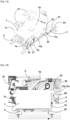
- the invention provides that the box 1 of the loader carries, in its upper part, at least one, and here two parallel protruding tabs 11a, 11b extending in a substantially horizontal plane. These tabs ensure assembly with a right-angled spacer 2 which comes, on the one hand, to bear against the side wall 1a of the box 1 and, on the other hand, to be fixed, by its upper face, under the box C parallel to the two vertical arms 31 connecting the cradle 3 with the box C, as illustrated in particular by the Figure 1B .
- the legs 11a, 11b of the box 1 are each provided with at least one orifice 10 intended to come into contact with a corresponding orifice 20 provided on the spacer 2 for the installation of screws 4 ( Figure 1B ) intended for the vertical assembly of the box 1 with the spacer 2.
- the orifices 20 of the spacer 2 are made in the bottom of one or more cavities 22 intended to receive and wedge the legs 11a, 11b.
- the ends of the spacer 2 are, for their part, provided with lateral orifices 21 for the installation of fixing elements (not shown) under the body C of the vehicle.
- these lateral orifices 21 are provided through bosses 24 extending in a plane located above the upper face 1b of the box 1 and are located on either side of the orifices 20 intended for assembly with the legs 11a, 11b.
- the fixing of the spacer 2 is carried out horizontally and no longer vertically.
- the orifices 20 of the spacer are made through its side wall and receive the tabs 11a, 11b which are here carried opposite each other by the side wall 1a of the box 1. These tabs are, for example, bolted through the holes 20.
- a stop 12 carried by the upper edge of the box 1 ensures the wedging of the spacer 2 upwards.
- the spacer 2 can then be positioned and assembled on the box 1 by being wedged using ears 13.
- the box 1 is fixed to the cradle 3 on the lower edge of its side wall 1c located on the side opposite the face 1a against which the spacer 2 comes to bear while the spacer 2 is provided with feet 23 ensuring the connection with the cradle 3 ( Figure 1B ).
- the fixing method recommended by the invention makes it possible to bring the assembly consisting of the cradle 3 and the charger box 1 as close as possible to the body C and to ensure satisfactory stability even in the presence of vibrations or impacts on the vehicle.
- the support device of the invention allows easy mounting of the charger under the body C of the vehicle. This mounting is carried out by first placing the box 1 containing the charger on the cradle 3, via a lateral access located near the mechanical tooling plate (POM). The following operation consists of positioning and assembling the spacer 2 to the legs 11a, 11b of the box 1, thus closing the lateral access of the cradle 3. The final mounting is completed by vertically installing the screws through the orifices 20 of the spacer 2 into the threads (not shown) provided for this purpose under the body C.
Landscapes
- Engineering & Computer Science (AREA)
- Mechanical Engineering (AREA)
- Chemical & Material Sciences (AREA)
- Combustion & Propulsion (AREA)
- Transportation (AREA)
- Arrangement Or Mounting Of Propulsion Units For Vehicles (AREA)
- Battery Mounting, Suspending (AREA)
Description
- La présente invention revendique la priorité de la demande
française N°2102479 déposée le 12.03.2021 - L'invention s'applique au montage du chargeur de batterie sur la caisse des véhicules automobiles.
- Plus précisément, l'invention concerne un dispositif perfectionné destiné à assurer l'interface entre, respectivement, le chargeur de batterie, son support et la caisse du véhicule.
- Le chargeur de batterie équipant les véhicules automobiles est un composant relativement lourd (une dizaine de kilos) et encombrant qui est logé dans un support fixé sous la caisse du véhicule. Ce support est généralement formé d'un berceau dans lequel est posé le chargeur et qui est pourvu de pattes verticales assurant la liaison avec la caisse.
- Avec les vibrations de la caisse et du fait de l'inertie du chargeur, le support est soumis à des mouvements de balancier. Or, ces sollicitations finissent par entraîner des déformations qui sont susceptibles de provoquer la rupture du support et la chute du chargeur. Par conséquent, les interfaces de support disponibles actuellement ne permettent pas d'avoir une bonne tenue en endurance.
- Le brevet
EP1479567B1 décrit un support destiné à recevoir un équipement électrique à haute tension et à le fixer en suspension sur la structure d'un véhicule automobile. Ce support est évidé pour permettre l'aération de l'équipement à haute tension. - Le brevet
EP2767428B1 décrit un support de chargeur suspendu, pourvu d'un élément de renfort et d'un élément de guidage et permettant de rigidifier l'ensemble constitué du support et du chargeur en position de montage sur la caisse d'un véhicule. - Cependant, aucun de ces documents antérieurs ne divulgue une solution technique permettant d'assurer, à la fois, une rigidification et un calage du support de chargeur sans augmenter l'encombrement et sans faire appel à un élément complémentaire, et un montage du chargeur dans une position située au plus proche de la caisse ou tout au moins à proximité immédiate de la « Platine d'Outillage Mécanique » (dite POM) destinée au montage des divers composants sur le châssis du véhicule.
- Dans ce contexte, l'invention vise à surmonter les problèmes techniques soulevés par les solutions antérieures en proposant un dispositif de support de chargeur perfectionné dans lequel les interfaces d'assemblage avec le chargeur sont rapportées et désormais horizontales et séparées du berceau.
- Cette nouvelle configuration permet de positionner et de monter le support au plus près de la caisse du véhicule avant de poser le chargeur sur le berceau tout en ayant un accès aisé aux éléments d'assemblage entre le support et le chargeur.
- Ce but est atteint, selon l'invention, au moyen d'un dispositif de support du chargeur de batterie pour son montage sous la caisse d'un véhicule automobile, ledit dispositif comprenant un berceau sur lequel repose un caisson renfermant ledit chargeur et au moins deux bras verticaux solidaires du berceau et assurant sa suspension sous la caisse, caractérisé en ce que le caisson porte au moins une patte en saillie assurant l'assemblage avec une entretoise en équerre venant, d'une part, en appui contre la paroi latérale dudit caisson et dont la face supérieure vient, d'autre part, se fixer sous la caisse parallèlement aux bras de liaison verticaux.
- Selon une caractéristique avantageuse, la patte est destinée à venir en regard avec un orifice correspondant ménagé sur l'entretoise pour la pose d'organes destinés à leur assemblage mutuel.
- Le cas échéant, cette patte est pourvue d'au moins un orifice destiné à venir en regard avec un orifice correspondant ménagé sur l'entretoise pour la pose de vis d'assemblage.
- Selon une autre caractéristique avantageuse, les extrémités de l'entretoise sont pourvues d'orifices latéraux pour la pose d'élément de fixation sous la caisse.
- De préférence, les orifices latéraux de cette entretoise sont situés de part et d'autre de l'orifice d'assemblage avec la patte du caisson.
- Selon une variante de réalisation du dispositif de l'invention, les orifices latéraux sont ménagés au travers de bossages s'étendant dans un plan situé au-dessus de la face supérieure du caisson.
- Selon une autre variante, l'entretoise est munie de pieds assurant la liaison avec le berceau.
- Selon un mode de réalisation préférentiel du dispositif de l'invention, le caisson porte deux pattes horizontales parallèles.
- De préférence, le caisson est fixé au berceau sur le bord inférieur de sa paroi latérale située du côté opposé à l'entretoise.
- L'invention prévoit également que l'entretoise comporte au moins une cavité destinée à recevoir et à caler la patte d'assemblage du caisson.
- Un autre objet de l'invention est un véhicule automobile équipé d'un dispositif de support de chargeur de batterie présentant les caractéristiques mentionnées ci-dessus.
- Le dispositif de l'invention consiste donc à modifier la position des interfaces entre le berceau et le chargeur ce qui permet de rigidifier leur liaison, de renforcer l'ensemble et de garantir un montage fiable et stable dans le temps du chargeur sous la caisse, même en présence de vibrations ou de sollicitations importantes (chocs, ...).
- Ainsi, le dispositif de l'invention permet de résoudre le problème mécanique de la faible endurance des solutions techniques antérieures tout en disposant le chargeur au plus près de la caisse et, en particulier, de la platine d'outillage mécanique, sans ajouter de matière et donc sans alourdir le véhicule.
- L'invention permet ainsi avec la même mise en matière, voire même des épaisseurs de tôles moindres, d'avoir un ensemble chargeur / support chargeur plus rigide.
- D'autres caractéristiques et avantages de l'invention ressortiront à la lecture de la description qui va suivre, en référence aux dessins annexés et détaillés ci-après.
- [
Fig. 1A ] est une vue en perspective d'un mode de réalisation préférentiel du dispositif de support de chargeur selon l'invention. - [
Fig. 1B ] est une vue de côté du dispositif de lafigure 1A . - [
Fig. 1C ] est une vue de dessus du dispositif desfigures 1A et 1B . - [
Fig. 2 ] est une vue en perspective d'un autre mode de réalisation du dispositif de support de chargeur selon l'invention. - Pour plus de clarté, les éléments identiques ou similaires sont repérés par des signes de référence identiques dans la description et sur les figures.
- Naturellement, les modes de réalisation du dispositif de l'invention illustrés par les figures présentées ci-dessus et décrites ci-après, ne sont donnés qu'à titre d'exemples non limitatifs. Il est explicitement prévu que l'on puisse proposer et combiner entre eux différents modes pour en proposer d'autres.
- L'invention concerne l'intégration du chargeur de batterie dans la structure d'un véhicule automobile et, plus précisément, le montage du support de ce chargeur sous la caisse du véhicule.
- Le chargeur de batterie équipant les véhicules automobiles est un composant relativement lourd dont la masse représente une dizaine de kilos et qui est logé dans un support fixé sous la caisse du véhicule. Ce support comprend généralement un berceau sur lequel repose un caisson renfermant le chargeur et au moins deux bras verticaux solidaires de ce berceau destinés à assurer la liaison en suspension sous la caisse du véhicule.
- L'invention vise à rigidifier l'ensemble support/chargeur pour éviter les phénomènes préjudiciables de balancier du berceau. A cet effet, et comme illustré par les
figures 1A, 1B et1C , représentant un mode de réalisation préférentiel, l'invention prévoit que le caisson 1 du chargeur porte, dans sa partie supérieure, au moins une, et ici deux pattes parallèles 11a, 11b en saillie s'étendant dans un plan sensiblement horizontal. Ces pattes assurent l'assemblage avec une entretoise 2 en équerre qui vient, d'une part, en appui contre la paroi latérale 1a du caisson 1 et, d'autre part, se fixer, par sa face supérieure, sous la caisse C parallèlement aux deux bras verticaux 31 de liaison du berceau 3 avec la caisse C, comme illustré notamment par lafigure 1B . - Les pattes 11a, 11b du caisson 1 sont pourvues chacune d'au moins un orifice 10 destiné à venir en regard avec un orifice 20 correspondant ménagé sur l'entretoise 2 pour la pose de vis 4 (
figure 1B ) destinées à l'assemblage vertical du caisson 1 avec l'entretoise 2. Les orifices 20 de l'entretoise 2 sont pratiqués dans le fond d'une ou plusieurs cavités 22 destinées à recevoir et à caler les pattes 11a, 11b. - Les extrémités de l'entretoise 2 sont, quant à elles, pourvues d'orifices latéraux 21 pour la pose d'élément de fixation (non représentés) sous la caisse C du véhicule.
- De préférence, ces orifices latéraux 21 sont ménagés au travers de bossages 24 s'étendant dans un plan situé au-dessus de la face supérieure 1b du caisson 1 et sont situés de part et d'autre des orifices 20 destinés à l'assemblage avec les pattes 11a, 11b.
- Dans le mode de réalisation de la
figure 2 , la fixation de l'entretoise 2 est effectuée horizontalement et non plus verticalement. A cet effet, les orifices 20 de l'entretoise sont réalisés au travers de sa paroi latérale et reçoivent les pattes 11a, 11b qui sont ici portées en vis-à-vis par la paroi latérale 1a du caisson 1. Ces pattes sont, par exemple, boulonnées au travers des orifices 20. Une butée 12 portée par le bord supérieur du caisson 1 assure le calage de l'entretoise 2 vers le haut. L'entretoise 2 peut alors être positionnée et assemblée sur le caisson 1 en étant calée grâce à des oreilles 13. - Le caisson 1 est fixé au berceau 3 sur le bord inférieur de sa paroi latérale 1c située du côté opposé à la face 1a contre laquelle l'entretoise 2 vient en appui tandis que l'entretoise 2 est muni de pieds 23 assurant la liaison avec le berceau 3 (
figure 1B ). - Le mode de fixation préconisé par l'invention permet de rapprocher l'ensemble constitué du berceau 3 et du caisson 1 de chargeur au plus près de la caisse C et d'assurer une stabilité satisfaisante même en présence de vibrations ou de chocs sur le véhicule.
En outre, le dispositif de support de l'invention permet d'effectuer un montage aisé du chargeur sous la caisse C du véhicule. Ce montage est effectué en déposant tout d'abord le caisson 1 contenant le chargeur sur le berceau 3, via un accès latéral situé à proximité de la platine d'outillage mécanique (POM). L'opération suivante consiste à positionner et à assembler l'entretoise 2 aux pattes 11a, 11b du caisson 1 en fermant ainsi l'accès latéral du berceau 3. Le montage final est complété par la pose verticale des vis au travers des orifices 20 de l'entretoise 2 jusque dans les taraudages (non représentés) prévus à cet effet sous la caisse C.
Claims (10)
- Dispositif de support du chargeur de batterie pour son montage sous la caisse (C) d'un véhicule automobile, ledit dispositif comprenant un berceau (3) sur lequel repose un caisson (1) renfermant ledit chargeur et au moins deux bras verticaux (31) solidaires du berceau et assurant sa suspension sous la caisse, caractérisé en ce que ledit caisson (1) porte au moins une patte (11a, 11b) en saillie assurant l'assemblage avec une entretoise (2) en équerre venant, d'une part, en appui contre la paroi latérale (1a) dudit caisson (1) et dont la face supérieure vient, d'autre part, se fixer sous la caisse (C) parallèlement aux bras de liaison verticaux (31).
- Dispositif selon la revendication 1, caractérisé en ce que ladite patte (11a, 11b) est destinée à venir en regard avec un orifice (20) correspondant ménagé sur ladite entretoise (2) pour la pose d'organes destinés à leur assemblage mutuel.
- Dispositif selon l'une des revendications précédentes, caractérisé en ce que les extrémités de ladite entretoise (2) sont pourvues d'orifices latéraux (21) pour la pose d'éléments de fixation sous la caisse (C).
- Dispositif selon les revendications 2 et 3, caractérisé en ce que les orifices latéraux (21) de ladite entretoise (2) sont situés de part et d'autre de l'orifice (20) d'assemblage avec la patte (11a, 11b) du caisson (1).
- Dispositif selon la revendication précédente, caractérisé en ce que lesdits orifices latéraux (21) sont ménagés au travers de bossages (24) s'étendant dans un plan situé au-dessus de la face supérieure (1b) du caisson (1).
- Dispositif selon l'une des revendications précédentes, caractérisé en ce que ladite entretoise (2) est munie de pieds (23) assurant la liaison avec le berceau (3).
- Dispositif selon l'une des revendications précédentes, caractérisé en ce que le caisson (1) porte deux pattes (11a, 11b) horizontales et parallèles.
- Dispositif selon l'une des revendications précédentes, caractérisé en ce que ledit caisson (1) est fixé au berceau (3) sur le bord inférieur de sa paroi latérale (1c) située du côté opposé à ladite entretoise (2).
- Dispositif selon l'une des revendications précédentes, caractérisé en ce que ladite entretoise (2) comporte au moins une cavité (22) destinée à recevoir et à caler ladite patte (11a, 11b) d'assemblage du caisson (1).
- Véhicule automobile équipé d'un dispositif de support de chargeur de batterie selon l'une des revendications précédentes.
Applications Claiming Priority (2)
| Application Number | Priority Date | Filing Date | Title |
|---|---|---|---|
| FR2102479A FR3120580B1 (fr) | 2021-03-12 | 2021-03-12 | Dispositif de support du chargeur de batterie des vehicules automobiles |
| PCT/FR2022/050173 WO2022189715A1 (fr) | 2021-03-12 | 2022-02-01 | Dispositif de support du chargeur de batterie des vehicules automobiles |
Publications (2)
| Publication Number | Publication Date |
|---|---|
| EP4304901A1 EP4304901A1 (fr) | 2024-01-17 |
| EP4304901B1 true EP4304901B1 (fr) | 2025-03-26 |
Family
ID=75954021
Family Applications (1)
| Application Number | Title | Priority Date | Filing Date |
|---|---|---|---|
| EP22708584.2A Active EP4304901B1 (fr) | 2021-03-12 | 2022-02-01 | Dispositif de support du chargeur de batterie des vehicules automobiles |
Country Status (4)
| Country | Link |
|---|---|
| EP (1) | EP4304901B1 (fr) |
| CN (1) | CN116981602A (fr) |
| FR (1) | FR3120580B1 (fr) |
| WO (1) | WO2022189715A1 (fr) |
Families Citing this family (3)
| Publication number | Priority date | Publication date | Assignee | Title |
|---|---|---|---|---|
| FR3140851B1 (fr) * | 2022-10-17 | 2025-12-12 | Renault Sas | Agencement pour véhicule comprenant un dispositif de support d’au moins un composant équipant la structure avant du véhicule |
| FR3156072A1 (fr) * | 2023-12-01 | 2025-06-06 | Stellantis Auto Sas | Vehicule automobile comprenant un chargeur a haute tension embarque et un dispositif de protection de connecteurs lateraux dudit chargeur, procede et dispositif sur la base d’un tel vehicule |
| CN119535077B (zh) * | 2025-01-22 | 2025-09-09 | 中汽研新能源汽车检验中心(天津)有限公司 | 车载充电机的电磁兼容测试方法、系统、装置及介质 |
Citations (6)
| Publication number | Priority date | Publication date | Assignee | Title |
|---|---|---|---|---|
| EP1479567A1 (fr) * | 2003-05-21 | 2004-11-24 | HONDA MOTOR CO., Ltd. | Structure pour installer un composant d'équipement haute tension dans un véhicule |
| FR3049920A1 (fr) * | 2016-04-06 | 2017-10-13 | Renault Sas | Agencement de soubassement de vehicule automobile hybride rechargeable. |
| FR3079783A1 (fr) * | 2018-04-05 | 2019-10-11 | Psa Automobiles Sa | Support de systeme de fourniture d’energie electrique sur vehicule hybride ou electrique |
| US20200070670A1 (en) * | 2018-08-31 | 2020-03-05 | Honda Motor Co.,Ltd. | Battery pack and method of manufacturing battery pack |
| FR3086331A1 (fr) * | 2018-09-25 | 2020-03-27 | Psa Automobiles Sa | Suspente d’echappement renforcee, et procede de fabrication de celle-ci |
| EP3783688A1 (fr) * | 2019-01-09 | 2021-02-24 | BYD Company Limited | Bloc-batterie, véhicule et dispositif de stockage d'énergie |
Family Cites Families (3)
| Publication number | Priority date | Publication date | Assignee | Title |
|---|---|---|---|---|
| FR2102479A5 (en) | 1970-08-05 | 1972-04-07 | Comp Generale Electricite | Lithium/lithium iodide cell - with the iodide layer made by chemical attack |
| FR2959604B1 (fr) * | 2010-04-28 | 2012-12-07 | Michelin Soc Tech | Coffre a batterie pour vehicule electrique ou hybride et procede de montage sur le vehicule |
| CN103857548B (zh) | 2011-10-13 | 2017-06-23 | 丰田自动车株式会社 | 蓄电装置的搭载结构 |
-
2021
- 2021-03-12 FR FR2102479A patent/FR3120580B1/fr not_active Expired - Fee Related
-
2022
- 2022-02-01 EP EP22708584.2A patent/EP4304901B1/fr active Active
- 2022-02-01 WO PCT/FR2022/050173 patent/WO2022189715A1/fr not_active Ceased
- 2022-02-01 CN CN202280020802.1A patent/CN116981602A/zh active Pending
Patent Citations (6)
| Publication number | Priority date | Publication date | Assignee | Title |
|---|---|---|---|---|
| EP1479567A1 (fr) * | 2003-05-21 | 2004-11-24 | HONDA MOTOR CO., Ltd. | Structure pour installer un composant d'équipement haute tension dans un véhicule |
| FR3049920A1 (fr) * | 2016-04-06 | 2017-10-13 | Renault Sas | Agencement de soubassement de vehicule automobile hybride rechargeable. |
| FR3079783A1 (fr) * | 2018-04-05 | 2019-10-11 | Psa Automobiles Sa | Support de systeme de fourniture d’energie electrique sur vehicule hybride ou electrique |
| US20200070670A1 (en) * | 2018-08-31 | 2020-03-05 | Honda Motor Co.,Ltd. | Battery pack and method of manufacturing battery pack |
| FR3086331A1 (fr) * | 2018-09-25 | 2020-03-27 | Psa Automobiles Sa | Suspente d’echappement renforcee, et procede de fabrication de celle-ci |
| EP3783688A1 (fr) * | 2019-01-09 | 2021-02-24 | BYD Company Limited | Bloc-batterie, véhicule et dispositif de stockage d'énergie |
Also Published As
| Publication number | Publication date |
|---|---|
| FR3120580B1 (fr) | 2023-02-10 |
| CN116981602A (zh) | 2023-10-31 |
| EP4304901A1 (fr) | 2024-01-17 |
| WO2022189715A1 (fr) | 2022-09-15 |
| FR3120580A1 (fr) | 2022-09-16 |
Similar Documents
| Publication | Publication Date | Title |
|---|---|---|
| EP4304901B1 (fr) | Dispositif de support du chargeur de batterie des vehicules automobiles | |
| EP2200851B1 (fr) | Face avant technique de véhicule automobile | |
| EP2692024B1 (fr) | Dispositif de trappe de prise de charge electrique pour vehicule electrique compatible avec le choc pieton | |
| FR2859676A1 (fr) | Chariot transporteur comportant une ouverture laterale du chassis et une porte rigidifiant le chassis | |
| EP2352673B1 (fr) | Structure rigide de mat d'aeronef plaquee contre une extension laterale de fuselage pour sa fixation | |
| WO2011045497A1 (fr) | Cadre moteur pour moteur electrique de vehicule automobile | |
| EP3423733B1 (fr) | Dispositif d'amortissement de vibrations entre un premier élément vibrant et un deuxième élément | |
| FR2944769A3 (fr) | Plot de fixation pour radiateur de vehicule automobile | |
| FR2974326A1 (fr) | Systeme de connexion pour la fixation d'un dispositif de portage | |
| FR3009542A1 (fr) | Assemblage pour aeronef comprenant un panneau d'acces aux articulations d'un capot de nacelle monte pivotant sur un dispositif d'accrochage de moteur d'aeronef | |
| FR2920739A1 (fr) | Ensemble de carrosserie pour un vehicule et vehicule equipe d'un tel ensemble | |
| EP1255029A1 (fr) | Sous-ensemble de véhicule automobile comportant un vase d'expansion | |
| EP4370406A1 (fr) | Support d'aile avant d'un véhicule automobile | |
| FR3079280A1 (fr) | Dispositif de maintien pour cable ou conduite de fluide dans un vehicule | |
| EP2872718B1 (fr) | Charnière d'articulation d'un ouvrant du type capot de fermeture du compartiment moteur sur une caisse de véhicule automobile | |
| EP1293701B1 (fr) | Support antivibratoire et dispositif antivibratoire comportant un tel support | |
| FR2871943A1 (fr) | Dispositif de positionnement et de fixation d'un boitier de vehicule automobile, notamment d'une batterie, et procede associe | |
| FR3095374A1 (fr) | Liaison a chapes pour la fixation d'une articulation elastique d'un triangle de suspension | |
| FR3060474A1 (fr) | Dispositif de support | |
| FR2766145A1 (fr) | Attache de levage et groupe moto-propulseur equipe d'une telle attache | |
| EP3800692B1 (fr) | Pièce de fixation d'un châssis de permutateur de batterie de chariot élévateur | |
| FR3145839A1 (fr) | Support de calculateur | |
| EP3878025B1 (fr) | Dispositif de support de batterie pour véhicule automobile | |
| FR3102434A1 (fr) | Véhicule automobile comprenant une batterie, et un système de fixation de la batterie | |
| EP4538151A1 (fr) | Agencement pour véhicule automobile comprenant un ensemble de verrouillage d'un capot et un élément de cadre porteur |
Legal Events
| Date | Code | Title | Description |
|---|---|---|---|
| STAA | Information on the status of an ep patent application or granted ep patent |
Free format text: STATUS: UNKNOWN |
|
| STAA | Information on the status of an ep patent application or granted ep patent |
Free format text: STATUS: THE INTERNATIONAL PUBLICATION HAS BEEN MADE |
|
| PUAI | Public reference made under article 153(3) epc to a published international application that has entered the european phase |
Free format text: ORIGINAL CODE: 0009012 |
|
| STAA | Information on the status of an ep patent application or granted ep patent |
Free format text: STATUS: REQUEST FOR EXAMINATION WAS MADE |
|
| 17P | Request for examination filed |
Effective date: 20230724 |
|
| AK | Designated contracting states |
Kind code of ref document: A1 Designated state(s): AL AT BE BG CH CY CZ DE DK EE ES FI FR GB GR HR HU IE IS IT LI LT LU LV MC MK MT NL NO PL PT RO RS SE SI SK SM TR |
|
| DAV | Request for validation of the european patent (deleted) | ||
| DAX | Request for extension of the european patent (deleted) | ||
| GRAP | Despatch of communication of intention to grant a patent |
Free format text: ORIGINAL CODE: EPIDOSNIGR1 |
|
| STAA | Information on the status of an ep patent application or granted ep patent |
Free format text: STATUS: GRANT OF PATENT IS INTENDED |
|
| INTG | Intention to grant announced |
Effective date: 20241029 |
|
| GRAS | Grant fee paid |
Free format text: ORIGINAL CODE: EPIDOSNIGR3 |
|
| GRAA | (expected) grant |
Free format text: ORIGINAL CODE: 0009210 |
|
| STAA | Information on the status of an ep patent application or granted ep patent |
Free format text: STATUS: THE PATENT HAS BEEN GRANTED |
|
| AK | Designated contracting states |
Kind code of ref document: B1 Designated state(s): AL AT BE BG CH CY CZ DE DK EE ES FI FR GB GR HR HU IE IS IT LI LT LU LV MC MK MT NL NO PL PT RO RS SE SI SK SM TR |
|
| REG | Reference to a national code |
Ref country code: GB Ref legal event code: FG4D Free format text: NOT ENGLISH Ref country code: DE Ref legal event code: R084 Ref document number: 602022012260 Country of ref document: DE |
|
| REG | Reference to a national code |
Ref country code: CH Ref legal event code: EP |
|
| REG | Reference to a national code |
Ref country code: DE Ref legal event code: R096 Ref document number: 602022012260 Country of ref document: DE |
|
| REG | Reference to a national code |
Ref country code: IE Ref legal event code: FG4D Free format text: LANGUAGE OF EP DOCUMENT: FRENCH |
|
| PG25 | Lapsed in a contracting state [announced via postgrant information from national office to epo] |
Ref country code: RS Free format text: LAPSE BECAUSE OF FAILURE TO SUBMIT A TRANSLATION OF THE DESCRIPTION OR TO PAY THE FEE WITHIN THE PRESCRIBED TIME-LIMIT Effective date: 20250626 |
|
| PG25 | Lapsed in a contracting state [announced via postgrant information from national office to epo] |
Ref country code: FI Free format text: LAPSE BECAUSE OF FAILURE TO SUBMIT A TRANSLATION OF THE DESCRIPTION OR TO PAY THE FEE WITHIN THE PRESCRIBED TIME-LIMIT Effective date: 20250326 |
|
| REG | Reference to a national code |
Ref country code: LT Ref legal event code: MG9D |
|
| PG25 | Lapsed in a contracting state [announced via postgrant information from national office to epo] |
Ref country code: NO Free format text: LAPSE BECAUSE OF FAILURE TO SUBMIT A TRANSLATION OF THE DESCRIPTION OR TO PAY THE FEE WITHIN THE PRESCRIBED TIME-LIMIT Effective date: 20250626 |
|
| PG25 | Lapsed in a contracting state [announced via postgrant information from national office to epo] |
Ref country code: HR Free format text: LAPSE BECAUSE OF FAILURE TO SUBMIT A TRANSLATION OF THE DESCRIPTION OR TO PAY THE FEE WITHIN THE PRESCRIBED TIME-LIMIT Effective date: 20250326 |
|
| PG25 | Lapsed in a contracting state [announced via postgrant information from national office to epo] |
Ref country code: LV Free format text: LAPSE BECAUSE OF FAILURE TO SUBMIT A TRANSLATION OF THE DESCRIPTION OR TO PAY THE FEE WITHIN THE PRESCRIBED TIME-LIMIT Effective date: 20250326 |
|
| PG25 | Lapsed in a contracting state [announced via postgrant information from national office to epo] |
Ref country code: BG Free format text: LAPSE BECAUSE OF FAILURE TO SUBMIT A TRANSLATION OF THE DESCRIPTION OR TO PAY THE FEE WITHIN THE PRESCRIBED TIME-LIMIT Effective date: 20250326 Ref country code: GR Free format text: LAPSE BECAUSE OF FAILURE TO SUBMIT A TRANSLATION OF THE DESCRIPTION OR TO PAY THE FEE WITHIN THE PRESCRIBED TIME-LIMIT Effective date: 20250627 |
|
| REG | Reference to a national code |
Ref country code: NL Ref legal event code: MP Effective date: 20250326 |
|
| PG25 | Lapsed in a contracting state [announced via postgrant information from national office to epo] |
Ref country code: NL Free format text: LAPSE BECAUSE OF FAILURE TO SUBMIT A TRANSLATION OF THE DESCRIPTION OR TO PAY THE FEE WITHIN THE PRESCRIBED TIME-LIMIT Effective date: 20250326 |
|
| PG25 | Lapsed in a contracting state [announced via postgrant information from national office to epo] |
Ref country code: SE Free format text: LAPSE BECAUSE OF FAILURE TO SUBMIT A TRANSLATION OF THE DESCRIPTION OR TO PAY THE FEE WITHIN THE PRESCRIBED TIME-LIMIT Effective date: 20250326 |
|
| REG | Reference to a national code |
Ref country code: AT Ref legal event code: MK05 Ref document number: 1778768 Country of ref document: AT Kind code of ref document: T Effective date: 20250326 |
|
| PG25 | Lapsed in a contracting state [announced via postgrant information from national office to epo] |
Ref country code: SM Free format text: LAPSE BECAUSE OF FAILURE TO SUBMIT A TRANSLATION OF THE DESCRIPTION OR TO PAY THE FEE WITHIN THE PRESCRIBED TIME-LIMIT Effective date: 20250326 |
|
| PG25 | Lapsed in a contracting state [announced via postgrant information from national office to epo] |
Ref country code: ES Free format text: LAPSE BECAUSE OF FAILURE TO SUBMIT A TRANSLATION OF THE DESCRIPTION OR TO PAY THE FEE WITHIN THE PRESCRIBED TIME-LIMIT Effective date: 20250326 Ref country code: PT Free format text: LAPSE BECAUSE OF FAILURE TO SUBMIT A TRANSLATION OF THE DESCRIPTION OR TO PAY THE FEE WITHIN THE PRESCRIBED TIME-LIMIT Effective date: 20250728 |
|
| PG25 | Lapsed in a contracting state [announced via postgrant information from national office to epo] |
Ref country code: PL Free format text: LAPSE BECAUSE OF FAILURE TO SUBMIT A TRANSLATION OF THE DESCRIPTION OR TO PAY THE FEE WITHIN THE PRESCRIBED TIME-LIMIT Effective date: 20250326 Ref country code: IT Free format text: LAPSE BECAUSE OF FAILURE TO SUBMIT A TRANSLATION OF THE DESCRIPTION OR TO PAY THE FEE WITHIN THE PRESCRIBED TIME-LIMIT Effective date: 20250326 |
|
| PG25 | Lapsed in a contracting state [announced via postgrant information from national office to epo] |
Ref country code: AT Free format text: LAPSE BECAUSE OF FAILURE TO SUBMIT A TRANSLATION OF THE DESCRIPTION OR TO PAY THE FEE WITHIN THE PRESCRIBED TIME-LIMIT Effective date: 20250326 |
|
| PG25 | Lapsed in a contracting state [announced via postgrant information from national office to epo] |
Ref country code: EE Free format text: LAPSE BECAUSE OF FAILURE TO SUBMIT A TRANSLATION OF THE DESCRIPTION OR TO PAY THE FEE WITHIN THE PRESCRIBED TIME-LIMIT Effective date: 20250326 |
|
| PG25 | Lapsed in a contracting state [announced via postgrant information from national office to epo] |
Ref country code: RO Free format text: LAPSE BECAUSE OF FAILURE TO SUBMIT A TRANSLATION OF THE DESCRIPTION OR TO PAY THE FEE WITHIN THE PRESCRIBED TIME-LIMIT Effective date: 20250326 |
|
| PG25 | Lapsed in a contracting state [announced via postgrant information from national office to epo] |
Ref country code: SK Free format text: LAPSE BECAUSE OF FAILURE TO SUBMIT A TRANSLATION OF THE DESCRIPTION OR TO PAY THE FEE WITHIN THE PRESCRIBED TIME-LIMIT Effective date: 20250326 |
|
| PG25 | Lapsed in a contracting state [announced via postgrant information from national office to epo] |
Ref country code: IS Free format text: LAPSE BECAUSE OF FAILURE TO SUBMIT A TRANSLATION OF THE DESCRIPTION OR TO PAY THE FEE WITHIN THE PRESCRIBED TIME-LIMIT Effective date: 20250726 |
|
| REG | Reference to a national code |
Ref country code: DE Ref legal event code: R097 Ref document number: 602022012260 Country of ref document: DE |
|
| PG25 | Lapsed in a contracting state [announced via postgrant information from national office to epo] |
Ref country code: DK Free format text: LAPSE BECAUSE OF FAILURE TO SUBMIT A TRANSLATION OF THE DESCRIPTION OR TO PAY THE FEE WITHIN THE PRESCRIBED TIME-LIMIT Effective date: 20250326 |
|
| PG25 | Lapsed in a contracting state [announced via postgrant information from national office to epo] |
Ref country code: CZ Free format text: LAPSE BECAUSE OF FAILURE TO SUBMIT A TRANSLATION OF THE DESCRIPTION OR TO PAY THE FEE WITHIN THE PRESCRIBED TIME-LIMIT Effective date: 20250326 |
|
| PLBE | No opposition filed within time limit |
Free format text: ORIGINAL CODE: 0009261 |
|
| STAA | Information on the status of an ep patent application or granted ep patent |
Free format text: STATUS: NO OPPOSITION FILED WITHIN TIME LIMIT |
|
| REG | Reference to a national code |
Ref country code: CH Ref legal event code: L10 Free format text: ST27 STATUS EVENT CODE: U-0-0-L10-L00 (AS PROVIDED BY THE NATIONAL OFFICE) Effective date: 20260211 |
|
| 26N | No opposition filed |
Effective date: 20260105 |
|
| PGFP | Annual fee paid to national office [announced via postgrant information from national office to epo] |
Ref country code: DE Payment date: 20260121 Year of fee payment: 5 |
|
| PGFP | Annual fee paid to national office [announced via postgrant information from national office to epo] |
Ref country code: FR Payment date: 20260121 Year of fee payment: 5 |