EP4303962A1 - Fluoride ion battery and method for producing fluoride ion battery - Google Patents
Fluoride ion battery and method for producing fluoride ion battery Download PDFInfo
- Publication number
- EP4303962A1 EP4303962A1 EP23172510.2A EP23172510A EP4303962A1 EP 4303962 A1 EP4303962 A1 EP 4303962A1 EP 23172510 A EP23172510 A EP 23172510A EP 4303962 A1 EP4303962 A1 EP 4303962A1
- Authority
- EP
- European Patent Office
- Prior art keywords
- ion battery
- fluoride ion
- negative electrode
- active material
- electrode active
- Prior art date
- Legal status (The legal status is an assumption and is not a legal conclusion. Google has not performed a legal analysis and makes no representation as to the accuracy of the status listed.)
- Granted
Links
Images


Classifications
-
- H—ELECTRICITY
- H01—ELECTRIC ELEMENTS
- H01M—PROCESSES OR MEANS, e.g. BATTERIES, FOR THE DIRECT CONVERSION OF CHEMICAL ENERGY INTO ELECTRICAL ENERGY
- H01M4/00—Electrodes
- H01M4/02—Electrodes composed of, or comprising, active material
- H01M4/36—Selection of substances as active materials, active masses, active liquids
- H01M4/58—Selection of substances as active materials, active masses, active liquids of inorganic compounds other than oxides or hydroxides, e.g. sulfides, selenides, tellurides, halogenides or LiCoFy; of polyanionic structures, e.g. phosphates, silicates or borates
- H01M4/582—Halogenides
-
- H—ELECTRICITY
- H01—ELECTRIC ELEMENTS
- H01M—PROCESSES OR MEANS, e.g. BATTERIES, FOR THE DIRECT CONVERSION OF CHEMICAL ENERGY INTO ELECTRICAL ENERGY
- H01M4/00—Electrodes
- H01M4/02—Electrodes composed of, or comprising, active material
- H01M4/36—Selection of substances as active materials, active masses, active liquids
- H01M4/58—Selection of substances as active materials, active masses, active liquids of inorganic compounds other than oxides or hydroxides, e.g. sulfides, selenides, tellurides, halogenides or LiCoFy; of polyanionic structures, e.g. phosphates, silicates or borates
-
- H—ELECTRICITY
- H01—ELECTRIC ELEMENTS
- H01M—PROCESSES OR MEANS, e.g. BATTERIES, FOR THE DIRECT CONVERSION OF CHEMICAL ENERGY INTO ELECTRICAL ENERGY
- H01M4/00—Electrodes
- H01M4/02—Electrodes composed of, or comprising, active material
- H01M4/36—Selection of substances as active materials, active masses, active liquids
- H01M4/58—Selection of substances as active materials, active masses, active liquids of inorganic compounds other than oxides or hydroxides, e.g. sulfides, selenides, tellurides, halogenides or LiCoFy; of polyanionic structures, e.g. phosphates, silicates or borates
- H01M4/583—Carbonaceous material, e.g. graphite-intercalation compounds or CFx
-
- H—ELECTRICITY
- H01—ELECTRIC ELEMENTS
- H01M—PROCESSES OR MEANS, e.g. BATTERIES, FOR THE DIRECT CONVERSION OF CHEMICAL ENERGY INTO ELECTRICAL ENERGY
- H01M10/00—Secondary cells; Manufacture thereof
- H01M10/05—Accumulators with non-aqueous electrolyte
-
- H—ELECTRICITY
- H01—ELECTRIC ELEMENTS
- H01M—PROCESSES OR MEANS, e.g. BATTERIES, FOR THE DIRECT CONVERSION OF CHEMICAL ENERGY INTO ELECTRICAL ENERGY
- H01M10/00—Secondary cells; Manufacture thereof
- H01M10/05—Accumulators with non-aqueous electrolyte
- H01M10/056—Accumulators with non-aqueous electrolyte characterised by the materials used as electrolytes, e.g. mixed inorganic/organic electrolytes
- H01M10/0561—Accumulators with non-aqueous electrolyte characterised by the materials used as electrolytes, e.g. mixed inorganic/organic electrolytes the electrolyte being constituted of inorganic materials only
- H01M10/0562—Solid materials
-
- H—ELECTRICITY
- H01—ELECTRIC ELEMENTS
- H01M—PROCESSES OR MEANS, e.g. BATTERIES, FOR THE DIRECT CONVERSION OF CHEMICAL ENERGY INTO ELECTRICAL ENERGY
- H01M10/00—Secondary cells; Manufacture thereof
- H01M10/05—Accumulators with non-aqueous electrolyte
- H01M10/058—Construction or manufacture
-
- H—ELECTRICITY
- H01—ELECTRIC ELEMENTS
- H01M—PROCESSES OR MEANS, e.g. BATTERIES, FOR THE DIRECT CONVERSION OF CHEMICAL ENERGY INTO ELECTRICAL ENERGY
- H01M10/00—Secondary cells; Manufacture thereof
- H01M10/42—Methods or arrangements for servicing or maintenance of secondary cells or secondary half-cells
- H01M10/44—Methods for charging or discharging
-
- H—ELECTRICITY
- H01—ELECTRIC ELEMENTS
- H01M—PROCESSES OR MEANS, e.g. BATTERIES, FOR THE DIRECT CONVERSION OF CHEMICAL ENERGY INTO ELECTRICAL ENERGY
- H01M4/00—Electrodes
- H01M4/02—Electrodes composed of, or comprising, active material
- H01M4/36—Selection of substances as active materials, active masses, active liquids
- H01M4/38—Selection of substances as active materials, active masses, active liquids of elements or alloys
-
- H—ELECTRICITY
- H01—ELECTRIC ELEMENTS
- H01M—PROCESSES OR MEANS, e.g. BATTERIES, FOR THE DIRECT CONVERSION OF CHEMICAL ENERGY INTO ELECTRICAL ENERGY
- H01M4/00—Electrodes
- H01M4/02—Electrodes composed of, or comprising, active material
- H01M4/62—Selection of inactive substances as ingredients for active masses, e.g. binders, fillers
-
- H—ELECTRICITY
- H01—ELECTRIC ELEMENTS
- H01M—PROCESSES OR MEANS, e.g. BATTERIES, FOR THE DIRECT CONVERSION OF CHEMICAL ENERGY INTO ELECTRICAL ENERGY
- H01M4/00—Electrodes
- H01M4/02—Electrodes composed of, or comprising, active material
- H01M2004/026—Electrodes composed of, or comprising, active material characterised by the polarity
- H01M2004/027—Negative electrodes
-
- H—ELECTRICITY
- H01—ELECTRIC ELEMENTS
- H01M—PROCESSES OR MEANS, e.g. BATTERIES, FOR THE DIRECT CONVERSION OF CHEMICAL ENERGY INTO ELECTRICAL ENERGY
- H01M2300/00—Electrolytes
- H01M2300/0017—Non-aqueous electrolytes
- H01M2300/0065—Solid electrolytes
- H01M2300/0068—Solid electrolytes inorganic
- H01M2300/008—Halides
-
- Y—GENERAL TAGGING OF NEW TECHNOLOGICAL DEVELOPMENTS; GENERAL TAGGING OF CROSS-SECTIONAL TECHNOLOGIES SPANNING OVER SEVERAL SECTIONS OF THE IPC; TECHNICAL SUBJECTS COVERED BY FORMER USPC CROSS-REFERENCE ART COLLECTIONS [XRACs] AND DIGESTS
- Y02—TECHNOLOGIES OR APPLICATIONS FOR MITIGATION OR ADAPTATION AGAINST CLIMATE CHANGE
- Y02E—REDUCTION OF GREENHOUSE GAS [GHG] EMISSIONS, RELATED TO ENERGY GENERATION, TRANSMISSION OR DISTRIBUTION
- Y02E60/00—Enabling technologies; Technologies with a potential or indirect contribution to GHG emissions mitigation
- Y02E60/10—Energy storage using batteries
-
- Y—GENERAL TAGGING OF NEW TECHNOLOGICAL DEVELOPMENTS; GENERAL TAGGING OF CROSS-SECTIONAL TECHNOLOGIES SPANNING OVER SEVERAL SECTIONS OF THE IPC; TECHNICAL SUBJECTS COVERED BY FORMER USPC CROSS-REFERENCE ART COLLECTIONS [XRACs] AND DIGESTS
- Y02—TECHNOLOGIES OR APPLICATIONS FOR MITIGATION OR ADAPTATION AGAINST CLIMATE CHANGE
- Y02P—CLIMATE CHANGE MITIGATION TECHNOLOGIES IN THE PRODUCTION OR PROCESSING OF GOODS
- Y02P70/00—Climate change mitigation technologies in the production process for final industrial or consumer products
- Y02P70/50—Manufacturing or production processes characterised by the final manufactured product
Definitions
- the present disclosure relates to a fluoride ion battery and to a method for producing the fluoride ion battery.
- PTL 1 discloses a fluoride ion battery comprising a positive electrode active material layer, a negative electrode active material layer, and an electrolyte layer formed between the positive electrode active material layer and negative electrode active material layer, wherein the negative electrode active material layer comprises a negative electrode active material including Si element and La element and the solid electrolyte includes La element, Ba element and F element.
- the object of the present disclosure is to provide a fluoride ion battery comprising a negative electrode active material that can exhibit high charge-discharge capacity, as well as a method for producing it.
- the fluoride ion battery according to aspect 1 or 2 which has a lanthanoid fluoride as the solid electrolyte.
- a method for producing a fluoride ion battery which includes discharge of a fluoride ion battery precursor having La x C( 1.00-x ) as the negative electrode active material, where 0.00 ⁇ x ⁇ 1.00, until the upper limit potential of the negative electrode reaches 2.5 to 3.5 V vs Pb/PbF 2 .
- a fluoride ion battery comprising a negative electrode active material that can exhibit high charge-discharge capacity, as well as a method for producing it.
- a fluoride ion battery of the disclosure has La x C( 1.00-x ) as the negative electrode active material, where 0.00 ⁇ x ⁇ 1.00.
- the La x C( 1.00-x ) as the negative electrode active material of the fluoride ion battery of the disclosure has a higher charge-discharge capacity than lanthanum alone.
- La x C( 1.00-x ) as the negative electrode active material allows oxidation-reduction reaction at a more electropositive potential than lanthanum alone.
- the negative electrode is to contain a solid electrolyte, oxidation-reduction reaction at a more electropositive potential than the active material can widen the selection range for the type of solid electrolyte.
- the charge-discharge capacity of the fluoride ion battery of the disclosure may be 300 mAh/g or greater.
- a fluoride ion battery having La x C( 1.00-x ) as the negative electrode active material and a charge-discharge capacity of 300 mAh/g or greater can be produced by the production method of the disclosure, for example.
- Fig. 1 is a schematic diagram showing a fluoride ion battery 1 according to a first embodiment of the disclosure.
- the fluoride ion battery 1 of the first embodiment of the disclosure has a structure with a positive electrode collector layer 10, a positive electrode active material layer 20, an electrolyte layer 30, a negative electrode active material layer 40 and a negative electrode collector layer 50 stacked in that order.
- the negative electrode active material layer 40 has La x C( 1.00-x ) as the negative electrode active material.
- the fluoride ion battery of the disclosure may be a liquid battery or solid-state battery, and is most preferably an all-solid-state battery.
- the fluoride ion battery of the disclosure may be either a primary battery or a secondary battery.
- Examples of types for the fluoride ion battery of the disclosure include coin types, laminated types, cylindrical types and rectilinear types.
- a fluoride ion battery of the disclosure has La x C( 1.00-x ) as the negative electrode active material, where 0.00 ⁇ x ⁇ 1.00.
- the negative electrode active material of a fluoride ion battery releases fluorine during charge and absorbs fluorine during discharge.
- the negative electrode active material in the fluoride ion battery of the disclosure is La x C( 1.00-x ) in the fully defluoridated state, but may include F depending on the charge-discharge state of the fluoride ion battery.
- La x C( 1.00-x ) exhibits an especially high charge-discharge capacity when x is 0.30 to 0.45. This is due to a larger metal carbide portion of the La x C( 1.00-x ) particles when x is in this range.
- x is less than 0.30 or greater than 0.45, the proportion of simple carbon or simple lanthanum in the crystals increases. The property more closely resembles simple La as x approaches 1.00.
- the value of x may be 0.30 or greater, 0.31 or greater, 0.32 or greater or 0.33 or greater, and 0.45 or smaller, 0.43 or smaller, 0.41 or smaller, 0.40 or smaller.
- the negative electrode active material may be in a particulate form, for example.
- the mean particle diameter (D50) of the negative electrode active material may be 0.01 up to 50 ⁇ m, for example.
- the mean particle diameter (D50) of the negative electrode active material may be 0.01 ⁇ m or greater, 0.05 ⁇ m or greater or 0.10 ⁇ m or greater, and 50 ⁇ m or smaller, 25 ⁇ m or smaller or 10 ⁇ m or smaller.
- the mean particle diameter (D50) of the negative electrode active material can be determined from the results of particle size distribution measurement by laser diffraction scattering, for example.
- the method of producing the negative electrode active material may be an arc melting method using La and C as starting materials, for example, but there is no limitation to this method.
- the fluoride ion battery of the disclosure may comprise a solid electrolyte.
- the solid electrolyte may be any solid electrolyte that can be used in a fluoride ion battery.
- solid electrolytes examples include fluorides of lanthanoid elements such as La and Ce, fluorides of alkali metal elements such as Li, Na, K, Rb and Cs, and fluorides of alkaline earth elements such as Ca, Sr and Ba.
- the solid electrolyte may also be a fluoride comprising multiple elements from among lanthanoid elements, alkali metal elements and alkaline earth elements.
- solid electrolytes include La (1-x) Ba x F (3-x) (0 ⁇ x ⁇ 1), Pb (2-x) Sn x F 4 (0 ⁇ x ⁇ 2), Ca (2-x) Ba x F 4 (0 ⁇ x ⁇ 2) and Ce (1-x) BaxF (3-x) (0 ⁇ x ⁇ 1).
- the symbol "x” in each formula may be larger than zero, such as 0.3 or greater, 0.5 or greater or 0.9 or greater.
- the symbol “x” may also represent a value smaller than 1, such as 0.9 or smaller, 0.5 or smaller or 0.3 or smaller.
- the "x" in the specific example of a solid electrolyte is of course distinct from the "x" in La x C( 1.00-x ) for the negative electrode active material of the disclosure, the two being mutually independent values.
- the form of the solid electrolyte is not particularly restricted, and may be particulate, for example.
- the fluoride ion battery of the disclosure is especially useful for when a lanthanoid fluoride, i.e. a fluoride of a lanthanoid element, is used as the solid electrolyte.
- a lanthanoid fluoride has relatively high fluoride ion conductivity while undergoing reductive decomposition at about the same potential as lanthanum, to deposit metallic lanthanum. Therefore, when a lanthanoid fluoride is also used as a solid electrolyte in a fluoride ion battery using metallic lanthanum as the negative electrode active material, the ion conduction paths tend to be blocked.
- the negative electrode active material in the fluoride ion battery of the disclosure is La x C (1.00-x) which exhibits oxidation-reduction reaction at a more electropositive potential than metallic lanthanum, it is possible to inhibit reductive decomposition of lanthanoid fluorides when the battery is in use.
- the lanthanoid fluoride used as the solid electrolyte may be present in the positive electrode active material layer, electrolyte layer and/or negative electrode active material layer, but most preferably it is present in the negative electrode active material layer.
- the fluoride ion battery of the disclosure may also have a positive electrode collector layer, positive electrode active material layer, electrolyte layer, negative electrode active material layer and negative electrode collector layer, for example.
- the fluoride ion battery of the disclosure may also have a battery case housing the constituent elements.
- Examples of materials for the positive electrode collector layer include stainless steel (SUS), aluminum, nickel, iron, titanium, platinum and carbon.
- the form of the positive electrode collector layer may be a foil, mesh or porous form.
- the positive electrode active material layer of the disclosure comprises a positive electrode active material, and optionally a solid electrolyte, a conductive aid and a binder.
- the positive electrode active material of the disclosure is an active material that is usually defluoridated during discharge.
- positive electrode active materials include simple metals, alloys and metal oxides, as well as their fluorides.
- metal elements to be included in the positive electrode active material include Cu, Ag, Ni, Co, Pb, Ce, Mn, Au, Pt, Rh, V, Os, Ru, Fe, Cr, Bi, Nb, Sb, Ti, Sn and Zn.
- the positive electrode active material is preferably FeF 3 , CuF 2 , BiF 3 or AgF.
- the content of the positive electrode active material in the positive electrode active material layer is preferably higher from the viewpoint of capacity.
- the mass ratio of the positive electrode active material with respect to the mass of the positive electrode active material layer may be 10 to 90 mass%, and is preferably 20 to 80 mass%.
- the solid electrolyte used may be any one mentioned above under ⁇ Solid electrolyte>.
- the conductive aid is not particularly restricted so long as it has the desired electron conductivity, and examples include carbon materials.
- carbon materials include carbon blacks such as acetylene black, Ketchen black, furnace black and thermal black, and carbon nanotubes.
- the mass ratio of the conductive aid with respect to the mass of the positive electrode active material layer may be 1 to 70 mass%, and is preferably 5 to 40 mass%.
- the binder is not particularly restricted so long as it is chemically and electrically stable, and examples include fluorine-based binders such as polyvinylidene fluoride (PVDF) and polytetrafluoroethylene (PTFE).
- PVDF polyvinylidene fluoride
- PTFE polytetrafluoroethylene
- the thickness of the positive electrode layer is not particularly restricted and will differ significantly depending on the battery construction.
- the electrolyte layer may be composed of an electrolyte solution and optionally a separator, for example.
- the electrolyte solution may comprise a fluoride salt and an organic solvent, for example.
- fluoride salts include inorganic fluoride salts, organic fluoride salts and ionic liquids.
- inorganic fluoride salts include XF (where X is Li, Na, K, Rb or Cs).
- cations in organic fluoride salts include alkylammonium cations such as tetramethylammonium cation.
- the concentration of the fluoride salt in the electrolyte solution may be 0.1 mol% or greater and 40 mol% or lower, for example, and is preferably 1 mol% to 10 mol%.
- the organic solvent of the electrolyte solution will usually be a solvent that dissolves the fluoride salt.
- organic solvents include glymes such as triethyleneglycol dimethyl ether (G3) and tetraethyleneglycol dimethyl ether (G4), cyclic carbonates such as ethylene carbonate (EC), fluoroethylene carbonate (FEC), difluoroethylene carbonate (DFEC), propylene carbonate (PC) and butylene carbonate (BC), and linear carbonates such as dimethyl carbonate (DMC), diethyl carbonate (DEC) and ethylmethyl carbonate (EMC).
- G3 triethyleneglycol dimethyl ether
- G4 tetraethyleneglycol dimethyl ether
- cyclic carbonates such as ethylene carbonate (EC), fluoroethylene carbonate (FEC), difluoroethylene carbonate (DFEC), propylene carbonate (PC) and butylene carbonate (BC)
- linear carbonates such as dimethyl carbonate (DMC), die
- the separator is not particularly restricted so long as it has a composition that can withstand the range of use of the fluoride ion battery.
- Examples for the separator include polymer nonwoven fabrics such as polypropylene nonwoven fabrics and polyphenylene sulfide nonwoven fabrics, and microporous films of olefin-based resins such as polyethylene and polypropylene.
- the electrolyte layer may be a solid electrolyte layer, for example.
- the solid electrolyte used may be any one mentioned above under ⁇ Solid electrolyte>.
- the negative electrode active material layer of the disclosure comprises a negative electrode active material, and optionally a solid electrolyte, a conductive aid and a binder.
- a negative electrode active material layer comprises at least La x C( 1.00-x ) as the negative electrode active material.
- the content of the negative electrode active material in the negative electrode active material layer is preferably higher from the viewpoint of capacity.
- the mass ratio of the negative electrode active material with respect to the mass of the negative electrode active material layer may be 10 to 90 mass%, and is preferably 20 to 80 mass%.
- the solid electrolyte, conductive aid and binder used may be any of those mentioned above under "(Positive electrode active material layer)".
- Examples of materials for the negative electrode collector layer include stainless steel (SUS), copper, nickel, iron, titanium, platinum and carbon.
- the form of the negative electrode collector layer may be a foil, mesh or porous form.
- the battery case may be in any form that is able to house the members of a fluoride ion battery, and any battery case commonly employed for batteries may be used.
- the method for producing a fluoride ion battery of the disclosure includes discharging a fluoride ion battery precursor having La x C( 1.00-x ) as the negative electrode active material, where 0.00 ⁇ x ⁇ 1.00, until the upper limit potential of the negative electrode reaches 2.5 V to 3.5 V vs Pb/PbF 2 .
- the charge-discharge capacity can be further increased by discharging the fluoride ion battery precursor comprising La x C (1.00-x) , until the upper limit potential of the negative electrode reaches 2.5 V to 3.5 V vs Pb/PbF 2 .
- the La x C( 1.00-x ) in the fluoride ion battery precursor may be synthesized by an arc melting method using La and C as starting materials, for example, with optional pulverizing.
- the upper limit potential of the negative electrode for discharge of the fluoride ion battery precursor may be 2.5 V vs Pb/PbF 2 or greater, 2.6 V vs Pb/PbF 2 or greater, 2.7 V vs Pb/PbF 2 or greater or 2.8 V vs Pb/PbF 2 or greater, and 3.5 V vs Pb/PbF 2 or lower, 3.4 V vs Pb/PbF 2 or lower, 3.3 V vs Pb/PbF 2 or lower or 3.2 V vs Pb/PbF 2 or lower.
- the method for producing a fluoride ion battery of the disclosure preferably includes charge-discharge so that the upper limit potential of the negative electrode is -0.5 V to 0.5 V vs Pb/PbF 2 , and the lower limit potential of the negative electrode is -3.0 V to -2.0 V vs Pb/PbF 2 , before discharge until the upper limit potential of the negative electrode reaches 2.5 V to 3.5 V vs Pb/PbF 2 .
- the upper limit potential of the negative electrode for charge-discharge before discharge until the upper limit potential of the negative electrode reaches 2.5 V to 3.5 V vs Pb/PbF 2 may be -0.5 V vs Pb/PbF 2 or greater, -0.4 V vs Pb/PbF 2 or greater, -0.3 V vs Pb/PbF 2 or greater or - 0.2 V vs Pb/PbF 2 or greater, and 0.5 V vs Pb/PbF 2 or lower, 0.4 V vs Pb/PbF 2 or lower, 0.3 V vs Pb/PbF 2 or lower or 0.0 V vs Pb/PbF 2 or lower.
- the lower limit potential of the negative electrode for charge-discharge before discharge until the upper limit potential of the negative electrode reaches 2.5 V to 3.5 V vs Pb/PbF 2 may be -3.0 V vs Pb/PbF 2 or greater, -2.9 V vs Pb/PbF 2 or greater, -2.7 V vs Pb/PbF 2 or greater or - 2.5 V vs Pb/PbF 2 or greater, and -2.0 V vs Pb/PbF 2 or lower, -2.2 V vs Pb/PbF 2 or lower, -2.3 V vs Pb/PbF 2 or lower or -2.4 V vs Pb/PbF 2 or lower.
- CaF 2 and BaF 2 were then mixed for 20 hours with a ball mill at 600 rpm, to synthesize Ca 0.5 Ba 0.5 F 2 as a solid electrolyte.
- the synthesized La 0.33 C 0.67 was pulverized to 100 ⁇ m or smaller with a mortar, and then the La 0.33 C 0.67 and Ca 0.5 Ba 0.5 F 2 were mixed together with vapor-grown carbon fiber (VGCF) as a conductive aid to a weight ratio of 3:6: 1, for 10 hours using a ball mill at 200 rpm, to prepare a negative electrode mixture.
- VGCF vapor-grown carbon fiber
- PbF 2 as a positive electrode active material and acetylene black as a conductive aid were weighed out to a weight ratio of 95:5, and mixed for 3 hours with a ball mill at 600 rpm.
- the negative electrode active material used in the fluoride ion battery of Example 2 was La 0.40 C 0.60 .
- a fluoride ion battery for Reference Example 1 was fabricated in the same manner as Example 1, except that La was used as the negative electrode active material.
- the fluoride ion batteries of Examples 1 and 2 and Reference Example 1 were subjected to constant current charge-discharge for 3 cycles at 200°C with a current of 50 ⁇ A, until the upper limit potential of the negative electrode reached 0.00 V vs Pb/PbF 2 and the lower limit potential of the negative electrode reached -2.5 V vs Pb/PbF 2 .
- Fig. 2 is a graph showing the charge-discharge characteristic for the fluoride ion battery of Example 1.
- Fig. 3 is a graph showing the charge-discharge characteristic for the fluoride ion battery of Example 2.
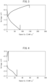
- Fig. 4 is a graph showing the charge-discharge characteristic for the fluoride ion battery of Reference Example 1.
- the fluoride ion battery of Example 1 which used La 0.33 C 0.67 as the negative electrode active material and the fluoride ion battery of Example 2 which used La 0.40 C 0.60 as the negative electrode active material exhibited higher charge-discharge capacity than the fluoride ion battery of Reference Example 1 which used La as the negative electrode active material.
- the charge-discharge tested fluoride ion battery of Example 1 was charged until the upper limit potential of the negative electrode reached 3.00 V vs Pb/PbF 2 , and was used as a fluoride ion battery for Example 3.
- Example 2 the charge-discharge tested fluoride ion battery of Example 2 was charged until the upper limit potential of the negative electrode reached 3.00 V vs Pb/PbF 2 , and was used as a fluoride ion battery for Example 4.
- the fluoride ion batteries of Examples 3 and 4 were subjected to charge-discharge testing.
- the charge-discharge curve of the fluoride ion battery of Example 3 is shown in Fig. 5 .
- the charge-discharge curve of the fluoride ion battery of Example 4 is shown in Fig. 6 .
- the fluoride ion batteries of Examples 3 and 4 that were charged until the upper limit potential of the negative electrode reached 3.00 V vs Pb/PbF 2 exhibited charge-discharge capacities of 300 mAh/g or greater, which were higher charge-discharge capacities than the fluoride ion batteries of Examples 1 and 2 that were not charged until the upper limit potential of the negative electrode reached 3.00 V vs Pb/PbF 2 .
Landscapes
- Chemical & Material Sciences (AREA)
- Chemical Kinetics & Catalysis (AREA)
- Electrochemistry (AREA)
- General Chemical & Material Sciences (AREA)
- Inorganic Chemistry (AREA)
- Engineering & Computer Science (AREA)
- Manufacturing & Machinery (AREA)
- Physics & Mathematics (AREA)
- Condensed Matter Physics & Semiconductors (AREA)
- General Physics & Mathematics (AREA)
- Secondary Cells (AREA)
- Battery Electrode And Active Subsutance (AREA)
Abstract
Description
- The present disclosure relates to a fluoride ion battery and to a method for producing the fluoride ion battery.
-
PTL 1 discloses a fluoride ion battery comprising a positive electrode active material layer, a negative electrode active material layer, and an electrolyte layer formed between the positive electrode active material layer and negative electrode active material layer, wherein the negative electrode active material layer comprises a negative electrode active material including Si element and La element and the solid electrolyte includes La element, Ba element and F element. - [PTL 1]
Japanese Unexamined Patent Publication No. 2020-191252 - It is desirable for a fluoride ion battery to have high charge-discharge capacity.
- The object of the present disclosure is to provide a fluoride ion battery comprising a negative electrode active material that can exhibit high charge-discharge capacity, as well as a method for producing it.
- The present inventors have found that the aforementioned object can be achieved by the means described below.
- A fluoride ion battery having LaxC(1.00-x) as the negative electrode active material, where 0.00 < x < 1.00.
- The fluoride ion battery according to
aspect 1, where 0.30 ≤ x ≤ 0.45. - The fluoride ion battery according to
aspect 1 or 2, which has a lanthanoid fluoride as the solid electrolyte. - The fluoride ion battery according to any one of
aspects 1 to 3, wherein the charge-discharge capacity is 300 mAh/g or greater. - A method for producing a fluoride ion battery, which includes discharge of a fluoride ion battery precursor having LaxC(1.00-x) as the negative electrode active material, where 0.00 < x < 1.00, until the upper limit potential of the negative electrode reaches 2.5 to 3.5 V vs Pb/PbF2.
- The method for producing a fluoride ion battery according to aspect 5, which includes charge-discharge so that the upper limit potential of the negative electrode is -0.5 V to 0.5 V vs Pb/PbF2, and the lower limit potential of the negative electrode is -3.0 V to -2.0 V vs Pb/PbF2, before discharge until the upper limit potential of the negative electrode reaches 2.5 V to 3.5 V vs Pb/PbF2.
- According to the disclosure it is possible to provide a fluoride ion battery comprising a negative electrode active material that can exhibit high charge-discharge capacity, as well as a method for producing it.
-
-
Fig. 1 is a schematic diagram showing a fluoride ion battery according to a first embodiment of the disclosure. -
Fig. 2 is a graph showing the charge-discharge characteristic for the fluoride ion battery of Example 1. -
Fig. 3 is a graph showing the charge-discharge characteristic for the fluoride ion battery of Example 2. -
Fig. 4 is a graph showing the charge-discharge characteristic for the fluoride ion battery of Reference Example 1. -
Fig. 5 is a graph showing the charge-discharge characteristic for the fluoride ion battery of Example 3. -
Fig. 6 is a graph showing the charge-discharge characteristic for the fluoride ion battery of Example 4. - Embodiments of the disclosure will now be described in detail. The disclosure is not limited to the embodiments described below, however, and various modifications may be implemented which do not depart from the gist thereof.
- A fluoride ion battery of the disclosure has LaxC(1.00-x) as the negative electrode active material, where 0.00 < x < 1.00.
- The LaxC(1.00-x) as the negative electrode active material of the fluoride ion battery of the disclosure has a higher charge-discharge capacity than lanthanum alone.
- Using LaxC(1.00-x) as the negative electrode active material allows oxidation-reduction reaction at a more electropositive potential than lanthanum alone. When the negative electrode is to contain a solid electrolyte, oxidation-reduction reaction at a more electropositive potential than the active material can widen the selection range for the type of solid electrolyte.
- The charge-discharge capacity of the fluoride ion battery of the disclosure may be 300 mAh/g or greater. A fluoride ion battery having LaxC(1.00-x) as the negative electrode active material and a charge-discharge capacity of 300 mAh/g or greater can be produced by the production method of the disclosure, for example.
-
Fig. 1 is a schematic diagram showing afluoride ion battery 1 according to a first embodiment of the disclosure. - The
fluoride ion battery 1 of the first embodiment of the disclosure has a structure with a positiveelectrode collector layer 10, a positive electrodeactive material layer 20, anelectrolyte layer 30, a negative electrodeactive material layer 40 and a negativeelectrode collector layer 50 stacked in that order. The negative electrodeactive material layer 40 has LaxC(1.00-x) as the negative electrode active material. - The fluoride ion battery of the disclosure may be a liquid battery or solid-state battery, and is most preferably an all-solid-state battery. The fluoride ion battery of the disclosure may be either a primary battery or a secondary battery. Examples of types for the fluoride ion battery of the disclosure include coin types, laminated types, cylindrical types and rectilinear types.
- A fluoride ion battery of the disclosure has LaxC(1.00-x) as the negative electrode active material, where 0.00 < x < 1.00. In most cases, the negative electrode active material of a fluoride ion battery releases fluorine during charge and absorbs fluorine during discharge. In other words, the negative electrode active material in the fluoride ion battery of the disclosure is LaxC(1.00-x) in the fully defluoridated state, but may include F depending on the charge-discharge state of the fluoride ion battery.
- The relationship 0.30 ≤ x ≤ 0.45 is most preferably satisfied for LaxC(1.00-x).
- LaxC(1.00-x) exhibits an especially high charge-discharge capacity when x is 0.30 to 0.45. This is due to a larger metal carbide portion of the LaxC(1.00-x) particles when x is in this range. When x is less than 0.30 or greater than 0.45, the proportion of simple carbon or simple lanthanum in the crystals increases. The property more closely resembles simple La as x approaches 1.00.
- The value of x may be 0.30 or greater, 0.31 or greater, 0.32 or greater or 0.33 or greater, and 0.45 or smaller, 0.43 or smaller, 0.41 or smaller, 0.40 or smaller.
- The negative electrode active material may be in a particulate form, for example.
- The mean particle diameter (D50) of the negative electrode active material may be 0.01 up to 50 µm, for example. The mean particle diameter (D50) of the negative electrode active material may be 0.01 µm or greater, 0.05 µm or greater or 0.10 µm or greater, and 50 µm or smaller, 25 µm or smaller or 10 µm or smaller.
- The mean particle diameter (D50) of the negative electrode active material can be determined from the results of particle size distribution measurement by laser diffraction scattering, for example.
- The method of producing the negative electrode active material may be an arc melting method using La and C as starting materials, for example, but there is no limitation to this method.
- The fluoride ion battery of the disclosure may comprise a solid electrolyte. The solid electrolyte may be any solid electrolyte that can be used in a fluoride ion battery.
- Examples of solid electrolytes include fluorides of lanthanoid elements such as La and Ce, fluorides of alkali metal elements such as Li, Na, K, Rb and Cs, and fluorides of alkaline earth elements such as Ca, Sr and Ba. The solid electrolyte may also be a fluoride comprising multiple elements from among lanthanoid elements, alkali metal elements and alkaline earth elements.
- Specific examples of solid electrolytes include La(1-x)BaxF(3-x) (0 ≤ x ≤ 1), Pb(2-x)SnxF4 (0 ≤ x ≤ 2), Ca(2-x)BaxF4 (0 ≤ x ≤ 2) and Ce(1-x)BaxF(3-x) (0 ≤ x ≤ 1). The symbol "x" in each formula may be larger than zero, such as 0.3 or greater, 0.5 or greater or 0.9 or greater. The symbol "x" may also represent a value smaller than 1, such as 0.9 or smaller, 0.5 or smaller or 0.3 or smaller. The "x" in the specific example of a solid electrolyte is of course distinct from the "x" in LaxC(1.00-x) for the negative electrode active material of the disclosure, the two being mutually independent values.
- The form of the solid electrolyte is not particularly restricted, and may be particulate, for example.
- The fluoride ion battery of the disclosure is especially useful for when a lanthanoid fluoride, i.e. a fluoride of a lanthanoid element, is used as the solid electrolyte.
- A lanthanoid fluoride has relatively high fluoride ion conductivity while undergoing reductive decomposition at about the same potential as lanthanum, to deposit metallic lanthanum. Therefore, when a lanthanoid fluoride is also used as a solid electrolyte in a fluoride ion battery using metallic lanthanum as the negative electrode active material, the ion conduction paths tend to be blocked.
- However, since the negative electrode active material in the fluoride ion battery of the disclosure is LaxC(1.00-x) which exhibits oxidation-reduction reaction at a more electropositive potential than metallic lanthanum, it is possible to inhibit reductive decomposition of lanthanoid fluorides when the battery is in use.
- The lanthanoid fluoride used as the solid electrolyte may be present in the positive electrode active material layer, electrolyte layer and/or negative electrode active material layer, but most preferably it is present in the negative electrode active material layer.
- In addition to the structure described above, the fluoride ion battery of the disclosure may also have a positive electrode collector layer, positive electrode active material layer, electrolyte layer, negative electrode active material layer and negative electrode collector layer, for example. The fluoride ion battery of the disclosure may also have a battery case housing the constituent elements.
- Examples of materials for the positive electrode collector layer include stainless steel (SUS), aluminum, nickel, iron, titanium, platinum and carbon. The form of the positive electrode collector layer may be a foil, mesh or porous form.
- The positive electrode active material layer of the disclosure comprises a positive electrode active material, and optionally a solid electrolyte, a conductive aid and a binder.
- The positive electrode active material of the disclosure is an active material that is usually defluoridated during discharge. Examples of positive electrode active materials include simple metals, alloys and metal oxides, as well as their fluorides. Examples of metal elements to be included in the positive electrode active material include Cu, Ag, Ni, Co, Pb, Ce, Mn, Au, Pt, Rh, V, Os, Ru, Fe, Cr, Bi, Nb, Sb, Ti, Sn and Zn. The positive electrode active material is preferably FeF3, CuF2, BiF3 or AgF.
- The content of the positive electrode active material in the positive electrode active material layer is preferably higher from the viewpoint of capacity. The mass ratio of the positive electrode active material with respect to the mass of the positive electrode active material layer may be 10 to 90 mass%, and is preferably 20 to 80 mass%.
- The solid electrolyte used may be any one mentioned above under <Solid electrolyte>.
- The conductive aid is not particularly restricted so long as it has the desired electron conductivity, and examples include carbon materials. Examples of carbon materials include carbon blacks such as acetylene black, Ketchen black, furnace black and thermal black, and carbon nanotubes.
- The mass ratio of the conductive aid with respect to the mass of the positive electrode active material layer may be 1 to 70 mass%, and is preferably 5 to 40 mass%.
- The binder is not particularly restricted so long as it is chemically and electrically stable, and examples include fluorine-based binders such as polyvinylidene fluoride (PVDF) and polytetrafluoroethylene (PTFE).
- The thickness of the positive electrode layer is not particularly restricted and will differ significantly depending on the battery construction.
- When the fluoride ion battery of the disclosure is a liquid battery, the electrolyte layer may be composed of an electrolyte solution and optionally a separator, for example.
- The electrolyte solution may comprise a fluoride salt and an organic solvent, for example. Examples of fluoride salts include inorganic fluoride salts, organic fluoride salts and ionic liquids. Examples of inorganic fluoride salts include XF (where X is Li, Na, K, Rb or Cs). Examples of cations in organic fluoride salts include alkylammonium cations such as tetramethylammonium cation. The concentration of the fluoride salt in the electrolyte solution may be 0.1 mol% or greater and 40 mol% or lower, for example, and is preferably 1 mol% to 10 mol%.
- The organic solvent of the electrolyte solution will usually be a solvent that dissolves the fluoride salt. Examples of organic solvents include glymes such as triethyleneglycol dimethyl ether (G3) and tetraethyleneglycol dimethyl ether (G4), cyclic carbonates such as ethylene carbonate (EC), fluoroethylene carbonate (FEC), difluoroethylene carbonate (DFEC), propylene carbonate (PC) and butylene carbonate (BC), and linear carbonates such as dimethyl carbonate (DMC), diethyl carbonate (DEC) and ethylmethyl carbonate (EMC). An ionic liquid may also be used as the organic solvent.
- The separator is not particularly restricted so long as it has a composition that can withstand the range of use of the fluoride ion battery. Examples for the separator include polymer nonwoven fabrics such as polypropylene nonwoven fabrics and polyphenylene sulfide nonwoven fabrics, and microporous films of olefin-based resins such as polyethylene and polypropylene.
- When the fluoride ion battery of the disclosure is a solid-state battery, the electrolyte layer may be a solid electrolyte layer, for example.
- The solid electrolyte used may be any one mentioned above under <Solid electrolyte>.
- The negative electrode active material layer of the disclosure comprises a negative electrode active material, and optionally a solid electrolyte, a conductive aid and a binder.
- A negative electrode active material layer comprises at least LaxC(1.00-x) as the negative electrode active material.
- The content of the negative electrode active material in the negative electrode active material layer is preferably higher from the viewpoint of capacity. The mass ratio of the negative electrode active material with respect to the mass of the negative electrode active material layer may be 10 to 90 mass%, and is preferably 20 to 80 mass%.
- The solid electrolyte, conductive aid and binder used may be any of those mentioned above under "(Positive electrode active material layer)".
- Examples of materials for the negative electrode collector layer include stainless steel (SUS), copper, nickel, iron, titanium, platinum and carbon. The form of the negative electrode collector layer may be a foil, mesh or porous form.
- The battery case may be in any form that is able to house the members of a fluoride ion battery, and any battery case commonly employed for batteries may be used.
- <Method for producing fluoride ion battery>
- The method for producing a fluoride ion battery of the disclosure includes discharging a fluoride ion battery precursor having LaxC(1.00-x) as the negative electrode active material, where 0.00 < x < 1.00, until the upper limit potential of the negative electrode reaches 2.5 V to 3.5 V vs Pb/PbF2.
- Simply using LaxC(1.00-x) as the negative electrode active material allows high charge-discharge capacity to be achieved. However, the charge-discharge capacity can be further increased by discharging the fluoride ion battery precursor comprising LaxC(1.00-x), until the upper limit potential of the negative electrode reaches 2.5 V to 3.5 V vs Pb/PbF2.
- If discharge is carried out until the potential of the negative electrode reaches the high potential of 2.5 V to 3.5 V vs Pb/PbF2, then presumably the crystal structure of the LaxC(1.00-x) changes to be at least partially amorphous, or the LaxC(1.00-x) particles are broken down into fine particles, thus increasing the reactivity of the LaxC(1.00-x) with fluorine ion.
- The LaxC(1.00-x) in the fluoride ion battery precursor may be synthesized by an arc melting method using La and C as starting materials, for example, with optional pulverizing.
- The upper limit potential of the negative electrode for discharge of the fluoride ion battery precursor may be 2.5 V vs Pb/PbF2 or greater, 2.6 V vs Pb/PbF2 or greater, 2.7 V vs Pb/PbF2 or greater or 2.8 V vs Pb/PbF2 or greater, and 3.5 V vs Pb/PbF2 or lower, 3.4 V vs Pb/PbF2 or lower, 3.3 V vs Pb/PbF2 or lower or 3.2 V vs Pb/PbF2 or lower.
- The method for producing a fluoride ion battery of the disclosure preferably includes charge-discharge so that the upper limit potential of the negative electrode is -0.5 V to 0.5 V vs Pb/PbF2, and the lower limit potential of the negative electrode is -3.0 V to -2.0 V vs Pb/PbF2, before discharge until the upper limit potential of the negative electrode reaches 2.5 V to 3.5 V vs Pb/PbF2.
- The upper limit potential of the negative electrode for charge-discharge before discharge until the upper limit potential of the negative electrode reaches 2.5 V to 3.5 V vs Pb/PbF2 may be -0.5 V vs Pb/PbF2 or greater, -0.4 V vs Pb/PbF2 or greater, -0.3 V vs Pb/PbF2 or greater or - 0.2 V vs Pb/PbF2 or greater, and 0.5 V vs Pb/PbF2 or lower, 0.4 V vs Pb/PbF2 or lower, 0.3 V vs Pb/PbF2 or lower or 0.0 V vs Pb/PbF2 or lower.
- The lower limit potential of the negative electrode for charge-discharge before discharge until the upper limit potential of the negative electrode reaches 2.5 V to 3.5 V vs Pb/PbF2 may be -3.0 V vs Pb/PbF2 or greater, -2.9 V vs Pb/PbF2 or greater, -2.7 V vs Pb/PbF2 or greater or - 2.5 V vs Pb/PbF2 or greater, and -2.0 V vs Pb/PbF2 or lower, -2.2 V vs Pb/PbF2 or lower, -2.3 V vs Pb/PbF2 or lower or -2.4 V vs Pb/PbF2 or lower.
- La and C were weighed out to a molar ratio of La:C = 0.33:0.67, and La0.33C0.67 was synthesized as a negative electrode active material using an arc melting method.
- CaF2 and BaF2 were then mixed for 20 hours with a ball mill at 600 rpm, to synthesize Ca0.5Ba0.5F2 as a solid electrolyte.
- The synthesized La0.33C0.67 was pulverized to 100 µm or smaller with a mortar, and then the La0.33C0.67 and Ca0.5Ba0.5F2 were mixed together with vapor-grown carbon fiber (VGCF) as a conductive aid to a weight ratio of 3:6: 1, for 10 hours using a ball mill at 200 rpm, to prepare a negative electrode mixture.
- For the positive electrode mixture, PbF2 as a positive electrode active material and acetylene black as a conductive aid were weighed out to a weight ratio of 95:5, and mixed for 3 hours with a ball mill at 600 rpm.
- A Pt foil as a negative electrode collector layer, the negative electrode mixture as a negative electrode active material layer, the solid electrolyte as a solid electrolyte layer, the positive electrode mixture as a positive electrode active material layer and a Pt foil as a positive electrode collector layer, were stacked in that order to fabricate a fluoride ion battery for Example 1.
- A fluoride ion battery for Example 2 was fabricated in the same manner as Example 1, except that La and C were weighed out to a molar ratio of La:C = 0.40:0.60. In other words, the negative electrode active material used in the fluoride ion battery of Example 2 was La0.40C0.60.
- A fluoride ion battery for Reference Example 1 was fabricated in the same manner as Example 1, except that La was used as the negative electrode active material.
- The fluoride ion batteries of Examples 1 and 2 and Reference Example 1 were subjected to constant current charge-discharge for 3 cycles at 200°C with a current of 50 µA, until the upper limit potential of the negative electrode reached 0.00 V vs Pb/PbF2 and the lower limit potential of the negative electrode reached -2.5 V vs Pb/PbF2.
- The charge-discharge curves of each of the fluoride ion batteries are shown in
Figs. 2 to 4 . -
Fig. 2 is a graph showing the charge-discharge characteristic for the fluoride ion battery of Example 1.Fig. 3 is a graph showing the charge-discharge characteristic for the fluoride ion battery of Example 2.Fig. 4 is a graph showing the charge-discharge characteristic for the fluoride ion battery of Reference Example 1. - As seen in
Figs. 2 to 4 , the fluoride ion battery of Example 1 which used La0.33C0.67 as the negative electrode active material and the fluoride ion battery of Example 2 which used La0.40C0.60 as the negative electrode active material exhibited higher charge-discharge capacity than the fluoride ion battery of Reference Example 1 which used La as the negative electrode active material. - The charge-discharge tested fluoride ion battery of Example 1 was charged until the upper limit potential of the negative electrode reached 3.00 V vs Pb/PbF2, and was used as a fluoride ion battery for Example 3.
- Similarly, the charge-discharge tested fluoride ion battery of Example 2 was charged until the upper limit potential of the negative electrode reached 3.00 V vs Pb/PbF2, and was used as a fluoride ion battery for Example 4.
- The fluoride ion batteries of Examples 3 and 4 were subjected to charge-discharge testing.
- The charge-discharge curve of the fluoride ion battery of Example 3 is shown in
Fig. 5 . The charge-discharge curve of the fluoride ion battery of Example 4 is shown inFig. 6 . - As shown in
Figs. 5 and 6 , the fluoride ion batteries of Examples 3 and 4 that were charged until the upper limit potential of the negative electrode reached 3.00 V vs Pb/PbF2 exhibited charge-discharge capacities of 300 mAh/g or greater, which were higher charge-discharge capacities than the fluoride ion batteries of Examples 1 and 2 that were not charged until the upper limit potential of the negative electrode reached 3.00 V vs Pb/PbF2. -
- 1 Fluoride ion battery
- 10 Positive electrode collector layer
- 20 Positive electrode active material layer
- 30 Electrolyte layer
- 40 Negative electrode active material layer
- 50 Negative electrode collector layer
Claims (6)
- A fluoride ion battery having LaxC(1.00-x) as the negative electrode active material, where 0.00 < x < 1.00.
- The fluoride ion battery according to claim 1, where 0.30 ≤ x ≤ 0.45.
- The fluoride ion battery according to claim 1 or 2, which has a lanthanoid fluoride as the solid electrolyte.
- The fluoride ion battery according to claim 1 or 2, wherein the charge-discharge capacity is 300 mAh/g or greater.
- A method for producing a fluoride ion battery, which includes discharging a fluoride ion battery precursor having LaxC(1.00-x) as the negative electrode active material, where 0.00 < x < 1.00, until the upper limit potential of the negative electrode reaches 2.5 to 3.5 V vs Pb/PbF2.
- The method for producing a fluoride ion battery according to claim 5, which includes charge-discharge so that the upper limit potential of the negative electrode is -0.5 V to 0.5 V vs Pb/PbF2, and the lower limit potential of the negative electrode is -3.0 V to -2.0 V vs Pb/PbF2, before discharge until the upper limit potential of the negative electrode reaches 2.5 V to 3.5 V vs Pb/PbF2.
Applications Claiming Priority (1)
| Application Number | Priority Date | Filing Date | Title |
|---|---|---|---|
| JP2022108261A JP7613422B2 (en) | 2022-07-05 | 2022-07-05 | Fluoride ion battery and method for manufacturing the same |
Publications (2)
| Publication Number | Publication Date |
|---|---|
| EP4303962A1 true EP4303962A1 (en) | 2024-01-10 |
| EP4303962B1 EP4303962B1 (en) | 2025-02-19 |
Family
ID=86331125
Family Applications (1)
| Application Number | Title | Priority Date | Filing Date |
|---|---|---|---|
| EP23172510.2A Active EP4303962B1 (en) | 2022-07-05 | 2023-05-10 | Fluoride ion battery and method for producing fluoride ion battery |
Country Status (5)
| Country | Link |
|---|---|
| US (1) | US12555787B2 (en) |
| EP (1) | EP4303962B1 (en) |
| JP (1) | JP7613422B2 (en) |
| KR (1) | KR102824803B1 (en) |
| CN (1) | CN117352721A (en) |
Families Citing this family (2)
| Publication number | Priority date | Publication date | Assignee | Title |
|---|---|---|---|---|
| JP7736725B2 (en) * | 2023-01-12 | 2025-09-09 | トヨタ自動車株式会社 | Negative electrode active material for fluoride ion battery, negative electrode active material layer for fluoride ion battery, fluoride ion battery, and method for manufacturing negative electrode active material for fluoride ion battery |
| JP7804710B2 (en) * | 2024-01-29 | 2026-01-22 | 本田技研工業株式会社 | Fluoride-ion secondary battery |
Citations (2)
| Publication number | Priority date | Publication date | Assignee | Title |
|---|---|---|---|---|
| US10727487B2 (en) * | 2017-10-04 | 2020-07-28 | Honda Motor Co., Ltd. | Anode for fluoride ion battery |
| JP2020191252A (en) | 2019-05-23 | 2020-11-26 | トヨタ自動車株式会社 | Fluoride ion battery |
Family Cites Families (14)
| Publication number | Priority date | Publication date | Assignee | Title |
|---|---|---|---|---|
| RU2295178C2 (en) | 2005-04-21 | 2007-03-10 | Общество с ограниченной ответственностью "Высокоэнергетические батарейные системы" (ООО "ВЭБС") | Solid-state secondary power supply |
| JP2012096958A (en) * | 2010-11-02 | 2012-05-24 | Sumitomo Osaka Cement Co Ltd | Lanthanum hexaboride porous particle and method for producing the same, and secondary battery negative electrode material |
| JP6355488B2 (en) * | 2014-09-01 | 2018-07-11 | 積水化学工業株式会社 | Halogen secondary battery |
| JP6502804B2 (en) * | 2015-09-10 | 2019-04-17 | トヨタ自動車株式会社 | Negative electrode current collector and fluoride ion battery |
| JP2017084506A (en) | 2015-10-23 | 2017-05-18 | 株式会社豊田中央研究所 | Fluoride ion secondary battery |
| JP6313345B2 (en) * | 2016-02-12 | 2018-04-18 | トヨタ自動車株式会社 | Active material and fluoride ion battery |
| JP6487375B2 (en) * | 2016-06-03 | 2019-03-20 | トヨタ自動車株式会社 | Secondary battery system |
| JP6638622B2 (en) * | 2016-11-08 | 2020-01-29 | トヨタ自動車株式会社 | Fluoride ion battery and method of manufacturing the same |
| JP6536538B2 (en) * | 2016-11-08 | 2019-07-03 | トヨタ自動車株式会社 | Fluoride ion battery and method of manufacturing the same |
| JP6575496B2 (en) * | 2016-12-07 | 2019-09-18 | トヨタ自動車株式会社 | Fluoride ion all solid state battery |
| JP6705369B2 (en) * | 2016-12-22 | 2020-06-03 | トヨタ自動車株式会社 | Active material and fluoride ion battery |
| JP6943219B2 (en) * | 2018-04-27 | 2021-09-29 | トヨタ自動車株式会社 | Fluoride ion battery |
| JP7160657B2 (en) * | 2018-12-06 | 2022-10-25 | 国立大学法人東北大学 | Solid electrolyte and fluoride ion batteries |
| JP7243508B2 (en) * | 2019-07-25 | 2023-03-22 | トヨタ自動車株式会社 | Fluoride ion battery and non-aqueous electrolyte |
-
2022
- 2022-07-05 JP JP2022108261A patent/JP7613422B2/en active Active
-
2023
- 2023-05-05 US US18/143,692 patent/US12555787B2/en active Active
- 2023-05-10 EP EP23172510.2A patent/EP4303962B1/en active Active
- 2023-06-22 KR KR1020230080487A patent/KR102824803B1/en active Active
- 2023-07-03 CN CN202310800161.8A patent/CN117352721A/en active Pending
Patent Citations (2)
| Publication number | Priority date | Publication date | Assignee | Title |
|---|---|---|---|---|
| US10727487B2 (en) * | 2017-10-04 | 2020-07-28 | Honda Motor Co., Ltd. | Anode for fluoride ion battery |
| JP2020191252A (en) | 2019-05-23 | 2020-11-26 | トヨタ自動車株式会社 | Fluoride ion battery |
Also Published As
| Publication number | Publication date |
|---|---|
| JP2024007069A (en) | 2024-01-18 |
| EP4303962B1 (en) | 2025-02-19 |
| KR102824803B1 (en) | 2025-06-24 |
| US12555787B2 (en) | 2026-02-17 |
| KR20240005585A (en) | 2024-01-12 |
| JP7613422B2 (en) | 2025-01-15 |
| US20240014393A1 (en) | 2024-01-11 |
| CN117352721A (en) | 2024-01-05 |
Similar Documents
| Publication | Publication Date | Title |
|---|---|---|
| US12288879B2 (en) | Cathode active material and fluoride ion battery | |
| CN107086302A (en) | Active material and fluoride ion battery | |
| JP2018206755A (en) | Positive electrode active material and fluoride ion battery | |
| EP4303962B1 (en) | Fluoride ion battery and method for producing fluoride ion battery | |
| KR102075607B1 (en) | Positive electrode active material and fluoride ion battery | |
| JP7099403B2 (en) | Fluoride ion battery | |
| KR102195719B1 (en) | Cathode active material and fluoride ion battery | |
| JP2022133724A (en) | Positive electrode active material and fluoride ion battery | |
| JP2021044078A (en) | Active material | |
| CN113363451B (en) | Cathode active material and fluoride ion battery | |
| KR102928523B1 (en) | Fluoride-ion battery, negative electrode active material for fluoride-ion battery, and method for manufacturing negative electrode active material for fluoride-ion battery | |
| JP6599790B2 (en) | Active material and fluoride ion battery | |
| JP7736725B2 (en) | Negative electrode active material for fluoride ion battery, negative electrode active material layer for fluoride ion battery, fluoride ion battery, and method for manufacturing negative electrode active material for fluoride ion battery | |
| US20240313219A1 (en) | Negative electrode active material for fluoride-ion battery, negative electrode active material layer for fluoride-ion battery, composition for forming negative electrode active material layer for fluoride-ion battery, fluoride-ion battery, method for manufacturing negative electrode active material for fluoride-ion battery, and method for manufacturing fluoride-ion battery | |
| JP2020194697A (en) | Fluoride ion battery | |
| US20230395799A1 (en) | Positive electrode active material for fluoride ion battery and fluoride ion battery | |
| JP7088126B2 (en) | Fluoride ion battery | |
| JP2023079855A (en) | Positive electrode active material and fluoride ion battery | |
| CN112018381A (en) | Active material and fluorine ion battery |
Legal Events
| Date | Code | Title | Description |
|---|---|---|---|
| PUAI | Public reference made under article 153(3) epc to a published international application that has entered the european phase |
Free format text: ORIGINAL CODE: 0009012 |
|
| STAA | Information on the status of an ep patent application or granted ep patent |
Free format text: STATUS: REQUEST FOR EXAMINATION WAS MADE |
|
| 17P | Request for examination filed |
Effective date: 20230510 |
|
| AK | Designated contracting states |
Kind code of ref document: A1 Designated state(s): AL AT BE BG CH CY CZ DE DK EE ES FI FR GB GR HR HU IE IS IT LI LT LU LV MC ME MK MT NL NO PL PT RO RS SE SI SK SM TR |
|
| GRAP | Despatch of communication of intention to grant a patent |
Free format text: ORIGINAL CODE: EPIDOSNIGR1 |
|
| STAA | Information on the status of an ep patent application or granted ep patent |
Free format text: STATUS: GRANT OF PATENT IS INTENDED |
|
| GRAS | Grant fee paid |
Free format text: ORIGINAL CODE: EPIDOSNIGR3 |
|
| INTG | Intention to grant announced |
Effective date: 20241210 |
|
| GRAA | (expected) grant |
Free format text: ORIGINAL CODE: 0009210 |
|
| STAA | Information on the status of an ep patent application or granted ep patent |
Free format text: STATUS: THE PATENT HAS BEEN GRANTED |
|
| AK | Designated contracting states |
Kind code of ref document: B1 Designated state(s): AL AT BE BG CH CY CZ DE DK EE ES FI FR GB GR HR HU IE IS IT LI LT LU LV MC ME MK MT NL NO PL PT RO RS SE SI SK SM TR |
|
| REG | Reference to a national code |
Ref country code: GB Ref legal event code: FG4D |
|
| REG | Reference to a national code |
Ref country code: CH Ref legal event code: EP |
|
| REG | Reference to a national code |
Ref country code: DE Ref legal event code: R096 Ref document number: 602023002076 Country of ref document: DE |
|
| REG | Reference to a national code |
Ref country code: IE Ref legal event code: FG4D |
|
| P01 | Opt-out of the competence of the unified patent court (upc) registered |
Free format text: CASE NUMBER: APP_20540/2025 Effective date: 20250430 |
|
| REG | Reference to a national code |
Ref country code: NL Ref legal event code: MP Effective date: 20250219 |
|
| PG25 | Lapsed in a contracting state [announced via postgrant information from national office to epo] |
Ref country code: RS Free format text: LAPSE BECAUSE OF FAILURE TO SUBMIT A TRANSLATION OF THE DESCRIPTION OR TO PAY THE FEE WITHIN THE PRESCRIBED TIME-LIMIT Effective date: 20250519 |
|
| PG25 | Lapsed in a contracting state [announced via postgrant information from national office to epo] |
Ref country code: FI Free format text: LAPSE BECAUSE OF FAILURE TO SUBMIT A TRANSLATION OF THE DESCRIPTION OR TO PAY THE FEE WITHIN THE PRESCRIBED TIME-LIMIT Effective date: 20250219 |
|
| PG25 | Lapsed in a contracting state [announced via postgrant information from national office to epo] |
Ref country code: PL Free format text: LAPSE BECAUSE OF FAILURE TO SUBMIT A TRANSLATION OF THE DESCRIPTION OR TO PAY THE FEE WITHIN THE PRESCRIBED TIME-LIMIT Effective date: 20250219 |
|
| PGFP | Annual fee paid to national office [announced via postgrant information from national office to epo] |
Ref country code: DE Payment date: 20250429 Year of fee payment: 3 |
|
| PG25 | Lapsed in a contracting state [announced via postgrant information from national office to epo] |
Ref country code: ES Free format text: LAPSE BECAUSE OF FAILURE TO SUBMIT A TRANSLATION OF THE DESCRIPTION OR TO PAY THE FEE WITHIN THE PRESCRIBED TIME-LIMIT Effective date: 20250219 |
|
| REG | Reference to a national code |
Ref country code: LT Ref legal event code: MG9D |
|
| PG25 | Lapsed in a contracting state [announced via postgrant information from national office to epo] |
Ref country code: IS Free format text: LAPSE BECAUSE OF FAILURE TO SUBMIT A TRANSLATION OF THE DESCRIPTION OR TO PAY THE FEE WITHIN THE PRESCRIBED TIME-LIMIT Effective date: 20250619 Ref country code: NO Free format text: LAPSE BECAUSE OF FAILURE TO SUBMIT A TRANSLATION OF THE DESCRIPTION OR TO PAY THE FEE WITHIN THE PRESCRIBED TIME-LIMIT Effective date: 20250519 |
|
| PG25 | Lapsed in a contracting state [announced via postgrant information from national office to epo] |
Ref country code: NL Free format text: LAPSE BECAUSE OF FAILURE TO SUBMIT A TRANSLATION OF THE DESCRIPTION OR TO PAY THE FEE WITHIN THE PRESCRIBED TIME-LIMIT Effective date: 20250219 |
|
| PG25 | Lapsed in a contracting state [announced via postgrant information from national office to epo] |
Ref country code: HR Free format text: LAPSE BECAUSE OF FAILURE TO SUBMIT A TRANSLATION OF THE DESCRIPTION OR TO PAY THE FEE WITHIN THE PRESCRIBED TIME-LIMIT Effective date: 20250219 |
|
| PG25 | Lapsed in a contracting state [announced via postgrant information from national office to epo] |
Ref country code: PT Free format text: LAPSE BECAUSE OF FAILURE TO SUBMIT A TRANSLATION OF THE DESCRIPTION OR TO PAY THE FEE WITHIN THE PRESCRIBED TIME-LIMIT Effective date: 20250620 Ref country code: LV Free format text: LAPSE BECAUSE OF FAILURE TO SUBMIT A TRANSLATION OF THE DESCRIPTION OR TO PAY THE FEE WITHIN THE PRESCRIBED TIME-LIMIT Effective date: 20250219 |
|
| PGFP | Annual fee paid to national office [announced via postgrant information from national office to epo] |
Ref country code: FR Payment date: 20250508 Year of fee payment: 3 |
|
| PG25 | Lapsed in a contracting state [announced via postgrant information from national office to epo] |
Ref country code: BG Free format text: LAPSE BECAUSE OF FAILURE TO SUBMIT A TRANSLATION OF THE DESCRIPTION OR TO PAY THE FEE WITHIN THE PRESCRIBED TIME-LIMIT Effective date: 20250219 Ref country code: GR Free format text: LAPSE BECAUSE OF FAILURE TO SUBMIT A TRANSLATION OF THE DESCRIPTION OR TO PAY THE FEE WITHIN THE PRESCRIBED TIME-LIMIT Effective date: 20250520 |
|
| REG | Reference to a national code |
Ref country code: AT Ref legal event code: MK05 Ref document number: 1769214 Country of ref document: AT Kind code of ref document: T Effective date: 20250219 |
|
| PG25 | Lapsed in a contracting state [announced via postgrant information from national office to epo] |
Ref country code: SE Free format text: LAPSE BECAUSE OF FAILURE TO SUBMIT A TRANSLATION OF THE DESCRIPTION OR TO PAY THE FEE WITHIN THE PRESCRIBED TIME-LIMIT Effective date: 20250219 |
|
| REG | Reference to a national code |
Ref country code: DE Ref legal event code: R084 Ref document number: 602023002076 Country of ref document: DE |
|
| PG25 | Lapsed in a contracting state [announced via postgrant information from national office to epo] |
Ref country code: SM Free format text: LAPSE BECAUSE OF FAILURE TO SUBMIT A TRANSLATION OF THE DESCRIPTION OR TO PAY THE FEE WITHIN THE PRESCRIBED TIME-LIMIT Effective date: 20250219 |
|
| PG25 | Lapsed in a contracting state [announced via postgrant information from national office to epo] |
Ref country code: DK Free format text: LAPSE BECAUSE OF FAILURE TO SUBMIT A TRANSLATION OF THE DESCRIPTION OR TO PAY THE FEE WITHIN THE PRESCRIBED TIME-LIMIT Effective date: 20250219 |
|
| PG25 | Lapsed in a contracting state [announced via postgrant information from national office to epo] |
Ref country code: IT Free format text: LAPSE BECAUSE OF FAILURE TO SUBMIT A TRANSLATION OF THE DESCRIPTION OR TO PAY THE FEE WITHIN THE PRESCRIBED TIME-LIMIT Effective date: 20250219 |
|
| PG25 | Lapsed in a contracting state [announced via postgrant information from national office to epo] |
Ref country code: AT Free format text: LAPSE BECAUSE OF FAILURE TO SUBMIT A TRANSLATION OF THE DESCRIPTION OR TO PAY THE FEE WITHIN THE PRESCRIBED TIME-LIMIT Effective date: 20250219 |
|
| PG25 | Lapsed in a contracting state [announced via postgrant information from national office to epo] |
Ref country code: CZ Free format text: LAPSE BECAUSE OF FAILURE TO SUBMIT A TRANSLATION OF THE DESCRIPTION OR TO PAY THE FEE WITHIN THE PRESCRIBED TIME-LIMIT Effective date: 20250219 Ref country code: EE Free format text: LAPSE BECAUSE OF FAILURE TO SUBMIT A TRANSLATION OF THE DESCRIPTION OR TO PAY THE FEE WITHIN THE PRESCRIBED TIME-LIMIT Effective date: 20250219 |
|
| PG25 | Lapsed in a contracting state [announced via postgrant information from national office to epo] |
Ref country code: RO Free format text: LAPSE BECAUSE OF FAILURE TO SUBMIT A TRANSLATION OF THE DESCRIPTION OR TO PAY THE FEE WITHIN THE PRESCRIBED TIME-LIMIT Effective date: 20250219 |
|
| PG25 | Lapsed in a contracting state [announced via postgrant information from national office to epo] |
Ref country code: SK Free format text: LAPSE BECAUSE OF FAILURE TO SUBMIT A TRANSLATION OF THE DESCRIPTION OR TO PAY THE FEE WITHIN THE PRESCRIBED TIME-LIMIT Effective date: 20250219 |
|
| REG | Reference to a national code |
Ref country code: DE Ref legal event code: R097 Ref document number: 602023002076 Country of ref document: DE |
|
| PLBE | No opposition filed within time limit |
Free format text: ORIGINAL CODE: 0009261 |
|
| STAA | Information on the status of an ep patent application or granted ep patent |
Free format text: STATUS: NO OPPOSITION FILED WITHIN TIME LIMIT |
|
| PG25 | Lapsed in a contracting state [announced via postgrant information from national office to epo] |
Ref country code: LU Free format text: LAPSE BECAUSE OF NON-PAYMENT OF DUE FEES Effective date: 20250510 |
|
| 26N | No opposition filed |
Effective date: 20251120 |
|
| REG | Reference to a national code |
Ref country code: GB Ref legal event code: 746 Effective date: 20250106 |
|
| REG | Reference to a national code |
Ref country code: BE Ref legal event code: MM Effective date: 20250531 |
|
| PG25 | Lapsed in a contracting state [announced via postgrant information from national office to epo] |
Ref country code: MC Free format text: LAPSE BECAUSE OF FAILURE TO SUBMIT A TRANSLATION OF THE DESCRIPTION OR TO PAY THE FEE WITHIN THE PRESCRIBED TIME-LIMIT Effective date: 20250219 |
|
| PG25 | Lapsed in a contracting state [announced via postgrant information from national office to epo] |
Ref country code: IE Free format text: LAPSE BECAUSE OF NON-PAYMENT OF DUE FEES Effective date: 20250510 |
|
| PG25 | Lapsed in a contracting state [announced via postgrant information from national office to epo] |
Ref country code: BE Free format text: LAPSE BECAUSE OF NON-PAYMENT OF DUE FEES Effective date: 20250531 |