EP4303902A1 - Schutzschalter und stromversorgungssystem - Google Patents
Schutzschalter und stromversorgungssystem Download PDFInfo
- Publication number
- EP4303902A1 EP4303902A1 EP21933676.5A EP21933676A EP4303902A1 EP 4303902 A1 EP4303902 A1 EP 4303902A1 EP 21933676 A EP21933676 A EP 21933676A EP 4303902 A1 EP4303902 A1 EP 4303902A1
- Authority
- EP
- European Patent Office
- Prior art keywords
- coil
- movable
- stationary
- switch
- contact
- Prior art date
- Legal status (The legal status is an assumption and is not a legal conclusion. Google has not performed a legal analysis and makes no representation as to the accuracy of the status listed.)
- Withdrawn
Links
- 239000003990 capacitor Substances 0.000 claims description 24
- 238000004146 energy storage Methods 0.000 claims description 16
- 238000013459 approach Methods 0.000 claims description 4
- 238000010586 diagram Methods 0.000 description 18
- 230000006870 function Effects 0.000 description 13
- 238000000034 method Methods 0.000 description 10
- 239000004020 conductor Substances 0.000 description 7
- 238000012423 maintenance Methods 0.000 description 6
- 230000008569 process Effects 0.000 description 6
- 238000010891 electric arc Methods 0.000 description 4
- 239000000126 substance Substances 0.000 description 4
- 230000008878 coupling Effects 0.000 description 3
- 238000010168 coupling process Methods 0.000 description 3
- 238000005859 coupling reaction Methods 0.000 description 3
- 239000004065 semiconductor Substances 0.000 description 3
- 238000003860 storage Methods 0.000 description 3
- RYGMFSIKBFXOCR-UHFFFAOYSA-N Copper Chemical compound [Cu] RYGMFSIKBFXOCR-UHFFFAOYSA-N 0.000 description 2
- XAGFODPZIPBFFR-UHFFFAOYSA-N aluminium Chemical compound [Al] XAGFODPZIPBFFR-UHFFFAOYSA-N 0.000 description 2
- 229910052782 aluminium Inorganic materials 0.000 description 2
- 238000004891 communication Methods 0.000 description 2
- 229910052802 copper Inorganic materials 0.000 description 2
- 239000010949 copper Substances 0.000 description 2
- 239000003822 epoxy resin Substances 0.000 description 2
- 230000005669 field effect Effects 0.000 description 2
- 229920000647 polyepoxide Polymers 0.000 description 2
- 230000002159 abnormal effect Effects 0.000 description 1
- 230000002457 bidirectional effect Effects 0.000 description 1
- 238000006243 chemical reaction Methods 0.000 description 1
- 239000002131 composite material Substances 0.000 description 1
- 238000013461 design Methods 0.000 description 1
- 238000009826 distribution Methods 0.000 description 1
- 230000005684 electric field Effects 0.000 description 1
- 230000005611 electricity Effects 0.000 description 1
- 238000005516 engineering process Methods 0.000 description 1
- 238000004519 manufacturing process Methods 0.000 description 1
- 230000007246 mechanism Effects 0.000 description 1
- 230000003287 optical effect Effects 0.000 description 1
- 238000012545 processing Methods 0.000 description 1
- 230000035945 sensitivity Effects 0.000 description 1
- 230000001052 transient effect Effects 0.000 description 1
Images


Classifications
-
- H—ELECTRICITY
- H01—ELECTRIC ELEMENTS
- H01H—ELECTRIC SWITCHES; RELAYS; SELECTORS; EMERGENCY PROTECTIVE DEVICES
- H01H3/00—Mechanisms for operating contacts
- H01H3/22—Power arrangements internal to the switch for operating the driving mechanism
- H01H3/222—Power arrangements internal to the switch for operating the driving mechanism using electrodynamic repulsion
-
- H—ELECTRICITY
- H01—ELECTRIC ELEMENTS
- H01H—ELECTRIC SWITCHES; RELAYS; SELECTORS; EMERGENCY PROTECTIVE DEVICES
- H01H73/00—Protective overload circuit-breaking switches in which excess current opens the contacts by automatic release of mechanical energy stored by previous operation of a hand reset mechanism
- H01H73/02—Details
- H01H73/18—Means for extinguishing or suppressing arc
-
- H—ELECTRICITY
- H01—ELECTRIC ELEMENTS
- H01H—ELECTRIC SWITCHES; RELAYS; SELECTORS; EMERGENCY PROTECTIVE DEVICES
- H01H33/00—High-tension or heavy-current switches with arc-extinguishing or arc-preventing means
- H01H33/02—Details
- H01H33/28—Power arrangements internal to the switch for operating the driving mechanism
- H01H33/285—Power arrangements internal to the switch for operating the driving mechanism using electro-dynamic repulsion
-
- H—ELECTRICITY
- H01—ELECTRIC ELEMENTS
- H01H—ELECTRIC SWITCHES; RELAYS; SELECTORS; EMERGENCY PROTECTIVE DEVICES
- H01H73/00—Protective overload circuit-breaking switches in which excess current opens the contacts by automatic release of mechanical energy stored by previous operation of a hand reset mechanism
- H01H73/02—Details
- H01H73/04—Contacts
-
- H—ELECTRICITY
- H01—ELECTRIC ELEMENTS
- H01H—ELECTRIC SWITCHES; RELAYS; SELECTORS; EMERGENCY PROTECTIVE DEVICES
- H01H9/00—Details of switching devices, not covered by groups H01H1/00 - H01H7/00
- H01H9/54—Circuit arrangements not adapted to a particular application of the switching device and for which no provision exists elsewhere
- H01H9/541—Contacts shunted by semiconductor devices
- H01H9/542—Contacts shunted by static switch means
- H01H2009/543—Contacts shunted by static switch means third parallel branch comprising an energy absorber, e.g. MOV, PTC, Zener
-
- H—ELECTRICITY
- H01—ELECTRIC ELEMENTS
- H01H—ELECTRIC SWITCHES; RELAYS; SELECTORS; EMERGENCY PROTECTIVE DEVICES
- H01H9/00—Details of switching devices, not covered by groups H01H1/00 - H01H7/00
- H01H9/54—Circuit arrangements not adapted to a particular application of the switching device and for which no provision exists elsewhere
- H01H9/541—Contacts shunted by semiconductor devices
- H01H9/542—Contacts shunted by static switch means
- H01H2009/544—Contacts shunted by static switch means the static switching means being an insulated gate bipolar transistor, e.g. IGBT, Darlington configuration of FET and bipolar transistor
Definitions
- This application relates to the electrical field, and in particular, to a circuit breaker and a power supply system.
- the circuit breaker may be used in a direct-current power supply system or an alternating-current power supply system.
- Conventional circuit breakers include mechanical circuit breakers and solid-state circuit breakers, but both the mechanical circuit breaker and the solid-state circuit breaker have their own drawbacks.
- the mechanical circuit breaker needs a plurality of linkage apparatuses in a switching process, for example, a spring, a hook, a lever, and an armature, and linkage time is long.
- the mechanical circuit breaker uses contacts to implement circuit conduction and disconnection, an electric arc is generated in a contact gap when the mechanical circuit breaker is opened, and arcing time is long.
- the electric arc is cylindrical gas that emits strong light and conducts electricity and that is generated in the contact gap when the mechanical circuit breaker is opened.
- the circuit breaker is opened after the electric arc goes out and the contact gap becomes an insulating medium.
- the arcing time is a time period in which an electric arc is generated in each phase of the circuit breaker when the circuit breaker is opened.
- the mechanical circuit breaker can implement only breaking time in milliseconds (ms), and a short-circuit breaking speed is slow.
- the solid-state circuit breaker uses a power electronic device instead of a switch to implement conduction and disconnection, and the solid-state circuit breaker can implement very fast switching time.
- a conduction loss of the solid-state circuit breaker is high, and a water-cooled radiator is often needed, which increases a volume and costs.
- This application provides a circuit breaker and a power supply system, to improve switching performance of the circuit breaker.
- a circuit breaker including a mechanical switch circuit, where the mechanical switch circuit includes a busbar; a power module, including a movable contact and a stationary contact, where the stationary contact is electrically connected to the busbar, the movable contact is movable, when the movable contact is connected to the stationary contact, the mechanical switch circuit is conducted, and when the movable contact is disconnected from the stationary contact, the mechanical switch circuit is disconnected; and a drive module, including a switch circuit, a movable coil, and a stationary coil, where the movable coil and the stationary coil are disposed adjacently, the switch circuit is configured to control a current direction of the movable coil and a current direction of the stationary coil, and the movable coil and the stationary coil attract or repel each other based on whether the current directions are the same, to enable the movable coil to drive the movable contact to be connected to or disconnected from the stationary contact.
- the circuit breaker includes the mechanical switch circuit, and the switch circuit in the mechanical switch circuit controls the current direction of the movable coil and the current direction of the stationary coil, so that the movable coil and the stationary coil can attract or be disconnected from each other, and the movable coil can drive the movable contact to be connected to or disconnected from the stationary contact.
- conduction and disconnection of the mechanical switch circuit is implemented.
- the switching manner simplifies linkage apparatuses and optimizes switching performance of the circuit breaker. For example, switching time of the mechanical switch circuit can be reduced, thereby reducing switching time of the circuit breaker.
- the movable coil and the movable contact are of a fixed connection structure, or a linkage structure is disposed between the movable coil and the movable contact.
- the movable coil and the movable contact are of the fixed connection structure, or the linkage structure is disposed between the movable coil and the movable contact, so that when the movable coil moves, the movable contact can be driven to move together to connect/disconnect the mechanical switch circuit.
- the switching manner simplifies linkage apparatuses and optimizes switching performance of the circuit breaker, and the switching time of the mechanical switch circuit can be reduced, thereby reducing the switching time of the circuit breaker.
- the circuit breaker further includes a solid-state switch circuit.
- the solid-state switch circuit is conducted in parallel to the mechanical switch circuit, when the circuit breaker is closed, the solid-state switch circuit is conducted prior to the mechanical switch circuit, and when the circuit breaker is opened, the mechanical switch circuit is disconnected prior to the solid-state switch circuit.
- the circuit breaker adopts a form in which the mechanical switch circuit and the solid-state switch circuit are connected in parallel, and an arc generated when contacts of the mechanical switch circuit are connected or disconnected can be avoided by using the solid-state switch circuit. This shortens arcing time, improves a switching speed of the circuit breaker, and prolongs a service life of the mechanical switch circuit.
- the movable coil is configured to: when a current passing through the movable coil and the current passing through the stationary coil are in a same direction, move away from the stationary coil, and drive the movable contact to be disconnected from the stationary contact; and when the current passing through the movable coil and the current passing through the stationary coil are in opposite directions, approach the stationary coil, and drive the movable contact to be connected to the stationary contact.
- the switch circuit includes a first switch S1 to a fourth switch S4.
- a first end of the drive module is connected to a first end of the first switch S 1 and a first end of the second switch S2, a second end of the first switch S 1 is connected to a first end of the stationary coil, a second end of the second switch S2 is connected to a second end of the stationary coil, a first end of the third switch S3 is connected to the first end of the stationary coil, a second end of the third switch S3 is connected to a first end of the movable coil, a first end of the fourth switch S4 is connected to the second end of the stationary coil, a second end of the fourth switch S4 is connected to the first end of the movable coil, and a second end of the movable coil is connected to a second end of the drive module.
- the switches S 1 to S4, the stationary coil, and the movable coil in the switch circuit form a drive circuit.
- the current direction of the stationary coil and the current direction of the movable coil can be the same or opposite by controlling on/off of the switches S 1 to S4, thereby connecting/disconnecting of the mechanical switch circuit.
- the current passing through the movable coil and the current passing through the stationary coil are in the same direction, and the movable coil and the stationary coil attract each other, to drive the movable contact to be connected to the stationary contact.
- the second switch S2 and the third switch S3 are turned on, and the first switch S 1 and the fourth switch S4 are turned off, the current passing through the movable coil and the current passing through the stationary coil are in the same direction, and the movable coil and the stationary coil attract each other, to drive the movable contact to be disconnected from the stationary contact.
- the drive module further includes an energy storage module, and the energy storage module is configured to supply a current to the drive module.
- the energy storage unit includes a capacitor C1, a first end of the capacitor C1 is configured to be connected to the first end of the drive module, and a second end of the capacitor C1 is configured to be connected to the second end of the drive module.
- the energy storage module further includes a diode D5, an anode of the diode D5 is connected to the second end of the capacitor C1, and a cathode of the diode D5 is connected to the first end of the capacitor C1.
- Discharge efficiency of C1 can be improved by connecting the diode D5 in parallel at both ends of C1, thereby improving a switching speed of the mechanical switch circuit.
- the movable coil and the stationary coil are connected in series with each other during operation.
- a power supply system includes the circuit breaker according to any one of the first aspect or the possible implementations of the first aspect.
- a circuit breaker may be used in a direct-current power supply system or an alternating-current power supply system.
- the circuit breaker refers to a switch apparatus that can connect, carry, and disconnect a current under a normal loop condition and can connect, carry, and disconnect a current under an abnormal loop condition within specified time.
- the circuit breaker has overload, short-circuit, and undervoltage protection functions, and can protect a line and a power supply.
- a solid-state circuit breaker is also known as a solid-state switch circuit.
- the solid-state circuit breaker may refer to a circuit breaker that uses a transistor as a switch element, and the circuit breaker is controlled by using a contactless switch.
- a switch module mainly includes power electronic devices, which are turned on/off to control conduction and disconnection of a current in a normal loop.
- a mechanical circuit breaker is also known as a mechanical switch circuit, and refers to a circuit breaker that uses a mechanical linkage apparatus to implement a conduction and disconnection function.
- the mechanical circuit breaker usually includes a contact system, an arc extinguishing system, an operating mechanism, a tripper, and the like.
- a short-circuit breaking capacity refers to a maximum current value that a circuit breaker can break without being damaged.
- An insulated gate bipolar transistor (insulated gate bipolar transistor, IGBT) is a composite fully-controlled voltage driven power semiconductor device including a bipolar junction transistor (bipolar junction transistor, BJT) and a metal-oxide-semiconductor field-effect transistor (metal-oxide-semiconductor field-effect transistor, MOSFET), and has advantages of high input impedance of the MOSFET and a low conduction voltage drop of the BJT.
- FIG. 1 is a schematic diagram of a circuit breaker 100 according to an embodiment of this application. As shown in FIG. 1 , the circuit breaker 100 includes a mechanical switch circuit 20.
- the mechanical switch circuit 20 includes a busbar 201, a power module 30, and a drive module 40.
- the busbar 201 is also referred to as a bus bank, refers to a main power supply line in a power device, has a large current flowing capability, and usually includes a copper bar or an aluminum bar.
- the power module 30 includes a movable contact 211 and a stationary contact 222.
- the stationary contact 222 is electrically connected to the busbar 201, and the movable contact 211 is movable.
- the mechanical switch circuit 20 is connected, and when the movable contact 211 is disconnected from the stationary contact 222, the mechanical switch circuit 20 is disconnected.
- the movable contact 211 and the stationary contact 222 may also be collectively referred to as a movable contact system.
- the busbar 201 may include a first busbar 201-1 and a second busbar 201-2
- the stationary contact 222 includes a first stationary contact 222-1 and a second stationary contact 222-2.
- the first stationary contact 222-1 is connected to the first busbar 201-1
- the second stationary contact 222-2 is connected to the second busbar 201-2.
- the first stationary contact 222-1 and the second stationary contact 222-2 are in an electrically disconnected state. Therefore, when the stationary contact 222 is disconnected from the movable contact 211, the first busbar 201-1 and the second busbar 201-2 are in the disconnected state, that is, the mechanical switch circuit 20 is in the disconnected state.
- the movable contact 211 When the stationary contact 222 is connected to the movable contact 211, the movable contact 211 is connected to the first stationary contact 222-1 and the second stationary contact 222-2 to provide a low resistance path between the first busbar 201-1 and the second busbar 201-2, so that the first busbar 201-1 is electrically connected to the second busbar 201-2, that is, the mechanical switch circuit 20 is in a connected state.
- the stationary contact 222 and the busbar 201 are of an integrated structure, or the stationary contact 222 is a part of the busbar 201.
- the drive module 40 includes a switch circuit, a movable coil 210, and a stationary coil 220.
- the movable coil 210 and the stationary coil 220 are disposed adjacently, the switch circuit is configured to control a current direction of the movable coil 210 and a current direction of the stationary coil 220, and the movable coil 210 and the stationary coil 220 attract or repel each other based on whether the current directions are the same, to enable the movable coil 210 to drive the movable contact 211 to be connected to or disconnected from the stationary contact 222.
- the movable coil 210 is designed to drive the movable contact 211 to move.
- the movable contact 211 and the movable coil 210 are of a fixed connection structure, or a linkage structure is disposed between the movable contact 211 and the movable coil 210.
- a specific connection manner between the movable contact 211 and the movable coil 210 is not limited in this embodiment of this application, provided that the movable coil 210 can drive the movable contact 211 to move when moving.
- the movable contact 211 and the movable coil 210 may be connected by using an insulating substance, in other words, the movable contact 211 and the movable coil 210 are electrically insulated.
- the insulating substance may include an epoxy resin.
- the switch circuit may control the current direction of the movable coil 210 and the current direction of the stationary coil 220 to be the same or opposite.
- a specific placement manner of the movable coil 210 and the stationary coil 220 is not limited in this embodiment of this application, provided that a distance between the movable coil 210 and the stationary coil 220 can generate mutual repulsion or mutual attraction.
- the movable coil 210 and the stationary coil 220 are placed side by side.
- the movable coil 210 moves away from the stationary coil 220, and drives the movable contact 211 to be disconnected from the stationary contact 222.
- the movable coil 210 approaches the stationary coil 220, and drives the movable contact 211 to be connected to the stationary contact 222.
- the switch circuit, the movable coil 210, and the stationary coil 220 form a drive system, and the movable coil 210, the movable contact 211, and the stationary contact 222 further form an armature system.
- an electromagnetic principle is used, so that the movable coil 210 drives the movable contact system to implement contact and disconnection, and switching time of the mechanical switch circuit 20 can be reduced.
- the switching time of the mechanical switch circuit 20 is related to the distance between the movable coil 210 and the stationary coil 220.
- the mechanical switch circuit 20 is disconnected.
- a short distance between the movable coil 210 and the stationary coil 220 indicates that the movable contact 211 is fast disconnected from the stationary contact 222, and indicates short delay time between a start of the drive module 40 and the disconnection of the contacts. In this way, the switching time of the mechanical switch circuit 20 is short.
- the switching time of the mechanical switch circuit 20 can be modulated by adjusting the distance between the movable coil 210 and the stationary coil 220.
- the mechanical switch circuit 20 uses the electromagnetic principle, so that the movable coil 210 drives the movable contact 211 to be connected to or disconnected from the stationary contact 222.
- the switching manner simplifies linkage apparatuses in a conventional mechanical switch circuit and optimizes switching performance of the mechanical switch circuit 20. For example, the switching time of the mechanical switch circuit 20 can be reduced, thereby reducing switching time of the circuit breaker 100.
- the switch circuit may include a plurality of switches (S1 to S4), and the direction of the current passing through the movable coil 210 and the direction of the current passing through the stationary coil 220 are controlled by controlling the plurality of switches to be turned on or off.
- the plurality of switches may be controllable switches.
- the controllable switch may include a fully-controlled switch or a semi-controlled switch.
- the fully-controlled switch also referred to as a self-turn-off device, refers to a power electronic device that can be controlled to be turned on and off by using a control signal.
- Fully-controlled switches include but are not limited to: a gate turn-off thyristor (gate turn-off thyristor, GTO), a MOSFET, and an IGBT.
- the semi-controlled switch refers to a power electronic device that can be controlled to be only turned on but cannot be controlled to be turned off by using a control signal.
- Semi-controlled switches include but are not limited to a thyristor.
- the switch circuit in FIG. 1 includes a first switch S1 to a fourth switch S4.
- a first end of the drive module 40 is connected to a first end of the first switch S1 and a first end of the second switch S2, a second end of the first switch S1 is connected to a first end of the stationary coil 220, a second end of the second switch S2 is connected to a second end of the stationary coil 220, a first end of the third switch S3 is connected to the first end of the stationary coil 220, a second end of the third switch S3 is connected to a first end of the movable coil 210, a first end of the fourth switch S4 is connected to the second end of the stationary coil 220, a second end of the fourth switch S4 is connected to the first end of the movable coil 210, and a second end of the movable coil 210 is connected to a second end of the drive module 40.
- the movable coil 210 and the stationary coil 220 are connected in series with each other during operation and are placed side by side.
- switch circuit in FIG. 1 is merely an example, and the switch circuit in this application may alternatively be implemented in another manner, provided that the switch circuit has a function of controlling the current direction of the movable coil 210 and the current direction of the stationary coil 220.
- circuit breaker 100 in FIG. 1 is merely used as an example. After proper deformation, the circuit breaker 100 may further include more or fewer functional modules and circuit components.
- connection between two devices in this embodiment of this application may mean direct connection, or may mean indirect connection.
- another unit, module, or device may be disposed between the two devices.
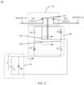
- FIG. 2 is a schematic diagram of a working status of a mechanical switch circuit 200 according to an embodiment of this application.
- the movable coil 210 and the stationary coil 220 attract each other.
- the first switch S 1 and the fourth switch S4 may be controlled to be turned on, and the second switch S2 and the third switch S3 may be controlled to be turned off.
- a current sequentially passes through the first switch S1, the stationary coil 220, the fourth switch S4, and the movable coil 210.
- the current passing through the movable coil 210 and the current passing through the stationary coil 220 are in a same direction. Therefore, the movable coil 210 and the stationary coil 220 attract each other, and the movable coil 210 drives the movable contact to be connected to the stationary contact.
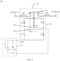
- FIG. 3 is a schematic diagram of a working status of a mechanical switch circuit 200 according to an embodiment of this application.
- the movable coil 210 and the stationary coil 220 repel each other.
- the second switch S2 and the third switch S3 may be controlled to be turned on, and the first switch S 1 and the fourth switch S4 may be controlled to be turned off.
- a current sequentially passes through the second switch S2, the stationary coil 220, the third switch S3, and the movable coil 210.
- the current passing through the movable coil 210 and the current passing through the stationary coil 220 are in opposite directions. Therefore, the movable coil 210 and the stationary coil 220 repel each other, and the movable coil 210 drives the movable contact to be disconnected from the stationary contact.
- on/off of the switch in the switch circuit may be controlled by a control module.
- the control module may be disposed in the mechanical switch circuit 20, or may be independent of the mechanical switch circuit 20. This is not limited in this embodiment of this application.
- the mechanical switch circuit 20 further includes an energy storage module 50.
- the energy storage module 50 is configured to supply a current to the drive module 40, or supply, to the drive module 40, the current that passes through the movable coil 210 and the stationary coil 220.
- the energy storage module 50 may include a capacitor C1, and the capacitor C1 is configured to: store a charge, and supply a current.
- the capacitor C1 may obtain power from the busbar 201 and store the charge.
- the capacitor C1 may obtain power in another manner, for example, obtain the power from a battery. This is not limited in this application.
- the capacitor C 1 may supply a transient high current to fast connect/disconnect the mechanical switch circuit 20.
- a first end of the capacitor C1 is configured to be connected to the first end of the drive module 40, and a second end of the capacitor C1 is configured to be connected to the second end of the drive module 40.
- the capacitor C1 may be an electrolytic capacitor or a film capacitor, or may be a capacitor of another type.
- the energy storage module 50 further includes a diode D5, and the diode D5 and the capacitor C1 are connected in parallel.
- An anode of the diode D5 is connected to the second end of the capacitor C1, and a cathode of the diode D5 is connected to the first end of the capacitor C1.
- Discharge efficiency of C1 can be improved by connecting the diode D5 in parallel at both ends of C1, thereby improving a switching speed of the mechanical switch circuit 20.
- the energy storage module 50 may also use another implementation, provided that the energy storage module 50 can implement a function of supplying the current for the movable coil 210 and the stationary coil 220.
- the energy storage module 50 may also include the battery, and the current is supplied by using the battery.
- the energy storage module 50 may further include a boost converter or a buck converter, to perform level conversion on a received voltage, and then output the current to the movable coil 210 and the stationary coil 220.
- FIG. 4 is a schematic diagram of a circuit breaker 100 according to another embodiment of this application.
- the circuit breaker 100 may further include a solid-state switch circuit 60.
- the solid-state switch circuit 60 and the mechanical switch circuit 20 are connected in parallel.
- the solid-state switch circuit 60 is connected prior to the mechanical switch circuit 20, and when the solid-state switch circuit 60 is disconnected, the mechanical switch circuit 20 is disconnected prior to the solid-state switch circuit 60.
- the circuit breaker 100 adopts a form in which the mechanical switch circuit 20 and the solid-state switch circuit 60 are connected in parallel, and an arc generated when contacts of the mechanical switch circuit 20 are connected or disconnected can be avoided by using the solid-state switch circuit 60. This shortens arcing time, improves a switching speed of the circuit breaker 100, and prolongs a service life of the mechanical switch circuit 20.
- a specific structure of the solid-state switch circuit 60 is not limited in this embodiment of this application, provided that the solid-state switch circuit 60 can implement the foregoing function.
- a specific example of the solid-state switch circuit 60 is described below with reference to FIG. 5 to FIG. 7 .
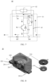
- FIG. 5 is a schematic diagram of a structure of a solid-state switch circuit 60 according to an embodiment of this application.
- the solid-state switch circuit 60 includes a main switch circuit 61, a snubber circuit 62, and a buffer circuit 63.
- the main switch circuit 61 includes diodes D1 to D4, and a switch transistor K1.
- the switch transistor K1 may be an IGBT, an integrated gate-commutated thyristor (integrated gate-commutated thyristor, IGCT), a MOS, or a BJT, or may be a switch device of another type.
- a first end of the solid-state switch circuit 60 is connected to an anode of the diode D1 and a cathode of the diode D2, and a second end of the solid-state switch circuit 60 is connected to an anode of the diode D3 and a cathode of the diode D4.
- a cathode of the diode D1 and a cathode of the diode D3 are connected to a first end of the switch transistor K1, and an anode of the diode D2 and an anode of the diode D4 are connected to a second end of the switch transistor K1.
- the switch transistor K1 is the IGBT
- the first end of the switch transistor K1 is a collector electrode of the IGBT
- the second end of the switch transistor K1 is an emitter electrode of the IGBT.
- the main switch circuit 61 is configured to control the solid-state switch circuit 60 by controlling conduction and disconnection of the switch transistor K1, and the main switch circuit 61 may implement a bidirectional control function.
- FIG. 6 and FIG. 7 separately show schematic diagrams of connection of a solid-state switch circuit 60 in different current directions.
- the diode D1, the switch transistor K1, and the diode D4 may implement a current passage in one direction.
- the diode D3, the switch transistor K1, and the diode D4 may implement a current passage in another direction.
- the snubber circuit 62 may be configured to absorb energy when the switch transistor K1 is disconnected.
- the snubber circuit 62 typically includes a varistor. Varistors can be connected in parallel in the circuit. When the circuit is in normal use, impedance of the varistor is very high, and a leakage current is very small, which may be regarded as disconnected. Little impact is imposed on the circuit. However, when a very high sudden voltage arrives, resistance of the varistor drops instantly. This allows a large current to pass through the varistor, and an overvoltage is clamped to a specific value.
- the buffer circuit 63 is configured to: when the switch transistor K1 is disconnected, protect the switch transistor K1 from being damaged due to the overvoltage, and reduce a disconnection loss of the switch transistor K1.
- a specific structure of the buffer circuit 63 is not limited in this application, provided that the buffer circuit 63 can implement the foregoing function.
- the solid-state switch circuit 60 may not include the buffer circuit 63.
- FIG. 8 is a schematic three-dimensional cross-sectional view of a mechanical switch circuit 20 according to an embodiment of this application.
- the mechanical switch circuit 20 includes the busbar 201, a power module (not marked in the figure), and a drive module (not marked in the figure).
- the power module includes the movable contact 211 and the stationary contact 222.
- the stationary contact 222 is electrically connected to the busbar 201, and the movable contact 211 is movable.
- the mechanical switch circuit 20 is connected, and when the movable contact 211 is disconnected from the stationary contact 222, the mechanical switch circuit 20 is disconnected.
- the drive module includes the movable coil 210 and the stationary coil 220.
- the movable coil 210 and the stationary coil 220 are disposed adjacently, so that the movable coil 210 and the stationary coil 220 attract or repel each other based on whether the current directions are the same.
- the movable coil 210 is configured to drive the movable contact 211 to be connected to or disconnected from the stationary contact 222.
- the movable coil 210 is designed to drive the movable contact 211 to move.
- the movable contact 211 and the movable coil 210 are of the fixed connection structure, or the linkage structure is disposed between the movable contact 211 and the movable coil 210.
- the specific connection manner between the movable contact 211 and the movable coil 210 is not limited in this embodiment of this application, provided that the movable coil 210 can drive the movable contact 211 to move when moving.
- the movable contact 211 and the movable coil 210 may be connected by using the insulating substance, in other words, the movable contact 211 and the movable coil 210 are electrically insulated.
- the insulating substance may include the epoxy resin.
- the busbar 201 includes two parts that are not connected to each other, which may be respectively referred to as the first busbar 201-1 and the second busbar 201-2, and the stationary contact 222 includes the first stationary contact 222-1 and the second stationary contact 222-2 (refer to FIG. 12 ).
- the first stationary contact 222-1 is connected to the first busbar 201-1
- the second stationary contact 222-2 is connected to the second busbar 201-2.
- the first stationary contact 222-1 and the second stationary contact 222-2 are in the electrically disconnected state. Therefore, when the stationary contact 222 is disconnected from the movable contact 211, the first busbar 201-1 and the second busbar 201-2 are in the electrically disconnected state, that is, the mechanical switch circuit 20 is in the disconnected state.
- the movable contact 211 When the stationary contact 222 is connected to the movable contact 211, the movable contact 211 is connected to the first stationary contact 222-1 and the second stationary contact 222-2 to provide the low resistance path between the first busbar 201-1 and the second busbar 201-2, so that the first busbar 201-1 is electrically connected to the second busbar 201-2, that is, the mechanical switch circuit 20 is in the connected state.
- the movable coil 210 is coaxial with the movable contact 211, and the movable coil 210 may drive the movable contact 211 to move up and down in an axial direction.
- the stationary coil 220 is coaxial with the movable coil 210.
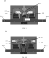
- FIG. 9 is a schematic cross-sectional diagram of a mechanical switch circuit 20 in a connected state according to an embodiment of this application.
- the movable coil 210 and the stationary coil 220 move close to each other, and are placed side by side.
- the current passing through the movable coil 210 and the current passing through the stationary coil 220 are in the opposite directions.
- the movable coil 210 approaches the stationary coil 220, and drives the movable contact 211 to be connected to the stationary contact 222, so that the mechanical switch circuit 20 is connected.
- F contact in FIG. 9 represents a downward suction force applied to the movable coil 210 and the movable contact 211.
- a maintenance apparatus is further disposed in the mechanical switch circuit 20.
- the maintenance apparatus may be configured to: maintain the movable contact 211 and the stationary contact 222 in a contact state after the movable contact 211 is connected to the stationary contact 222, and maintain the movable contact 211 and the stationary contact 222 in a disconnected state after the movable contact 211 is disconnected from the stationary contact 222.
- the maintenance apparatus in FIG. 9 is an electromagnet, and a suction force (F magnet ) generated by the electromagnet may maintain the movable contact 211 and the stationary contact 222 in the contact state.
- F magnet suction force
- FIG. 10 is a schematic cross-sectional diagram of a mechanical switch circuit 20 in a connected state according to an embodiment of this application.
- the current passing through the movable coil 210 and the current passing through the stationary coil 220 are in the same direction.
- the movable coil 210 moves away from the stationary coil 220, and drives the movable contact 211 to be disconnected from the stationary contact 222, so that the mechanical switch circuit 20 is connected.
- F open in FIG. 10 represents an upward repulsion force applied to the movable coil 210 and the movable contact 211.
- a first conductive material is used for a wound coil of the movable coil 210
- a second conductive material is used for a wound coil of the stationary coil 220
- a density of the first conductive material is less than a density of the second conductive material.
- the conductive material of the movable coil 210 may be aluminum
- the conductive material of the stationary coil 220 may be copper.
- a low-density conductive material may be used for the wound coil of the movable coil 210, to reduce mass of the movable coil 210. This further reduces energy required when the movable coil 210 moves, and saves power of the mechanical switch circuit 20.
- a cross section of the movable coil 210 may be smaller than a cross section of the stationary coil 220, so that the mass of the movable coil 210 is smaller than mass of the stationary coil 220.
- FIG. 11 is a top view of a movable coil 210 according to an embodiment of this application. As shown in FIG. 11 , the wound coil of the movable coil 210 may be led out by a flexible conducting wire, so that the armature system can move automatically without being damaged.
- FIG. 12 is a schematic diagram of structures of a movable contact 211 and a stationary contact 222 according to an embodiment of this application.
- the stationary contact includes the first stationary contact 222-1 and the second stationary contact 222-2.
- the movable contact 211 is used to ensure that when the movable contact system is disconnected, the stationary contacts 222 located on both sides are connected, to provide a low resistance path.
- the armature system is activated, the movable coil 210 moves upward in its axial direction, and therefore, drives the movable contact 211 to move together.
- the switching speed of the mechanical switch circuit 20 is related to the distance between the movable coil 210 and the stationary coil 220. For example, the mechanical switch circuit 20 is disconnected.
- a fast disconnection speed of the movable contact 211 can be implemented by reducing the distance between the two coils, so that the switching speed of the mechanical switch circuit 20 can be improved, for example, a switching speed of several hundred ⁇ s (microseconds) can be implemented.
- the movable contact 211 has a protrusion part along a first surface of the movable contact 211, to ensure reliable connection between the movable contact and the stationary contact, thereby improving switching sensitivity of the mechanical switch circuit 20.
- the first surface of the movable contact 211 is configured to be connected to the stationary contact 222.
- a component may be, but is not limited to, a process that runs on a processor, a processor, an object, an executable file, an execution thread, a program, and/or a computer.
- a computing device and an application that runs on the computing device may be components.
- One or more components may reside within a process and/or a thread of execution, and a component may be located on one computer and/or distributed between two or more computers.
- the components may be executed from various computer-readable media that store various data structures.
- the components may communicate by using a local and/or remote process and according to, for example, a signal having one or more data packets (for example, data from two components interacting with another component in a local system, a distributed system, and/or across a network such as the Internet interacting with other systems by using the signal).
- a signal having one or more data packets (for example, data from two components interacting with another component in a local system, a distributed system, and/or across a network such as the Internet interacting with other systems by using the signal).
- the units described as separate parts may or may not be physically separate, and parts displayed as units may or may not be physical units, may be located in one position, or may be distributed on a plurality of network units. Some or all of the units may be selected based on an actual requirement to achieve the objectives of the solutions of embodiments.
- the functions When the functions are implemented in a form of a software functional unit and sold or used as an independent product, the functions may be stored in a computer-readable storage medium. Based on such an understanding, the technical solutions of this application essentially, or the part contributing to the conventional technology, or some of the technical solutions may be implemented in a form of a software product.
- the computer software product is stored in a storage medium, and includes several instructions for instructing a computer device (which may be a personal computer, a server, or a network device) to perform all or some of the steps of the methods described in embodiments of this application.
- the foregoing storage medium includes any medium, for example, a USB flash drive, a removable hard disk, a read-only memory (read-only memory, ROM), a random access memory (random access memory, RAM), a magnetic disk, an optical disc, or the like that can store program code.
Landscapes
- Keying Circuit Devices (AREA)
- Driving Mechanisms And Operating Circuits Of Arc-Extinguishing High-Tension Switches (AREA)
Applications Claiming Priority (1)
| Application Number | Priority Date | Filing Date | Title |
|---|---|---|---|
| PCT/CN2021/084131 WO2022204996A1 (zh) | 2021-03-30 | 2021-03-30 | 断路器和供电系统 |
Publications (2)
| Publication Number | Publication Date |
|---|---|
| EP4303902A1 true EP4303902A1 (de) | 2024-01-10 |
| EP4303902A4 EP4303902A4 (de) | 2024-04-24 |
Family
ID=83455419
Family Applications (1)
| Application Number | Title | Priority Date | Filing Date |
|---|---|---|---|
| EP21933676.5A Withdrawn EP4303902A4 (de) | 2021-03-30 | 2021-03-30 | Schutzschalter und stromversorgungssystem |
Country Status (2)
| Country | Link |
|---|---|
| EP (1) | EP4303902A4 (de) |
| WO (1) | WO2022204996A1 (de) |
Family Cites Families (8)
| Publication number | Priority date | Publication date | Assignee | Title |
|---|---|---|---|---|
| FR2715500B1 (fr) * | 1994-01-25 | 1996-02-16 | Gec Alsthom T & D Sa | Disjoncteur à auto-soufflage et à double mouvement. |
| DE60034297T2 (de) * | 1999-12-06 | 2007-12-20 | Mitsubishi Denki K.K. | Schalteranordnung |
| JP2002124158A (ja) * | 2000-10-16 | 2002-04-26 | Mitsubishi Electric Corp | 開閉装置 |
| EP1538645B1 (de) * | 2003-12-05 | 2006-03-01 | Société Technique pour l'Energie Atomique TECHNICATOME | Hybrid-Leistungsschalter |
| US8686814B2 (en) * | 2010-04-15 | 2014-04-01 | Schneider Electric Industries Sas | Electric switching device with ultra-fast actuating mechanism and hybrid switch comprising one such device |
| CN107769369B (zh) * | 2017-10-25 | 2019-10-25 | 清华大学 | 一种基于耦合负压电路的混合式开关 |
| CN110620022B (zh) * | 2019-09-26 | 2025-07-25 | 宁波兴隆磁性技术有限公司 | 高压大电流磁力保持真空继电器 |
| CN111029190A (zh) * | 2019-11-28 | 2020-04-17 | 贵州电网有限责任公司 | 一种快速切换开关装置、系统及快速切换方法 |
-
2021
- 2021-03-30 EP EP21933676.5A patent/EP4303902A4/de not_active Withdrawn
- 2021-03-30 WO PCT/CN2021/084131 patent/WO2022204996A1/zh not_active Ceased
Also Published As
| Publication number | Publication date |
|---|---|
| EP4303902A4 (de) | 2024-04-24 |
| CN115485802A (zh) | 2022-12-16 |
| US20240013996A1 (en) | 2024-01-11 |
| WO2022204996A1 (zh) | 2022-10-06 |
Similar Documents
| Publication | Publication Date | Title |
|---|---|---|
| CN102349124B (zh) | 用于电切断直流电的断路开关 | |
| EP3200213B1 (de) | Direktstormschutzschalter | |
| EP2904626B1 (de) | Schutzschalter mit gestapelten schaltermodulen | |
| US20150116881A1 (en) | High voltage dc circuit breaker apparatus | |
| US10483072B2 (en) | Interrupter device for interrupting a direct current | |
| CN112997373B (zh) | 具有过压保护的电开关 | |
| CN105122408A (zh) | 电路中断设备 | |
| CN113964788A (zh) | 一种双向直流断路器及开断方法 | |
| EP3522196B1 (de) | Schaltvorrichtung | |
| JP2022094931A (ja) | 送電グリッド用ハイブリッドスイッチング装置 | |
| CN111727487B (zh) | 直流电断路器 | |
| CN114640083A (zh) | 用于电力网的混合开关设备 | |
| US20240038470A1 (en) | Circuit breaker and power supply system | |
| US10236682B2 (en) | Inrush current free switching apparatus and control method thereof | |
| US12597579B2 (en) | Circuit breaker and power supply system | |
| US20240013996A1 (en) | Circuit breaker and power supply system | |
| WO2023077319A1 (zh) | 开关器件、断路器和供电系统 | |
| CN115485802B (zh) | 断路器和供电系统 | |
| CN117292961A (zh) | 新能源车辆、智能接触器及其控制方法 | |
| CN1972052A (zh) | 超导型混合限流开关 | |
| KR102731027B1 (ko) | 전력용 반도체 스위치를 구비한 반도체 회로 차단기 및 그 반도체 회로 차단기를 포함하는 전원 공급 장치 | |
| JP2015230849A (ja) | 開閉器 | |
| EP4338186B1 (de) | Hybridleistungsschalter mit einem vakuumschalter | |
| US20250233445A1 (en) | Backup power box and control method for backup power box | |
| CN210349691U (zh) | 一种中压选相合闸开关 |
Legal Events
| Date | Code | Title | Description |
|---|---|---|---|
| STAA | Information on the status of an ep patent application or granted ep patent |
Free format text: STATUS: THE INTERNATIONAL PUBLICATION HAS BEEN MADE |
|
| PUAI | Public reference made under article 153(3) epc to a published international application that has entered the european phase |
Free format text: ORIGINAL CODE: 0009012 |
|
| STAA | Information on the status of an ep patent application or granted ep patent |
Free format text: STATUS: REQUEST FOR EXAMINATION WAS MADE |
|
| 17P | Request for examination filed |
Effective date: 20231006 |
|
| AK | Designated contracting states |
Kind code of ref document: A1 Designated state(s): AL AT BE BG CH CY CZ DE DK EE ES FI FR GB GR HR HU IE IS IT LI LT LU LV MC MK MT NL NO PL PT RO RS SE SI SK SM TR |
|
| A4 | Supplementary search report drawn up and despatched |
Effective date: 20240326 |
|
| RIC1 | Information provided on ipc code assigned before grant |
Ipc: H01H 33/28 20060101ALI20240320BHEP Ipc: H01H 9/54 20060101ALI20240320BHEP Ipc: H01H 3/22 20060101ALI20240320BHEP Ipc: H01H 33/66 20060101AFI20240320BHEP |
|
| DAV | Request for validation of the european patent (deleted) | ||
| DAX | Request for extension of the european patent (deleted) | ||
| STAA | Information on the status of an ep patent application or granted ep patent |
Free format text: STATUS: THE APPLICATION HAS BEEN WITHDRAWN |
|
| 18W | Application withdrawn |
Effective date: 20240919 |