EP4338186B1 - Hybridleistungsschalter mit einem vakuumschalter - Google Patents
Hybridleistungsschalter mit einem vakuumschalter Download PDFInfo
- Publication number
- EP4338186B1 EP4338186B1 EP22727750.6A EP22727750A EP4338186B1 EP 4338186 B1 EP4338186 B1 EP 4338186B1 EP 22727750 A EP22727750 A EP 22727750A EP 4338186 B1 EP4338186 B1 EP 4338186B1
- Authority
- EP
- European Patent Office
- Prior art keywords
- vacuum interrupter
- circuit breaker
- actuator
- hybrid circuit
- capacitor bank
- Prior art date
- Legal status (The legal status is an assumption and is not a legal conclusion. Google has not performed a legal analysis and makes no representation as to the accuracy of the status listed.)
- Active
Links
Images
Classifications
-
- H—ELECTRICITY
- H01—ELECTRIC ELEMENTS
- H01H—ELECTRIC SWITCHES; RELAYS; SELECTORS; EMERGENCY PROTECTIVE DEVICES
- H01H33/00—High-tension or heavy-current switches with arc-extinguishing or arc-preventing means
- H01H33/60—Switches wherein the means for extinguishing or preventing the arc do not include separate means for obtaining or increasing flow of arc-extinguishing fluid
- H01H33/66—Vacuum switches
- H01H33/666—Operating arrangements
- H01H33/6661—Combination with other type of switch, e.g. for load break switches
-
- H—ELECTRICITY
- H01—ELECTRIC ELEMENTS
- H01H—ELECTRIC SWITCHES; RELAYS; SELECTORS; EMERGENCY PROTECTIVE DEVICES
- H01H33/00—High-tension or heavy-current switches with arc-extinguishing or arc-preventing means
- H01H33/02—Details
- H01H33/59—Circuit arrangements not adapted to a particular application of the switch and not otherwise provided for, e.g. for ensuring operation of the switch at a predetermined point in the AC cycle
-
- H—ELECTRICITY
- H01—ELECTRIC ELEMENTS
- H01H—ELECTRIC SWITCHES; RELAYS; SELECTORS; EMERGENCY PROTECTIVE DEVICES
- H01H9/00—Details of switching devices, not covered by groups H01H1/00 - H01H7/00
- H01H9/54—Circuit arrangements not adapted to a particular application of the switching device and for which no provision exists elsewhere
- H01H9/541—Contacts shunted by semiconductor devices
- H01H9/542—Contacts shunted by static switch means
- H01H2009/543—Contacts shunted by static switch means third parallel branch comprising an energy absorber, e.g. MOV, PTC, Zener
-
- H—ELECTRICITY
- H01—ELECTRIC ELEMENTS
- H01H—ELECTRIC SWITCHES; RELAYS; SELECTORS; EMERGENCY PROTECTIVE DEVICES
- H01H9/00—Details of switching devices, not covered by groups H01H1/00 - H01H7/00
- H01H9/54—Circuit arrangements not adapted to a particular application of the switching device and for which no provision exists elsewhere
- H01H9/541—Contacts shunted by semiconductor devices
- H01H9/542—Contacts shunted by static switch means
Definitions
- the invention relates to a hybrid circuit breaker, which comprises an input connector prepared to be connected to a power grid, an output connector prepared to be connected to a load and a current path connecting the input connector and the output connector.
- the hybrid circuit breaker comprises an electro-mechanical bypass switch being arranged in the current path and a semiconductor circuit in parallel with the electro-mechanical bypass switch.
- the hybrid circuit breaker comprises a control unit being capable of controlling a commutation from the current path, in which the electro-mechanical bypass switch is arranged, to the semiconductor circuit in case of a switch off operation of the hybrid circuit breaker.
- GB 2 375 902 A discloses a hybrid fault current limiting and interrupting device for protecting an electric power line.
- the device comprises a power circuit including a solid-state switching component, a voltage clamping element connected in parallel with the switching component, a circuit breaker connected in parallel with the switching component and with the voltage clamping element, an isolating switch to the supply side of the switching component, and a current sensor.
- the device further comprises a control circuit including a fault current detector and estimator and a switching pattern controller, the arrangement being such that, on detection of a fault current by the detector, the circuit breaker is opened and the fault current is transferred to the switching component which is turned on during the final stage of current interruption by the circuit breaker.
- US 2020/411262 A1 discloses a circuit breaker including a pole unit with a moveable electrode and a fixed electrode.
- a resilient member is operably connected to a first end of the pole unit.
- a linkage extends from the second end of the pole unit and operably connects to the moveable electrode.
- a linear actuator is operably connected to the linkage and located away from the pole unit.
- a Thomson coil or other high-speed actuator is also operably connected to the linkage.
- a gap is provided between the pole unit and the linear actuator member when the resilient member is not extended.
- the high-speed actuator first acts on the linkage by pulling the movable electrode away from the fixed electrode. The linear actuator then actuates and increases the distance between the contacts of the breaker by pulling the pole unit toward it, closing the gap.
- US 2020/343062 A1 discloses a direct current breaker based on vacuum magnetic blowout transfer and a breaking method thereof.
- the direct current breaker includes a first connection terminal, a second connection terminal, a main current branch, a transfer branch, an energy dissipation branch and a blowout unit.
- the main current branch is connected between the first connection terminal and the second connection terminal.
- the transfer branch is connected between the first connection terminal and the second connection terminal and connected in parallel with the main current branch.
- the energy dissipation branch is connected between the first connection terminal and the second connection terminal and connected in parallel with the main current branch and the transfer branch.
- the blowout unit is arranged between the main current branch and the transfer branch.
- Genji T et al. (“400V class high-speed current limiting circuit breaker for electric power system", IEEE Transactions on Power Delivery, vol. 9, no. 3, 1994 ) discloses a high-speed current limiting equipment using gate turn-off thyristors (GTOs).
- GTOs gate turn-off thyristors
- a hybrid circuit breaker as defined above is generally known and disclosed in US 9,947,496 B2 for example.
- the electro-mechanical bypass switch When the electro-mechanical bypass switch is opened due to e.g. an overload condition at the output connectors (e.g. because of an arc fault or a short circuit in the load or in a circuit leading to the load), a current over the switching contacts of the electro-mechanical bypass switch is passed over or commutated to the semiconductor circuit.
- an arc voltage is generated between the contacts of the electro-mechanical bypass switch when they are opened causing the current commutation from the bypass switch to the semiconductor switch.
- the current through the hybrid circuit breaker does not longer flow over the electro-mechanical bypass switch but flows over to the semiconductor circuit.
- a hybrid circuit breaker combines the advantages of an electro-mechanical circuit breaker, which offers a very low on-state resistance but is prone to damages of the switching contacts due to massive arcing, and of a solid-state circuit breaker, which has no mechanical switching contacts but has a comparably high on-state resistance.
- a drawback of a hybrid circuit breaker is that it gets bulky when it has to conduct larger nominal currents because the semiconductor circuit has to withstand very high over currents and fault currents then. Accordingly, it also has to absorb very high electric energy, which results in substantial electrical stress on the components of the hybrid circuit breaker, in particular on the semiconductor circuit. Moreover, the electric energy is converted to thermal energy in the semiconductor circuit, which has to be absorbed and dissipated. In common concepts, the semiconductor circuit is made so massive that it can withstand that high over and fault currents so that, as said, the hybrid circuit breaker gets bulky when it comes to high currents.
- Cooling of the semiconductor circuit in principle is possible, too, but it is technically complicated and challenging. The reason is that the thermal energy is generated very fast, in other words the thermal power is very high, and cooling has to take place close to the junction of the semiconductor parts to be effective.
- the outer surface of common housings is not suitable for cooling because of the thermal resistance between the junction and the outer surface and because of the thermal capacitance of the housing. In other words, cooling through the outer surface is too slow.
- the current does not immediately reach its top level when there is an arc fault or short circuit, but there is a steep current rise due to the grid's impedance. Because opening of the contacts to reach enough mechanical distance in order to establish the required dielectric strength takes some time, the semiconductor circuit conducts the worse part of the overload, i.e. the part with the higher currents. It is easy to understand that things become worse the longer it takes until current has commutated to the semiconductor circuit.
- a problem of the invention is to provide an improved hybrid circuit breaker.
- the size of and the costs for the semiconductor circuit of the hybrid circuit breaker shall be reduced, especially for high nominal currents.
- the technical and economic limit for the use of hybrid circuit breakers shall be shifted to higher nominal currents without increasing the size and cost of the hybrid circuit breaker.
- a hybrid circuit breaker as defined in claim 1, wherein the electro-mechanical bypass switch is embodied as a vacuum interrupter, which comprises a switching contact and an actuator being designed to drive the switching contact of the vacuum interrupter.
- the electric energy, which the semiconductor circuit has to absorb is substantially lower than in common hybrid circuit breaker designs. That results in a reduction of the electrical stress on the components of the hybrid circuit breaker in general and in particular on the semiconductor circuit.
- the hybrid circuit breaker can withstand higher over currents in general and can be used for higher nominal currents without increasing the size of the semiconductor circuit.
- the technical and economic limit for the use of hybrid circuit breakers is shifted to higher nominal currents. So, a larger range of electrical installations may benefit from the advantages of a hybrid circuit breaker.
- hybrid circuit breaker of the proposed kind can be used in AC applications as well as in DC applications.
- the actuator of the vacuum interrupter can be embodied as an electrodynamic actuator comprising a voice coil being movably arranged in a magnetic field.
- the electrodynamic actuator can comprise a permanent magnet with an iron core being designed to guide a magnetic field generated by the permanent magnet, wherein the voice coil is movably arranged in an air gap of the iron core and flown through by said magnetic field.
- An electrodynamic actuator can generate comparably high forces at low strokes and thus it advantageously can be used for the proposed hybrid circuit breaker. Because of the high driving forces, the switching contact of the vacuum interrupter opens very fast hence assisting to keep currents in the semiconductor circuit low.
- a "voice coil” may equally termed "moving coil” throughout the description.
- the hybrid circuit breaker comprises a first capacitor bank, which is electrically connected to the actuator of the vacuum interrupter in a switchable manner and which is designed to assist opening the switching contact of the vacuum interrupter when the first capacitor bank is switched to the actuator.
- the control unit is additionally designed to switch the first capacitor bank to the actuator of the vacuum interrupter in a first polarity in case of a switch off operation.
- the switching contact of the vacuum interrupter can be opened even faster.
- the actuator of the vacuum interrupter is embodied as an electrodynamic actuator.
- the first capacitor bank (in this first polarity) can be disconnected from the actuator of the vacuum interrupter again for example once the switching contact of the vacuum interrupter is opened or in case of a switch on operation.
- the control unit is additionally designed to switch the first capacitor bank to the actuator of the vacuum interrupter in a second opposite polarity in case of a switch on operation.
- the first capacitor bank can also be used for closing the switching contact of the vacuum interrupter very fast. This can also help to reduce contact degradation.
- the first capacitor bank (in this second polarity) can be disconnected from the actuator of the vacuum interrupter again for example once the switching contact of the vacuum interrupter is closed or in case of a switch off operation.
- the hybrid circuit breaker comprises a second capacitor bank, which is electrically connected to the actuator of the vacuum interrupter in a switchable manner and which is designed to assist closing the switching contact of the vacuum interrupter when the second capacitor bank is switched to the actuator.
- the control unit additionally can be designed to switch the second capacitor bank to the actuator of the vacuum interrupter (in a second opposite polarity) in case of a switch on operation. This is another possibility to assist closing the switching contact of the vacuum interrupter very fast.
- the second capacitor bank (in this second polarity) can be disconnected from the actuator of the vacuum interrupter again for example once the switching contact of the vacuum interrupter is closed or in case of a switch off operation.
- the first capacitor bank and/or the second capacitor bank is part of the control unit. In this way, the number of parts for the hybrid circuit breaker can be reduced.
- the first capacitor bank has a higher capacity than the second capacitor bank. So, opening the switching contact of the vacuum interrupter does happen faster than closing the same. By these features, priority is laid on a fast opening of the switching contact of the vacuum interrupter so as to keep the overall size for the capacitor banks small.
- the switching contact of the vacuum interrupter is held in its closed or in its open position by means of a mechanical latch. So, no continuous electromagnetic force is needed to hold the switching contact of the vacuum interrupter in the closed or open position.
- a latch can be combined with a spring to obtain bistable behavior of the switching contact of the vacuum interrupter meaning that a driving force is just needed to change between the on-state and the off-state of the switching contact of the vacuum interrupter, but not to keep the on-state and the off-state.
- all-pole breaking of the grid can be enabled if the vacuum interrupter has just a one-pole switching contact.
- a one-pole switching contact for the vacuum interrupter is of advantage because of the lower moving mass.
- the vacuum interrupter can also have an all-pole switching contact. If so, no relay is needed for galvanic separation.
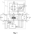
- Fig. 1 shows an exemplary hybrid circuit breaker 1, which comprises an input connector 2a, 2b for a power grid, an output connector 3a, 3b for a load RL and a current path 4a, 4b connecting the input connector 2a, 2b and the output connector 3a, 3b. Furthermore, the hybrid circuit breaker 1 comprises an electro-mechanical bypass switch 5 in the current path 4a and an exemplary semiconductor circuit 6 in parallel with the electro-mechanical bypass switch 5.
- the electro-mechanical bypass switch 5 is embodied as a vacuum interrupter, which comprises a switching contact S1 being arranged in a vacuum chamber B and an actuator 7 being designed to drive the switching contact S1 of the vacuum interrupter 5.
- the semiconductor circuit 6 comprises a rectifier D1..D4, the inputs of which are connected to the endpoints of the series connection of the electro-mechanical bypass switch 5.
- two parallel transistors T1, T2 (here in detail IGBTs) are switched between the outputs of the rectifier D1..D4.
- IGBTs in detail transistors
- a different number of transistors T1, T2 may be used instead.
- an optional snubber circuit 8 is arranged in parallel with the two transistors T1, T2.
- the snubber circuit 8 comprises a series connection of a snubber resistor R1 and a snubber capacitor C and a snubber diode D5 in parallel with the snubber resistor R1.
- the hybrid circuit breaker 1 furthermore comprises a varistor R2, which is connected to the endpoints of the series connection of the electro-mechanical bypass switch 5 and forms an overvoltage protection for the same.
- the hybrid circuit breaker 1 comprises a shunt R3, the terminals of which are connected to inputs of a control unit CTRL and which serves for measuring a current I flowing over the input connector 2a.
- the control unit CTRL is not only for measuring the current I but is also being capable of controlling a commutation from the current path 4a, in which the electro-mechanical bypass switch 5 is arranged, to the semiconductor circuit 6 in case of a switching operation (e.g. in case of an over current through the electro-mechanical bypass switch 5).
- commutation can be initiated when the electro-mechanical bypass switch 5 is opened by the control unit CTRL and an arc voltage is generated.
- the outputs of the control unit CTRL are connected to the input terminals of the electro-mechanical bypass switch 5 and to the transistors T1, T2.
- the control unit CTRL is powered by a power unit 9, which is connected to the current path 4a, 4b and converts the voltage coming from the grid voltage source VG into a voltage which is suitable for the control unit CTRL.
- the hybrid circuit breaker 1 comprises an optional relay 10 with relay switching contacts S2, S3 in the current paths 4a, 4b providing a galvanic separation.
- Outputs of the control unit CTRL may be connected to the input terminals of the relay switching contacts S2, S3, too.
- all-pole breaking of the grid can be enabled if the vacuum interrupter 5 has just a one-pole switching contact like this is shown in Fig. 1 .
- a one-pole switching contact for the vacuum interrupter 5 is of advantage because of the lower moving mass. However, nevertheless the vacuum interrupter 5 can also have an all-pole switching contact. If so, no relay 10 is needed for galvanic separation.
- Fig. 1 also shows a grid voltage source VG connected to the input connector 2a, 2b of the hybrid circuit breaker 1.
- a load RL At the output connector 2a, 2b there is connected a load RL and also shown an electrical fault EF, for example in the form of a short circuit or an arc flash.
- the parts of the hybrid circuit breaker 1 preferably are arranged in a common housing. However, a modular design is possible as well.
- the actuator 7 of the mechanical bypass switch 5 is embodied as an electrodynamic actuator comprising a voice coil 11 being movably arranged in a magnetic field.
- the electrodynamic actuator 7 may comprise a permanent magnet 12 with an iron core 13 being designed to guide a magnetic field generated by the permanent magnet 12 as this is depicted in the example of Fig. 1 .
- the voice coil 11 is movably arranged in an air gap of the iron core 13 and flown through by said magnetic field.
- the voice coil 11 is connected to the switching contact S1 of the vacuum interrupter 5 by means of a rod 14.
- An electrodynamic actuator 7 can generate comparably high forces at low strokes and thus it advantageously can be used for the proposed hybrid circuit breaker 1. Because of the high driving forces, the switching contact S1 of the vacuum interrupter 5 opens very fast hence assisting to keep currents in the semiconductor circuit 6 low.
- an first capacitor bank 15 is electrically connected to the actuator 7 of the vacuum interrupter 5 in a switchable manner and assists opening the switching contact S1 of the vacuum interrupter 5 when the first capacitor bank 15 is switched to the actuator 7 (in this example to its voice coil 11).
- the control unit CTRL is designed to switch the first capacitor bank 15 to the actuator 7 of the vacuum interrupter 5 in a first polarity in case of a switch off operation.
- the first capacitor bank 15 in this first polarity can be disconnected from the actuator 7 of the vacuum interrupter 5 again for example once the switching contact S1 of the vacuum interrupter 5 is opened or in case of a switch on operation. Switching the first capacitor bank 15 to and from the actuator 7 takes place by toggling the first bank switching contact S4. Additional measures could be useful to close the switching contact S1 of the vacuum interrupter 5 and/or to keep it open as this is depicted in Figs. 2 to 6 .
- the switching contact S1 of the vacuum interrupter 5 can be opened even faster. This is particularly true if the actuator 7 of the vacuum interrupter 5 is embodied as an electrodynamic actuator like this is the case in Fig. 1 .
- the basic function of the hybrid circuit breaker 1 is as follows: If the current I, which is measured by use of the shunt R3, exceeds a current limit, the control unit CTRL switches the first capacitor bank 15 to the actuator 7 by use of the first bank switching contact S4 what in turn causes opening the switching contact S1 of the vacuum interrupter 5. In addition, the control unit CTRL also drives the transistors T1, T2 thus causing a current commutation from the vacuum interrupter 5 to the semiconductor circuit 6. Finally, the relay 10 is opened by the control unit CTRL providing galvanic separation. For switching on the hybrid circuit breaker 1, the control unit CTRL closes the relay 10 and switches off the transistors T1, T2. Then, the switching contact S1 of the vacuum interrupter 5 is closed.
- the first capacitor bank 15 and the relay 10 are optional.
- the actuator 7 can also be switched directly to the power unit 9 and a one-pole switch off can be considered as sufficient.
- the vacuum interrupter 5 can also have more than one switching contact S1.
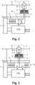
- Fig. 2 shows a cutout of an alternative hybrid circuit breaker 1, which is different to that of Fig. 1 .
- the control unit CTRL is additionally designed to switch the first capacitor bank 15 to the actuator 7 of the vacuum interrupter 5 in a second opposite polarity in case of a switch on operation.
- the first bank switching contact S4 is designed as a two-pole switch which reverses the polarity of the voltage, which is fed to the actuator 7 of the vacuum interrupter 5.
- the first capacitor bank 15 is not only used for opening the switching contact S1 of the vacuum interrupter 5 but can also be used for closing the switching contact S1 of the vacuum interrupter 5 very fast. This can also help to reduce contact degradation.
- Fig. 3 shows a cutout of another alternative hybrid circuit breaker 1, which is different to that of Fig. 1 .
- a second capacitor bank 16 which is electrically connected to the actuator 7 of the vacuum interrupter 5 in a switchable manner and which is designed to assist closing the switching contact S1 of the vacuum interrupter 5 when the second capacitor bank 16 is switched to the actuator 7.
- the control unit CTRL is additionally designed to switch the second capacitor bank 16 to the actuator 7 of the vacuum interrupter 5 (in a second opposite polarity) in case of a switch on operation by use of the second bank switching contact S5. This is another possibility to assist closing the switching contact S1 of the vacuum interrupter 5 very fast.
- the second capacitor bank 16 in the second polarity can be disconnected from the actuator 7 of the vacuum interrupter 5 again for example once the switching contact S1 of the vacuum interrupter 5 is closed or in case of a switch off operation.
- the capacitor bank 15 and the second capacitor bank 16 are separate modules out of the control unit CTRL.
- the first capacitor bank 15 and/or the second capacitor bank 16 may also be part of the control unit CTRL. In this way, the number of parts for the hybrid circuit breaker 1 can be reduced.
- the first capacitor bank 15 has a higher capacity than the second capacitor bank 16 like this is visualized in Fig. 3 by the higher number of capacitors in the first capacitor bank 15.
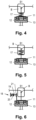
- Fig. 4 shows another (smaller) cutout of an alternative hybrid circuit breaker 1, which is different to that of Fig. 1 .
- the switching contact S1 of the vacuum interrupter 5 is held in its open position by means of a spring 17 and is designed to be closed by applying a current to the actuator 7. So, no continuous electromagnetic force is needed to hold the switching contact S1 of the vacuum interrupter 5 in the open position.
- This embodiment is particularly helpful in combination with an actuator 7, which only is designed to close the switching contact S1 of the vacuum interrupter 5.
- Fig. 5 is quite similar to Fig. 4 .
- the switching contact S1 of the vacuum interrupter 5 is held in its closed position by means of a spring 17 and is designed to be opened by applying a current to the actuator 7. So, no continuous electromagnetic force is needed to hold the switching contact S1 of the vacuum interrupter 5 in the closed position.
- This embodiment is particularly helpful in combination with an actuator 7, which only is designed to open the switching contact S1 of the vacuum interrupter 5.
- Fig. 6 shows a cutout of an alternative hybrid circuit breaker 1, which again is different to that of Fig. 1 .
- the switching contact S1 of the vacuum interrupter 5 is held in its open position by means of a mechanical latch 18.
- the latch 18 comprises a pin 19 biased by a spring 20 and a pawl 21 connected to the voice coil 11.
- the voice coil 11 moves down, the pin 19 locks the pawl 21 and thus the switching contact S1 of the vacuum interrupter 5.
- this is another embodiment where no continuous electromagnetic force is needed to hold the switching contact S1 of the vacuum interrupter 5 in the open position.
- some kind of unlocking mechanism is needed, which for the sake of brevity however is not shown in Fig. 6 .
- the pawl 21 may also built in in the reverse direction so that the switching contact S1 of the vacuum interrupter 5 is latched in its closed position. This embodiment is particularly helpful in combination with an actuator 7, which shall not need to be activated all the time to hold the switching contact S1 of the vacuum interrupter 5 in its open or closed position.
- the hybrid circuit breaker 1 may have more or less parts than shown in the figures.
Landscapes
- Engineering & Computer Science (AREA)
- Power Engineering (AREA)
- High-Tension Arc-Extinguishing Switches Without Spraying Means (AREA)
Claims (10)
- Hybridleistungsschalter (1), umfassend- einen Eingangsanschluss (2a, 2b), der für den Anschluss an ein Stromnetz eingerichtet ist,- einen Ausgangsanschluss (3a, 3b), der für den Anschluss an eine Last (RL) eingerichtet ist,- einen Strompfad (4a, 4b), der den Eingangsanschluss (2a, 2b) und den Ausgangsanschluss (3a, 3b) verbindet,- einen elektromechanischen Bypass-Schalter (5), der in dem Strompfad (4a, 4b) angeordnet ist,- eine Halbleiterschaltung (6) parallel zu dem elektromechanischen Bypass-Schalter (5) und- eine Steuereinheit (CTRL), die in der Lage ist, eine Kommutierung von dem Strompfad (4a, 4b), in dem der elektromechanische Bypass-Schalter (5) angeordnet ist, zu der Halbleiterschaltung (6) im Falle einer Ausschaltoperation zu steuern,- wobei der elektromechanische Bypass-Schalter (5) als Vakuumschalter ausgeführt ist, der einen Schaltkontakt (S1) und einen Betätiger (7) umfasst, der so ausgelegt ist, dass er den Schaltkontakt (S1) des Vakuumschalters (5) betätigt, dadurch gekennzeichnet, dass der Hybrid-Leistungsschalter ferner umfasst:- eine erste Kondensatorbank (15), die elektrisch mit dem Betätiger (7) des Vakuumschalters (5) in einer schaltbaren Weise verbunden ist und die dazu ausgelegt ist, die Öffnung des Schaltkontakts (S1) des Vakuumschalters (5) zu unterstützen, wenn die erste Kondensatorbank (15) zu dem Betätiger geschaltet wird,- wobei die Steuereinheit (CTRL) zusätzlich so ausgelegt ist, dass sie die erste Kondensatorbank (15) im Falle einer Ausschaltoperation in einer ersten Polarität an den Betätiger (7) des Vakuumschalters (5) schaltet und die erste Kondensatorbank (15) im Falle einer Einschaltoperation in einer zweiten entgegengesetzten Polarität an den Betätiger (7) des Vakuumschalters (5) schaltet.
- Hybridleistungsschalter (1) nach Anspruch 1, dadurch gekennzeichnet, dass der Betätiger (7) des Vakuumschalters (5) als elektrodynamischer Betätiger ausgebildet ist, umfassend eine beweglich in einem Magnetfeld angeordnete Schwingspule (11).
- Hybridleistungsschalter (1) nach Anspruch 2, dadurch gekennzeichnet, dass der elektrodynamische Betätiger (7) einen Permanentmagneten (12) mit einem Eisenkern (13) umfasst, der so ausgelegt ist, dass er ein von dem Permanentmagneten (12) erzeugtes Magnetfeld führt, wobei die Schwingspule (11) beweglich in einem Zwischenraum des Eisenkerns (13) angeordnet ist und von dem Magnetfeld durchflossen wird.
- Hybridleistungsschalter (1) nach einem der Ansprüche 1 bis 3, gekennzeichnet durch eine zweite Kondensatorbank (16), die mit dem Betätiger (7) des Vakuumschalters (5) in einer schaltbaren Weise elektrisch verbunden ist und die dazu ausgelegt ist, das Schließen des Schaltkontakts (S1) des Vakuumschalters (5) zu unterstützen, wenn die zweite Kondensatorbank (16) auf den Betätiger (7) geschaltet ist.
- Hybridleistungsschalter (1) nach Anspruch 4, dadurch gekennzeichnet, dass die Steuereinheit (CTRL) zusätzlich so ausgelegt ist, dass sie die zweite Kondensatorbank (16) im Falle einer Einschaltoperation an den Betätiger (7) des Vakuumschalters (5) schaltet.
- Hybridleistungsschalter (1) nach einem der Ansprüche 4 bis 5, dadurch gekennzeichnet, dass die erste Kondensatorbank (15) und/oder die zweite Kondensatorbank (16) Teil der Steuereinheit (CTRL) ist.
- Hybridleistungsschalter (1) nach einem der Ansprüche 4 bis 6, dadurch gekennzeichnet, dass die erste Kondensatorbank (15) eine höhere Kapazität als die zweite Kondensatorbank (16) aufweist.
- Hybridleistungsschalter (1) nach einem der Ansprüche 1 bis 7, dadurch gekennzeichnet, dass der Schaltkontakt (S1) des Vakuumschalters (5) mittels einer mechanischen Verriegelung (18) in seiner geschlossenen oder in seiner geöffneten Position gehalten wird.
- Hybridleistungsschalter (1) nach einem der Ansprüche 1 bis 7, dadurch gekennzeichnet, dass- der Schaltkontakt (S1) des Vakuumschalters (5) mittels einer Feder (17) in seiner geschlossenen Position gehalten wird und so ausgelegt ist, dass er durch Anwenden eines Stroms auf den Betätiger (7) geöffnet wird, oder- der Schaltkontakt (S1) des Vakuumschalters (5) mittels einer Feder (17) in seiner geöffneten Position gehalten wird und so ausgelegt ist, dass er durch Anwenden eines Stroms auf den Betätiger (7) geschlossen wird.
- Hybridleistungsschalter (1) nach einem der Ansprüche 1 bis 9, dadurch gekennzeichnet, dass- der Hybridleistungsschalter (1) zusätzlich ein Relais (10) umfasst, das in Reihe mit dem Vakuumschalter (5) geschaltet ist, und- die Steuereinheit (CTRL) zusätzlich so ausgelegt ist, dass sie das Relais (10) öffnet, nachdem der Vakuumschalter (5) geöffnet wurde.
Applications Claiming Priority (3)
| Application Number | Priority Date | Filing Date | Title |
|---|---|---|---|
| IN202111021278 | 2021-05-11 | ||
| GB2108896.8A GB2606587A (en) | 2021-05-11 | 2021-06-21 | Hybrid circuit breaker with a vacuum interrupter |
| PCT/EP2022/025212 WO2022238009A1 (en) | 2021-05-11 | 2022-05-06 | Hybrid circuit breaker with a vacuum interrupter |
Publications (2)
| Publication Number | Publication Date |
|---|---|
| EP4338186A1 EP4338186A1 (de) | 2024-03-20 |
| EP4338186B1 true EP4338186B1 (de) | 2025-06-25 |
Family
ID=81940599
Family Applications (1)
| Application Number | Title | Priority Date | Filing Date |
|---|---|---|---|
| EP22727750.6A Active EP4338186B1 (de) | 2021-05-11 | 2022-05-06 | Hybridleistungsschalter mit einem vakuumschalter |
Country Status (3)
| Country | Link |
|---|---|
| US (1) | US12437944B2 (de) |
| EP (1) | EP4338186B1 (de) |
| WO (1) | WO2022238009A1 (de) |
Family Cites Families (6)
| Publication number | Priority date | Publication date | Assignee | Title |
|---|---|---|---|---|
| US6331687B1 (en) * | 1995-05-15 | 2001-12-18 | Cooper Industries Inc. | Control method and device for a switchgear actuator |
| US6538347B1 (en) * | 1995-05-15 | 2003-03-25 | Mcgraw-Edison Company | Electrical switchgear with synchronous control system and actuator |
| GB0103748D0 (en) * | 2001-02-15 | 2001-04-04 | Univ Northumbria Newcastle | A Hybrid fault current limiting and interrupting device |
| WO2015028634A1 (en) * | 2013-08-30 | 2015-03-05 | Eaton Industries (Netherlands) B.V. | Circuit breaker with hybrid switch |
| CN109935479A (zh) * | 2019-04-23 | 2019-06-25 | 西安交通大学 | 基于真空磁吹转移的直流断路器及其开断方法 |
| US11107653B2 (en) * | 2019-06-26 | 2021-08-31 | Eaton Intelligent Power Limited | Dual-action switching mechanism and pole unit for circuit breaker |
-
2022
- 2022-05-06 WO PCT/EP2022/025212 patent/WO2022238009A1/en not_active Ceased
- 2022-05-06 EP EP22727750.6A patent/EP4338186B1/de active Active
- 2022-05-06 US US18/559,507 patent/US12437944B2/en active Active
Also Published As
| Publication number | Publication date |
|---|---|
| EP4338186A1 (de) | 2024-03-20 |
| US12437944B2 (en) | 2025-10-07 |
| US20240258050A1 (en) | 2024-08-01 |
| WO2022238009A1 (en) | 2022-11-17 |
Similar Documents
| Publication | Publication Date | Title |
|---|---|---|
| Shukla et al. | A survey on hybrid circuit-breaker topologies | |
| US7542250B2 (en) | Micro-electromechanical system based electric motor starter | |
| EP3651175B1 (de) | Leistungsschalter mit verringerter anforderung an die durchbruchspannung | |
| CN101252055B (zh) | 断路器及其开闭方法 | |
| US10116132B2 (en) | Device for efficient direct current interruption | |
| EP3200213B1 (de) | Direktstormschutzschalter | |
| EP3116006B1 (de) | Kapazitive kopplungsartige lichtbogenlöschschaltung und vorrichtung | |
| CN109997208B (zh) | 低压断路器装置 | |
| Peng et al. | Current commutation in a medium voltage hybrid DC circuit breaker using 15 kV vacuum switch and SiC devices | |
| GB2606587A (en) | Hybrid circuit breaker with a vacuum interrupter | |
| CN111937110B (zh) | 开关设备 | |
| EP3522196B1 (de) | Schaltvorrichtung | |
| AU767295B2 (en) | High-speed current-limiting switch | |
| US12586739B2 (en) | Hybrid circuit breaker with improved current capacity per device size | |
| Askan et al. | Variable voltage IGBT gate driver for low voltage hybrid circuit breaker | |
| EP4338186B1 (de) | Hybridleistungsschalter mit einem vakuumschalter | |
| EP4300528B1 (de) | Schutzschalter und stromversorgungssystem | |
| EP3913647B1 (de) | Schaltersystem | |
| CN206060023U (zh) | 智能控制永磁操动高压选相合闸开关 | |
| KR20160143141A (ko) | 고속 스위치 | |
| EP3982539B1 (de) | Schaltanordnung | |
| CN120261237A (zh) | 一种低压混合式断路器及其工作方法 | |
| WO2025098709A1 (en) | Switch arrangement and method for operating a switch arrangement | |
| CN1258083A (zh) | 限流开关的接触装置 | |
| WO2022204996A1 (zh) | 断路器和供电系统 |
Legal Events
| Date | Code | Title | Description |
|---|---|---|---|
| STAA | Information on the status of an ep patent application or granted ep patent |
Free format text: STATUS: UNKNOWN |
|
| STAA | Information on the status of an ep patent application or granted ep patent |
Free format text: STATUS: THE INTERNATIONAL PUBLICATION HAS BEEN MADE |
|
| PUAI | Public reference made under article 153(3) epc to a published international application that has entered the european phase |
Free format text: ORIGINAL CODE: 0009012 |
|
| STAA | Information on the status of an ep patent application or granted ep patent |
Free format text: STATUS: REQUEST FOR EXAMINATION WAS MADE |
|
| 17P | Request for examination filed |
Effective date: 20231116 |
|
| AK | Designated contracting states |
Kind code of ref document: A1 Designated state(s): AL AT BE BG CH CY CZ DE DK EE ES FI FR GB GR HR HU IE IS IT LI LT LU LV MC MK MT NL NO PL PT RO RS SE SI SK SM TR |
|
| DAV | Request for validation of the european patent (deleted) | ||
| DAX | Request for extension of the european patent (deleted) | ||
| GRAP | Despatch of communication of intention to grant a patent |
Free format text: ORIGINAL CODE: EPIDOSNIGR1 |
|
| STAA | Information on the status of an ep patent application or granted ep patent |
Free format text: STATUS: GRANT OF PATENT IS INTENDED |
|
| INTG | Intention to grant announced |
Effective date: 20241219 |
|
| GRAS | Grant fee paid |
Free format text: ORIGINAL CODE: EPIDOSNIGR3 |
|
| P01 | Opt-out of the competence of the unified patent court (upc) registered |
Free format text: CASE NUMBER: APP_15117/2025 Effective date: 20250327 |
|
| GRAA | (expected) grant |
Free format text: ORIGINAL CODE: 0009210 |
|
| STAA | Information on the status of an ep patent application or granted ep patent |
Free format text: STATUS: THE PATENT HAS BEEN GRANTED |
|
| AK | Designated contracting states |
Kind code of ref document: B1 Designated state(s): AL AT BE BG CH CY CZ DE DK EE ES FI FR GB GR HR HU IE IS IT LI LT LU LV MC MK MT NL NO PL PT RO RS SE SI SK SM TR |
|
| REG | Reference to a national code |
Ref country code: GB Ref legal event code: FG4D |
|
| REG | Reference to a national code |
Ref country code: CH Ref legal event code: EP |
|
| REG | Reference to a national code |
Ref country code: CH Ref legal event code: EP |
|
| REG | Reference to a national code |
Ref country code: IE Ref legal event code: FG4D |
|
| REG | Reference to a national code |
Ref country code: DE Ref legal event code: R096 Ref document number: 602022016474 Country of ref document: DE |
|
| REG | Reference to a national code |
Ref country code: NL Ref legal event code: FP |
|
| PG25 | Lapsed in a contracting state [announced via postgrant information from national office to epo] |
Ref country code: FI Free format text: LAPSE BECAUSE OF FAILURE TO SUBMIT A TRANSLATION OF THE DESCRIPTION OR TO PAY THE FEE WITHIN THE PRESCRIBED TIME-LIMIT Effective date: 20250625 |
|
| REG | Reference to a national code |
Ref country code: LT Ref legal event code: MG9D |
|
| PG25 | Lapsed in a contracting state [announced via postgrant information from national office to epo] |
Ref country code: NO Free format text: LAPSE BECAUSE OF FAILURE TO SUBMIT A TRANSLATION OF THE DESCRIPTION OR TO PAY THE FEE WITHIN THE PRESCRIBED TIME-LIMIT Effective date: 20250925 Ref country code: GR Free format text: LAPSE BECAUSE OF FAILURE TO SUBMIT A TRANSLATION OF THE DESCRIPTION OR TO PAY THE FEE WITHIN THE PRESCRIBED TIME-LIMIT Effective date: 20250926 |
|
| PG25 | Lapsed in a contracting state [announced via postgrant information from national office to epo] |
Ref country code: BG Free format text: LAPSE BECAUSE OF FAILURE TO SUBMIT A TRANSLATION OF THE DESCRIPTION OR TO PAY THE FEE WITHIN THE PRESCRIBED TIME-LIMIT Effective date: 20250625 |
|
| PG25 | Lapsed in a contracting state [announced via postgrant information from national office to epo] |
Ref country code: HR Free format text: LAPSE BECAUSE OF FAILURE TO SUBMIT A TRANSLATION OF THE DESCRIPTION OR TO PAY THE FEE WITHIN THE PRESCRIBED TIME-LIMIT Effective date: 20250625 |
|
| PG25 | Lapsed in a contracting state [announced via postgrant information from national office to epo] |
Ref country code: RS Free format text: LAPSE BECAUSE OF FAILURE TO SUBMIT A TRANSLATION OF THE DESCRIPTION OR TO PAY THE FEE WITHIN THE PRESCRIBED TIME-LIMIT Effective date: 20250925 |
|
| PG25 | Lapsed in a contracting state [announced via postgrant information from national office to epo] |
Ref country code: LV Free format text: LAPSE BECAUSE OF FAILURE TO SUBMIT A TRANSLATION OF THE DESCRIPTION OR TO PAY THE FEE WITHIN THE PRESCRIBED TIME-LIMIT Effective date: 20250625 |
|
| PG25 | Lapsed in a contracting state [announced via postgrant information from national office to epo] |
Ref country code: PT Free format text: LAPSE BECAUSE OF FAILURE TO SUBMIT A TRANSLATION OF THE DESCRIPTION OR TO PAY THE FEE WITHIN THE PRESCRIBED TIME-LIMIT Effective date: 20251027 |
|
| REG | Reference to a national code |
Ref country code: AT Ref legal event code: MK05 Ref document number: 1807476 Country of ref document: AT Kind code of ref document: T Effective date: 20250625 |
|
| PG25 | Lapsed in a contracting state [announced via postgrant information from national office to epo] |
Ref country code: IS Free format text: LAPSE BECAUSE OF FAILURE TO SUBMIT A TRANSLATION OF THE DESCRIPTION OR TO PAY THE FEE WITHIN THE PRESCRIBED TIME-LIMIT Effective date: 20251025 |
|
| PG25 | Lapsed in a contracting state [announced via postgrant information from national office to epo] |
Ref country code: SM Free format text: LAPSE BECAUSE OF FAILURE TO SUBMIT A TRANSLATION OF THE DESCRIPTION OR TO PAY THE FEE WITHIN THE PRESCRIBED TIME-LIMIT Effective date: 20250625 Ref country code: AT Free format text: LAPSE BECAUSE OF FAILURE TO SUBMIT A TRANSLATION OF THE DESCRIPTION OR TO PAY THE FEE WITHIN THE PRESCRIBED TIME-LIMIT Effective date: 20250625 |
|
| PG25 | Lapsed in a contracting state [announced via postgrant information from national office to epo] |
Ref country code: CZ Free format text: LAPSE BECAUSE OF FAILURE TO SUBMIT A TRANSLATION OF THE DESCRIPTION OR TO PAY THE FEE WITHIN THE PRESCRIBED TIME-LIMIT Effective date: 20250625 |
|
| PG25 | Lapsed in a contracting state [announced via postgrant information from national office to epo] |
Ref country code: PL Free format text: LAPSE BECAUSE OF FAILURE TO SUBMIT A TRANSLATION OF THE DESCRIPTION OR TO PAY THE FEE WITHIN THE PRESCRIBED TIME-LIMIT Effective date: 20250625 |
|
| PG25 | Lapsed in a contracting state [announced via postgrant information from national office to epo] |
Ref country code: EE Free format text: LAPSE BECAUSE OF FAILURE TO SUBMIT A TRANSLATION OF THE DESCRIPTION OR TO PAY THE FEE WITHIN THE PRESCRIBED TIME-LIMIT Effective date: 20250625 |
|
| PG25 | Lapsed in a contracting state [announced via postgrant information from national office to epo] |
Ref country code: SK Free format text: LAPSE BECAUSE OF FAILURE TO SUBMIT A TRANSLATION OF THE DESCRIPTION OR TO PAY THE FEE WITHIN THE PRESCRIBED TIME-LIMIT Effective date: 20250625 |
|
| PG25 | Lapsed in a contracting state [announced via postgrant information from national office to epo] |
Ref country code: ES Free format text: LAPSE BECAUSE OF FAILURE TO SUBMIT A TRANSLATION OF THE DESCRIPTION OR TO PAY THE FEE WITHIN THE PRESCRIBED TIME-LIMIT Effective date: 20250625 |