EP4303391A2 - Rfid-haustierklappe - Google Patents
Rfid-haustierklappe Download PDFInfo
- Publication number
- EP4303391A2 EP4303391A2 EP23209022.5A EP23209022A EP4303391A2 EP 4303391 A2 EP4303391 A2 EP 4303391A2 EP 23209022 A EP23209022 A EP 23209022A EP 4303391 A2 EP4303391 A2 EP 4303391A2
- Authority
- EP
- European Patent Office
- Prior art keywords
- pet
- door
- rfid reader
- tunnel
- pet door
- Prior art date
- Legal status (The legal status is an assumption and is not a legal conclusion. Google has not performed a legal analysis and makes no representation as to the accuracy of the status listed.)
- Pending
Links
Images


Classifications
-
- G—PHYSICS
- G07—CHECKING-DEVICES
- G07C—TIME OR ATTENDANCE REGISTERS; REGISTERING OR INDICATING THE WORKING OF MACHINES; GENERATING RANDOM NUMBERS; VOTING OR LOTTERY APPARATUS; ARRANGEMENTS, SYSTEMS OR APPARATUS FOR CHECKING NOT PROVIDED FOR ELSEWHERE
- G07C9/00—Individual registration on entry or exit
- G07C9/20—Individual registration on entry or exit involving the use of a pass
- G07C9/28—Individual registration on entry or exit involving the use of a pass the pass enabling tracking or indicating presence
-
- E—FIXED CONSTRUCTIONS
- E06—DOORS, WINDOWS, SHUTTERS, OR ROLLER BLINDS IN GENERAL; LADDERS
- E06B—FIXED OR MOVABLE CLOSURES FOR OPENINGS IN BUILDINGS, VEHICLES, FENCES OR LIKE ENCLOSURES IN GENERAL, e.g. DOORS, WINDOWS, BLINDS, GATES
- E06B7/00—Special arrangements or measures in connection with doors or windows
- E06B7/28—Other arrangements on doors or windows, e.g. door-plates, windows adapted to carry plants, hooks for window cleaners
- E06B7/32—Serving doors; Passing-through doors ; Pet-doors
-
- G—PHYSICS
- G07—CHECKING-DEVICES
- G07C—TIME OR ATTENDANCE REGISTERS; REGISTERING OR INDICATING THE WORKING OF MACHINES; GENERATING RANDOM NUMBERS; VOTING OR LOTTERY APPARATUS; ARRANGEMENTS, SYSTEMS OR APPARATUS FOR CHECKING NOT PROVIDED FOR ELSEWHERE
- G07C9/00—Individual registration on entry or exit
- G07C9/00174—Electronically operated locks; Circuits therefor; Nonmechanical keys therefor, e.g. passive or active electrical keys or other data carriers without mechanical keys
- G07C2009/00753—Electronically operated locks; Circuits therefor; Nonmechanical keys therefor, e.g. passive or active electrical keys or other data carriers without mechanical keys operated by active electrical keys
- G07C2009/00769—Electronically operated locks; Circuits therefor; Nonmechanical keys therefor, e.g. passive or active electrical keys or other data carriers without mechanical keys operated by active electrical keys with data transmission performed by wireless means
- G07C2009/00793—Electronically operated locks; Circuits therefor; Nonmechanical keys therefor, e.g. passive or active electrical keys or other data carriers without mechanical keys operated by active electrical keys with data transmission performed by wireless means by Hertzian waves
-
- G—PHYSICS
- G07—CHECKING-DEVICES
- G07C—TIME OR ATTENDANCE REGISTERS; REGISTERING OR INDICATING THE WORKING OF MACHINES; GENERATING RANDOM NUMBERS; VOTING OR LOTTERY APPARATUS; ARRANGEMENTS, SYSTEMS OR APPARATUS FOR CHECKING NOT PROVIDED FOR ELSEWHERE
- G07C9/00—Individual registration on entry or exit
- G07C9/00174—Electronically operated locks; Circuits therefor; Nonmechanical keys therefor, e.g. passive or active electrical keys or other data carriers without mechanical keys
- G07C9/00896—Electronically operated locks; Circuits therefor; Nonmechanical keys therefor, e.g. passive or active electrical keys or other data carriers without mechanical keys specially adapted for particular uses
-
- Y—GENERAL TAGGING OF NEW TECHNOLOGICAL DEVELOPMENTS; GENERAL TAGGING OF CROSS-SECTIONAL TECHNOLOGIES SPANNING OVER SEVERAL SECTIONS OF THE IPC; TECHNICAL SUBJECTS COVERED BY FORMER USPC CROSS-REFERENCE ART COLLECTIONS [XRACs] AND DIGESTS
- Y10—TECHNICAL SUBJECTS COVERED BY FORMER USPC
- Y10T—TECHNICAL SUBJECTS COVERED BY FORMER US CLASSIFICATION
- Y10T70/00—Locks
- Y10T70/50—Special application
- Y10T70/5093—For closures
- Y10T70/5155—Door
- Y10T70/5199—Swinging door
Definitions
- Embodiments of the invention relate to the field of pet doors, particularly selective entry pet doors based on detection of RFID tags.
- a number of selective entry pet doors are known in the prior art. The most common commercial examples at present are based on detection of a magnetic tag or infra-red transmitter, where the tag is attached to the collar of the animal. In addition, there are a number of selective entry pet doors based on radio frequency detection according to the following schemes:
- an RFID reader pet door as defined in independent claim 1.
- the typical frequency band of standard sub-dermal RFID chips for pets is in the range 125kHz to 134kHz (although there is no implied limitation to these frequencies in this document).
- an antenna is generally formed from multiple turns of wire, generating a magnetic field that is picked up by the tag through mutual inductance.
- the design of a low loss coil forming the antenna is preferably comprised of the following:
- the range of the antenna is partly controlled by its radius.
- the field generated by a current in the coil stays roughly constant up to one radius distance from the coil centre, falling off quickly at greater distances. Therefore to achieve a good range for the system, a coil of large radius is beneficial.
- the critical parameter for the range is the separation between the centre of the coil and the tag.
- the tag is generally situated in the scruff of the neck of the animal. This position can increase the separation between the tag and the centre of the coil when the animal is attempting to pass through the door. This increased separation, combined with the requirement that the reader cope with potentially high levels of misalignment between the reader coil and the tag, gives a high performance requirement for the reader. Any antenna mounting arrangement that gives an effective increase in range is likely to improve the system reliability.
- the antenna arrangement can be improved from simply making it as large as possible.
- the radius of the antenna should be similar to the typical separation between the antenna centre and the tag. In this way the field generated by the reader is high at the tag position, only falling off significantly at further distances. High levels of misalignment may still be tolerated provided the reader field is greater than required for ideal alignment, and the signal to noise of the measurement is also high.
- an RFID pet door comprising: an RFID reader to read an RFID tag on a pet; and a lock coupled to said RFID reader to control access through said pet door in response to an RFID signal from said tag; wherein said pet door includes a tunnel through which said pet must pass to pass through the pet door, said tunnel housing an access control flap at one end; and wherein said flap is at an inside end of said tunnel when said pet door is mounted in a door or wall; wherein said lock comprises a controllable stop such that when locked said stop inhibits motion of said flap to inhibit entry of a said pet, when unlocked said stop is displaced such that a said pet can gain entry via said flap and such that when both unlocked and locked a pet can exit through said flap; wherein said RFID reader includes a loop antenna formed around said tunnel; and wherein, in operation, a said pet bearing a said tag in its forequarters, inserts its head into said tunnel from an outside end of said tunnel towards said flap to enable said tag to be read by said RFID reader using said antenna
- the tag may be implanted or worn (i.e. 'on' a pet is to be understood broadly as including 'in' a pet).
- the pet door preferably comprises a frame mounted on the inside of the house, containing the door, lock, batteries, and reader electronics. Attached to the frame is a tunnel that protrudes through the door and meets an external cosmetic frame on the outside of the door.
- the antenna is formed by wrapping a single thickness set of turns around the tunnel wall, achieving the following benefits:
- Some embodiments of the antenna that are described comprise a wound antenna that is wrapped around the tunnel as a single thickness of windings.
- An alternative method to yield a high efficiency antenna is to use a metal foil, preferably a copper foil.
- a metal foil preferably a copper foil.
- Such an antenna foil is also wrapped around the tunnel with multiple windings on top of each other. This results in an antenna with a similar profile to the single thickness wire windings described previously.
- Such an antenna may also have a high Q and be equally applicable in the unit. The expense of such a solution is likely to be higher than a wound antenna, however it is noted here that such a foil wound antenna is considered an alternative embodiment of the invention.
- an RFID pet door comprising: an RFID reader to read an RFID tag on a pet; and a lock coupled to said RFID reader to control access through said pet door in response to an RFID signal from said tag; wherein said RFID reader has two modes, a first operational mode and a second, reduced power mode, and wherein said pet door further comprises: a pet proximity detector coupled to said RFID reader to identify when a pet is proximate said pet door and to control said RFID reader responsive to said identification such that when said pet is proximate said RFID is in said operational mode and such that said RFID reader is otherwise in said reduced power mode.
- the product may also comprise a low power optical detector that registers an animal attempting to enter the house. Only upon registering the attempted entry is the RFID reader powered up to read a tag, resulting in reduced battery drain in normal use.
- the proximity detector comprises an LED and photodiode (or phototransistor) mounted close to the door in the tunnel roof.
- the LED projects light into the tunnel, which is reflected in a diffuse manner from a wide area of the base of the tunnel back up to the photodiode.
- An animal entering the tunnel blocks the path of the light, either before or after the reflection from the base of the tunnel, resulting in a clear drop in received signal strength at the photodiode (PD).
- PD photodiode
- an electric latchable lock in particular for a selective entry pet door, the lock comprising: a stop moveable between two positions, a first, locking position in which said stop projects to inhibit movement of a flap of said pet door to inhibit passage of a pet in at least one direction through said pet door, and a second, retracted position in which said flap is enabled to move to allow passage of said pet in said at least one direction; an arm bearing said stop and mounted on a pivot such that rotation about said pivot causes said stop to move between said first and second positions; a bias device to bias said arm towards said locking position; an electric motor; and a camming device coupled to a shaft of said motor and having a camming surface positioned to bear against said arm and said resilient bias device such that on rotation of said motor shaft said camming surface moves to move said stop between said locking and retracted positions; whereby said stop is retractable by pressure towards said retracted position when in said locking position.
- the bias device may comprise resilient bias device such as a spring, or the bias may be provided by gravity, in which case a counterbalance weight may be employed for example attached to or integrally formed with the arm.
- a locking mechanism is described that requires only a minimal number of number of parts, whilst providing the following beneficial functions:
- an RFID tag for use with an RFID pet door, the tag comprising a metal plate, and wherein said metal plate incorporates an electronic tag and an rf loop antenna coupled to said tag.
- An RFID equipped identity tag may be used with the pet door in place of a sub-dermal implant.
- Embodiments of our system, in particular the reader, enable such a configuration because they are able to handle the low Q and detuning which would otherwise result from the use of a metal tag.
- a pet door comprising: a frame; a tunnel attached to said frame; a moveable flap configured to allow opening of the flap in a direction towards the tunnel and selective opening of the flap in a direction away from the tunnel, and; a lock for controlling said selective opening; an antenna disposed around the tunnel; and a receiver coupled to said antenna configured to operate said lock responsive to receiving a signal from said antenna.
- a pet door for allowing selective entry into a building of an animal carrying a tag, comprising: a frame; a tunnel attached to the frame; a moveable flap configured to allow opening of the flap in a direction towards said tunnel and selective opening of the flap in a direction away from said tunnel; lock for controlling said selective opening; a receiver configured to operate said lock responsive to receiving a signal from a said tag; and a proximity detector for detecting when a said animal is proximate said pet door; wherein the proximity detector is configured to apply power to said receiver responsive to said detecting.
- a pet door comprising: a frame; a moveable flap configured to allow unrestricted opening of said door in a first direction and selective opening of said door in a second direction; a lock for controlling said selective opening; an arm having a catch, said arm being pivotally mounted on said pet door and having two configurations, a first configuration in which the catch is disposed to prevent opening of the door in said second direction, and a second configuration in which the catch is disposed to permit opening of the door in said second direction; and a motor having a drive shaft and a cam disposed on said drive shaft, the cam being configured to put the arm into said first configuration when the motor is driven in a first direction and to put the arm into said second configuration when said motor is driven in a second direction.
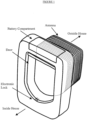
- FIG. 1 shows a drawing of an embodiment of the invention.
- the pet door comprises a frame that supports the door and a battery compartment, together with the electronic locking mechanism.
- the frame mounts on the inside of the house, for example on a door or wall.
- a tunnel protrudes from the frame through to the outside of the house and will often be surrounded by a separate cosmetic frame mounted outside (not shown).
- the low loss antenna is made up from a single layer of wire turns, wrapped around the tunnel wall.
- This embodiment uses 38 turns of Litz wire; the Litz wire comprises 42 strands of 36 AWG size copper.
- the total winding width of the coil is 50mm.
- tunnel there may be an additional cover for the tunnel to enclose the antenna, for protection and/or cosmetic appeal.
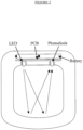
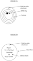
- Figure 2 shows a diagram of the pet door from a face-on position.
- the batteries, PCB and optical components of the proximity detector are indicated.
- the proximity detector comprises an infrared LED and photodiode situated on opposite sides of the top surface of the tunnel, through which the animal passes. Light emitted by the LED is incident on the bottom of the tunnel and is reflected back up in a diffuse manner. Two different possible light paths are shown, illustrating that a large proportion of the access hole is covered by light undergoing the single reflection from the tunnel bottom.
- the bottom of the tunnel is shown curved in this embodiment, however because the reflection is diffuse, the precise shape of the tunnel is not critical and a flat-bottomed tunnel would be equally applicable.
- the texture of the tunnel may optionally be patterned to promote a diffuse reflection, for example through a matt finish.
- the tunnel shape may be shaped to focus the light from the LED to the photodiode, in which case a specular reflection would also give good performance.
- the animal When the animal comes to enter the house, it puts its head into the tunnel and blocks some of the light paths between the LED and photodiode. This reduces the measured intensity, and the proximity of the animal is registered. Note that the spatial separation of the LED and photodiode helps to eliminate a complication that could otherwise arise from a direct reflection from the animal. In the arrangement shown, when the animal's head is in the path of the light emitted by the LED, very little light will be scattered through the large angle required to hit the photodiode. Furthermore, the photodiode has low sensitivity at high angles, reducing the amplitude of any signal associated with a direct reflection to an even lower level.
- the shape of the openings in the top surface of the tunnel for the LED and photodiode may be designed to control their angular sensitivity. For example, recessing the LED and photodiode in the moulding will reduce there sensitivity to large angles, ensuring that the measured signal is a result of the reflection from the bottom surface, rather than any direct reflection from the animal, as described above. Furthermore, the moulding may be used to block any significant direct optical cross talk between the LED and photodiode. Such cross talk would not be blocked by the presence of the animal and would therefore simply serve to degrade the signal quality.
- the optical detector is required to operate in the presence of sunlight.
- an infrared LED and photodiode are used, where the photodiode has an optical filter to attenuate the effects of visible light.
- the photodiode has an optical filter to attenuate the effects of visible light.
- the invention is not limited to an infrared LED and photodiode; a similar pair that operate in the visible spectrum would also be an option provided the effects of sunlight are mitigated by any other measured taken.
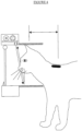
- Figure 3 shows the side-on perspective of the pet door, illustrating the position of the optical components, supporting PCB, and batteries. From this perspective the LED and photodiode overly each other, lying in the same plane.
- the PCB that supports the optical components also preferably supports the RFID reader electronics, and is connected to the antenna that surrounds the tunnel. Two possible light paths from the LED to the photodiode via a diffuse reflection from the bottom of the tunnel are shown.
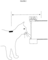
- Figure 4 shows the same side on perspective as figure 3 , this time including a drawing of a cat about to enter the house. As the animal enters the tunnel, some of the possible light paths are blocked, as shown. The drop in intensity may be measured and the presence of the animal registered.
- Figure 4 also illustrates a key advantage of the antenna arrangement. Because the door need only be locked to an animal entering the house, its position on this side of the door gives an effective increase in the range and reliability of the system. In order to enter the house the animal will touch the door with its head. Because the tag is situated behind the head of the animal, the arrangement shown reduces the antenna-tag separation. The relevant distance is indicated by a double-headed arrow.
- FIG. 5 shows the corresponding diagram for the animal leaving the house. It is clear that the chosen arrangement for the antenna increases the antenna-tag separation for this situation. This would reduce the effective range of the system on this side, however the door is not locked to the animal leaving the house and this is therefore of no consequence.
- the antenna arrangement effectively trades improved range for an animal entering the house for lower range leaving.
- the optical detector is likewise not designed to register an animal on the inside of the house, only the presence within the tunnel. Note that when the animal leaves the house then it will lead to a triggering of the optical detector when the door is open and the animal is halfway out.
- An optional sensor to determine whether the door is open or closed may be used to differentiate between the animal about to enter the house (door closed) or in the process of leaving (door open). Such a sensor would enable the RFID reader to be powered up only for an animal entering the house, saving any unnecessary battery drain with its operation on leaving the house.
- Figure 6 shows a drawing of the hinged door together with the components of an electronically controlled lock.
- the door is hinged at the top, forming a flap in the normal way for such a pet door.
- the directions of the outside and inside of the house are indicated with arrows.
- a latch is situated under the door and is hinged behind the door. The end of the latch is sloped in one direction, as shown. There is also a spring that pushes the latch up into the closed state.
- the latch has a post that sticks out to the side. This engages with a motor via a spiral shaped attachment. Rotation of the motor through an almost complete turn switches the latch from a locked state to an unlocked state.
- the latch is currently shown in its locked state. When an animal attempts to enter the house, the door is locked against the flat portion of the latch. However the door is free to open to the outside, allowing the animal to leave the house when it desires.
- the door is opened by the motor rotating anti-clockwise by an almost compete turn.
- the attachment between the motor and the post has a spiral-like shape, such that its rotation gradually pushes the post downwards. This in turn leads to the end of the latch depressing, moving it away from the position that blocks the door from opening inwards. The door is therefore now free to open inwards and outwards.
- the spiral shape attachment also has a shape that stops the rotation of the motor after almost one complete turn (a protrusion that hits against the post). When it comes to locking the door again, the motor is rotated in the reverse direction and the latch is pushed up to the locked position by the spring.
- the door When the door has been locked after allowing the animal entry into the house, it may be that the door remains open. For example the animal may be slow to enter the house and the latch switched to the locked position after a fixed amount of time. Once the animal fully enters the house, the door will swing down to the closed position. Here the sloped shape of the latch allows the door to depress the latch and move past it to its closed rest position. Once it has closed the latch is forced up by the spring to the locked position.
- the feature that allows this operation is that the latch is not fixed to the motor, rather it is in pressure contact with the motor attachment. When the latch is depressed by the door closing, the post breaks contact with the motor attachment, coming back into contact after the door comes to rest in its closed position.
- a spring is used to push the latch upward to rest in the locked position, provided the motor is switched to the clockwise position.
- An alternative is to place a weight the other side of the pivot that will be pulled down by gravity. Provided this is of sufficient mass to counterbalance the weight of the latch, it will force the latch position in the same direction as the spring shown. This may lead to a cost saving, either through the elimination of the spring component, or by making assembly of the unit simpler and quicker.
- the latch arrangement shown is stable both in the locked and unlocked states.
- the controlling electronics simply has to send a current through the motor in the right direction to switch the latch from closed to open, and vice versa.
- Figure 7 shows an RFID equipped identity tag that may be mounted to the animal's collar in place of the sub-dermal implant.
- an RFID tag does not benefit from the features of the sub-dermal implant (no collar needed, tag cannot be lost, etc) it may be a convenient alternative since it may be used without a visit to a vet to insert a chip. If the animal already wears a collar then it will usually have a visible identity tag, in which case combining this with the RFID tag avoids the need to attach two separate items to the collar.
- the identity tag is usually metal, which if in close contact to the RFID tag may alter its properties. In particular, the metal tag may change the resonant frequency and Q of the tag, leading to unreliable operation.
- RFID tags with form factors suitable for animal identity tags are well known in the art.
- Figure 7A shows a typical tag, where a spiral shaped printed antenna is shown on a circular disk.
- the RFID tags generally have a plastic outer casing, or some other non-metallic material, in order to avoid influencing the tag properties.
- this material is likely to be less robust than a conventional metal tag, and be prone to either breaking off or scratching of the information marked on the surface.
- a metal identity disk is attached to the front of the RFID tag.
- a typical identity disk is shown in figure 7B
- the combined RFID equipped identity tag is shown in figure 7C .
- Such a combination will have good robustness to either breaking or scratching, comparable to a conventional identity tag. This arrangement would not be considered with a conventional reader, because of the detrimental effect of the metal on the antenna.
- the reader employed in the pet door is designed for use with typical sub-dermal RFID tags. These have a small size and a correspondingly low coupling constant to the reader antenna; this requires very a high performance reader. However, when operating with the collar mounted RFID tag, the task of reading is made significantly easier by the greater coupling constant associated with the tag dimensions.
- the reader has a sensitivity that is much greater than the minimum required for reliable operation. As a result the system will not only operate with high levels of misalignment of the collar mounted tag, but may also tolerate the adverse affect of the metal identity tag on the RFID tag.
- a further aspect of the tag that may improve the reliability of the system is the material composition of the identity tag.
- a ferromagnetic material such as steel or ferrite will generally increase the inductance of an antenna, lowering its resonant frequency.
- Such a construction may be achieved through the proper choice of metal or alloy for the disk.
- a layered construction of ferromagnetic and conductive materials may be employed.
- a further alternative is to design the tag antenna to operate in combination with the identity tag, such that the target resonant frequency and/or Q results only when the metal tag comes into close proximity.
Landscapes
- Engineering & Computer Science (AREA)
- Civil Engineering (AREA)
- Structural Engineering (AREA)
- Physics & Mathematics (AREA)
- General Physics & Mathematics (AREA)
- Lock And Its Accessories (AREA)
- Details Of Aerials (AREA)
- Support Of Aerials (AREA)
Applications Claiming Priority (4)
| Application Number | Priority Date | Filing Date | Title |
|---|---|---|---|
| GB0619489A GB0619489D0 (en) | 2006-10-03 | 2006-10-03 | RFID pet door |
| EP07804445.0A EP2080172B1 (de) | 2006-10-03 | 2007-09-13 | Rfid-pet-klappe |
| PCT/GB2007/050540 WO2008041016A1 (en) | 2006-10-03 | 2007-09-13 | Rfid pet door |
| EP15181642.8A EP2983141B1 (de) | 2006-10-03 | 2007-09-13 | Rfid-haustierklappe |
Related Parent Applications (3)
| Application Number | Title | Priority Date | Filing Date |
|---|---|---|---|
| EP07804445.0A Division EP2080172B1 (de) | 2006-10-03 | 2007-09-13 | Rfid-pet-klappe |
| EP15181642.8A Division EP2983141B1 (de) | 2006-10-03 | 2007-09-13 | Rfid-haustierklappe |
| EP15181642.8A Division-Into EP2983141B1 (de) | 2006-10-03 | 2007-09-13 | Rfid-haustierklappe |
Publications (2)
| Publication Number | Publication Date |
|---|---|
| EP4303391A2 true EP4303391A2 (de) | 2024-01-10 |
| EP4303391A3 EP4303391A3 (de) | 2024-03-13 |
Family
ID=37435135
Family Applications (3)
| Application Number | Title | Priority Date | Filing Date |
|---|---|---|---|
| EP15181642.8A Active EP2983141B1 (de) | 2006-10-03 | 2007-09-13 | Rfid-haustierklappe |
| EP07804445.0A Active EP2080172B1 (de) | 2006-10-03 | 2007-09-13 | Rfid-pet-klappe |
| EP23209022.5A Pending EP4303391A3 (de) | 2006-10-03 | 2007-09-13 | Rfid-haustierklappe |
Family Applications Before (2)
| Application Number | Title | Priority Date | Filing Date |
|---|---|---|---|
| EP15181642.8A Active EP2983141B1 (de) | 2006-10-03 | 2007-09-13 | Rfid-haustierklappe |
| EP07804445.0A Active EP2080172B1 (de) | 2006-10-03 | 2007-09-13 | Rfid-pet-klappe |
Country Status (5)
| Country | Link |
|---|---|
| US (2) | US8240085B2 (de) |
| EP (3) | EP2983141B1 (de) |
| ES (1) | ES2979022T3 (de) |
| GB (1) | GB0619489D0 (de) |
| WO (1) | WO2008041016A1 (de) |
Families Citing this family (67)
| Publication number | Priority date | Publication date | Assignee | Title |
|---|---|---|---|---|
| GB0525623D0 (en) | 2005-12-16 | 2006-01-25 | Hill Nicholas P R | RFID reader |
| GB0619489D0 (en) * | 2006-10-03 | 2006-11-08 | Hill Nicholas P R | RFID pet door |
| GB0709575D0 (en) | 2007-05-18 | 2007-06-27 | Cambridge Resonant Technologie | RFIC Iterrogator |
| GB0800819D0 (en) | 2008-01-17 | 2008-02-27 | Cambridge Resonant Technologie | Improved rfid pet door |
| US20090188435A1 (en) * | 2008-01-25 | 2009-07-30 | Hale Jr Seymour B | Apparatus and methods for securing pet doors |
| DE202009002677U1 (de) * | 2009-03-05 | 2010-08-12 | Feldberglicht Gmbh | Zugangsvorrichtung für Tiere |
| EP2411939B1 (de) * | 2009-03-23 | 2015-09-16 | Satyatek Sa | System und verfahren zum lesen eines oder mehrerer rfid-etikette in einer metallkassette mit einem antikollisionsprotokoll |
| US8154382B2 (en) | 2009-05-13 | 2012-04-10 | Crucs Holdings, Llc | Systems, methods, and kits for automatically activating a garage door opener |
| US8619141B2 (en) * | 2009-12-22 | 2013-12-31 | Deere & Company | Portal management |
| US9284773B1 (en) * | 2010-09-28 | 2016-03-15 | Marlene E. Fridley | Locking pet door system |
| GB201115718D0 (en) | 2011-09-12 | 2011-10-26 | Sureflap Ltd | Selective pet doors |
| US11470814B2 (en) | 2011-12-05 | 2022-10-18 | Radio Systems Corporation | Piezoelectric detection coupling of a bark collar |
| US10674709B2 (en) | 2011-12-05 | 2020-06-09 | Radio Systems Corporation | Piezoelectric detection coupling of a bark collar |
| US11553692B2 (en) | 2011-12-05 | 2023-01-17 | Radio Systems Corporation | Piezoelectric detection coupling of a bark collar |
| GB2498346B (en) | 2012-01-10 | 2016-01-06 | Pet Mate Ltd | Pet door systems and methods of operation thereof |
| US8917172B2 (en) * | 2012-02-15 | 2014-12-23 | Epc4Roi Limited Partnership | Wireless pet barrier using RFID |
| US8826594B2 (en) * | 2012-05-15 | 2014-09-09 | Radio Systems Corporation | Pet door with locking flaps |
| US9508206B2 (en) | 2012-08-16 | 2016-11-29 | Schlage Lock Company Llc | Usage of GPS on door security |
| US9157269B2 (en) * | 2012-10-03 | 2015-10-13 | Richard Brown | Automatic pet door controlled by smart phone |
| US8595976B1 (en) * | 2013-02-08 | 2013-12-03 | Henry E. Solowiej | Gyro-stabilized automatic pet door |
| US8967085B2 (en) * | 2013-03-15 | 2015-03-03 | Radio Systems Corporation | Electronic pet gate |
| US10228447B2 (en) | 2013-03-15 | 2019-03-12 | Radio Systems Corporation | Integrated apparatus and method to combine a wireless fence collar with GPS tracking capability |
| US9024759B2 (en) | 2013-03-15 | 2015-05-05 | Kwikset Corporation | Wireless lockset with integrated antenna, touch activation, and light communication method |
| US8854215B1 (en) | 2013-03-15 | 2014-10-07 | Brian Ellis | Automated pet door |
| US8803657B1 (en) | 2013-07-25 | 2014-08-12 | Fawzi Q. M. A. O. A. Behbehani | RFID-mechanical dual-mode entry key |
| US9345231B2 (en) * | 2013-11-26 | 2016-05-24 | Vet Innovations, Llc | Selective access control apparatus for animals using electronic recognition |
| GB2538637B (en) | 2013-12-03 | 2020-02-12 | Radio Systems Corp | Threshold barrier system |
| USD743051S1 (en) * | 2013-12-09 | 2015-11-10 | Dean Edward Swensson | Gate |
| GB201409372D0 (en) * | 2014-05-27 | 2014-07-09 | Pet Mate Ltd | Pet door control system |
| GB2533542A (en) * | 2014-05-27 | 2016-06-29 | Pet Mate Ltd | Pet door control system |
| US9651606B2 (en) * | 2014-06-16 | 2017-05-16 | Fluke Corporation | Fluorescent lamp testing device |
| USD897559S1 (en) | 2014-12-31 | 2020-09-29 | James Taylor | Pet door assembly |
| US10231440B2 (en) | 2015-06-16 | 2019-03-19 | Radio Systems Corporation | RF beacon proximity determination enhancement |
| US10645908B2 (en) | 2015-06-16 | 2020-05-12 | Radio Systems Corporation | Systems and methods for providing a sound masking environment |
| US9916485B1 (en) * | 2015-09-09 | 2018-03-13 | Cpg Technologies, Llc | Method of managing objects using an electromagnetic guided surface waves over a terrestrial medium |
| US10223850B2 (en) * | 2015-10-31 | 2019-03-05 | Disney Enterprises, Inc. | High-Q and over-coupled near-field RFID reader antenna for improved tag read range |
| US10102697B2 (en) * | 2015-10-31 | 2018-10-16 | Disney Enterprises, Inc. | High-Q and over-coupled near-field RFID reader antenna for improved tag read range |
| USD800397S1 (en) * | 2016-02-24 | 2017-10-17 | Dalchand Harripersad | Enclosure |
| CA3017635A1 (en) | 2016-03-22 | 2017-09-28 | Spectrum Brands, Inc. | Garage door opener with touch sensor authentication |
| US10268220B2 (en) | 2016-07-14 | 2019-04-23 | Radio Systems Corporation | Apparatus, systems and methods for generating voltage excitation waveforms |
| US10619389B2 (en) * | 2016-12-20 | 2020-04-14 | Radio Systems Corporation | Pet door having insulating flap |
| GB2573249B (en) | 2017-02-27 | 2022-05-04 | Radio Systems Corp | Threshold barrier system |
| US10332370B2 (en) * | 2017-04-04 | 2019-06-25 | Sensormatic Electronics, LLC | System and method for energy saving on access control products |
| US10941611B2 (en) | 2017-08-18 | 2021-03-09 | Radio Systems Corporation | Pet door |
| AU2018319010A1 (en) | 2017-08-18 | 2020-03-05 | Radio Systems Corporation | Electronic pet door |
| US11394196B2 (en) | 2017-11-10 | 2022-07-19 | Radio Systems Corporation | Interactive application to protect pet containment systems from external surge damage |
| US10842128B2 (en) | 2017-12-12 | 2020-11-24 | Radio Systems Corporation | Method and apparatus for applying, monitoring, and adjusting a stimulus to a pet |
| US10986813B2 (en) | 2017-12-12 | 2021-04-27 | Radio Systems Corporation | Method and apparatus for applying, monitoring, and adjusting a stimulus to a pet |
| US10514439B2 (en) | 2017-12-15 | 2019-12-24 | Radio Systems Corporation | Location based wireless pet containment system using single base unit |
| US11372077B2 (en) | 2017-12-15 | 2022-06-28 | Radio Systems Corporation | Location based wireless pet containment system using single base unit |
| US11450158B2 (en) | 2018-01-05 | 2022-09-20 | Spectrum Brands, Inc. | Touch isolated electronic lock |
| CN110060394B (zh) * | 2019-03-30 | 2021-09-03 | 孟琦 | 一种物联网小区智慧门禁系统 |
| CN110219571A (zh) * | 2019-06-19 | 2019-09-10 | 中国计量大学 | 一种基于电阻应变片和rfid标签双重检测的宠物门 |
| US12060743B2 (en) | 2019-06-25 | 2024-08-13 | Smartec Products LLC | Methods and apparatus for pet doors |
| CA3119791A1 (en) * | 2019-06-25 | 2020-12-30 | Smartec Products LLC | Methods and apparatus for pet doors |
| US12359492B2 (en) | 2019-06-25 | 2025-07-15 | Smartec Products LLC | Methods and apparatus for pet doors |
| US11238889B2 (en) | 2019-07-25 | 2022-02-01 | Radio Systems Corporation | Systems and methods for remote multi-directional bark deterrence |
| CN111710063A (zh) * | 2020-05-14 | 2020-09-25 | 特斯联科技集团有限公司 | 写字楼智能门禁 |
| US11490597B2 (en) | 2020-07-04 | 2022-11-08 | Radio Systems Corporation | Systems, methods, and apparatus for establishing keep out zones within wireless containment regions |
| US20230035034A1 (en) * | 2021-07-31 | 2023-02-02 | Yongji CHEN | Automatic animal door system |
| US12421792B2 (en) * | 2021-09-02 | 2025-09-23 | Radio Systems Corporation | Pet door |
| DE102022116065B4 (de) | 2022-06-28 | 2024-05-23 | Thomas Prosser | Ergänzendes Zugangskontrollsystem für eine RFID-gesteuerte Katzenklappe und Verfahren zur ergänzenden Kontrolle des Zugangs durch eine RFID-gesteuerte Katzenklappe |
| USD1011556S1 (en) * | 2023-08-04 | 2024-01-16 | Xiongjie Yang | Pet door |
| USD1080915S1 (en) * | 2023-11-03 | 2025-06-24 | Radio Systems Corporation | Pet door |
| USD1098491S1 (en) * | 2024-04-11 | 2025-10-14 | Mingchang Zhou | Pet door |
| USD1093655S1 (en) * | 2024-04-29 | 2025-09-16 | Shenzhen Fengsheng Pet Products Co., Ltd | Screen door |
| USD1093656S1 (en) * | 2024-05-09 | 2025-09-16 | Shenzhen Fengsheng Pet Products Co., Ltd. | Footprint screen pet door |
Citations (1)
| Publication number | Priority date | Publication date | Assignee | Title |
|---|---|---|---|---|
| GB2305211A (en) | 1995-09-07 | 1997-04-02 | Reilor Ltd | Security locking circuit |
Family Cites Families (50)
| Publication number | Priority date | Publication date | Assignee | Title |
|---|---|---|---|---|
| US2282759A (en) * | 1940-08-03 | 1942-05-12 | Gavitt Mfg Company | Antenna loop |
| US4022263A (en) * | 1976-09-02 | 1977-05-10 | Beckett Richard W | Magnetically actuated cat door |
| GB1588673A (en) * | 1978-03-08 | 1981-04-29 | Paul B | Cat flap lock |
| US4216743A (en) * | 1978-05-30 | 1980-08-12 | Cohen Robert E | Magnetically unlocked pet door |
| GB2119431B (en) | 1982-04-23 | 1985-05-01 | Reilor Ltd | Control circuit for a door |
| US6072402A (en) * | 1992-01-09 | 2000-06-06 | Slc Technologies, Inc. | Secure entry system with radio communications |
| GB2223257B (en) * | 1988-07-16 | 1992-01-22 | Pet Mate Ltd | Improved electromagnetically controlled cat door |
| GB2236135B (en) * | 1989-09-22 | 1993-08-25 | Pet Mate Ltd | Improvements in cat doors |
| BR9207033A (pt) * | 1992-01-09 | 1995-12-05 | Supra Prod Inc | Sistema de entrada de segurança com radiocomunicação |
| JPH05235626A (ja) * | 1992-02-25 | 1993-09-10 | Smk Corp | 金属製ドアにアンテナを取り付ける方法 |
| GB9225879D0 (en) * | 1992-12-11 | 1993-02-03 | Reilor Holdings Ltd | Improved pet door |
| GB9507167D0 (en) * | 1995-04-06 | 1995-05-31 | Reilor Ltd | Improved pet door |
| GB2317226B (en) | 1996-09-17 | 1998-07-22 | Graham Harold Haslip | Cat-flap entry validation system |
| US5813364A (en) * | 1997-05-09 | 1998-09-29 | Harrison; Charles | Automatic pet door housing |
| JPH1141152A (ja) * | 1997-07-17 | 1999-02-12 | Kokusai Electric Co Ltd | アンテナ |
| GB2334067B (en) * | 1998-02-09 | 2002-07-17 | Reilor Ltd | Pet door |
| WO1999067492A1 (en) | 1998-06-22 | 1999-12-29 | Glow Dog, Inc. | Pet door |
| US5992096A (en) * | 1998-10-19 | 1999-11-30 | Pooch Pass, Inc. | Controllable pet access system |
| US6297739B1 (en) * | 2000-03-20 | 2001-10-02 | David K. Small | System and method for providing access to selected animals to a secured enclosure |
| FR2807462B1 (fr) | 2000-04-06 | 2003-06-20 | Valeo Electronique | Systeme de deverouillage ou d'ouverture d'ouvrant(s) de vehicule, notamment automobile, en particulier systeme d'ouverture de coffre |
| GB2361735B (en) * | 2000-04-28 | 2002-02-27 | Pet Mate Ltd | Improved electro-magnetically controlled pet door |
| SE520984C2 (sv) * | 2000-08-10 | 2003-09-16 | Volvo Technology Corp | Metod och system för att låsa upp ett föremål |
| GB2376977B (en) * | 2001-06-25 | 2004-10-20 | Roger Duerden | Selective entry pet door controlled by sub-dermal identification device |
| GB2381180B (en) | 2001-10-24 | 2004-12-22 | David Chamberlain | Animal access system |
| US6681524B1 (en) * | 2002-08-29 | 2004-01-27 | Richard Arthur Tillson | Insulated, weatherproof, and lockable pet door |
| GB2393245B (en) | 2002-09-19 | 2005-12-21 | Reilor Holdings Ltd | Automatic pet door |
| US20040100386A1 (en) * | 2002-11-22 | 2004-05-27 | Tendler Robert K. | Animal selective pet door |
| US6944990B2 (en) * | 2002-12-17 | 2005-09-20 | Noyes Crosby S | Window mounted automatic pet door |
| US7209043B2 (en) * | 2003-12-15 | 2007-04-24 | Anderson Ii James Austin | Sensing system for pet controllable access |
| US8272053B2 (en) * | 2003-12-18 | 2012-09-18 | Honeywell International Inc. | Physical security management system |
| US6966147B2 (en) * | 2004-03-09 | 2005-11-22 | Solowiej Henry E | Automatic pet door |
| US20050274463A1 (en) * | 2004-06-15 | 2005-12-15 | Kent Becker | Pet door and method of operation |
| US7339476B2 (en) * | 2004-11-10 | 2008-03-04 | Rockwell Automation Technologies, Inc. | Systems and methods that integrate radio frequency identification (RFID) technology with industrial controllers |
| US7551081B2 (en) * | 2004-11-10 | 2009-06-23 | Rockwell Automation Technologies, Inc. | Systems and methods that integrate radio frequency identification (RFID) technology with agent-based control systems |
| WO2006058148A2 (en) * | 2004-11-23 | 2006-06-01 | Classy Custom Inc. | Pet door having removable decorative frames |
| US7458336B2 (en) * | 2005-05-07 | 2008-12-02 | Philip Stephen Eu | Animal identification and entry control system for feeding purposes |
| US7583931B2 (en) * | 2005-05-07 | 2009-09-01 | Philip Stephen Eu | Animal identification and entry control system |
| US20070051317A1 (en) * | 2005-09-08 | 2007-03-08 | Michael Bruner | Systems and methods for providing selective access to a consumable |
| US7446662B1 (en) * | 2005-09-26 | 2008-11-04 | Rockwell Automation Technologies, Inc. | Intelligent RFID tag for magnetic field mapping |
| US8025227B2 (en) * | 2005-09-30 | 2011-09-27 | Rockwell Automation Technologies, Inc. | Access to distributed databases via pointer stored in RFID tag |
| WO2007047663A2 (en) * | 2005-10-17 | 2007-04-26 | Ideal Pet Products, Inc. | Pet door with built in alarm |
| US8232860B2 (en) * | 2005-10-21 | 2012-07-31 | Honeywell International Inc. | RFID reader for facility access control and authorization |
| GB2431431B (en) * | 2005-10-22 | 2010-05-19 | Pet Mate Ltd | Pet door |
| GB0525623D0 (en) | 2005-12-16 | 2006-01-25 | Hill Nicholas P R | RFID reader |
| GB2432999B (en) | 2005-12-16 | 2007-11-28 | Nicholas Patrick Roland Hill | RF tag detection |
| GB2433381B (en) | 2005-12-16 | 2008-03-05 | Nicholas Patrick Roland Hill | Resonant circuits |
| CA2648114C (en) * | 2006-04-11 | 2016-03-15 | Joseph V. Ambrose | Spring-assisted mechanism for raising and lowering a load |
| GB0619489D0 (en) * | 2006-10-03 | 2006-11-08 | Hill Nicholas P R | RFID pet door |
| US7852224B1 (en) * | 2008-01-09 | 2010-12-14 | Keehn Sr Donn A | Door announcement system |
| US8286591B2 (en) * | 2009-05-05 | 2012-10-16 | Casey Moffett-Chaney | Assemblies for allowing pet access through a panel |
-
2006
- 2006-10-03 GB GB0619489A patent/GB0619489D0/en not_active Ceased
-
2007
- 2007-09-13 EP EP15181642.8A patent/EP2983141B1/de active Active
- 2007-09-13 EP EP07804445.0A patent/EP2080172B1/de active Active
- 2007-09-13 US US12/443,773 patent/US8240085B2/en active Active
- 2007-09-13 WO PCT/GB2007/050540 patent/WO2008041016A1/en not_active Ceased
- 2007-09-13 EP EP23209022.5A patent/EP4303391A3/de active Pending
- 2007-09-13 ES ES15181642T patent/ES2979022T3/es active Active
-
2012
- 2012-07-11 US US13/546,821 patent/US8539715B2/en active Active
Patent Citations (1)
| Publication number | Priority date | Publication date | Assignee | Title |
|---|---|---|---|---|
| GB2305211A (en) | 1995-09-07 | 1997-04-02 | Reilor Ltd | Security locking circuit |
Also Published As
| Publication number | Publication date |
|---|---|
| GB0619489D0 (en) | 2006-11-08 |
| EP2080172B1 (de) | 2015-12-30 |
| US20120272696A1 (en) | 2012-11-01 |
| EP2080172A1 (de) | 2009-07-22 |
| EP2983141A1 (de) | 2016-02-10 |
| EP4303391A3 (de) | 2024-03-13 |
| US8240085B2 (en) | 2012-08-14 |
| EP2983141B1 (de) | 2024-04-10 |
| WO2008041016A1 (en) | 2008-04-10 |
| ES2979022T3 (es) | 2024-09-23 |
| US8539715B2 (en) | 2013-09-24 |
| US20100126071A1 (en) | 2010-05-27 |
Similar Documents
| Publication | Publication Date | Title |
|---|---|---|
| EP2983141B1 (de) | Rfid-haustierklappe | |
| CA2931621C (en) | Access control for animals using electronic recognition | |
| US7446644B2 (en) | Universal hands free key and lock system | |
| CN102906360B (zh) | 无缝认证系统 | |
| EP3815065B1 (de) | Sicherheitsalarmsystem mit einem rfid-etikett | |
| US20050252622A1 (en) | Automatic pet door | |
| US20050083174A1 (en) | Object sensor and controller | |
| US20080072843A1 (en) | Access device for pets | |
| US20020190126A1 (en) | Elecronic key reader | |
| KR20120073794A (ko) | Rfid 차폐실을 이용한 물류 관리 시스템 및 관리 방법 | |
| JP3808796B2 (ja) | 自動ドア装置 | |
| JP2019094727A (ja) | 扉制御システム | |
| US20020113747A1 (en) | Transmitter and receiver coil | |
| KR101249940B1 (ko) | 출입문 관리장치 및 방법 | |
| JP2019073922A (ja) | 扉制御システム | |
| CN211375672U (zh) | 一种门禁读卡器外壳及读卡器 | |
| CN207739830U (zh) | 智能设备及其开关门控制系统 | |
| CN222784917U (zh) | 闸机回收手环机构 | |
| JP7609586B2 (ja) | 扉制御システム | |
| GB2483551A (en) | Animal access system | |
| CN120759492A (zh) | 一种电磁锁装置 | |
| JP2005092638A (ja) | 非接触icカードリーダ | |
| WO1999067492A9 (en) | Pet door | |
| CN118038574A (zh) | 出入状态的检测方法、装置和电子设备 | |
| GB2498257A (en) | Pet presence alert system |
Legal Events
| Date | Code | Title | Description |
|---|---|---|---|
| PUAI | Public reference made under article 153(3) epc to a published international application that has entered the european phase |
Free format text: ORIGINAL CODE: 0009012 |
|
| STAA | Information on the status of an ep patent application or granted ep patent |
Free format text: STATUS: REQUEST FOR EXAMINATION WAS MADE |
|
| 17P | Request for examination filed |
Effective date: 20231110 |
|
| AC | Divisional application: reference to earlier application |
Ref document number: 2080172 Country of ref document: EP Kind code of ref document: P Ref document number: 2983141 Country of ref document: EP Kind code of ref document: P |
|
| AK | Designated contracting states |
Kind code of ref document: A2 Designated state(s): AT BE BG CH CY CZ DE DK EE ES FI FR GB GR HU IE IS IT LI LT LU LV MC MT NL PL PT RO SE SI SK TR |
|
| REG | Reference to a national code |
Ref country code: DE Ref legal event code: R079 Free format text: PREVIOUS MAIN CLASS: E06B0007000000 Ipc: G07C0009200000 |
|
| PUAL | Search report despatched |
Free format text: ORIGINAL CODE: 0009013 |
|
| AK | Designated contracting states |
Kind code of ref document: A3 Designated state(s): AT BE BG CH CY CZ DE DK EE ES FI FR GB GR HU IE IS IT LI LT LU LV MC MT NL PL PT RO SE SI SK TR |
|
| RIC1 | Information provided on ipc code assigned before grant |
Ipc: E06B 7/00 20060101ALI20240206BHEP Ipc: G07C 9/20 20200101AFI20240206BHEP |
|
| REG | Reference to a national code |
Ref country code: DE Ref legal event code: R079 Free format text: PREVIOUS MAIN CLASS: G07C0009200000 Ipc: G07C0009280000 |
|
| GRAP | Despatch of communication of intention to grant a patent |
Free format text: ORIGINAL CODE: EPIDOSNIGR1 |
|
| STAA | Information on the status of an ep patent application or granted ep patent |
Free format text: STATUS: GRANT OF PATENT IS INTENDED |
|
| RIC1 | Information provided on ipc code assigned before grant |
Ipc: G07C 9/28 20200101AFI20251025BHEP Ipc: E06B 7/32 20060101ALI20251025BHEP |
|
| INTG | Intention to grant announced |
Effective date: 20251112 |
|
| RAP3 | Party data changed (applicant data changed or rights of an application transferred) |
Owner name: SUREFLAP LTD |
|
| GRAS | Grant fee paid |
Free format text: ORIGINAL CODE: EPIDOSNIGR3 |
|
| GRAA | (expected) grant |
Free format text: ORIGINAL CODE: 0009210 |
|
| STAA | Information on the status of an ep patent application or granted ep patent |
Free format text: STATUS: THE PATENT HAS BEEN GRANTED |