EP4303041A1 - Dreipunkt-querlenker - Google Patents
Dreipunkt-querlenker Download PDFInfo
- Publication number
- EP4303041A1 EP4303041A1 EP23180870.0A EP23180870A EP4303041A1 EP 4303041 A1 EP4303041 A1 EP 4303041A1 EP 23180870 A EP23180870 A EP 23180870A EP 4303041 A1 EP4303041 A1 EP 4303041A1
- Authority
- EP
- European Patent Office
- Prior art keywords
- wishbone
- shaped
- connection points
- point
- base body
- Prior art date
- Legal status (The legal status is an assumption and is not a legal conclusion. Google has not performed a legal analysis and makes no representation as to the accuracy of the status listed.)
- Granted
Links
Images

Classifications
-
- B—PERFORMING OPERATIONS; TRANSPORTING
- B60—VEHICLES IN GENERAL
- B60G—VEHICLE SUSPENSION ARRANGEMENTS
- B60G7/00—Pivoted suspension arms; Accessories thereof
- B60G7/001—Suspension arms, e.g. constructional features
-
- B—PERFORMING OPERATIONS; TRANSPORTING
- B60—VEHICLES IN GENERAL
- B60G—VEHICLE SUSPENSION ARRANGEMENTS
- B60G2206/00—Indexing codes related to the manufacturing of suspensions: constructional features, the materials used, procedures or tools
- B60G2206/01—Constructional features of suspension elements, e.g. arms, dampers, springs
- B60G2206/017—Constructional features of suspension elements, e.g. arms, dampers, springs forming an eye for the bushing
-
- B—PERFORMING OPERATIONS; TRANSPORTING
- B60—VEHICLES IN GENERAL
- B60G—VEHICLE SUSPENSION ARRANGEMENTS
- B60G2206/00—Indexing codes related to the manufacturing of suspensions: constructional features, the materials used, procedures or tools
- B60G2206/01—Constructional features of suspension elements, e.g. arms, dampers, springs
- B60G2206/10—Constructional features of arms
- B60G2206/124—Constructional features of arms the arm having triangular or Y-shape, e.g. wishbone
-
- B—PERFORMING OPERATIONS; TRANSPORTING
- B60—VEHICLES IN GENERAL
- B60G—VEHICLE SUSPENSION ARRANGEMENTS
- B60G2206/00—Indexing codes related to the manufacturing of suspensions: constructional features, the materials used, procedures or tools
- B60G2206/01—Constructional features of suspension elements, e.g. arms, dampers, springs
- B60G2206/10—Constructional features of arms
- B60G2206/14—Constructional features of arms the arm forming a U-shaped recess for fitting a bush
- B60G2206/141—The recess being integrally or seamlessly formed
-
- B—PERFORMING OPERATIONS; TRANSPORTING
- B60—VEHICLES IN GENERAL
- B60G—VEHICLE SUSPENSION ARRANGEMENTS
- B60G2206/00—Indexing codes related to the manufacturing of suspensions: constructional features, the materials used, procedures or tools
- B60G2206/01—Constructional features of suspension elements, e.g. arms, dampers, springs
- B60G2206/10—Constructional features of arms
- B60G2206/16—Constructional features of arms the arm having a U profile and/or made of a plate
-
- B—PERFORMING OPERATIONS; TRANSPORTING
- B60—VEHICLES IN GENERAL
- B60G—VEHICLE SUSPENSION ARRANGEMENTS
- B60G2206/00—Indexing codes related to the manufacturing of suspensions: constructional features, the materials used, procedures or tools
- B60G2206/01—Constructional features of suspension elements, e.g. arms, dampers, springs
- B60G2206/70—Materials used in suspensions
- B60G2206/72—Steel
- B60G2206/722—Plates
-
- B—PERFORMING OPERATIONS; TRANSPORTING
- B60—VEHICLES IN GENERAL
- B60G—VEHICLE SUSPENSION ARRANGEMENTS
- B60G2206/00—Indexing codes related to the manufacturing of suspensions: constructional features, the materials used, procedures or tools
- B60G2206/01—Constructional features of suspension elements, e.g. arms, dampers, springs
- B60G2206/80—Manufacturing procedures
- B60G2206/81—Shaping
- B60G2206/8102—Shaping by stamping
Definitions
- the present invention relates to a three-point wishbone according to the features in the preamble of claim 1.
- Car bodies or self-supporting bodies are used in automotive technology.
- the wheels are connected to the bodies or axles or axle supports via handlebars or wishbones.
- Such links are known as shell components, in particular as sheet metal components made of a steel material.
- Y-shaped configurations for three-point wishbones are also known.
- a wishbone should be designed to be as torsionally rigid as possible in order to optimally support the kinematics during compression and rebound of the wheel.
- the object of the present invention is to provide a wishbone which is improved in terms of the manufacturing variant and the possibility of arrangement in the motor vehicle as well as the influence on the deflection and rebound processes of the wheel.
- the three-point wishbone for a motor vehicle is manufactured as a single-shell, in particular one-piece, material-formed sheet metal component. It has a Y-shaped base body.
- the three-point wishbone is made from a steel material as a formed component. Preferred wall thicknesses are between 1 mm and 5 mm, in particular between 3 mm and 4 mm.
- the three-point wishbone has three connection points.
- a connection point is formed on the wheel carrier side.
- Two connection points are formed on the axle support side or the motor vehicle side.
- each connection point i.e. all connection points, is formed from two opposite collar openings to accommodate a respective rubber-metal bearing.
- a collar opening is designed as a hole or opening, in particular a round opening, from which a collar extends.
- the respective receiving openings are preferably parallel to each other.
- the collars are oriented towards each other. Bearings are then inserted, in particular pressed, into the respective collar openings.
- These are particularly preferably rubber-metal bearings, in particular with an outer long sleeve.
- the cross member offers the possibility of being manufactured particularly cost-effectively as a single-shell, one-piece and uniform sheet metal forming component.
- Sheet metal forming component can be set to an already optimized adaptation to specified installation spaces. Because all connection points are also made in one piece and made from the same material, there are no coupling operations with other add-on parts, such as ball joints or similar. This saves production costs.
- a further advantage according to the invention is that at least one of the Y-shaped arms has a taper along its longitudinal course.
- a respective taper is preferably formed on both Y-shaped arms.
- the taper can be designed as a reduction in the geometric cross-sectional shape and/or a reduction in the cross-sectional area.
- the taper can alternatively or additionally be designed as a recess and therefore material removal.
- the recess is designed as a wave shape, particularly in the longitudinal course of the Y-shaped arm.
- the torsional rigidity of the arm in the area of the connection point is reduced.
- the torsional rigidity is particularly preferably reduced to a value of ⁇ 10 Nm/degree.
- the rigidity of the handlebar in particular a lateral rigidity of the handlebar, is particularly preferably increased to >50 kN/mm.
- the handlebar thus maintains the distance between the individual connection points in its longitudinal direction.
- the bearing points of the Y-shaped arms are arranged at an angle of 30 to 70 degrees, more precisely 35 to 60 degrees and particularly preferably 40 to 55 degrees, the Y-shaped arms can be formed in this way Twist your arms around their own axis without affecting the stiffness of the handlebars.
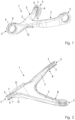
- FIG. 1 shows a three-point wishbone 1 according to the invention.
- the wishbone 1 has a Y-shaped base body 2 for this purpose. Two arms 3 protrude from this Y-shaped base body 2, which are also referred to as Y-shaped arms.
- a connection point is formed at each end.
- a wheel carrier-side connection point 4 is shown on the image plane on the left and two axle-carrier-side connection points 5 are shown on the image plane on the right.
- the connection points 5 themselves are formed by two opposite collar openings 6.
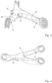
- the collar openings 6 themselves in turn have collars 7 that are directed inwards or point towards one another. This is also shown in Figure 2 , which is a bottom view of the wishbone according to Figure 1 represents.
- a respective bearing (not shown in detail) is pressed into the collar opening 6, especially a rubber-metal bearing.
- the forming tool can also be designed as a progressive composite tool or multi-stage pressing tool and the calibration can take place in one of the last or final stages.
- the base body and the arms are each C-shaped and U-shaped in their cross section.
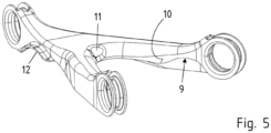
- FIG. 2 Another essential aspect of the invention is presented in Figure 2 , but also especially in Figures 3, 4 and 5 shown.
- the Y-shaped arms 3 have a constriction 8 in the direction of the connection points 5 on the axle carrier side.
- the constriction 8 is here in the form of a recess 9 of the Y-shaped arm 3. This reduces the torsional rigidity in the area of the connection points 5 on the axle carrier side.
- the respective Y-shaped arm 3 can rotate in the loading point about its own longitudinal axis, so that the wishbone 1 does not offer any resulting increased bending resistance during a compression or rebound process.
- a depression 11 is also formed on the Y-fork of the base body 2. Due to the depression 11, the Y-shaped arms 3 can move relative to one another during the compression or rebound process.
- Outwardly oriented projecting flanges 12 are also formed at the wheel carrier end. These flanges 12 stiffen the connection point 4 at the end on the wheel carrier side, so that greater rigidity is formed here in the area of the base body 2. Overall, this results in a sufficiently rigid three-point wishbone 1, which is made in one piece and made of the same material. At the same time, the cross member 1 inherently offers elasticity or ductility, but at the same time the wishbone is given ductility or flexibility due to its inherent rigidity.
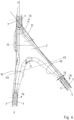
- Figure 6 shows a top view of the wishbone 1 according to the invention. It can be seen from this that the two connection points 5 on the axle carrier side are arranged or oriented at an angle ⁇ to one another. A respective extension of the central longitudinal section plane between the two collar openings 6 represents the extending orientation of the connection points 4, 5 for the bearings.
- Figure 7 shows a cross-sectional view along section line VII-VII Figure 6 .
- An opening direction 14 of the Y-shaped base body 2 or the Y-shaped arms 3 is oriented downwards in relation to the vertical direction.
- the wishbone 1 according to the invention is designed as a shell that is open on one side.
- An opening direction 14 is preferably arranged such that it runs transversely to a bearing axis, in particular transversely to all bearing axes 15, 16.
- all bearing axes 15, 16 of the connection points can lie in one plane. You can also see the C-shaped cross section of the arms.
- the depression 11 can also be seen at the fork point of the two arms.
- the depression 11 is embossed into the base body 2 oriented in the direction of the opening.
Landscapes
- Engineering & Computer Science (AREA)
- Mechanical Engineering (AREA)
- Vehicle Body Suspensions (AREA)
Abstract
Description
- Die vorliegende Erfindung betrifft einen Dreipunkt-Querlenker gemäß den Merkmalen im Oberbegriff von Anspruch 1.
- In der Kraftfahrzeugtechnik werden Karosserien bzw. selbsttragende Karosserien verwendet. Die Räder werden über Lenker bzw. Querlenker an die Karosserien bzw. Achsen oder Achsträger angeschlossen.
- Solche Lenker sind als Schalenbauteile bekannt, insbesondere als Blechumformbauteile aus einem Stahlwerkstoff.
- Insbesondere sind auch Y-förmige Konfigurationen für Dreipunkt-Querlenker bekannt.
- Ein Querlenker soll dabei möglichst verwindungssteif ausgebildet sein, um die Kinematik beim Ein- und Ausfedern des Rades optimal zu unterstützen.
- Aufgabe der vorliegenden Erfindung ist es, ein Querlenker aufzuzeigen, der in Bezug auf die Herstellungsvariante sowie auf die Möglichkeit der Anordnung in dem Kraftfahrzeug sowie der Beeinflussung des Einfederungs- und des Ausfederungsvorganges des Rades verbessert ist.
- Die zuvor genannte Aufgabe wird mit einem Dreipunkt-Querlenker für ein Kraftfahrzeug mit den Merkmalen im Anspruch 1 gelöst.
- Vorteilhafte Ausgestaltungsvarianten sind Gegenstand der abhängigen Ansprüche.
- Der Dreipunkt-Querlenker für ein Kraftfahrzeug ist als einschaliges, insbesondere einstückig und werkstoffeinheitliches Blechumformbauteil hergestellt. Er besitzt einen Y-förmigen Grundkörper. Der Dreipunkt-Querlenker ist aus einem Stahlwerkstoff als Umformbauteil hergestellt. Bevorzugte Wandstärken sind zwischen 1 mm und 5 mm, insbesondere zwischen 3 mm und 4 mm, gewählt.
- Der Dreipunkt-Querlenker weist drei Anbindungsstellen auf. Radträgerseitig ist eine Anbindungsstelle ausgebildet. Achsträgerseitig bzw. kraftfahrzeugseitig sind zwei Anbindungsstellen ausgebildet.
- Erfindungsgemäß zeichnet der Querlenker nunmehr dadurch aus, dass jede Anbindungsstelle, also alle Anbindungsstellen, aus zwei sich gegenüberliegenden Kragenöffnungen zur Aufnahme eines jeweiligen Gummimetalllagers ausgebildet sind. Eine Kragenöffnung ist als Loch bzw. Öffnung, insbesondere runde Öffnung, ausgebildet, von der aus sich ein Kragen erstreckt. Die jeweiligen Aufnahmeöffnungen liegen sich bevorzugt parallel gegenüber. Die Kragen sind aufeinander zu zeigend orientiert. In die jeweiligen Kragenöffnungen werden dann Lager eingeführt, insbesondere eingepresst. Hierbei handelt es sich besonders bevorzugt um Gummimetalllager, insbesondere mit einer äußeren Langerhülse.
- Erfindungsgemäß bietet der Querträger die Möglichkeit, dass als einschaliges und einstückiges und werkstoffeinheitliches Blechumformbauteil dieses besonders kostengünstig hergestellt werden kann. Gleichzeitig kann durch die Herstellung als Blechumformbauteil eine bereits optimierte Anpassung an vorgegebene Bauräume eingestellt werden. Dadurch, dass alle Anbindungsstellen einstückig und werkstoffeinheitlich ebenfalls mit hergestellt sind, fallen keine Koppeloperationen mit weiteren Anbauteilen, beispielsweise Kugelgelenken oder ähnlichem an. Dies spart Produktionskosten.
- Ein weiterer erfindungsgemäßer Vorteil ist darin begründet, dass mindestens einer der Y-förmigen Arme über seinen Längsverlauf eine Verjüngung aufweist. Bevorzugt sind an beiden Y-förmigen Armen eine jeweilige Verjüngung ausgebildet. Die Verjüngung kann dabei als Reduzierung der geometrischen Querschnittsform und/oder Reduzierung der Querschnittsfläche ausgebildet sein. Die Verjüngung kann alternativ oder ergänzend als Aussparung mithin Materialabtrag ausgebildet sein. Die Aussparung ist insbesondere im Längsverlauf des Y-förmiges Arms als Wellenform ausgebildet. Hierdurch ergibt sich erfindungsgemäß der Vorteil, dass der Querträger an sich verwindungssteif ausgebildet ist als Blechumformbauteil, insbesondere mit einem C- oder U-förmigen Querschnitt des Grundkörpers bzw. der Arme. Gleichzeitig wird jedoch aufgrund der Verjüngung erreicht, dass die Verdrehsteifigkeit des Armes im Bereich der Anbindungsstelle reduziert wird. Besonders bevorzugt wird die Verdrehsteifigkeit auf einen Wert von < 10 Nm/Grad reduziert. Beim Ein- und Ausfederungsvorgang kann somit an den beiden Anbindungsstellen achsträgerseitig sichergestellt werden, dass der Querträger den Ein- und Ausfederungsvorgang selbst, aufgrund der verringerten Verdrehsteifigkeit bevorzugt unterstützt und nicht ein Gegenmoment, also ein Verklemmen oder ähnliches erzeugen würde.
- Weiterhin besonders bevorzugt sind im Bereich des Grundkörpers selbst, also der radträgerseitigen Anbindung, nach außen orientierte Flansche abgebogen. Hierdurch wird die Steifigkeit des Lenkers, insbesondere eine laterale Steifigkeit des Lenkers besonders bevorzugt auf > 50 kN/mm erhöht.
- Der Lenker ist somit in seiner Längsrichtung den Abstand der einzelnen Anbindungsstellen zueinander haltend. Während des Ein- und Ausfederungsvorganges, insbesondere bei zueinander in einem Winkel von 30 bis 70 Grad, genauer 35 bis 60 Grad und besonders bevorzugt von 40 bis 55 Grad angeordneten Lagerstellen der Y-förmigen Arme so ausgebildet, können sich die Y-förmigen Arme um ihre eigene Achse verdrehen, ohne die Steifigkeit des Lenkers zu beeinflussen.
- Weitere Vorteile, Merkmale, Eigenschaft und Aspekte der vorliegenden Erfindung sind Gegenstand der nachfolgenden Beschreibung. Bevorzugte Ausgestaltungen werden in schematischen Figuren dargestellt. Diese dienen zum einfacheren Verständnis der Erfindung. Es zeigen:
- Figur 1
- eine perspektivische Ansicht auf den erfindungsgemäße Querlenker,
- Figur 2
- eine Unteransicht des Querlenkers,
- Figur 3
- eine Rückansicht des Querlenkers,
- Figur 4
- eine weitere perspektivische Ansicht,
- Figur 5
- eine weitere perspektivische Ansicht,
- Figur 6
- eine Draufsicht auf den erfindungsgemäßen Querlenker und
- Figur 7
- Querschnittsansicht durch die Arme der Grundkörper.
- In den Figuren werden für gleiche und ähnliche Bauteile dieselben Bezugszeichen verwendet, auch wenn eine wiederholte Beschreibung aus Vereinfachungsgründen entfällt.
-
Figur 1 zeigt einen erfindungsgemäßen Dreipunkt-Querlenker 1. Der Querlenker 1 weist dazu einen Y-förmigen Grundkörper 2 auf. Von diesem Y-förmigen Grundkörper 2 stehen zwei Arme 3 ab, die auch als Y-förmige Arme bezeichnet werden. Jeweils an den Enden ist eine Anbindungsstelle ausgebildet. Eine radträgerseitige Anbindungsstelle 4 ist auf der Bildebene links gezeigt und zwei achsträgerseitige Anbindungsstellen 5 sind auf der Bildebene rechts dargestellt. Die Anbindungsstellen 5 selbst sind ausgebildet durch zwei sich gegenüberliegende Kragenöffnungen 6. Die Kragenöffnungen 6 selbst weisen wiederum nach innen gerichtete bzw. aufeinander zu zeigende Kragen 7 auf. Dies ist ebenfalls dargestellt inFigur 2 , welche eine Unteransicht des Querlenkers gemäßFigur 1 darstellt. In die Kragenöffnung 6 wird ein jeweiliges nicht näher dargestelltes Lager eingepresst, insbesondere ein Gummimetalllager. Ein Vorteil ergibt sich in der Produktion, während die Kragen 7 als Durchzug hergestellt werden, kann gleichzeitig in dem Umformwerkzeug eine Kalibrierung stattfinden, so dass der Lenker nicht nur hergestellt, sondern gleichzeitig auch ein hohes Maß an Genauigkeit aufweist. In einem mehrstufigen Prozess kann das Umformwerkzeug auch als Folgeverbundwerkzeug oder mehrstufenpresswerkzeug ausgebildet sein und die Kalibrierung in einer der letzten bzw. der letzten Stufe stattfinden. Der Grundkörper und die Arme sind in ihrem Querschnitt jeweils C-förmig bzw. U-förmig ausgebildet. - Ein weiterer wesentlicher Aspekt der Erfindung wird in
Figur 2 , jedoch auch insbesondere inFiguren 3, 4 und5 dargestellt. Zur Richtung der Anbindungsstelle 4 weisen die Y-förmigen Arme 3 in Richtung der achsträgerseitigen Anbindungsstellen 5 eine Einschnürung 8 auf. Die Einschnürung 8 ist hier in Form einer Ausnehmung 9 des jeweils Y-förmigen Armes 3 ausgebildet. Hierdurch wird die Verdrehsteifigkeit im Bereich der achsträgerseitigen Anbindungsstellen 5 reduziert. Beim Ein- und Ausfederungsvorgang kann sich somit der jeweilige Y-förmige Arm 3 in der Ladungsstelle um die eigene Längsachse drehen, so dass der Querlenker 1 bei einem Ein- bzw. Ausfederungsvorgang keinen hierdurch bedingten erhöhten Biegewiderstand bietet. - Um diesen Effekt noch weiter zu unterstützen, ist ferner an der Y-Gabel des Grundkörpers 2 eine Einmuldung 11 ausgebildet. Aufgrund der Einmuldung 11 können sich die Y-förmigen Arme 3 beim Ein- bzw. Ausfederungsvorgang relativ zueinander bewegen.
- Am radträgerseitigen Ende sind ferner nach außen orientierte abstehende Flansche 12 ausgebildet. Diese Flansche 12 versteifen die Anbindungsstelle 4 am radträgerseitigen Ende, so dass hier eine größere Steifigkeit im Bereich des Grundkörpers 2 ausgebildet ist. Insgesamt ergibt sich somit ein hinreichend steifer Dreipunkt-Querlenker 1, der einstückig und werkstoffeinheitlich hergestellt ist. Gleichzeitig bietet der Querträger 1 in sich eine Elastizität bzw. Duktilität, dass durch die Eigensteifigkeit gleichzeitig jedoch eine Duktilität bzw. Flexibilität des Querlenkers gegeben ist.
-
Figur 6 zeigt eine Draufsicht auf den erfindungsgemäßen Querlenker 1. Hieran ist zu erkennen, dass die beiden achsträgerseitigen Anbindungsstellen 5 in einem Winkel α zueinander angeordnet bzw. orientiert sind. Eine jeweilige Verlängerung der Mittellängsschnittebene zwischen den beiden Kragenöffnungen 6 stellt dabei die verlaufende Orientierung der Anbindungsstellen 4, 5 für die Lager dar. -
Figur 7 zeigt eine Querschnittsansicht gemäß der Schnittlinie VII-VII ausFigur 6 . Eine Öffnungsrichtung 14 des Y-förmigen Grundkörpers 2 bzw. der Y-förmigen Arme 3 ist auf die Vertikalrichtung bezogen nach unten orientiert. Insbesondere ist der erfindungsgemäße Querlenker 1 als einseitig geöffnete Schale ausgebildet. Eine Öffnungsrichtung 14 ist bevorzugt derart angeordnet, dass sie quer zu einer Lagerachse verläuft, insbesondere quer zu allen Lagerachsen 15, 16. Weiterhin besonders bevorzugt können alle Lagerachsen 15, 16 der Anbindungsstellen in einer Ebene liegen. Ebenfalls zu erkennen ist der jeweils C-förmige Querschnitt der Arme. Im Gabelpunkt der beiden Arme ist ebenfalls die Einmuldung 11 zu erkennen. Die Einmuldung 11 ist in Richtung der Öffnung orientiert in den Grundkörper 2 eingeprägt. -
- 1 -
- Querlenker
- 2 -
- Y-förmiger Grundkörper
- 3 -
- Y-förmiger Arm
- 4 -
- radträgerseitige Anbindungsstelle
- 5 -
- achsträgerseitige Anbindungsstellen
- 6 -
- Kragenöffnung
- 7 -
- Kragen
- 8 -
- Einschnürung
- 9 -
- Ausnehmung
- 10 -
- innenseitiger Schenkel
- 11 -
- Einmuldung
- 12 -
- Flansch
- 13 -
- Verjüngung
- 14 -
- Öffnungsrichtung
- 15 -
- Lagerachse zu 4
- 16 -
- Lagerachse zu 5
Claims (11)
- Dreipunkt-Querlenker (1) für ein Kraftfahrzeug, hergestellt als einschaliges Blechumformbauteil mit einem Y-förmigen Grundkörper (2), wobei radträgerseitig eine Anbindungsstelle (4) ausgebildet ist und achsträgerseitig zwei Anbindungsstellen (5) ausgebildet sind, dadurch gekennzeichnet, dass alle Anbindungsstellen (4, 5) aus zwei sich gegenüberliegenden Kragenöffnungen (6) zur Aufnahme eines jeweiligen Gummimetalllagers ausgebildet sind.
- Querlenker (1) nach Anspruch 1, dadurch gekennzeichnet, dass mindestens einer der Y-förmigen Arme (3) eine Verjüngung (13) aufweist.
- Querlenker (1) nach Anspruch 1 oder 2, dadurch gekennzeichnet, dass die Verjüngung eine Reduzierung der geometrischen Querschnittsform und/oder der Querschnittsfläche ist.
- Querlenker (1) nach einem der vorangehenden Ansprüche, dadurch gekennzeichnet, dass die Verjüngung als Aussparung, insbesondere an einer Innenseite des Y-förmigen Armes (3) ausgebildet ist.
- Querlenker (1) nach einem der vorangehenden Ansprüche, dadurch gekennzeichnet, dass der Grundkörper (2) als Schale ausgebildet ist und insbesondere die Schale zu einer Seite hin geöffnet ist, wobei eine Öffnungsrichtung quer zu den Lagerachsen aller Anbindungsstellen (4, 5) und/oder quer zur Axialrichtung aller y-förmigen Arme (3) verläuft.
- Querlenker (1) nach einem der vorangehenden Ansprüche, dadurch gekennzeichnet, dass der Grundkörper (2) und/oder die Y-förmigen Arme (3) in ihrem Querschnitt U-förmig oder C-förmig ausgebildet sind.
- Querlenker (1) nach einem der vorangehenden Ansprüche, dadurch gekennzeichnet, dass an einer Gabelstelle der Y-förmigen Arme (3) eine nach innen gerichtete muldenförmige Vertiefung (11) ausgebildet ist.
- Querlenker (1) nach einem der vorangehenden Ansprüche, dadurch gekennzeichnet, dass die Kragen (7) der Kragenöffnungen (6) einer Anbindungsstelle, bevorzugt aller Anbindungsstellen, aufeinander zu zeigend ausgebildet sind.
- Querlenker (1) nach einem der vorangehenden Ansprüche, dadurch gekennzeichnet, dass im Bereich der radträgerseitigen Anbindungsstelle (4) nach außen gerichtete Flansche (12) am Grundkörper (3) ausgebildet sind.
- Querlenker (1) nach einem der vorangehenden Ansprüche, dadurch gekennzeichnet, dass in Draufsicht die achsträgerseitigen Anbindungsstellen (5) in einem Winkel (α) von 30 bis 70 Grad, bevorzugt von 35 bis 60 Grad und insbesondere von 40 bis 55 Grad zueinander angeordnet verlaufen.
- Querlenker (1) nach einem der vorangehenden Ansprüche, dadurch g e k e n n z e ich n e t, dass alle Lagerachsen (15, 16) der Anbindungsstellen (4, 5) in einer Ebene liegen.
Applications Claiming Priority (1)
| Application Number | Priority Date | Filing Date | Title |
|---|---|---|---|
| DE102022117069.1A DE102022117069A1 (de) | 2022-07-08 | 2022-07-08 | Dreipunkt-Querlenker |
Publications (2)
| Publication Number | Publication Date |
|---|---|
| EP4303041A1 true EP4303041A1 (de) | 2024-01-10 |
| EP4303041B1 EP4303041B1 (de) | 2025-04-30 |
Family
ID=89069671
Family Applications (1)
| Application Number | Title | Priority Date | Filing Date |
|---|---|---|---|
| EP23180870.0A Active EP4303041B1 (de) | 2022-07-08 | 2023-06-22 | Dreipunkt-querlenker |
Country Status (3)
| Country | Link |
|---|---|
| EP (1) | EP4303041B1 (de) |
| CN (1) | CN117360132A (de) |
| DE (1) | DE102022117069A1 (de) |
Citations (7)
| Publication number | Priority date | Publication date | Assignee | Title |
|---|---|---|---|---|
| US5310210A (en) * | 1991-12-10 | 1994-05-10 | Mascotech, Inc. | Upper control arm for vehicle suspension system |
| DE102007018569A1 (de) * | 2007-04-18 | 2008-10-30 | Thyssenkrupp Umformtechnik Gmbh | Fahrwerkslenker für ein Kraftfahrzeug |
| DE102009014194A1 (de) * | 2009-03-20 | 2010-09-23 | Daimler Ag | Fahrwerksteil für einen Kraftwagen |
| DE102010016730A1 (de) * | 2010-04-30 | 2011-11-03 | Benteler Automobiltechnik Gmbh | Lenker einer Radaufhängung eines Landfahrzeuges und Verfahren zur Herstellung eines Lenkers |
| DE102013203906A1 (de) * | 2013-03-07 | 2014-09-11 | Ford Global Technologies, Llc | Verfahren zur Herstellung eines vorderen Dreiecksquerlenkers sowie vorderer Dreiecksquerlenker |
| DE102013213038A1 (de) * | 2013-07-03 | 2015-01-08 | Volkswagen Aktiengesellschaft | Querlenker für eine Fahrzeugradaufhängung |
| CN109109591A (zh) * | 2018-08-31 | 2019-01-01 | 青岛航大新材料技术有限公司 | 铝合金分体式v型推力杆及其制备工艺与搅拌摩擦焊装配方法 |
Family Cites Families (7)
| Publication number | Priority date | Publication date | Assignee | Title |
|---|---|---|---|---|
| DE19949451B4 (de) * | 1999-10-14 | 2006-02-02 | Daimlerchrysler Ag | Kurbelschleifenachse mit zweiteiligen Quer- oder Schräglenkern |
| DE102006052780A1 (de) * | 2006-11-09 | 2008-05-15 | Volkswagen Ag | Einschaliger Querlenker |
| DE102007060963B3 (de) * | 2007-12-14 | 2009-04-09 | Benteler Automobiltechnik Gmbh | Verfahren zur Herstellung einer Achskomponente |
| DE102014214827A1 (de) * | 2014-07-29 | 2016-02-04 | Zf Friedrichshafen Ag | Lenker sowie Verfahren zu dessen Herstellung |
| DE102015216839A1 (de) * | 2015-09-03 | 2017-03-09 | Ford Global Technologies, Llc | Querlenker für eine Radaufhängung eines Kraftfahrzeugs |
| DE102018206417A1 (de) * | 2018-04-25 | 2019-10-31 | Bayerische Motoren Werke Aktiengesellschaft | Radaufhängung für ein Kraftfahrzeug |
| CN208359855U (zh) * | 2018-06-04 | 2019-01-11 | 重庆骐嘉汽车科技有限公司 | 一种用于独立悬架的摆臂 |
-
2022
- 2022-07-08 DE DE102022117069.1A patent/DE102022117069A1/de active Pending
-
2023
- 2023-06-22 EP EP23180870.0A patent/EP4303041B1/de active Active
- 2023-07-07 CN CN202310837765.XA patent/CN117360132A/zh active Pending
Patent Citations (7)
| Publication number | Priority date | Publication date | Assignee | Title |
|---|---|---|---|---|
| US5310210A (en) * | 1991-12-10 | 1994-05-10 | Mascotech, Inc. | Upper control arm for vehicle suspension system |
| DE102007018569A1 (de) * | 2007-04-18 | 2008-10-30 | Thyssenkrupp Umformtechnik Gmbh | Fahrwerkslenker für ein Kraftfahrzeug |
| DE102009014194A1 (de) * | 2009-03-20 | 2010-09-23 | Daimler Ag | Fahrwerksteil für einen Kraftwagen |
| DE102010016730A1 (de) * | 2010-04-30 | 2011-11-03 | Benteler Automobiltechnik Gmbh | Lenker einer Radaufhängung eines Landfahrzeuges und Verfahren zur Herstellung eines Lenkers |
| DE102013203906A1 (de) * | 2013-03-07 | 2014-09-11 | Ford Global Technologies, Llc | Verfahren zur Herstellung eines vorderen Dreiecksquerlenkers sowie vorderer Dreiecksquerlenker |
| DE102013213038A1 (de) * | 2013-07-03 | 2015-01-08 | Volkswagen Aktiengesellschaft | Querlenker für eine Fahrzeugradaufhängung |
| CN109109591A (zh) * | 2018-08-31 | 2019-01-01 | 青岛航大新材料技术有限公司 | 铝合金分体式v型推力杆及其制备工艺与搅拌摩擦焊装配方法 |
Also Published As
| Publication number | Publication date |
|---|---|
| CN117360132A (zh) | 2024-01-09 |
| EP4303041B1 (de) | 2025-04-30 |
| DE102022117069A1 (de) | 2024-01-11 |
Similar Documents
| Publication | Publication Date | Title |
|---|---|---|
| DE102007010021B4 (de) | Achskörper, Fahrwerksanordnung und Verfahren zu ihrer Herstellung | |
| EP3192680B1 (de) | Achsanordnung für ein kraftfahrzeug | |
| DE202011103222U1 (de) | Achse | |
| DE19547874A9 (de) | Geschmiedeter lenkarm | |
| EP1727688B1 (de) | Radaufhängung für ein lenkbares fahrzeugrad | |
| DE10007192C2 (de) | Lenker für Kraftfahrzeuge | |
| DE102019201518A1 (de) | Fahrzeugstarrachse und Verfahren zu deren Herstellung | |
| EP1727689B1 (de) | Radaufhängung für ein lenkbares fahrzeugrad | |
| EP3954557B1 (de) | Traglenker | |
| DE102008021786A1 (de) | Einzelradaufhängung für Kraftfahrzeuge | |
| DE19519303B4 (de) | Dreiecklenker für eine Kraftfahrzeug-Einzelradaufhängung | |
| EP4303041B1 (de) | Dreipunkt-querlenker | |
| DE102018217956A1 (de) | Dämpferstelze aus zwei Halbschalen | |
| DE102013002285A1 (de) | Achslenker für eine Achse eines Kraftfahrzeugs, Achse mit einem derartigen Achslenker und Fahrzeug mit einer solchen Achse | |
| DE102009022057A1 (de) | Schwingungsdämpfer | |
| EP3988352A1 (de) | Verbundlenker für ein fahrwerk eines kraftfahrzeugs | |
| DE102016123256A1 (de) | Querlenker sowie Verfahren zur Herstellung eines Querlenkers | |
| DE102016219140A1 (de) | Hinterachsaufhängung für ein Fahrzeug | |
| DE202016105743U1 (de) | Hinterachsaufhängung für ein Fahrzeug | |
| DE10311211A1 (de) | Lenker für eine Radaufhängung, insbesondere Querlenker | |
| DE102019203832A1 (de) | Radführungslenker für ein Fahrwerk eines Fahrzeugs, insbesondere eines Kraftfahrzeugs, sowie Fahrzeug, insbesondere Kraftfahrzeug | |
| DE102024207238A1 (de) | Fahrwerksgabel sowie Radaufhängung und Fahrzeugachse mit der Fahrwerksgabel | |
| DE102014213273A1 (de) | Federlenker für ein Fahrzeug | |
| DE202014103182U1 (de) | Federlenker für ein Fahrzeug | |
| EP4321354A1 (de) | Stabförmiges fahrwerkmodul und verfahren zum herstellen eines fahrwerkmoduls |
Legal Events
| Date | Code | Title | Description |
|---|---|---|---|
| PUAI | Public reference made under article 153(3) epc to a published international application that has entered the european phase |
Free format text: ORIGINAL CODE: 0009012 |
|
| STAA | Information on the status of an ep patent application or granted ep patent |
Free format text: STATUS: THE APPLICATION HAS BEEN PUBLISHED |
|
| AK | Designated contracting states |
Kind code of ref document: A1 Designated state(s): AL AT BE BG CH CY CZ DE DK EE ES FI FR GB GR HR HU IE IS IT LI LT LU LV MC ME MK MT NL NO PL PT RO RS SE SI SK SM TR |
|
| STAA | Information on the status of an ep patent application or granted ep patent |
Free format text: STATUS: REQUEST FOR EXAMINATION WAS MADE |
|
| 17P | Request for examination filed |
Effective date: 20240131 |
|
| GRAP | Despatch of communication of intention to grant a patent |
Free format text: ORIGINAL CODE: EPIDOSNIGR1 |
|
| STAA | Information on the status of an ep patent application or granted ep patent |
Free format text: STATUS: GRANT OF PATENT IS INTENDED |
|
| RIC1 | Information provided on ipc code assigned before grant |
Ipc: B60G 7/00 20060101AFI20241114BHEP |
|
| INTG | Intention to grant announced |
Effective date: 20241212 |
|
| GRAJ | Information related to disapproval of communication of intention to grant by the applicant or resumption of examination proceedings by the epo deleted |
Free format text: ORIGINAL CODE: EPIDOSDIGR1 |
|
| STAA | Information on the status of an ep patent application or granted ep patent |
Free format text: STATUS: REQUEST FOR EXAMINATION WAS MADE |
|
| GRAP | Despatch of communication of intention to grant a patent |
Free format text: ORIGINAL CODE: EPIDOSNIGR1 |
|
| STAA | Information on the status of an ep patent application or granted ep patent |
Free format text: STATUS: GRANT OF PATENT IS INTENDED |
|
| GRAS | Grant fee paid |
Free format text: ORIGINAL CODE: EPIDOSNIGR3 |
|
| INTC | Intention to grant announced (deleted) | ||
| GRAA | (expected) grant |
Free format text: ORIGINAL CODE: 0009210 |
|
| STAA | Information on the status of an ep patent application or granted ep patent |
Free format text: STATUS: THE PATENT HAS BEEN GRANTED |
|
| INTG | Intention to grant announced |
Effective date: 20250324 |
|
| AK | Designated contracting states |
Kind code of ref document: B1 Designated state(s): AL AT BE BG CH CY CZ DE DK EE ES FI FR GB GR HR HU IE IS IT LI LT LU LV MC ME MK MT NL NO PL PT RO RS SE SI SK SM TR |
|
| REG | Reference to a national code |
Ref country code: CH Ref legal event code: EP Ref country code: GB Ref legal event code: FG4D Free format text: NOT ENGLISH |
|
| REG | Reference to a national code |
Ref country code: DE Ref legal event code: R096 Ref document number: 502023000901 Country of ref document: DE |
|
| REG | Reference to a national code |
Ref country code: IE Ref legal event code: FG4D Free format text: LANGUAGE OF EP DOCUMENT: GERMAN |
|
| PGFP | Annual fee paid to national office [announced via postgrant information from national office to epo] |
Ref country code: AT Payment date: 20250721 Year of fee payment: 3 |
|
| REG | Reference to a national code |
Ref country code: NL Ref legal event code: MP Effective date: 20250430 |
|
| PG25 | Lapsed in a contracting state [announced via postgrant information from national office to epo] |
Ref country code: FI Free format text: LAPSE BECAUSE OF FAILURE TO SUBMIT A TRANSLATION OF THE DESCRIPTION OR TO PAY THE FEE WITHIN THE PRESCRIBED TIME-LIMIT Effective date: 20250430 Ref country code: ES Free format text: LAPSE BECAUSE OF FAILURE TO SUBMIT A TRANSLATION OF THE DESCRIPTION OR TO PAY THE FEE WITHIN THE PRESCRIBED TIME-LIMIT Effective date: 20250430 Ref country code: PT Free format text: LAPSE BECAUSE OF FAILURE TO SUBMIT A TRANSLATION OF THE DESCRIPTION OR TO PAY THE FEE WITHIN THE PRESCRIBED TIME-LIMIT Effective date: 20250901 |
|
| PGFP | Annual fee paid to national office [announced via postgrant information from national office to epo] |
Ref country code: DE Payment date: 20250627 Year of fee payment: 3 |
|
| REG | Reference to a national code |
Ref country code: LT Ref legal event code: MG9D |
|
| PG25 | Lapsed in a contracting state [announced via postgrant information from national office to epo] |
Ref country code: NO Free format text: LAPSE BECAUSE OF FAILURE TO SUBMIT A TRANSLATION OF THE DESCRIPTION OR TO PAY THE FEE WITHIN THE PRESCRIBED TIME-LIMIT Effective date: 20250730 Ref country code: GR Free format text: LAPSE BECAUSE OF FAILURE TO SUBMIT A TRANSLATION OF THE DESCRIPTION OR TO PAY THE FEE WITHIN THE PRESCRIBED TIME-LIMIT Effective date: 20250731 |
|
| PG25 | Lapsed in a contracting state [announced via postgrant information from national office to epo] |
Ref country code: NL Free format text: LAPSE BECAUSE OF FAILURE TO SUBMIT A TRANSLATION OF THE DESCRIPTION OR TO PAY THE FEE WITHIN THE PRESCRIBED TIME-LIMIT Effective date: 20250430 Ref country code: PL Free format text: LAPSE BECAUSE OF FAILURE TO SUBMIT A TRANSLATION OF THE DESCRIPTION OR TO PAY THE FEE WITHIN THE PRESCRIBED TIME-LIMIT Effective date: 20250430 |
|
| PG25 | Lapsed in a contracting state [announced via postgrant information from national office to epo] |
Ref country code: BG Free format text: LAPSE BECAUSE OF FAILURE TO SUBMIT A TRANSLATION OF THE DESCRIPTION OR TO PAY THE FEE WITHIN THE PRESCRIBED TIME-LIMIT Effective date: 20250430 |
|
| PG25 | Lapsed in a contracting state [announced via postgrant information from national office to epo] |
Ref country code: HR Free format text: LAPSE BECAUSE OF FAILURE TO SUBMIT A TRANSLATION OF THE DESCRIPTION OR TO PAY THE FEE WITHIN THE PRESCRIBED TIME-LIMIT Effective date: 20250430 |
|
| PG25 | Lapsed in a contracting state [announced via postgrant information from national office to epo] |
Ref country code: RS Free format text: LAPSE BECAUSE OF FAILURE TO SUBMIT A TRANSLATION OF THE DESCRIPTION OR TO PAY THE FEE WITHIN THE PRESCRIBED TIME-LIMIT Effective date: 20250731 |
|
| PG25 | Lapsed in a contracting state [announced via postgrant information from national office to epo] |
Ref country code: IS Free format text: LAPSE BECAUSE OF FAILURE TO SUBMIT A TRANSLATION OF THE DESCRIPTION OR TO PAY THE FEE WITHIN THE PRESCRIBED TIME-LIMIT Effective date: 20250830 |
|
| PG25 | Lapsed in a contracting state [announced via postgrant information from national office to epo] |
Ref country code: LV Free format text: LAPSE BECAUSE OF FAILURE TO SUBMIT A TRANSLATION OF THE DESCRIPTION OR TO PAY THE FEE WITHIN THE PRESCRIBED TIME-LIMIT Effective date: 20250430 |
|
| PG25 | Lapsed in a contracting state [announced via postgrant information from national office to epo] |
Ref country code: DK Free format text: LAPSE BECAUSE OF FAILURE TO SUBMIT A TRANSLATION OF THE DESCRIPTION OR TO PAY THE FEE WITHIN THE PRESCRIBED TIME-LIMIT Effective date: 20250430 Ref country code: SM Free format text: LAPSE BECAUSE OF FAILURE TO SUBMIT A TRANSLATION OF THE DESCRIPTION OR TO PAY THE FEE WITHIN THE PRESCRIBED TIME-LIMIT Effective date: 20250430 |
|
| PG25 | Lapsed in a contracting state [announced via postgrant information from national office to epo] |
Ref country code: CZ Free format text: LAPSE BECAUSE OF FAILURE TO SUBMIT A TRANSLATION OF THE DESCRIPTION OR TO PAY THE FEE WITHIN THE PRESCRIBED TIME-LIMIT Effective date: 20250430 |
|
| PG25 | Lapsed in a contracting state [announced via postgrant information from national office to epo] |
Ref country code: EE Free format text: LAPSE BECAUSE OF FAILURE TO SUBMIT A TRANSLATION OF THE DESCRIPTION OR TO PAY THE FEE WITHIN THE PRESCRIBED TIME-LIMIT Effective date: 20250430 |
|
| PG25 | Lapsed in a contracting state [announced via postgrant information from national office to epo] |
Ref country code: SK Free format text: LAPSE BECAUSE OF FAILURE TO SUBMIT A TRANSLATION OF THE DESCRIPTION OR TO PAY THE FEE WITHIN THE PRESCRIBED TIME-LIMIT Effective date: 20250430 |
|
| PG25 | Lapsed in a contracting state [announced via postgrant information from national office to epo] |
Ref country code: IT Free format text: LAPSE BECAUSE OF FAILURE TO SUBMIT A TRANSLATION OF THE DESCRIPTION OR TO PAY THE FEE WITHIN THE PRESCRIBED TIME-LIMIT Effective date: 20250430 |
|
| PG25 | Lapsed in a contracting state [announced via postgrant information from national office to epo] |
Ref country code: MC Free format text: LAPSE BECAUSE OF FAILURE TO SUBMIT A TRANSLATION OF THE DESCRIPTION OR TO PAY THE FEE WITHIN THE PRESCRIBED TIME-LIMIT Effective date: 20250430 |
|
| REG | Reference to a national code |
Ref country code: DE Ref legal event code: R097 Ref document number: 502023000901 Country of ref document: DE |
|
| PG25 | Lapsed in a contracting state [announced via postgrant information from national office to epo] |
Ref country code: LU Free format text: LAPSE BECAUSE OF NON-PAYMENT OF DUE FEES Effective date: 20250622 |
|
| REG | Reference to a national code |
Ref country code: BE Ref legal event code: MM Effective date: 20250630 |
|
| PG25 | Lapsed in a contracting state [announced via postgrant information from national office to epo] |
Ref country code: RO Free format text: LAPSE BECAUSE OF FAILURE TO SUBMIT A TRANSLATION OF THE DESCRIPTION OR TO PAY THE FEE WITHIN THE PRESCRIBED TIME-LIMIT Effective date: 20250430 |
|
| PLBE | No opposition filed within time limit |
Free format text: ORIGINAL CODE: 0009261 |
|
| STAA | Information on the status of an ep patent application or granted ep patent |
Free format text: STATUS: NO OPPOSITION FILED WITHIN TIME LIMIT |
|
| REG | Reference to a national code |
Ref country code: CH Ref legal event code: L10 Free format text: ST27 STATUS EVENT CODE: U-0-0-L10-L00 (AS PROVIDED BY THE NATIONAL OFFICE) Effective date: 20260311 |
|
| 26N | No opposition filed |
Effective date: 20260202 |
|
| PG25 | Lapsed in a contracting state [announced via postgrant information from national office to epo] |
Ref country code: IE Free format text: LAPSE BECAUSE OF NON-PAYMENT OF DUE FEES Effective date: 20250622 |
|
| PG25 | Lapsed in a contracting state [announced via postgrant information from national office to epo] |
Ref country code: BE Free format text: LAPSE BECAUSE OF NON-PAYMENT OF DUE FEES Effective date: 20250630 |
|
| PG25 | Lapsed in a contracting state [announced via postgrant information from national office to epo] |
Ref country code: FR Free format text: LAPSE BECAUSE OF NON-PAYMENT OF DUE FEES Effective date: 20250630 |