EP4302896A1 - Molding system - Google Patents
Molding system Download PDFInfo
- Publication number
- EP4302896A1 EP4302896A1 EP22763111.6A EP22763111A EP4302896A1 EP 4302896 A1 EP4302896 A1 EP 4302896A1 EP 22763111 A EP22763111 A EP 22763111A EP 4302896 A1 EP4302896 A1 EP 4302896A1
- Authority
- EP
- European Patent Office
- Prior art keywords
- plating
- metal material
- deviation
- heating
- forming
- Prior art date
- Legal status (The legal status is an assumption and is not a legal conclusion. Google has not performed a legal analysis and makes no representation as to the accuracy of the status listed.)
- Pending
Links
Images







Classifications
-
- B—PERFORMING OPERATIONS; TRANSPORTING
- B21—MECHANICAL METAL-WORKING WITHOUT ESSENTIALLY REMOVING MATERIAL; PUNCHING METAL
- B21D—WORKING OR PROCESSING OF SHEET METAL OR METAL TUBES, RODS OR PROFILES WITHOUT ESSENTIALLY REMOVING MATERIAL; PUNCHING METAL
- B21D7/00—Bending rods, profiles, or tubes
- B21D7/16—Auxiliary equipment, e.g. for heating or cooling of bends
- B21D7/162—Heating equipment
-
- B—PERFORMING OPERATIONS; TRANSPORTING
- B21—MECHANICAL METAL-WORKING WITHOUT ESSENTIALLY REMOVING MATERIAL; PUNCHING METAL
- B21D—WORKING OR PROCESSING OF SHEET METAL OR METAL TUBES, RODS OR PROFILES WITHOUT ESSENTIALLY REMOVING MATERIAL; PUNCHING METAL
- B21D26/00—Shaping without cutting otherwise than using rigid devices or tools or yieldable or resilient pads, i.e. applying fluid pressure or magnetic forces
- B21D26/02—Shaping without cutting otherwise than using rigid devices or tools or yieldable or resilient pads, i.e. applying fluid pressure or magnetic forces by applying fluid pressure
- B21D26/033—Deforming tubular bodies
-
- B—PERFORMING OPERATIONS; TRANSPORTING
- B21—MECHANICAL METAL-WORKING WITHOUT ESSENTIALLY REMOVING MATERIAL; PUNCHING METAL
- B21C—MANUFACTURE OF METAL SHEETS, WIRE, RODS, TUBES, PROFILES OR LIKE SEMI-MANUFACTURED PRODUCTS OTHERWISE THAN BY ROLLING; AUXILIARY OPERATIONS USED IN CONNECTION WITH METAL-WORKING WITHOUT ESSENTIALLY REMOVING MATERIAL
- B21C37/00—Manufacture of metal sheets, rods, wire, tubes, profiles or like semi-manufactured products, not otherwise provided for; Manufacture of tubes of special shape
- B21C37/06—Manufacture of metal sheets, rods, wire, tubes, profiles or like semi-manufactured products, not otherwise provided for; Manufacture of tubes of special shape of tubes or metal hoses; Combined procedures for making tubes, e.g. for making multi-wall tubes
- B21C37/15—Making tubes of special shape; Making tube fittings
- B21C37/16—Making tubes with varying diameter in longitudinal direction
-
- B—PERFORMING OPERATIONS; TRANSPORTING
- B21—MECHANICAL METAL-WORKING WITHOUT ESSENTIALLY REMOVING MATERIAL; PUNCHING METAL
- B21D—WORKING OR PROCESSING OF SHEET METAL OR METAL TUBES, RODS OR PROFILES WITHOUT ESSENTIALLY REMOVING MATERIAL; PUNCHING METAL
- B21D22/00—Shaping without cutting, by stamping, spinning, or deep-drawing
- B21D22/02—Stamping using rigid devices or tools
- B21D22/022—Stamping using rigid devices or tools by heating the blank or stamping associated with heat treatment
-
- B—PERFORMING OPERATIONS; TRANSPORTING
- B21—MECHANICAL METAL-WORKING WITHOUT ESSENTIALLY REMOVING MATERIAL; PUNCHING METAL
- B21D—WORKING OR PROCESSING OF SHEET METAL OR METAL TUBES, RODS OR PROFILES WITHOUT ESSENTIALLY REMOVING MATERIAL; PUNCHING METAL
- B21D22/00—Shaping without cutting, by stamping, spinning, or deep-drawing
- B21D22/20—Deep-drawing
- B21D22/208—Deep-drawing by heating the blank or deep-drawing associated with heat treatment
-
- B—PERFORMING OPERATIONS; TRANSPORTING
- B21—MECHANICAL METAL-WORKING WITHOUT ESSENTIALLY REMOVING MATERIAL; PUNCHING METAL
- B21D—WORKING OR PROCESSING OF SHEET METAL OR METAL TUBES, RODS OR PROFILES WITHOUT ESSENTIALLY REMOVING MATERIAL; PUNCHING METAL
- B21D26/00—Shaping without cutting otherwise than using rigid devices or tools or yieldable or resilient pads, i.e. applying fluid pressure or magnetic forces
- B21D26/02—Shaping without cutting otherwise than using rigid devices or tools or yieldable or resilient pads, i.e. applying fluid pressure or magnetic forces by applying fluid pressure
- B21D26/021—Deforming sheet bodies
-
- B—PERFORMING OPERATIONS; TRANSPORTING
- B21—MECHANICAL METAL-WORKING WITHOUT ESSENTIALLY REMOVING MATERIAL; PUNCHING METAL
- B21D—WORKING OR PROCESSING OF SHEET METAL OR METAL TUBES, RODS OR PROFILES WITHOUT ESSENTIALLY REMOVING MATERIAL; PUNCHING METAL
- B21D26/00—Shaping without cutting otherwise than using rigid devices or tools or yieldable or resilient pads, i.e. applying fluid pressure or magnetic forces
- B21D26/14—Shaping without cutting otherwise than using rigid devices or tools or yieldable or resilient pads, i.e. applying fluid pressure or magnetic forces applying magnetic forces
-
- B—PERFORMING OPERATIONS; TRANSPORTING
- B21—MECHANICAL METAL-WORKING WITHOUT ESSENTIALLY REMOVING MATERIAL; PUNCHING METAL
- B21D—WORKING OR PROCESSING OF SHEET METAL OR METAL TUBES, RODS OR PROFILES WITHOUT ESSENTIALLY REMOVING MATERIAL; PUNCHING METAL
- B21D37/00—Tools as parts of machines covered by this subclass
- B21D37/16—Heating or cooling
Definitions
- the present invention relates to a forming system.
- a forming system described in PTL 1 is known.
- a metal material is heated and the heated metal pipe material is formed by a forming die, so that the metal pipe material is shaped into a shape of a forming surface of the forming die.
- the metal material is quenched at the same time as the forming.
- oxide scales may be generated on a surface of the metal material due to heating. Therefore, there is a case where the generation of the oxide scales is suppressed by plating the surface of the metal material.
- a plating is melted when energization heating is performed, and a deviation of the plating occurs due to an influence of a magnetic field generated by an energization current.
- An aspect of the present invention has been made to solve such a problem, and an object of the present invention is to provide a forming system capable of reducing a deviation of a plating in a metal material.
- a forming system includes a heating unit that causes a current to flow through a plated metal material to heat the metal material, a forming die that forms the heated metal material, and a plating deviation suppression mechanism that suppresses a deviation of a plating in the metal material due to energization heating.
- the heating unit causes a current to flow through the plated metal material to heat the metal material. Therefore, the plating may be melted by the heat of energization heating.
- the forming system is provided with the plating deviation suppression mechanism that suppresses the deviation of the plating in the metal material due to energization heating. Therefore, it is possible to suppress the deviation of the plating which is melted due to energization heating. As described above, it is possible to suppress the deviation of the plating of the metal material.
- the plating deviation suppression mechanism may electrically suppress the deviation of the plating.
- the plating deviation suppression mechanism can easily suppress the deviation of the plating by electrical adjustment during energization heating.
- the plating deviation suppression mechanism may suppress a change in a current when energization heating is stopped.
- a magnetic body exists around the metal material, it is possible to suppress a magnitude of a force generated between the metal material and the magnetic body due to a sudden change in the current.
- the plating deviation suppression mechanism may suppress a current for energization heating.
- a current for energization heating in a case where the magnetic body exists around the metal material, it is possible to suppress the magnitude of the force generated between the metal material and the magnetic body during energization heating.
- the plating deviation suppression mechanism may mechanically suppress the deviation of the plating. In this case, a force generated during energization heating in relation to the magnetic body existing around the metal material can be suppressed by structural consideration.
- the plating deviation suppression mechanism may separate the metal material and the magnetic body from each other by a predetermined distance or more during energization heating. In this case, it is possible to suppress a force generated between the magnetic body and the metal material during energization heating.
- the plating deviation suppression mechanism may be configured by the heating unit that heats the metal material outside the forming die. In this case, it is possible to suppress an influence of a force generated between the forming die and the metal material during energization heating.
- the plating deviation suppression mechanism may be configured by a magnetic shield disposed around the metal material during energization heating. In this case, it is possible to suppress the generation of the force between the forming die and the metal material during energization heating.
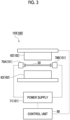
- Fig. 1 is a block diagram showing a configuration of a forming system 100 according to the present embodiment.
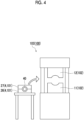
- Figs. 2 to 4 are schematic configuration diagrams showing specific examples of the forming system 100 shown in Fig. 1 .
- the forming system 100 is a system for manufacturing a formed product by heating a plated metal material and forming the heated metal material with a forming die.
- a pipe-shaped metal pipe material 40 as shown in Fig. 2 or a plate-shaped metal material 50 as shown in Fig. 3 is adopted.
- the metal material for example, a carbon steel material, an MnB steel material having improved hardenability, or the like is adopted.
- a plated metal material is adopted.
- the plated metal material is a material in which a surface of a steel material is covered with a plating. Details of the plating will be described later.
- the forming system 100 includes a heating unit 101, a forming device 103 having a forming die 102, and a plating deviation suppression mechanism 104.
- the heating unit 101 causes a current to flow through the plated metal material to heat the metal material.
- the heating unit 101 includes an electrode for causing the current to flow through the metal material by coming into contact with the metal material, and a power supply for causing the current to flow through the electrode. Accordingly, due to an electric resistance of the metal material itself, the metal material itself generates heat by Joule heat (energization heating).
- the forming device 103 is a device that forms the metal material heated by the heating unit 101 with the forming die 102.
- the forming device 103 a configuration shown in Fig. 2 may be adopted.
- the forming device 103 shown in Fig. 2 is a device that performs forming and quenching by supplying a fluid to the heated metal pipe material 40 and bringing the fluid into contact with a forming surface of the forming die.
- the forming device 103 includes the heating unit 101.
- the forming device 103 is a device that forms a metal pipe having a hollow shape by blow forming.
- the forming device 103 is installed on a horizontal plane.
- the forming device 103 includes the forming die 102, a drive mechanism 3, a holding unit 4, the heating unit 101, a fluid supply unit 6, a cooling unit 7, and a control unit 8.
- the metal pipe material 40 (metal material) refers to a hollow article before completion of the forming by the forming device 103.
- the metal pipe material 40 is a steel-type pipe material that can be hardened.
- a direction in which the metal pipe material 40 extends during forming may be referred to as a "longitudinal direction”
- a direction perpendicular to the longitudinal direction may be referred to as a "width direction”.
- the forming die 102 is a die that forms a metal pipe from the metal pipe material 40, and includes a lower die 11 and an upper die 12 that face each other in a vertical direction.
- the lower die 11 and the upper die 12 are made of steel blocks.
- Each of the lower die 11 and the upper die 12 is provided with a recessed portion in which the metal pipe material 40 is accommodated. With the lower die 11 and the upper die 12 in close contact with each other (die closed state), respective recessed portions thereof form a space having a target shape in which the metal pipe material is to be formed. Therefore, a surface of each of the recessed portions serves as the forming surface of the forming die 102.
- the lower die 11 is fixed to a base stage 13 via a die holder or the like.
- the upper die 12 is fixed to a slide of the drive mechanism 3 via a die holder or the like.
- the drive mechanism 3 is a mechanism that moves at least one of the lower die 11 and the upper die 12.
- the drive mechanism 3 has a configuration in which only the upper die 12 is moved.
- the drive mechanism 3 includes a slide 21 that moves the upper die 12 such that the lower die 11 and the upper die 12 are joined together, and a pull-back cylinder 22 serving as an actuator that generates a force for pulling the slide 21 upward, a main cylinder 23 serving as a drive source that downward-pressurizes the slide 21, and a drive source 24 that applies a driving force to the main cylinder 23.
- the holding unit 4 is a mechanism that holds the metal pipe material 40 disposed between the lower die 11 and the upper die 12.
- the holding unit 4 includes a lower electrode 26 and an upper electrode 27 that hold the metal pipe material 40 on one end side in the longitudinal direction of the forming die 102, and a lower electrode 26 and an upper electrode 27 that holds the metal pipe material 40 on the other end side in the longitudinal direction of the forming die 102.
- the lower electrodes 26 and the upper electrodes 27 on both sides in the longitudinal direction hold the metal pipe material 40 by sandwiching vicinities of the end portions of the metal pipe material 40 from the vertical direction.
- groove portions having a shape corresponding to an outer peripheral surface of the metal pipe material 40 are formed on an upper surface of the lower electrode 26 and a lower surface of the upper electrode 27.
- the lower electrode 26 and the upper electrode 27 are provided with drive mechanisms (not shown) and are movable independently in the vertical direction.
- the heating unit 101 heats the metal pipe material 40.
- the heating unit 101 is a mechanism that heats the metal pipe material 40 by energizing the metal pipe material 40.
- the heating unit 101 heats the metal pipe material 40 in a state in which the metal pipe material 40 is spaced apart from the lower die 11 and the upper die 12 between the lower die 11 and the upper die 12.
- the heating unit 101 includes the lower electrodes 26 and the upper electrodes 27 on both sides in the longitudinal direction as described above, and a power supply 28 that causes a current to flow through the metal pipe material 40 via the electrodes 26 and 27.
- a state in which the metal pipe material 40 is disposed inside the forming die 102 is a state in which the metal pipe material 40 is disposed in a space between the upper die 12 and the lower die 11 with respect to the upper die 12 and the lower die 11 facing each other.
- the metal pipe material 40 faces the upper die 12 in a state of being spaced downward with respect to the upper die 12, and faces the lower die 11 in a state of being spaced upward with respect to the lower die 11.
- the fluid supply unit 6 is a mechanism that supplies a high-pressure fluid into the metal pipe material 40 held between the lower die 11 and the upper die 12.
- the fluid supply unit 6 supplies a high-pressure fluid to the metal pipe material 40 which has become a high-temperature state by being heated by the heating unit 101 and expands the metal pipe material 40.
- the fluid supply units 6 are provided on both end sides of the forming die 102 in the longitudinal direction.
- the fluid supply unit 6 includes a nozzle 31 that supplies a fluid from an opening portion of an end portion of the metal pipe material 40 to the inside of the metal pipe material 40, a drive mechanism 32 that moves the nozzle 31 forward and backward with respect to the opening portion of the metal pipe material 40, and a supply source 33 that supplies the high-pressure fluid into the metal pipe material 40 via the nozzle 31.
- the drive mechanism 32 causes the nozzle 31 to be brought into close contact with the end portion of the metal pipe material 40 in a state in which sealing performance is secured during fluid supply and exhaust, and causes the nozzle 31 to be spaced apart from the end portion of the metal pipe material 40 at other times.
- the fluid supply unit 6 may supply a gas such as high-pressure air or inert gas as the fluid.
- the fluid supply unit 6 may include the heating unit 101 together with the holding unit 4 having a mechanism that moves the metal pipe material 40 in the vertical direction as the same device.
- the cooling unit 7 is a mechanism that cools the forming die 102. By cooling the forming die 102, the cooling unit 7 can rapidly cool the metal pipe material 40 when the expanded metal pipe material 40 has come into contact with the forming surface of the forming die 102.
- the cooling unit 7 includes a flow path 36 formed inside the lower die 11 and the upper die 12, and a water circulation mechanism 37 that supplies cooling water to the flow path 36 and circulates the cooling water.
- the control unit 8 is a device that controls the entire forming device 103.
- the control unit 8 controls the drive mechanism 3, the holding unit 4, the heating unit 101, the fluid supply unit 6, and the cooling unit 7.
- the control unit 8 repeatedly performs an operation of forming the metal pipe material 40 with the forming die 102.
- the control unit 8 controls the drive mechanism 3 to lower the upper die 12 and bring the upper die 12 close to the lower die 11 to close the forming die 102.
- the control unit 8 controls the fluid supply unit 6 to seal the opening portions of both ends of the metal pipe material 40 with the nozzle 31 and supply the fluid. Accordingly, the metal pipe material 40 softened by heating expands and comes into contact with the forming surface of the forming die 102. Then, the metal pipe material 40 is formed so as to follow a shape of the forming surface of the forming die 102.
- a part of the metal pipe material 40 is made to enter a gap between the lower die 11 and the upper die 12, and then the die is further closed to crush the entering portion to form a flange portion.
- quenching of the metal pipe material 40 is performed by being rapidly cooled with the forming die 102 cooled by the cooling unit 7.
- the forming device 103 As the forming device 103, a configuration shown in Fig. 3 may be adopted.
- the forming device 103 shown in Fig. 3 is a device that performs forming and quenching by bringing the heated flat plate-shaped metal material 50 into contact with the forming surface of the forming die 102.
- the forming device 103 includes the heating unit 101.
- the forming device 103 includes the forming die 102 that forms a formed product by forming the metal material 50.
- the forming die 102 includes an upper die 62 that comes into contact with an upper surface of the metal material 50 and a lower die 63 that comes into contact with a lower surface of the metal material 50.
- the forming surface (lower surface) of the upper die 62 and the forming surface (upper surface) of the lower die 63 may be formed in a shape corresponding to, for example, a hat shape or the like.
- the forming device 103 includes a drive unit (not shown) that moves at least one of the upper die 62 and the lower die 63.
- the forming device 103 forms the metal material 50 into the shape of the formed product by sandwiching the metal material 50 between the forming surface of the upper die 62 and the forming surface of the lower die 63.
- the configuration of the forming die 102 is not limited to a configuration in which dies are disposed so as to face each other in the vertical direction as the upper die 62 and the lower die 63, and the dies may be disposed so as to face each other in a horizontal direction.
- the number of dies constituting the forming die 102 is not limited to two, and the dies may be divided into three or more.
- the heating unit 101 heats the metal material 50 disposed inside the forming die 102.
- a state in which the metal material 50 is disposed inside the forming die 102 has the same meaning as in Fig. 2 , and is a state in which the metal material 50 is disposed in a space between the upper die 62 and the lower die 63 with respect to the upper die 62 and the lower die 63 facing each other.
- the heating unit 101 causes a current to flow through the metal material 50 to heat the metal material 50.
- the heating unit 101 includes a pair of electrodes 70A and 70B and a power supply 71.
- the electrodes 70A and 70B are members that come into contact with the metal material 50 and cause a current to flow through the metal material 50. Accordingly, due to an electric resistance of the metal material 50 itself, the metal material 50 itself generates heat by Joule heat (energization heating).
- the power supply 71 is connected to the electrodes 70A and 70B and causes a current to flow through the metal material 50 via the electrodes 70A and 70B.
- the electrodes 70A and 70B are in contact with the end portions of the metal material 50 in the longitudinal direction, respectively.
- the arrangement in which the electrodes 70A and 70B are in contact with the metal material 50 is not particularly limited.
- the electrodes 70A and 70B may have a function of holding the metal material 50, a holding mechanism other than the electrodes 70A and 70B may be separately provided.
- the configuration in which the electrodes 70A and 70B are provided with respect to the forming device 103 is not particularly limited.
- the electrodes 70A and 70B may be attached to the forming die 102.
- the electrodes 70A and 70B may be removed from the forming die 102 at a timing when the energization heating is completed and the upper die 62 and the lower die 63 are closed.
- the electrodes 70A and 70B may be provided at positions separated from the forming die 102 so that the upper die 62 and the lower die 63 do not interfere with the electrodes 70A and 70B even when the upper die 62 and the lower die 63 are closed.
- the electrodes 70A and 70B may be provided with an actuator (not shown) such that the electrodes 70A and 70B are movable with respect to the forming die 102.
- the forming system 100 includes a control unit 80.
- the control unit 80 is a device that controls the entire forming system 100.
- the control unit 80 is electrically connected to the power supply 71 of the heating unit 101.
- the control unit 80 controls a heating timing by the heating unit 101 by transmitting a control signal to the power supply 71 and controls a heating temperature by adjusting a magnitude of the current.
- the heating unit 101 and the forming device 103 are provided as separate devices.
- the heating unit 101 can heat the metal pipe material 40 outside the forming die 102.
- the heating unit 101 heats the metal pipe material 40 to an A3 point or higher, that is, 800°C or higher.
- a state in which the heating unit 101 performs heating outside the forming die 102 is a state in which heating is performed outside a space facing the dies 12 and 11.
- the heating unit 101 is provided at a position different from that of the forming device 103.
- the metal pipe material 40 heated by the heating unit 101 is set in the forming device 103 by a transport device such as a robot hand (not shown).
- Other configurations of the forming device 103 are the same as those of the forming device 103 shown in Fig. 2 .
- the forming system 100 that forms the flat plate-shaped metal material 50 as shown in Fig. 3 may also have a configuration in which the heating unit 101 performs heating outside the forming die 102.
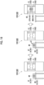
- the heating unit 101 may perform two-step heating as shown in Fig. 18 .
- the heating unit 101 performs heating outside the forming die 102 (left figure of Fig. 18 ).
- the heating unit 101 heats the metal pipe material 40 to 500°C or higher and an A3 point or lower, that is, 800°C or lower.
- the metal pipe material 40 is transported together with the heating unit 101 into the forming die 102 by the transport device (center figure of Fig. 18 ).
- the heating unit 101 heats the metal pipe material 40 in the forming die 102 (right figure of Fig. 18 ). In this case, the heating unit 101 heats the metal pipe material 40 to an A3 point or higher, that is, 800°C or higher.
- the first external heating of the forming die 102 may be performed by a furnace or the like. As a result, it is possible to suppress a decrease in degree of freedom of forming due to an increase in deformation resistance of the pipe, which is caused by a decrease in pipe temperature at the start of forming due to a decrease in temperature of the pipe being transported. In addition, when the metal pipe material 40 is heated by the forming die 102, since the heating is already performed externally, it is possible to form the pipe while suppressing the deviation.
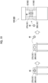
- the heating unit 101 shown in Fig. 19 performs two-step heating and performs natural air cooling after first heating.
- the heating unit 101 performs heating outside the forming die 102 (left figure of Fig. 19 ).
- the heating unit 101 heats the metal pipe material 40 to 500°C or higher and an A3 point or lower, that is, 800°C or lower.
- the metal pipe material 40 is removed from the heating unit 101, and natural air cooling is performed (center figure of Fig. 19 ).
- the metal pipe material 40 is disposed in the heating unit 101 provided in the forming die 102, and the heating unit 101 heats the metal pipe material 40 in the forming die 102 (right figure of Fig. 19 ).
- the heating unit 101 heats the metal pipe material 40 to an A3 point or higher, that is, 800°C or higher.
- the first external heating of the forming die 102 may be performed by a furnace or the like. Accordingly, it is possible to suppress a deformation resistance of the pipe caused by a decrease in temperature of the pipe due to natural heat radiation.
- the metal pipe material 40 is heated by the forming die 102, since the heating is already performed externally, it is possible to form the pipe while suppressing the deviation.
- the plating deviation suppression mechanism 104 is a mechanism that suppresses the deviation of the plating in the metal material due to energization heating.
- the deviation of the plating of the metal material will be described.
- the metal material can be quenched at the same time as the forming.
- the surface of the metal material is plated with a plating material.
- the plating material include an AlSi plating material.
- a melting point of aluminum is 652°C which is lower than 900 to 1000°C which is a temperature equal to or higher than an Ac3 point which is a heating target temperature at the time of quenching. Therefore, there is a possibility that the plating on the surface of the metal material may be melted during energization heating.
- an aluminum plating reacts with the iron of the base material, and an alloying reaction between the iron and aluminum proceeds to form, for example, an intermetallic compound (FeAl 3 ) having a melting point and a boiling point of 1000°C or higher.
- an alloying reaction proceeds before reaching the melting point of 652°C of the aluminum, and the melting of the aluminum is avoided.
- the plating deviation suppression mechanism 104 suppresses the occurrence of such a deviation of the plating and secures the uniformity of the plating thickness of the metal material.
- Fig. 5A is a schematic cross-sectional view showing a state in which a plating 52 is uniformly formed on a surface of a base material 51 in the flat plate-shaped metal material 50.
- Fig. 5B is a schematic cross-sectional view showing a state in which the plating 52 on the surface of the base material 51 has deviated to a predetermined location in the flat plate-shaped metal material 50.
- Fig. 5C is a schematic cross-sectional view showing a state in which a plating 42 is uniformly formed on a surface of a base material 41 in the pipe-shaped metal pipe material 40.
- Fig. 5A is a schematic cross-sectional view showing a state in which a plating 52 is uniformly formed on a surface of a base material 51 in the flat plate-shaped metal material 50.
- Fig. 5B is a schematic cross-sectional view showing a state in which the plating 52 on the surface of the base material 51 has deviated to a predetermined location in the flat plate-
- 5D is a schematic cross-sectional view showing a state in which the plating 42 on the surface of the base material 41 has deviated to a predetermined location in the pipe-shaped metal pipe material 40.
- the plating deviation suppression mechanism 104 is not provided in the forming system, the deviation of the plating occurs as shown in Figs. 5B and 5D .
- the plating deviation suppression mechanism 104 can suppress the deviation of the plating to form a layer of the plating 52 having a uniform thickness, as shown in Figs. 5A and 5C .
- Fig. 6A shows a distribution of a magnetic field generated around the metal material 50 during energization heating in a case where the plate-shaped metal material 50 is energized and heated.
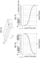
- Fig. 7A when a current flows in one direction of the metal material 50, a magnetic field is generated in the metal material 50, and the distribution thereof is as shown in Fig. 7B .
- a direction and a magnitude of the magnetic field generated in the metal material 50 are schematically shown on the upper side of Fig. 7B , and a graph of the magnetic field of the metal material 50 is shown on the lower side of Fig. 7B .
- a current flows while generating such a magnetic field distribution.
- a Lorentz force according to the Fleming's left-hand rule acts.
- the direction and the magnitude of the magnetic field generated in the metal material 50 are schematically shown on the upper side of Fig. 7C , and a graph of the Lorentz force of the metal material 50 is shown on the lower side of Fig. 7C .
- a direction of the Lorentz force is a negative side in an X direction of the metal material 50 on a positive side in the X direction and is the positive side in the X direction of the metal material 50 on the negative side in the X direction (see Fig. 7C ). Therefore, if the plating melts during energization heating, the melted plating deviates to the center in the X direction.
- the plating deviation suppression mechanism 104 may electrically suppress the deviation of the plating.
- To electrically suppress the deviation of the plating is to suppress the deviation of the plating by controlling a way to flow a current flowing through the metal material 50 by the heating unit 101.
- the plating deviation suppression mechanism 104 may suppress the current for energization heating.
- such electrical suppression of the deviation of the plating may be applied to any type of the forming system 100 of Figs. 2 to 4 .
- the plating deviation suppression mechanism 104 is composed of the heating unit 101 and the control unit 8 and 80 for controlling the heating unit 101.
- FIG. 9 shows a graph CG1 of a current when the plating deviation suppression mechanism 104 performs a current control for suppressing the deviation of the plating, and a graph TG1 of a temperature transition when the current control is performed.
- a graph CG2 and a graph TG2 are graphs when the current control for suppressing the deviation of the plating is not performed.
- the plating deviation suppression mechanism 104 causes a current to flow in a state of being suppressed to a current lower than that of the graph CG2 according to a comparative example. In this way, when the plating deviation suppression mechanism 104 suppresses the current by performing the current control, the magnetic field shown in Fig.
- a heating time is lengthened by an amount of suppression of the current.
- the plating deviation suppression mechanism 104 is not particularly limited, but may suppress a current related to energization heating to a range of 4 kA to 10 kA. When the current is larger than the above range, the suppression effect is low, and when the current is smaller than the above range, energization heating takes too long. In addition, when the current is not suppressed, the current for energization heating is in a range of 9 kA to 18 kA.
- a dielectric current as shown in Fig. 8A is generated at the start of energization heating. Therefore, a repulsive force is generated in the metal material 50.
- a dielectric current as shown in Fig. 8B is generated at the end of energization heating. Therefore, an attractive force is generated in the metal material 50. Due to an influence of such a repulsive force or an attractive force, the deviation of the plating occurs.
- the plating deviation suppression mechanism 104 may suppress a change in the current when the energization heating is stopped, as a method of electrically suppressing the deviation of the plating.
- the plating deviation suppression mechanism 104 when the energization heating is stopped, the plating deviation suppression mechanism 104 does not abruptly stop the current (refer to an imaginary line) as shown at a location "A" in Fig. 9 , but gradually decreases the current to reduce the current so as to draw a curve. In this way, by suppressing the change in the current when the energization heating is stopped, it is possible to suppress the attractive force shown in Fig. 8B and suppress the deviation of the plating.
- the plating deviation suppression mechanism 104 may change the current in a range of, for example, about half of an initial current value from the initial current value.
- Fig. 6B shows a magnetic field distribution when the metal pipe material 40 is energized and heated. Since the shape of the metal pipe material 40 is point-symmetrical, a surrounding magnetic field is also symmetrically distributed. As a result, the magnetic field in a direction perpendicular to the surface of the material becomes zero (refer to Fig. 10B ). Therefore, the attractive force in a tangential direction also becomes zero (refer to Fig. 10C ) and the deviation of the melted plating is suppressed. On the other hand, as shown in Fig.
- the plating deviation suppression mechanism 104 may mechanically suppress the deviation of the plating. Mechanically suppressing the deviation of the plating means suppressing the plating by structural adjustment.
- the plating deviation suppression mechanism 104 separates the metal pipe material 40 and the magnetic body (forming die 102) from each other by a predetermined distance or more during energization heating.
- the plating deviation suppression mechanism 104 is configured by the heating unit 101 that positions the metal pipe material 40 during energization heating.
- the plating deviation suppression mechanism 104 is configured by the heating unit 101 that heats the metal material outside the forming die 102.
- the plating deviation suppression mechanism 104 is configured by the heating unit 101 disposed externally (refer to Fig. 4 ).
- the plating deviation suppression mechanism 104 may be configured by a magnetic shield disposed around the metal material during energization heating.
- such a machine plating deviation suppression mechanism 104 may be applied to the forming system 100 for the flat plate-shaped metal material 50.
- the distance may be 20 mm or more.
- the distance when the distance is 20 mm, the Lorentz force in the tangential direction becomes large, but when the distance is greater than 20 mm, the Lorentz force can be suppressed.
- 12A to 12C shows results of analyzing the Lorentz force acting per unit area in four cases where distances from the surface of the pipe to the die are 20 mm, 50 mm, and 100 mm and the die is not present, assuming that an outer diameter of the metal pipe material 40 is 60 mm, a plate thickness is 1 mm, a pipe length is 1000 mm, and an energization current is 9000 A.
- a magnetic shield 105 constituting the plating deviation suppression mechanism 104 is configured to cover a periphery of the metal pipe material 40 during energization heating.
- the magnetic shield 105 is composed of two semi-circular members and covers the metal pipe material 40 by combining the two members during energization heating. Further, at the time of forming, the magnetic shield 105 is retracted from the periphery of the metal pipe material 40.
- the heating rate was controlled to be 15°C/sec and 150°C/sec (first, a current value for a target heating rate was confirmed, and an experiment was performed with a fixed current value).
- die positions in a case of internal heating the upper die was retracted to a position where there is no influence of the magnetic field, and lifting positions (lower die lifting positions) by the heating unit 101 were set to two positions of 45 mm and 70 mm for the lower die to perform measurements.
- the lifting position is 45 mm, a distance between the metal pipe material 40 and the die is 15 mm, and when the lifting position is 70 mm, the distance is 40 mm.
- Fig. 13 shows observation results of appearance under various conditions.
- the lower die lifting position is 45 mm and the heating rate is 150°C/sec
- portions where the plating is thick are confirmed at positions on both sides adjacent to a bead position. That is, it is confirmed that the deviation of the plating occurs.
- the thickness of the plating is even under other conditions and the deviation of the plating is suppressed.
- external heating it is possible to particularly reduce the deviation of the plating. Accordingly, it can be confirmed that the deviation of the plating can be suppressed by increasing the distance of the die or performing heating externally.
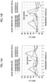
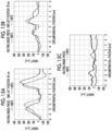
- Figs. 14A to 16B are graphs showing a distribution of a height of the surface of the metal pipe material 40 in a circumferential direction under various conditions. From Figs. 14A and 14B , it is possible to confirm a correlation between the distance between the metal pipe material 40 and the die and the deviation of the plating. In any of Figs. 14A and 14B , the larger the distance, the more the deviation of the plating can be suppressed. From this, it can be confirmed that as the distance between the metal pipe material 40 and the surrounding magnetic body (die or the like) increases, the deviation of the plating can be reduced.
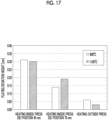
- Fig. 17 is a bar graph showing the maximum height of the deviation of the plating under each condition. From the above graph, it is confirmed that the effect of suppressing the deviation of the plating becomes large by increasing the distance between the metal pipe material 40 and the die.
- the forming system 100 includes the heating unit 101 that causes the current to flow through the plated metal material to heat the metal material, the forming die 102 that forms the heated metal material, and the plating deviation suppression mechanism 104 that suppresses the deviation of the plating in the metal material due to energization heating.
- the heating unit 101 causes the current to flow through the plated metal material to heat the metal material. Therefore, the plating may be melted by the heat of energization heating.
- the forming system 100 includes a plating deviation suppression mechanism 104 that suppresses the deviation of the plating in the metal material due to energization heating. Therefore, it is possible to suppress the deviation of the plating which is melted due to energization heating. As described above, it is possible to suppress the deviation of the plating of the metal material.
- the plating deviation suppression mechanism 104 may electrically suppress the deviation of the plating. In this case, the plating deviation suppression mechanism 104 can easily suppress the deviation of the plating by electrical adjustment during energization heating.
- the plating deviation suppression mechanism 104 may suppress a change in the current when energization heating is stopped. In this case, in a case where a magnetic body exists around the metal material, it is possible to suppress a magnitude of a force generated between the metal material and the magnetic body due to a sudden change in the current.
- the plating deviation suppression mechanism 104 may suppress the current for energization heating. In this case, in a case where the magnetic body exists around the metal material, it is possible to suppress the magnitude of the force generated between the metal material and the magnetic body during energization heating.
- the plating deviation suppression mechanism 104 may mechanically suppress the deviation of the plating. In this case, a force generated during energization heating in relation to the magnetic body existing around the metal material can be suppressed by structural consideration.
- the plating deviation suppression mechanism 104 may separate the metal material and the magnetic body from each other by a predetermined distance or more during energization heating. In this case, it is possible to suppress a force generated between the magnetic body and the metal material during energization heating.
- the plating deviation suppression mechanism 104 may be configured by the heating unit 101 that heats the metal material outside the forming die. In this case, it is possible to suppress an influence of a force generated between the forming die and the metal material during energization heating.
- the plating deviation suppression mechanism 104 may be configured by the magnetic shield 105 disposed around the metal material during energization heating. In this case, it is possible to suppress the generation of the force between the forming die and the metal material during energization heating.
- the present invention is not limited to the above-described embodiments.
- the forming devices of Figs. 2 to 4 are merely examples, and the forming device may have any configuration without departing from the concept of the present invention.
Landscapes
- Engineering & Computer Science (AREA)
- Mechanical Engineering (AREA)
- Physics & Mathematics (AREA)
- Fluid Mechanics (AREA)
- Thermal Sciences (AREA)
- Shaping Metal By Deep-Drawing, Or The Like (AREA)
- Moulds For Moulding Plastics Or The Like (AREA)
- Heating, Cooling, Or Curing Plastics Or The Like In General (AREA)
- Coating With Molten Metal (AREA)
Abstract
Description
- The present invention relates to a forming system.
- In the related art, a forming system described in
PTL 1 is known. In this forming system, a metal material is heated and the heated metal pipe material is formed by a forming die, so that the metal pipe material is shaped into a shape of a forming surface of the forming die. In addition, the metal material is quenched at the same time as the forming. - [PTL 1]
Japanese Unexamined Patent Publication No. 2009-220141 - Here, in a case where forming is performed by bringing the heated metal material into contact with the forming die as described above, oxide scales may be generated on a surface of the metal material due to heating. Therefore, there is a case where the generation of the oxide scales is suppressed by plating the surface of the metal material. However, there is a case where a plating is melted when energization heating is performed, and a deviation of the plating occurs due to an influence of a magnetic field generated by an energization current.
- An aspect of the present invention has been made to solve such a problem, and an object of the present invention is to provide a forming system capable of reducing a deviation of a plating in a metal material.
- A forming system according to an aspect of the present invention includes a heating unit that causes a current to flow through a plated metal material to heat the metal material, a forming die that forms the heated metal material, and a plating deviation suppression mechanism that suppresses a deviation of a plating in the metal material due to energization heating.
- In the forming system, the heating unit causes a current to flow through the plated metal material to heat the metal material. Therefore, the plating may be melted by the heat of energization heating. On the other hand, the forming system is provided with the plating deviation suppression mechanism that suppresses the deviation of the plating in the metal material due to energization heating. Therefore, it is possible to suppress the deviation of the plating which is melted due to energization heating. As described above, it is possible to suppress the deviation of the plating of the metal material.
- The plating deviation suppression mechanism may electrically suppress the deviation of the plating. In this case, the plating deviation suppression mechanism can easily suppress the deviation of the plating by electrical adjustment during energization heating.
- The plating deviation suppression mechanism may suppress a change in a current when energization heating is stopped. In this case, in a case where a magnetic body exists around the metal material, it is possible to suppress a magnitude of a force generated between the metal material and the magnetic body due to a sudden change in the current.
- The plating deviation suppression mechanism may suppress a current for energization heating. In this case, in a case where the magnetic body exists around the metal material, it is possible to suppress the magnitude of the force generated between the metal material and the magnetic body during energization heating.
- The plating deviation suppression mechanism may mechanically suppress the deviation of the plating. In this case, a force generated during energization heating in relation to the magnetic body existing around the metal material can be suppressed by structural consideration.
- The plating deviation suppression mechanism may separate the metal material and the magnetic body from each other by a predetermined distance or more during energization heating. In this case, it is possible to suppress a force generated between the magnetic body and the metal material during energization heating.
- The plating deviation suppression mechanism may be configured by the heating unit that heats the metal material outside the forming die. In this case, it is possible to suppress an influence of a force generated between the forming die and the metal material during energization heating.
- The plating deviation suppression mechanism may be configured by a magnetic shield disposed around the metal material during energization heating. In this case, it is possible to suppress the generation of the force between the forming die and the metal material during energization heating.
- According to one aspect of the present invention, it is possible to provide a forming system capable of reducing the deviation of the plating in the metal material.
-
-
Fig. 1 is a block diagram showing a configuration of a forming system according to an embodiment of the present invention. -
Fig. 2 is a schematic configuration diagram showing a specific example of the forming system shown inFig. 1 . -
Fig. 3 is a schematic configuration diagram showing a specific example of the forming system shown inFig. 1 . -
Fig. 4 is a schematic configuration diagram showing a specific example of the forming system shown inFig. 1 . -
Figs. 5A to 5D are schematic cross-sectional views showing a state of a deviation of a plating. -
Figs. 6A to 6C are diagrams showing a distribution of a magnetic field generated around a metal material during energization heating. -
Figs. 7A to 7C are diagrams for explaining a Lorentz force generated in a plate-shaped metal material. -
Figs. 8A and 8B are conceptual diagrams for explaining a force generated between a metal material and a magnetic body. -
Fig. 9 is a graph of a current and a graph of a transition of a temperature. -
Figs. 10A to 10C are diagrams for explaining a Lorentz force generated in a metal pipe material. -
Fig. 11 is a conceptual diagram showing a magnetic shield. -
Figs. 12A to 12C are diagrams showing analysis results indicating a relationship between a Lorentz force and a distance between a metal pipe material and a die. -
Fig. 13 is a diagram showing experimental results. -
Figs. 14A and 14B are diagrams showing experimental results. -
Figs. 15A to 15C are diagrams showing experimental results. -
Figs. 16A and 16B are diagrams showing experimental results. -
Fig. 17 is a diagram showing experimental results. -
Fig. 18 is a schematic configuration diagram showing a specific example of the forming system shown inFig. 1 . -
Fig. 19 is a schematic configuration diagram showing a specific example of the forming system shown inFig. 1 . - Hereinafter, a preferred embodiment of the present invention will be described with reference to the drawings. In addition, in the respective drawings, the same portions or corresponding portions are designated by the same reference signs, and duplicated descriptions will not be repeated.
-
Fig. 1 is a block diagram showing a configuration of a formingsystem 100 according to the present embodiment. In addition,Figs. 2 to 4 are schematic configuration diagrams showing specific examples of the formingsystem 100 shown inFig. 1 . - The forming
system 100 is a system for manufacturing a formed product by heating a plated metal material and forming the heated metal material with a forming die. As the metal material, a pipe-shapedmetal pipe material 40 as shown inFig. 2 or a plate-shapedmetal material 50 as shown inFig. 3 is adopted. As the metal material, for example, a carbon steel material, an MnB steel material having improved hardenability, or the like is adopted. In the present embodiment, a plated metal material is adopted. The plated metal material is a material in which a surface of a steel material is covered with a plating. Details of the plating will be described later. - As shown in
Fig. 1 , the formingsystem 100 includes aheating unit 101, a formingdevice 103 having a formingdie 102, and a platingdeviation suppression mechanism 104. - The
heating unit 101 causes a current to flow through the plated metal material to heat the metal material. Theheating unit 101 includes an electrode for causing the current to flow through the metal material by coming into contact with the metal material, and a power supply for causing the current to flow through the electrode. Accordingly, due to an electric resistance of the metal material itself, the metal material itself generates heat by Joule heat (energization heating). The formingdevice 103 is a device that forms the metal material heated by theheating unit 101 with the formingdie 102. - For example, as the forming
device 103, a configuration shown inFig. 2 may be adopted. The formingdevice 103 shown inFig. 2 is a device that performs forming and quenching by supplying a fluid to the heatedmetal pipe material 40 and bringing the fluid into contact with a forming surface of the forming die. The formingdevice 103 includes theheating unit 101. - As shown in
Fig. 2 , the formingdevice 103 is a device that forms a metal pipe having a hollow shape by blow forming. Here, the formingdevice 103 is installed on a horizontal plane. The formingdevice 103 includes the formingdie 102, adrive mechanism 3, a holdingunit 4, theheating unit 101, afluid supply unit 6, acooling unit 7, and acontrol unit 8. In addition, in the present specification, the metal pipe material 40 (metal material) refers to a hollow article before completion of the forming by the formingdevice 103. Themetal pipe material 40 is a steel-type pipe material that can be hardened. Additionally, in the horizontal direction, a direction in which themetal pipe material 40 extends during forming may be referred to as a "longitudinal direction", and a direction perpendicular to the longitudinal direction may be referred to as a "width direction". - The forming
die 102 is a die that forms a metal pipe from themetal pipe material 40, and includes alower die 11 and anupper die 12 that face each other in a vertical direction. Thelower die 11 and theupper die 12 are made of steel blocks. Each of thelower die 11 and theupper die 12 is provided with a recessed portion in which themetal pipe material 40 is accommodated. With thelower die 11 and theupper die 12 in close contact with each other (die closed state), respective recessed portions thereof form a space having a target shape in which the metal pipe material is to be formed. Therefore, a surface of each of the recessed portions serves as the forming surface of the formingdie 102. Thelower die 11 is fixed to abase stage 13 via a die holder or the like. Theupper die 12 is fixed to a slide of thedrive mechanism 3 via a die holder or the like. - The
drive mechanism 3 is a mechanism that moves at least one of thelower die 11 and theupper die 12. InFig. 2 , thedrive mechanism 3 has a configuration in which only theupper die 12 is moved. Thedrive mechanism 3 includes aslide 21 that moves theupper die 12 such that thelower die 11 and theupper die 12 are joined together, and a pull-back cylinder 22 serving as an actuator that generates a force for pulling theslide 21 upward, amain cylinder 23 serving as a drive source that downward-pressurizes theslide 21, and adrive source 24 that applies a driving force to themain cylinder 23. - The holding
unit 4 is a mechanism that holds themetal pipe material 40 disposed between thelower die 11 and theupper die 12. The holdingunit 4 includes alower electrode 26 and anupper electrode 27 that hold themetal pipe material 40 on one end side in the longitudinal direction of the formingdie 102, and alower electrode 26 and anupper electrode 27 that holds themetal pipe material 40 on the other end side in the longitudinal direction of the formingdie 102. Thelower electrodes 26 and theupper electrodes 27 on both sides in the longitudinal direction hold themetal pipe material 40 by sandwiching vicinities of the end portions of themetal pipe material 40 from the vertical direction. In addition, groove portions having a shape corresponding to an outer peripheral surface of themetal pipe material 40 are formed on an upper surface of thelower electrode 26 and a lower surface of theupper electrode 27. Thelower electrode 26 and theupper electrode 27 are provided with drive mechanisms (not shown) and are movable independently in the vertical direction. - The
heating unit 101 heats themetal pipe material 40. Theheating unit 101 is a mechanism that heats themetal pipe material 40 by energizing themetal pipe material 40. Theheating unit 101 heats themetal pipe material 40 in a state in which themetal pipe material 40 is spaced apart from thelower die 11 and theupper die 12 between thelower die 11 and theupper die 12. Theheating unit 101 includes thelower electrodes 26 and theupper electrodes 27 on both sides in the longitudinal direction as described above, and apower supply 28 that causes a current to flow through themetal pipe material 40 via theelectrodes - Here, a state in which the
metal pipe material 40 is disposed inside the formingdie 102 is a state in which themetal pipe material 40 is disposed in a space between theupper die 12 and thelower die 11 with respect to theupper die 12 and thelower die 11 facing each other. In this state, themetal pipe material 40 faces theupper die 12 in a state of being spaced downward with respect to theupper die 12, and faces thelower die 11 in a state of being spaced upward with respect to thelower die 11. - The
fluid supply unit 6 is a mechanism that supplies a high-pressure fluid into themetal pipe material 40 held between thelower die 11 and theupper die 12. Thefluid supply unit 6 supplies a high-pressure fluid to themetal pipe material 40 which has become a high-temperature state by being heated by theheating unit 101 and expands themetal pipe material 40. Thefluid supply units 6 are provided on both end sides of the formingdie 102 in the longitudinal direction. Thefluid supply unit 6 includes anozzle 31 that supplies a fluid from an opening portion of an end portion of themetal pipe material 40 to the inside of themetal pipe material 40, adrive mechanism 32 that moves thenozzle 31 forward and backward with respect to the opening portion of themetal pipe material 40, and asupply source 33 that supplies the high-pressure fluid into themetal pipe material 40 via thenozzle 31. Thedrive mechanism 32 causes thenozzle 31 to be brought into close contact with the end portion of themetal pipe material 40 in a state in which sealing performance is secured during fluid supply and exhaust, and causes thenozzle 31 to be spaced apart from the end portion of themetal pipe material 40 at other times. In addition, thefluid supply unit 6 may supply a gas such as high-pressure air or inert gas as the fluid. Additionally, thefluid supply unit 6 may include theheating unit 101 together with the holdingunit 4 having a mechanism that moves themetal pipe material 40 in the vertical direction as the same device. - The
cooling unit 7 is a mechanism that cools the formingdie 102. By cooling the formingdie 102, thecooling unit 7 can rapidly cool themetal pipe material 40 when the expandedmetal pipe material 40 has come into contact with the forming surface of the formingdie 102. Thecooling unit 7 includes aflow path 36 formed inside thelower die 11 and theupper die 12, and awater circulation mechanism 37 that supplies cooling water to theflow path 36 and circulates the cooling water. - The
control unit 8 is a device that controls the entire formingdevice 103. Thecontrol unit 8 controls thedrive mechanism 3, the holdingunit 4, theheating unit 101, thefluid supply unit 6, and thecooling unit 7. Thecontrol unit 8 repeatedly performs an operation of forming themetal pipe material 40 with the formingdie 102. - The
control unit 8 controls thedrive mechanism 3 to lower theupper die 12 and bring theupper die 12 close to thelower die 11 to close the formingdie 102. On the other hand, thecontrol unit 8 controls thefluid supply unit 6 to seal the opening portions of both ends of themetal pipe material 40 with thenozzle 31 and supply the fluid. Accordingly, themetal pipe material 40 softened by heating expands and comes into contact with the forming surface of the formingdie 102. Then, themetal pipe material 40 is formed so as to follow a shape of the forming surface of the formingdie 102. In addition, in a case where a metal pipe with a flange is formed, a part of themetal pipe material 40 is made to enter a gap between thelower die 11 and theupper die 12, and then the die is further closed to crush the entering portion to form a flange portion. When themetal pipe material 40 comes into contact with the forming surface, quenching of themetal pipe material 40 is performed by being rapidly cooled with the forming die 102 cooled by thecooling unit 7. - In addition, as the forming
device 103, a configuration shown inFig. 3 may be adopted. The formingdevice 103 shown inFig. 3 is a device that performs forming and quenching by bringing the heated flat plate-shapedmetal material 50 into contact with the forming surface of the formingdie 102. The formingdevice 103 includes theheating unit 101. - The forming
device 103 includes the forming die 102 that forms a formed product by forming themetal material 50. The formingdie 102 includes anupper die 62 that comes into contact with an upper surface of themetal material 50 and alower die 63 that comes into contact with a lower surface of themetal material 50. The forming surface (lower surface) of theupper die 62 and the forming surface (upper surface) of thelower die 63 may be formed in a shape corresponding to, for example, a hat shape or the like. The formingdevice 103 includes a drive unit (not shown) that moves at least one of theupper die 62 and thelower die 63. The formingdevice 103 forms themetal material 50 into the shape of the formed product by sandwiching themetal material 50 between the forming surface of theupper die 62 and the forming surface of thelower die 63. In addition, the configuration of the formingdie 102 is not limited to a configuration in which dies are disposed so as to face each other in the vertical direction as theupper die 62 and thelower die 63, and the dies may be disposed so as to face each other in a horizontal direction. In addition, the number of dies constituting the formingdie 102 is not limited to two, and the dies may be divided into three or more. - The
heating unit 101 heats themetal material 50 disposed inside the formingdie 102. Here, a state in which themetal material 50 is disposed inside the formingdie 102 has the same meaning as inFig. 2 , and is a state in which themetal material 50 is disposed in a space between theupper die 62 and thelower die 63 with respect to theupper die 62 and thelower die 63 facing each other. - The
heating unit 101 causes a current to flow through themetal material 50 to heat themetal material 50. Specifically, theheating unit 101 includes a pair ofelectrodes power supply 71. Theelectrodes metal material 50 and cause a current to flow through themetal material 50. Accordingly, due to an electric resistance of themetal material 50 itself, themetal material 50 itself generates heat by Joule heat (energization heating). Thepower supply 71 is connected to theelectrodes metal material 50 via theelectrodes - In the example shown in
Fig. 3 , theelectrodes metal material 50 in the longitudinal direction, respectively. The arrangement in which theelectrodes metal material 50 is not particularly limited. In addition, although theelectrodes metal material 50, a holding mechanism other than theelectrodes electrodes device 103 is not particularly limited. For example, theelectrodes die 102. In this case, theelectrodes upper die 62 and thelower die 63 are closed. Alternatively, theelectrodes upper die 62 and thelower die 63 do not interfere with theelectrodes upper die 62 and thelower die 63 are closed. Further, theelectrodes electrodes die 102. - As shown in
Fig. 2 , the formingsystem 100 includes acontrol unit 80. Thecontrol unit 80 is a device that controls the entire formingsystem 100. Thecontrol unit 80 is electrically connected to thepower supply 71 of theheating unit 101. Thecontrol unit 80 controls a heating timing by theheating unit 101 by transmitting a control signal to thepower supply 71 and controls a heating temperature by adjusting a magnitude of the current. - In addition, as the forming
system 100, a configuration shown inFig. 4 may be adopted. In the formingsystem 100 shown inFig. 4 , theheating unit 101 and the formingdevice 103 are provided as separate devices. Thus, theheating unit 101 can heat themetal pipe material 40 outside the formingdie 102. In this case, theheating unit 101 heats themetal pipe material 40 to an A3 point or higher, that is, 800°C or higher. A state in which theheating unit 101 performs heating outside the formingdie 102 is a state in which heating is performed outside a space facing the dies 12 and 11. In the example shown inFig. 4 , theheating unit 101 is provided at a position different from that of the formingdevice 103. Themetal pipe material 40 heated by theheating unit 101 is set in the formingdevice 103 by a transport device such as a robot hand (not shown). Other configurations of the formingdevice 103 are the same as those of the formingdevice 103 shown inFig. 2 . The formingsystem 100 that forms the flat plate-shapedmetal material 50 as shown inFig. 3 may also have a configuration in which theheating unit 101 performs heating outside the formingdie 102. - Alternatively, the
heating unit 101 may perform two-step heating as shown inFig. 18 . First, theheating unit 101 performs heating outside the forming die 102 (left figure ofFig. 18 ). At this time, theheating unit 101 heats themetal pipe material 40 to 500°C or higher and an A3 point or lower, that is, 800°C or lower. Next, themetal pipe material 40 is transported together with theheating unit 101 into the forming die 102 by the transport device (center figure ofFig. 18 ). Next, theheating unit 101 heats themetal pipe material 40 in the forming die 102 (right figure ofFig. 18 ). In this case, theheating unit 101 heats themetal pipe material 40 to an A3 point or higher, that is, 800°C or higher. The first external heating of the forming die 102 may be performed by a furnace or the like. As a result, it is possible to suppress a decrease in degree of freedom of forming due to an increase in deformation resistance of the pipe, which is caused by a decrease in pipe temperature at the start of forming due to a decrease in temperature of the pipe being transported. In addition, when themetal pipe material 40 is heated by the formingdie 102, since the heating is already performed externally, it is possible to form the pipe while suppressing the deviation. - In addition, a configuration shown in
Fig. 19 may be adopted. Theheating unit 101 shown inFig. 19 performs two-step heating and performs natural air cooling after first heating. First, theheating unit 101 performs heating outside the forming die 102 (left figure ofFig. 19 ). At this time, theheating unit 101 heats themetal pipe material 40 to 500°C or higher and an A3 point or lower, that is, 800°C or lower. Next, themetal pipe material 40 is removed from theheating unit 101, and natural air cooling is performed (center figure ofFig. 19 ). Next, themetal pipe material 40 is disposed in theheating unit 101 provided in the formingdie 102, and theheating unit 101 heats themetal pipe material 40 in the forming die 102 (right figure ofFig. 19 ). In this case, theheating unit 101 heats themetal pipe material 40 to an A3 point or higher, that is, 800°C or higher. The first external heating of the forming die 102 may be performed by a furnace or the like. Accordingly, it is possible to suppress a deformation resistance of the pipe caused by a decrease in temperature of the pipe due to natural heat radiation. In addition, when themetal pipe material 40 is heated by the formingdie 102, since the heating is already performed externally, it is possible to form the pipe while suppressing the deviation. - Returning to
Fig. 1 , the platingdeviation suppression mechanism 104 is a mechanism that suppresses the deviation of the plating in the metal material due to energization heating. Here, the deviation of the plating of the metal material will be described. In the devices shown inFigs. 2 to 4 , the metal material can be quenched at the same time as the forming. However, in order to perform sufficient quenching, it is necessary to heat the metal material to a temperature equal to or higher than an Ac3 point for austenite transformation at the time of energization heating. Therefore, when the metal material is heated to such a high temperature, there is a possibility that oxide scales are generated on the surface of the metal material. In order to suppress the generation of such oxide scales, the surface of the metal material is plated with a plating material. Examples of the plating material include an AlSi plating material. Here, in a case where AlSi is used as the plating material, a melting point of aluminum is 652°C which is lower than 900 to 1000°C which is a temperature equal to or higher than an Ac3 point which is a heating target temperature at the time of quenching. Therefore, there is a possibility that the plating on the surface of the metal material may be melted during energization heating. In such a melted plating, a strong attractive force acts in accordance with the Fleming's left-hand rule due to a magnetic field generated by a current and the current, and a phenomenon in which the melted plating moves (pinch effect), that is, a so-called deviation of the melted plating occurs. When a plating thickness of the metal material becomes non-uniform depending on locations, iron of a base material is exposed, which causes a problem in that the effect of suppressing the oxide scales is reduced. In a case of using the plated metal material, there is a problem in that the deviation of the melted plating occurs. For example, in a heating process, an aluminum plating reacts with the iron of the base material, and an alloying reaction between the iron and aluminum proceeds to form, for example, an intermetallic compound (FeAl3) having a melting point and a boiling point of 1000°C or higher. In a case where a heating rate is low, the alloying reaction proceeds before reaching the melting point of 652°C of the aluminum, and the melting of the aluminum is avoided. However, in a case where the heating rate is high and the melting point (652°C) of the aluminum is reached before sufficient alloying proceeds, a part of the aluminum plating is melted, and the above-described deviation occurs. Therefore, the platingdeviation suppression mechanism 104 suppresses the occurrence of such a deviation of the plating and secures the uniformity of the plating thickness of the metal material. - For example,
Fig. 5A is a schematic cross-sectional view showing a state in which aplating 52 is uniformly formed on a surface of abase material 51 in the flat plate-shapedmetal material 50.Fig. 5B is a schematic cross-sectional view showing a state in which theplating 52 on the surface of thebase material 51 has deviated to a predetermined location in the flat plate-shapedmetal material 50.Fig. 5C is a schematic cross-sectional view showing a state in which aplating 42 is uniformly formed on a surface of abase material 41 in the pipe-shapedmetal pipe material 40.Fig. 5D is a schematic cross-sectional view showing a state in which theplating 42 on the surface of thebase material 41 has deviated to a predetermined location in the pipe-shapedmetal pipe material 40. When the platingdeviation suppression mechanism 104 is not provided in the forming system, the deviation of the plating occurs as shown inFigs. 5B and 5D . On the other hand, the platingdeviation suppression mechanism 104 can suppress the deviation of the plating to form a layer of theplating 52 having a uniform thickness, as shown inFigs. 5A and 5C . -
Fig. 6A shows a distribution of a magnetic field generated around themetal material 50 during energization heating in a case where the plate-shapedmetal material 50 is energized and heated. In this case, as shown inFig. 7A , when a current flows in one direction of themetal material 50, a magnetic field is generated in themetal material 50, and the distribution thereof is as shown inFig. 7B . A direction and a magnitude of the magnetic field generated in themetal material 50 are schematically shown on the upper side ofFig. 7B , and a graph of the magnetic field of themetal material 50 is shown on the lower side ofFig. 7B . In themetal material 50 during energization heating, a current flows while generating such a magnetic field distribution. Therefore, a Lorentz force according to the Fleming's left-hand rule acts. The direction and the magnitude of the magnetic field generated in themetal material 50 are schematically shown on the upper side ofFig. 7C , and a graph of the Lorentz force of themetal material 50 is shown on the lower side ofFig. 7C . As shown inFig. 7C , a direction of the Lorentz force is a negative side in an X direction of themetal material 50 on a positive side in the X direction and is the positive side in the X direction of themetal material 50 on the negative side in the X direction (seeFig. 7C ). Therefore, if the plating melts during energization heating, the melted plating deviates to the center in the X direction. - On the other hand, the plating
deviation suppression mechanism 104 may electrically suppress the deviation of the plating. To electrically suppress the deviation of the plating is to suppress the deviation of the plating by controlling a way to flow a current flowing through themetal material 50 by theheating unit 101. Specifically, the platingdeviation suppression mechanism 104 may suppress the current for energization heating. In addition, such electrical suppression of the deviation of the plating may be applied to any type of the formingsystem 100 ofFigs. 2 to 4 . In a case where the platingdeviation suppression mechanism 104 electrically suppresses the deviation of the plating, the platingdeviation suppression mechanism 104 is composed of theheating unit 101 and thecontrol unit heating unit 101. For example,Fig. 9 shows a graph CG1 of a current when the platingdeviation suppression mechanism 104 performs a current control for suppressing the deviation of the plating, and a graph TG1 of a temperature transition when the current control is performed. In addition, a graph CG2 and a graph TG2 are graphs when the current control for suppressing the deviation of the plating is not performed. As shown in the graph CG1, the platingdeviation suppression mechanism 104 causes a current to flow in a state of being suppressed to a current lower than that of the graph CG2 according to a comparative example. In this way, when the platingdeviation suppression mechanism 104 suppresses the current by performing the current control, the magnetic field shown inFig. 7B becomes smaller, and as a result, the Lorentz force from the center shown inFig. 7C becomes smaller. Therefore, it is possible to suppress the deviation of the plating. In addition, in the graph CG1, a heating time is lengthened by an amount of suppression of the current. The platingdeviation suppression mechanism 104 is not particularly limited, but may suppress a current related to energization heating to a range of 4 kA to 10 kA. When the current is larger than the above range, the suppression effect is low, and when the current is smaller than the above range, energization heating takes too long. In addition, when the current is not suppressed, the current for energization heating is in a range of 9 kA to 18 kA. - Further, in a case where the forming
die 102, which is a magnetic body, exists near themetal material 50, a dielectric current as shown inFig. 8A is generated at the start of energization heating. Therefore, a repulsive force is generated in themetal material 50. On the other hand, a dielectric current as shown inFig. 8B is generated at the end of energization heating. Therefore, an attractive force is generated in themetal material 50. Due to an influence of such a repulsive force or an attractive force, the deviation of the plating occurs. On the other hand, the platingdeviation suppression mechanism 104 may suppress a change in the current when the energization heating is stopped, as a method of electrically suppressing the deviation of the plating. For example, when the energization heating is stopped, the platingdeviation suppression mechanism 104 does not abruptly stop the current (refer to an imaginary line) as shown at a location "A" inFig. 9 , but gradually decreases the current to reduce the current so as to draw a curve. In this way, by suppressing the change in the current when the energization heating is stopped, it is possible to suppress the attractive force shown inFig. 8B and suppress the deviation of the plating. Although not particularly limited, the platingdeviation suppression mechanism 104 may change the current in a range of, for example, about half of an initial current value from the initial current value. - Next, the deviation of the plating of the
metal pipe material 40 will be described.Fig. 6B shows a magnetic field distribution when themetal pipe material 40 is energized and heated. Since the shape of themetal pipe material 40 is point-symmetrical, a surrounding magnetic field is also symmetrically distributed. As a result, the magnetic field in a direction perpendicular to the surface of the material becomes zero (refer toFig. 10B ). Therefore, the attractive force in a tangential direction also becomes zero (refer toFig. 10C ) and the deviation of the melted plating is suppressed. On the other hand, as shown inFig. 6C , in a case where a magnetic body such as the formingdie 102 exists in the vicinity of themetal pipe material 40 at the time of energization heating, the uniformity of the magnetic field distribution collapses. As a result, the magnetic field in the direction perpendicular to the surface of the material is generated. Therefore, an attractive force in the tangential direction is generated in the metal pipe material 40 (refer toFigs. 12A to 12C ), and a phenomenon occurs in which the plating deviates. In response to such a phenomenon of the deviation of the plating, the platingdeviation suppression mechanism 104 may mechanically suppress the deviation of the plating. Mechanically suppressing the deviation of the plating means suppressing the plating by structural adjustment. In this case, the platingdeviation suppression mechanism 104 separates themetal pipe material 40 and the magnetic body (forming die 102) from each other by a predetermined distance or more during energization heating. In this case, the platingdeviation suppression mechanism 104 is configured by theheating unit 101 that positions themetal pipe material 40 during energization heating. Alternatively, the platingdeviation suppression mechanism 104 is configured by theheating unit 101 that heats the metal material outside the formingdie 102. In this case, the platingdeviation suppression mechanism 104 is configured by theheating unit 101 disposed externally (refer toFig. 4 ). The platingdeviation suppression mechanism 104 may be configured by a magnetic shield disposed around the metal material during energization heating. In addition, such a machine platingdeviation suppression mechanism 104 may be applied to the formingsystem 100 for the flat plate-shapedmetal material 50. - In a case where the plating
deviation suppression mechanism 104 separates themetal pipe material 40 and the magnetic body (forming die 102) from each other by a predetermined distance or more, the distance may be 20 mm or more. For example, as shown inFig. 12B , when the distance is 20 mm, the Lorentz force in the tangential direction becomes large, but when the distance is greater than 20 mm, the Lorentz force can be suppressed. The experiment shown inFigs. 12A to 12C shows results of analyzing the Lorentz force acting per unit area in four cases where distances from the surface of the pipe to the die are 20 mm, 50 mm, and 100 mm and the die is not present, assuming that an outer diameter of themetal pipe material 40 is 60 mm, a plate thickness is 1 mm, a pipe length is 1000 mm, and an energization current is 9000 A. - As shown in
Fig. 11 , amagnetic shield 105 constituting the platingdeviation suppression mechanism 104 is configured to cover a periphery of themetal pipe material 40 during energization heating. Themagnetic shield 105 is composed of two semi-circular members and covers themetal pipe material 40 by combining the two members during energization heating. Further, at the time of forming, themagnetic shield 105 is retracted from the periphery of themetal pipe material 40. - Next, with reference to
Figs. 13 to 17 , an experiment for evaluating the effect of suppressing the deviation of the plating by the platingdeviation suppression mechanism 104 will be described. In this experiment, an AlSi-plated thick (150 g/m2) t 1.2 mm material of "Usibor (registered trademark)" was used as themetal pipe material 40. In addition, measurements were performed for a case where energization heating is performed inside the formingdie 102 and for a case where energization heating is performed outside the formingdie 102. The heating temperatures were 900°C, 1000°C, 1100°C, and 1200°C in both cases of internal heating and external heating. As a condition for internal heating, the heating rate was controlled to be 15°C/sec and 150°C/sec (first, a current value for a target heating rate was confirmed, and an experiment was performed with a fixed current value). As die positions in a case of internal heating, the upper die was retracted to a position where there is no influence of the magnetic field, and lifting positions (lower die lifting positions) by theheating unit 101 were set to two positions of 45 mm and 70 mm for the lower die to perform measurements. When the lifting position is 45 mm, a distance between themetal pipe material 40 and the die is 15 mm, and when the lifting position is 70 mm, the distance is 40 mm. -
Fig. 13 shows observation results of appearance under various conditions. As shown inFig. 13 , in a case where the lower die lifting position is 45 mm and the heating rate is 150°C/sec, portions where the plating is thick are confirmed at positions on both sides adjacent to a bead position. That is, it is confirmed that the deviation of the plating occurs. Compared with the above result, it can be confirmed that the thickness of the plating is even under other conditions and the deviation of the plating is suppressed. In particular, in a case of external heating, it is possible to particularly reduce the deviation of the plating. Accordingly, it can be confirmed that the deviation of the plating can be suppressed by increasing the distance of the die or performing heating externally. -
Figs. 14A to 16B are graphs showing a distribution of a height of the surface of themetal pipe material 40 in a circumferential direction under various conditions. FromFigs. 14A and 14B , it is possible to confirm a correlation between the distance between themetal pipe material 40 and the die and the deviation of the plating. In any ofFigs. 14A and 14B , the larger the distance, the more the deviation of the plating can be suppressed. From this, it can be confirmed that as the distance between themetal pipe material 40 and the surrounding magnetic body (die or the like) increases, the deviation of the plating can be reduced. - From
Figs. 15A, 15B, and 15C , it is possible to confirm a correlation between the heating temperature due to energization heating and the deviation of the plating. In any of the graphs, it was not possible to confirm a difference in the deviation of the plating due to the heating temperature. From this, it is considered that the deviation of the plating occurs during energization, and an influence of a final reached temperature is small. - From
Figs. 16A and 16B , it is possible to confirm a correlation between the heating rate and the deviation of the plating. Since the deviation of the plating is smaller inFig. 16B , it can be seen that there is a tendency that the deviation of the plating can be suppressed when the heating rate is lower. It is considered that the small energization current reduces the Lorentz force, and the effect of progressing alloying in the heating process is contributed in the same manner as in furnace heating. -
Fig. 17 is a bar graph showing the maximum height of the deviation of the plating under each condition. From the above graph, it is confirmed that the effect of suppressing the deviation of the plating becomes large by increasing the distance between themetal pipe material 40 and the die. - Next, operations and effects of the forming
system 100 according to the present embodiment will be described. - The forming
system 100 according to the present embodiment includes theheating unit 101 that causes the current to flow through the plated metal material to heat the metal material, the forming die 102 that forms the heated metal material, and the platingdeviation suppression mechanism 104 that suppresses the deviation of the plating in the metal material due to energization heating. - In the forming
system 100, theheating unit 101 causes the current to flow through the plated metal material to heat the metal material. Therefore, the plating may be melted by the heat of energization heating. On the other hand, the formingsystem 100 includes a platingdeviation suppression mechanism 104 that suppresses the deviation of the plating in the metal material due to energization heating. Therefore, it is possible to suppress the deviation of the plating which is melted due to energization heating. As described above, it is possible to suppress the deviation of the plating of the metal material. - The plating
deviation suppression mechanism 104 may electrically suppress the deviation of the plating. In this case, the platingdeviation suppression mechanism 104 can easily suppress the deviation of the plating by electrical adjustment during energization heating. - The plating
deviation suppression mechanism 104 may suppress a change in the current when energization heating is stopped. In this case, in a case where a magnetic body exists around the metal material, it is possible to suppress a magnitude of a force generated between the metal material and the magnetic body due to a sudden change in the current. - The plating
deviation suppression mechanism 104 may suppress the current for energization heating. In this case, in a case where the magnetic body exists around the metal material, it is possible to suppress the magnitude of the force generated between the metal material and the magnetic body during energization heating. - The plating
deviation suppression mechanism 104 may mechanically suppress the deviation of the plating. In this case, a force generated during energization heating in relation to the magnetic body existing around the metal material can be suppressed by structural consideration. - The plating
deviation suppression mechanism 104 may separate the metal material and the magnetic body from each other by a predetermined distance or more during energization heating. In this case, it is possible to suppress a force generated between the magnetic body and the metal material during energization heating. - The plating
deviation suppression mechanism 104 may be configured by theheating unit 101 that heats the metal material outside the forming die. In this case, it is possible to suppress an influence of a force generated between the forming die and the metal material during energization heating. - The plating
deviation suppression mechanism 104 may be configured by themagnetic shield 105 disposed around the metal material during energization heating. In this case, it is possible to suppress the generation of the force between the forming die and the metal material during energization heating. - The present invention is not limited to the above-described embodiments. For example, the forming devices of
Figs. 2 to 4 are merely examples, and the forming device may have any configuration without departing from the concept of the present invention. -
- 100
- Forming system
- 101
- Heating unit
- 102
- Forming die
- 104
- Plating deviation suppression mechanism
- 105
- Magnetic shield
Claims (8)
- A forming system comprising:a heating unit that causes a current to flow through a plated metal material to heat the metal material;a forming die that forms the heated metal material; anda plating deviation suppression mechanism that suppresses a deviation of a plating in the metal material due to energization heating.
- The forming system according to claim 1, wherein the plating deviation suppression mechanism electrically suppresses the deviation of the plating.
- The forming system according to claim 2, wherein the plating deviation suppression mechanism suppresses a change in a current when energization heating is stopped.
- The forming system according to claim 2 or 3, wherein the plating deviation suppression mechanism suppresses a current for energization heating.
- The forming system according to any one of claims 1 to 4, wherein the plating deviation suppression mechanism mechanically suppresses the deviation of the plating.
- The forming system according to claim 5, wherein the plating deviation suppression mechanism separates the metal material and a magnetic body from each other by a predetermined distance or more during energization heating.
- The forming system according to claim 5 or 6, wherein the plating deviation suppression mechanism is configured by the heating unit that heats the metal material outside the forming die.
- The forming system according to any one of claims 5 to 7, wherein the plating deviation suppression mechanism is configured by a magnetic shield disposed around the metal material during energization heating.
Applications Claiming Priority (2)
| Application Number | Priority Date | Filing Date | Title |
|---|---|---|---|
| JP2021032758 | 2021-03-02 | ||
| PCT/JP2022/007696 WO2022186055A1 (en) | 2021-03-02 | 2022-02-24 | Molding system |
Publications (2)
| Publication Number | Publication Date |
|---|---|
| EP4302896A1 true EP4302896A1 (en) | 2024-01-10 |
| EP4302896A4 EP4302896A4 (en) | 2024-09-18 |
Family
ID=83155091
Family Applications (1)
| Application Number | Title | Priority Date | Filing Date |
|---|---|---|---|
| EP22763111.6A Pending EP4302896A4 (en) | 2021-03-02 | 2022-02-24 | FORM SYSTEM |
Country Status (7)
| Country | Link |
|---|---|
| US (1) | US20230321713A1 (en) |
| EP (1) | EP4302896A4 (en) |
| JP (1) | JPWO2022186055A1 (en) |
| KR (1) | KR20230151097A (en) |
| CN (1) | CN116847934A (en) |
| CA (1) | CA3205401A1 (en) |
| WO (1) | WO2022186055A1 (en) |
Family Cites Families (13)
| Publication number | Priority date | Publication date | Assignee | Title |
|---|---|---|---|---|
| JPH0871771A (en) * | 1994-09-08 | 1996-03-19 | Mitsubishi Electric Corp | DC mash seam welder |
| JP2009220141A (en) | 2008-03-14 | 2009-10-01 | Marujun Co Ltd | Method and apparatus for manufacturing pipe product |
| JP4837712B2 (en) * | 2008-09-18 | 2011-12-14 | 新日本製鐵株式会社 | Hot press molding method, molded products and automotive parts |
| JP5015356B2 (en) * | 2010-08-23 | 2012-08-29 | 新日本製鐵株式会社 | Hot stamping method for galvanized steel sheet |
| JP5639864B2 (en) * | 2010-11-30 | 2014-12-10 | 株式会社アステア | Direct current heating method |
| JP5669610B2 (en) * | 2011-02-15 | 2015-02-12 | 株式会社アステア | Direct current heating method |
| JP5712752B2 (en) * | 2011-04-11 | 2015-05-07 | 新日鐵住金株式会社 | Hot stamping metal plate for hot stamping, current heating device and hot stamping product with excellent surface properties |
| JP6424537B2 (en) * | 2014-09-19 | 2018-11-21 | 新日鐵住金株式会社 | Electric heating device for plated metal plate for hot stamping |
| JP6337738B2 (en) * | 2014-10-17 | 2018-06-06 | 新日鐵住金株式会社 | Electric heating device for hot stamped metal plate |
| JP2016110950A (en) * | 2014-12-10 | 2016-06-20 | 高周波熱錬株式会社 | Heating method and heater |
| CN107921511B (en) * | 2015-08-28 | 2019-04-02 | 住友重机械工业株式会社 | forming device |
| KR101720501B1 (en) * | 2016-05-09 | 2017-03-28 | 주식회사 엠에스 오토텍 | High-frequency heating method for hot stamping |
| JP2021073096A (en) * | 2018-03-09 | 2021-05-13 | 住友重機械工業株式会社 | Forming apparatus |
-
2022
- 2022-02-24 CN CN202280007416.9A patent/CN116847934A/en active Pending
- 2022-02-24 CA CA3205401A patent/CA3205401A1/en active Pending
- 2022-02-24 EP EP22763111.6A patent/EP4302896A4/en active Pending
- 2022-02-24 KR KR1020237015914A patent/KR20230151097A/en active Pending
- 2022-02-24 JP JP2023503770A patent/JPWO2022186055A1/ja active Pending
- 2022-02-24 WO PCT/JP2022/007696 patent/WO2022186055A1/en not_active Ceased
-
2023
- 2023-06-08 US US18/331,199 patent/US20230321713A1/en active Pending
Also Published As
| Publication number | Publication date |
|---|---|
| US20230321713A1 (en) | 2023-10-12 |
| EP4302896A4 (en) | 2024-09-18 |
| CA3205401A1 (en) | 2022-09-09 |
| CN116847934A (en) | 2023-10-03 |
| JPWO2022186055A1 (en) | 2022-09-09 |
| WO2022186055A1 (en) | 2022-09-09 |
| KR20230151097A (en) | 2023-10-31 |
Similar Documents
| Publication | Publication Date | Title |
|---|---|---|
| CN109514066B (en) | A device for controlling interlayer temperature based on electron beam fuse additive manufacturing | |
| JP6463008B2 (en) | Molding equipment | |
| US20130105046A1 (en) | System and method for generating a welded assembly | |
| US20230321713A1 (en) | Molding system | |
| JP6651415B2 (en) | Molding equipment | |
| JP2019069473A (en) | Molding device | |
| EP4197665A1 (en) | Molding device and metal pipe | |
| KR101789515B1 (en) | Quenching heating apparatus for continuous heat treatment coil steel plate | |
| US20240253103A1 (en) | Forming device and forming method | |
| JP2012149333A (en) | Quenching apparatus | |
| KR101301909B1 (en) | Heat treatment apparatus for linear element | |
| US12358037B2 (en) | Forming device and forming method | |
| CN118119460A (en) | Molding device | |
| US20250205767A1 (en) | Molding device and metal member | |
| WO2022050074A1 (en) | Molding mold | |
| US20260084200A1 (en) | Forming device | |
| WO2022250633A1 (en) | Protective shield providing temperature control in wire arc additive manufacturing method | |
| EP3944909B1 (en) | Forming system | |
| EP4714567A1 (en) | Molding system, molding device, and molding method | |
| US20260091424A1 (en) | Forming system | |
| US20250222508A1 (en) | Forming device | |
| KR101641348B1 (en) | method and device for remelting metal in an electric furnace | |
| US10954575B2 (en) | Device and method for tempering sections of metal components | |
| JP2010182594A (en) | Induction heating apparatus of metal plate | |
| JP2021053688A (en) | Molding device and metal pipe material for blow molding |
Legal Events
| Date | Code | Title | Description |
|---|---|---|---|
| STAA | Information on the status of an ep patent application or granted ep patent |
Free format text: STATUS: THE INTERNATIONAL PUBLICATION HAS BEEN MADE |
|
| PUAI | Public reference made under article 153(3) epc to a published international application that has entered the european phase |
Free format text: ORIGINAL CODE: 0009012 |
|
| STAA | Information on the status of an ep patent application or granted ep patent |
Free format text: STATUS: REQUEST FOR EXAMINATION WAS MADE |
|
| 17P | Request for examination filed |
Effective date: 20230525 |
|
| AK | Designated contracting states |
Kind code of ref document: A1 Designated state(s): AL AT BE BG CH CY CZ DE DK EE ES FI FR GB GR HR HU IE IS IT LI LT LU LV MC MK MT NL NO PL PT RO RS SE SI SK SM TR |
|
| DAV | Request for validation of the european patent (deleted) | ||
| DAX | Request for extension of the european patent (deleted) | ||
| STAA | Information on the status of an ep patent application or granted ep patent |
Free format text: STATUS: EXAMINATION IS IN PROGRESS |
|
| A4 | Supplementary search report drawn up and despatched |
Effective date: 20240820 |
|
| RIC1 | Information provided on ipc code assigned before grant |
Ipc: B21D 37/16 20060101ALI20240813BHEP Ipc: B21D 22/20 20060101ALI20240813BHEP Ipc: B21D 22/02 20060101ALI20240813BHEP Ipc: B21C 37/16 20060101ALI20240813BHEP Ipc: B21D 26/033 20110101ALI20240813BHEP Ipc: B21D 26/021 20110101AFI20240813BHEP |
|
| 17Q | First examination report despatched |
Effective date: 20240830 |