EP4302800A1 - Continuous administration device - Google Patents
Continuous administration device Download PDFInfo
- Publication number
- EP4302800A1 EP4302800A1 EP22775663.2A EP22775663A EP4302800A1 EP 4302800 A1 EP4302800 A1 EP 4302800A1 EP 22775663 A EP22775663 A EP 22775663A EP 4302800 A1 EP4302800 A1 EP 4302800A1
- Authority
- EP
- European Patent Office
- Prior art keywords
- plug
- silicone
- administration device
- continuous administration
- sliding
- Prior art date
- Legal status (The legal status is an assumption and is not a legal conclusion. Google has not performed a legal analysis and makes no representation as to the accuracy of the status listed.)
- Pending
Links
- 229920001296 polysiloxane Polymers 0.000 claims abstract description 71
- 239000007787 solid Substances 0.000 claims abstract description 58
- 239000011247 coating layer Substances 0.000 claims abstract description 56
- 239000000126 substance Substances 0.000 claims abstract description 46
- 238000003825 pressing Methods 0.000 claims abstract description 38
- 229920005989 resin Polymers 0.000 claims abstract description 29
- 239000011347 resin Substances 0.000 claims abstract description 29
- 239000011342 resin composition Substances 0.000 claims abstract description 25
- YCKRFDGAMUMZLT-UHFFFAOYSA-N Fluorine atom Chemical compound [F] YCKRFDGAMUMZLT-UHFFFAOYSA-N 0.000 claims abstract description 18
- 239000011737 fluorine Substances 0.000 claims abstract description 18
- 229910052731 fluorine Inorganic materials 0.000 claims abstract description 18
- 238000013268 sustained release Methods 0.000 claims abstract description 14
- 239000012730 sustained-release form Substances 0.000 claims abstract description 14
- 238000011144 upstream manufacturing Methods 0.000 claims abstract description 5
- 150000001875 compounds Chemical class 0.000 claims description 23
- 239000000203 mixture Substances 0.000 claims description 13
- 125000005372 silanol group Chemical group 0.000 claims description 12
- 125000004103 aminoalkyl group Chemical group 0.000 claims description 8
- 125000005417 glycidoxyalkyl group Chemical group 0.000 claims description 8
- 239000010419 fine particle Substances 0.000 claims description 4
- 230000000052 comparative effect Effects 0.000 description 33
- 239000007788 liquid Substances 0.000 description 33
- 239000000463 material Substances 0.000 description 30
- 239000003814 drug Substances 0.000 description 28
- 229940079593 drug Drugs 0.000 description 28
- 230000002093 peripheral effect Effects 0.000 description 25
- 229920002545 silicone oil Polymers 0.000 description 23
- 230000000694 effects Effects 0.000 description 20
- -1 cell Chemical class 0.000 description 17
- 239000000314 lubricant Substances 0.000 description 14
- 230000003204 osmotic effect Effects 0.000 description 14
- 229920001971 elastomer Polymers 0.000 description 11
- 238000000034 method Methods 0.000 description 10
- 239000000806 elastomer Substances 0.000 description 9
- 210000001124 body fluid Anatomy 0.000 description 8
- 239000010839 body fluid Substances 0.000 description 8
- 239000011248 coating agent Substances 0.000 description 8
- 238000000576 coating method Methods 0.000 description 8
- PPBRXRYQALVLMV-UHFFFAOYSA-N Styrene Chemical compound C=CC1=CC=CC=C1 PPBRXRYQALVLMV-UHFFFAOYSA-N 0.000 description 6
- 125000000217 alkyl group Chemical group 0.000 description 6
- 239000000470 constituent Substances 0.000 description 5
- 239000012530 fluid Substances 0.000 description 5
- 239000012528 membrane Substances 0.000 description 5
- 239000000243 solution Substances 0.000 description 5
- XEEYBQQBJWHFJM-UHFFFAOYSA-N Iron Chemical compound [Fe] XEEYBQQBJWHFJM-UHFFFAOYSA-N 0.000 description 4
- 229910045601 alloy Inorganic materials 0.000 description 4
- 239000000956 alloy Substances 0.000 description 4
- 239000013013 elastic material Substances 0.000 description 4
- 239000012466 permeate Substances 0.000 description 4
- BASFCYQUMIYNBI-UHFFFAOYSA-N platinum Chemical compound [Pt] BASFCYQUMIYNBI-UHFFFAOYSA-N 0.000 description 4
- 238000002360 preparation method Methods 0.000 description 4
- 229920001577 copolymer Polymers 0.000 description 3
- 238000011156 evaluation Methods 0.000 description 3
- 239000002245 particle Substances 0.000 description 3
- 125000001997 phenyl group Chemical group [H]C1=C([H])C([H])=C(*)C([H])=C1[H] 0.000 description 3
- 229920002647 polyamide Polymers 0.000 description 3
- 238000003860 storage Methods 0.000 description 3
- 229920002554 vinyl polymer Polymers 0.000 description 3
- NTYJJOPFIAHURM-UHFFFAOYSA-N Histamine Chemical compound NCCC1=CN=CN1 NTYJJOPFIAHURM-UHFFFAOYSA-N 0.000 description 2
- WOBHKFSMXKNTIM-UHFFFAOYSA-N Hydroxyethyl methacrylate Chemical compound CC(=C)C(=O)OCCO WOBHKFSMXKNTIM-UHFFFAOYSA-N 0.000 description 2
- PXHVJJICTQNCMI-UHFFFAOYSA-N Nickel Chemical compound [Ni] PXHVJJICTQNCMI-UHFFFAOYSA-N 0.000 description 2
- 239000004813 Perfluoroalkoxy alkane Substances 0.000 description 2
- 239000004952 Polyamide Substances 0.000 description 2
- 239000004698 Polyethylene Substances 0.000 description 2
- 239000004743 Polypropylene Substances 0.000 description 2
- FAPWRFPIFSIZLT-UHFFFAOYSA-M Sodium chloride Chemical compound [Na+].[Cl-] FAPWRFPIFSIZLT-UHFFFAOYSA-M 0.000 description 2
- BOTDANWDWHJENH-UHFFFAOYSA-N Tetraethyl orthosilicate Chemical compound CCO[Si](OCC)(OCC)OCC BOTDANWDWHJENH-UHFFFAOYSA-N 0.000 description 2
- SXPLZNMUBFBFIA-UHFFFAOYSA-N butyl(trimethoxy)silane Chemical compound CCCC[Si](OC)(OC)OC SXPLZNMUBFBFIA-UHFFFAOYSA-N 0.000 description 2
- 125000004432 carbon atom Chemical group C* 0.000 description 2
- 229920005556 chlorobutyl Polymers 0.000 description 2
- IJOOHPMOJXWVHK-UHFFFAOYSA-N chlorotrimethylsilane Chemical compound C[Si](C)(C)Cl IJOOHPMOJXWVHK-UHFFFAOYSA-N 0.000 description 2
- 238000007906 compression Methods 0.000 description 2
- 230000006835 compression Effects 0.000 description 2
- 238000001723 curing Methods 0.000 description 2
- 238000009792 diffusion process Methods 0.000 description 2
- 239000004205 dimethyl polysiloxane Substances 0.000 description 2
- YGUFXEJWPRRAEK-UHFFFAOYSA-N dodecyl(triethoxy)silane Chemical compound CCCCCCCCCCCC[Si](OCC)(OCC)OCC YGUFXEJWPRRAEK-UHFFFAOYSA-N 0.000 description 2
- 239000000839 emulsion Substances 0.000 description 2
- 229920000840 ethylene tetrafluoroethylene copolymer Polymers 0.000 description 2
- 210000003722 extracellular fluid Anatomy 0.000 description 2
- PCHJSUWPFVWCPO-UHFFFAOYSA-N gold Chemical compound [Au] PCHJSUWPFVWCPO-UHFFFAOYSA-N 0.000 description 2
- 239000010931 gold Substances 0.000 description 2
- 229910052737 gold Inorganic materials 0.000 description 2
- 229920001903 high density polyethylene Polymers 0.000 description 2
- 239000004700 high-density polyethylene Substances 0.000 description 2
- 230000003054 hormonal effect Effects 0.000 description 2
- 230000003993 interaction Effects 0.000 description 2
- 229910052742 iron Inorganic materials 0.000 description 2
- 230000007774 longterm Effects 0.000 description 2
- 239000000178 monomer Substances 0.000 description 2
- SLYCYWCVSGPDFR-UHFFFAOYSA-N octadecyltrimethoxysilane Chemical compound CCCCCCCCCCCCCCCCCC[Si](OC)(OC)OC SLYCYWCVSGPDFR-UHFFFAOYSA-N 0.000 description 2
- MSRJTTSHWYDFIU-UHFFFAOYSA-N octyltriethoxysilane Chemical compound CCCCCCCC[Si](OCC)(OCC)OCC MSRJTTSHWYDFIU-UHFFFAOYSA-N 0.000 description 2
- 229960003493 octyltriethoxysilane Drugs 0.000 description 2
- 229920011301 perfluoro alkoxyl alkane Polymers 0.000 description 2
- 229910052697 platinum Inorganic materials 0.000 description 2
- 229920000435 poly(dimethylsiloxane) Polymers 0.000 description 2
- 229920003229 poly(methyl methacrylate) Polymers 0.000 description 2
- 229920000573 polyethylene Polymers 0.000 description 2
- 229920000642 polymer Polymers 0.000 description 2
- 229920001155 polypropylene Polymers 0.000 description 2
- 229920001343 polytetrafluoroethylene Polymers 0.000 description 2
- 239000004810 polytetrafluoroethylene Substances 0.000 description 2
- 229920002635 polyurethane Polymers 0.000 description 2
- 239000004814 polyurethane Substances 0.000 description 2
- 108090000765 processed proteins & peptides Proteins 0.000 description 2
- 239000005060 rubber Substances 0.000 description 2
- SCPYDCQAZCOKTP-UHFFFAOYSA-N silanol Chemical compound [SiH3]O SCPYDCQAZCOKTP-UHFFFAOYSA-N 0.000 description 2
- 229910001220 stainless steel Inorganic materials 0.000 description 2
- 239000010935 stainless steel Substances 0.000 description 2
- 230000001954 sterilising effect Effects 0.000 description 2
- 238000004659 sterilization and disinfection Methods 0.000 description 2
- 229920001187 thermosetting polymer Polymers 0.000 description 2
- HDYOCGKYEWQGDZ-UHFFFAOYSA-N triethoxy(nonadecyl)silane Chemical compound CCCCCCCCCCCCCCCCCCC[Si](OCC)(OCC)OCC HDYOCGKYEWQGDZ-UHFFFAOYSA-N 0.000 description 2
- HILHCDFHSDUYNX-UHFFFAOYSA-N trimethoxy(pentyl)silane Chemical compound CCCCC[Si](OC)(OC)OC HILHCDFHSDUYNX-UHFFFAOYSA-N 0.000 description 2
- 125000000391 vinyl group Chemical group [H]C([*])=C([H])[H] 0.000 description 2
- XLYOFNOQVPJJNP-UHFFFAOYSA-N water Chemical compound O XLYOFNOQVPJJNP-UHFFFAOYSA-N 0.000 description 2
- WYTZZXDRDKSJID-UHFFFAOYSA-N (3-aminopropyl)triethoxysilane Chemical compound CCO[Si](OCC)(OCC)CCCN WYTZZXDRDKSJID-UHFFFAOYSA-N 0.000 description 1
- KKYDYRWEUFJLER-UHFFFAOYSA-N 1,1,2,2,3,3,4,4,5,5,6,6,7,7,10,10,10-heptadecafluorodecyl(trimethoxy)silane Chemical compound CO[Si](OC)(OC)C(F)(F)C(F)(F)C(F)(F)C(F)(F)C(F)(F)C(F)(F)C(F)(F)CCC(F)(F)F KKYDYRWEUFJLER-UHFFFAOYSA-N 0.000 description 1
- GMTZHJNNTKYOQK-UHFFFAOYSA-N 2-[methyl-bis(2-prop-2-enoyloxyethoxy)silyl]oxyethyl prop-2-enoate Chemical compound C=CC(=O)OCCO[Si](C)(OCCOC(=O)C=C)OCCOC(=O)C=C GMTZHJNNTKYOQK-UHFFFAOYSA-N 0.000 description 1
- YLZOPXRUQYQQID-UHFFFAOYSA-N 3-(2,4,6,7-tetrahydrotriazolo[4,5-c]pyridin-5-yl)-1-[4-[2-[[3-(trifluoromethoxy)phenyl]methylamino]pyrimidin-5-yl]piperazin-1-yl]propan-1-one Chemical compound N1N=NC=2CN(CCC=21)CCC(=O)N1CCN(CC1)C=1C=NC(=NC=1)NCC1=CC(=CC=C1)OC(F)(F)F YLZOPXRUQYQQID-UHFFFAOYSA-N 0.000 description 1
- LVNLBBGBASVLLI-UHFFFAOYSA-N 3-triethoxysilylpropylurea Chemical compound CCO[Si](OCC)(OCC)CCCNC(N)=O LVNLBBGBASVLLI-UHFFFAOYSA-N 0.000 description 1
- SJECZPVISLOESU-UHFFFAOYSA-N 3-trimethoxysilylpropan-1-amine Chemical compound CO[Si](OC)(OC)CCCN SJECZPVISLOESU-UHFFFAOYSA-N 0.000 description 1
- 229920002126 Acrylic acid copolymer Polymers 0.000 description 1
- 108060003345 Adrenergic Receptor Proteins 0.000 description 1
- 102000017910 Adrenergic receptor Human genes 0.000 description 1
- 208000023275 Autoimmune disease Diseases 0.000 description 1
- OKTJSMMVPCPJKN-UHFFFAOYSA-N Carbon Chemical compound [C] OKTJSMMVPCPJKN-UHFFFAOYSA-N 0.000 description 1
- 108010009685 Cholinergic Receptors Proteins 0.000 description 1
- 208000000094 Chronic Pain Diseases 0.000 description 1
- 208000035473 Communicable disease Diseases 0.000 description 1
- 229920000089 Cyclic olefin copolymer Polymers 0.000 description 1
- 102000004127 Cytokines Human genes 0.000 description 1
- 108090000695 Cytokines Proteins 0.000 description 1
- 102000004190 Enzymes Human genes 0.000 description 1
- 108090000790 Enzymes Proteins 0.000 description 1
- 102000003886 Glycoproteins Human genes 0.000 description 1
- 108090000288 Glycoproteins Proteins 0.000 description 1
- 244000043261 Hevea brasiliensis Species 0.000 description 1
- 102000004895 Lipoproteins Human genes 0.000 description 1
- 108090001030 Lipoproteins Proteins 0.000 description 1
- 229920000459 Nitrile rubber Polymers 0.000 description 1
- 102000011931 Nucleoproteins Human genes 0.000 description 1
- 108010061100 Nucleoproteins Proteins 0.000 description 1
- 239000002033 PVDF binder Substances 0.000 description 1
- 208000002193 Pain Diseases 0.000 description 1
- 229920002565 Polyethylene Glycol 400 Polymers 0.000 description 1
- 239000004642 Polyimide Substances 0.000 description 1
- 239000004793 Polystyrene Substances 0.000 description 1
- 208000025747 Rheumatic disease Diseases 0.000 description 1
- BLRPTPMANUNPDV-UHFFFAOYSA-N Silane Chemical compound [SiH4] BLRPTPMANUNPDV-UHFFFAOYSA-N 0.000 description 1
- 229910001069 Ti alloy Inorganic materials 0.000 description 1
- RTAQQCXQSZGOHL-UHFFFAOYSA-N Titanium Chemical compound [Ti] RTAQQCXQSZGOHL-UHFFFAOYSA-N 0.000 description 1
- NRTOMJZYCJJWKI-UHFFFAOYSA-N Titanium nitride Chemical compound [Ti]#N NRTOMJZYCJJWKI-UHFFFAOYSA-N 0.000 description 1
- WAIPAZQMEIHHTJ-UHFFFAOYSA-N [Cr].[Co] Chemical class [Cr].[Co] WAIPAZQMEIHHTJ-UHFFFAOYSA-N 0.000 description 1
- 102000034337 acetylcholine receptors Human genes 0.000 description 1
- 229920000122 acrylonitrile butadiene styrene Polymers 0.000 description 1
- 239000004676 acrylonitrile butadiene styrene Substances 0.000 description 1
- 239000013543 active substance Substances 0.000 description 1
- 125000003545 alkoxy group Chemical group 0.000 description 1
- 125000005370 alkoxysilyl group Chemical group 0.000 description 1
- 229910052782 aluminium Inorganic materials 0.000 description 1
- XAGFODPZIPBFFR-UHFFFAOYSA-N aluminium Chemical compound [Al] XAGFODPZIPBFFR-UHFFFAOYSA-N 0.000 description 1
- 230000000202 analgesic effect Effects 0.000 description 1
- 230000003110 anti-inflammatory effect Effects 0.000 description 1
- 239000012736 aqueous medium Substances 0.000 description 1
- 230000003115 biocidal effect Effects 0.000 description 1
- 229920005549 butyl rubber Polymers 0.000 description 1
- 229910052799 carbon Inorganic materials 0.000 description 1
- 210000000748 cardiovascular system Anatomy 0.000 description 1
- 210000004027 cell Anatomy 0.000 description 1
- 239000001913 cellulose Substances 0.000 description 1
- 229920002678 cellulose Polymers 0.000 description 1
- 210000003169 central nervous system Anatomy 0.000 description 1
- QABCGOSYZHCPGN-UHFFFAOYSA-N chloro(dimethyl)silicon Chemical compound C[Si](C)Cl QABCGOSYZHCPGN-UHFFFAOYSA-N 0.000 description 1
- DBKNGKYVNBJWHL-UHFFFAOYSA-N chloro-dimethyl-octylsilane Chemical compound CCCCCCCC[Si](C)(C)Cl DBKNGKYVNBJWHL-UHFFFAOYSA-N 0.000 description 1
- 230000000536 complexating effect Effects 0.000 description 1
- 239000003246 corticosteroid Substances 0.000 description 1
- SJJCABYOVIHNPZ-UHFFFAOYSA-N cyclohexyl-dimethoxy-methylsilane Chemical compound CO[Si](C)(OC)C1CCCCC1 SJJCABYOVIHNPZ-UHFFFAOYSA-N 0.000 description 1
- BAAAEEDPKUHLID-UHFFFAOYSA-N decyl(triethoxy)silane Chemical compound CCCCCCCCCC[Si](OCC)(OCC)OCC BAAAEEDPKUHLID-UHFFFAOYSA-N 0.000 description 1
- KQAHMVLQCSALSX-UHFFFAOYSA-N decyl(trimethoxy)silane Chemical compound CCCCCCCCCC[Si](OC)(OC)OC KQAHMVLQCSALSX-UHFFFAOYSA-N 0.000 description 1
- 206010012601 diabetes mellitus Diseases 0.000 description 1
- 150000001993 dienes Chemical class 0.000 description 1
- ZZNQQQWFKKTOSD-UHFFFAOYSA-N diethoxy(diphenyl)silane Chemical compound C=1C=CC=CC=1[Si](OCC)(OCC)C1=CC=CC=C1 ZZNQQQWFKKTOSD-UHFFFAOYSA-N 0.000 description 1
- OTARVPUIYXHRRB-UHFFFAOYSA-N diethoxy-methyl-[3-(oxiran-2-ylmethoxy)propyl]silane Chemical compound CCO[Si](C)(OCC)CCCOCC1CO1 OTARVPUIYXHRRB-UHFFFAOYSA-N 0.000 description 1
- 230000001079 digestive effect Effects 0.000 description 1
- JJQZDUKDJDQPMQ-UHFFFAOYSA-N dimethoxy(dimethyl)silane Chemical compound CO[Si](C)(C)OC JJQZDUKDJDQPMQ-UHFFFAOYSA-N 0.000 description 1
- AHUXYBVKTIBBJW-UHFFFAOYSA-N dimethoxy(diphenyl)silane Chemical compound C=1C=CC=CC=1[Si](OC)(OC)C1=CC=CC=C1 AHUXYBVKTIBBJW-UHFFFAOYSA-N 0.000 description 1
- NHYFIJRXGOQNFS-UHFFFAOYSA-N dimethoxy-bis(2-methylpropyl)silane Chemical compound CC(C)C[Si](OC)(CC(C)C)OC NHYFIJRXGOQNFS-UHFFFAOYSA-N 0.000 description 1
- VHPUZTHRFWIGAW-UHFFFAOYSA-N dimethoxy-di(propan-2-yl)silane Chemical compound CO[Si](OC)(C(C)C)C(C)C VHPUZTHRFWIGAW-UHFFFAOYSA-N 0.000 description 1
- WHGNXNCOTZPEEK-UHFFFAOYSA-N dimethoxy-methyl-[3-(oxiran-2-ylmethoxy)propyl]silane Chemical compound CO[Si](C)(OC)CCCOCC1CO1 WHGNXNCOTZPEEK-UHFFFAOYSA-N 0.000 description 1
- ZDSFBVVBFMKMRF-UHFFFAOYSA-N dimethyl-bis(prop-2-enyl)silane Chemical compound C=CC[Si](C)(C)CC=C ZDSFBVVBFMKMRF-UHFFFAOYSA-N 0.000 description 1
- 238000007599 discharging Methods 0.000 description 1
- 201000010099 disease Diseases 0.000 description 1
- 208000037265 diseases, disorders, signs and symptoms Diseases 0.000 description 1
- SCPWMSBAGXEGPW-UHFFFAOYSA-N dodecyl(trimethoxy)silane Chemical compound CCCCCCCCCCCC[Si](OC)(OC)OC SCPWMSBAGXEGPW-UHFFFAOYSA-N 0.000 description 1
- 238000001647 drug administration Methods 0.000 description 1
- 238000001035 drying Methods 0.000 description 1
- 238000010894 electron beam technology Methods 0.000 description 1
- 230000001804 emulsifying effect Effects 0.000 description 1
- 230000002124 endocrine Effects 0.000 description 1
- 208000030172 endocrine system disease Diseases 0.000 description 1
- SBRXLTRZCJVAPH-UHFFFAOYSA-N ethyl(trimethoxy)silane Chemical compound CC[Si](OC)(OC)OC SBRXLTRZCJVAPH-UHFFFAOYSA-N 0.000 description 1
- 239000003889 eye drop Substances 0.000 description 1
- 229940012356 eye drops Drugs 0.000 description 1
- 238000009472 formulation Methods 0.000 description 1
- 238000004388 gamma ray sterilization Methods 0.000 description 1
- 150000004676 glycans Chemical class 0.000 description 1
- 238000013007 heat curing Methods 0.000 description 1
- MLNCEQPFSFGNIW-UHFFFAOYSA-N heptadecyl(trimethoxy)silane Chemical compound CCCCCCCCCCCCCCCCC[Si](OC)(OC)OC MLNCEQPFSFGNIW-UHFFFAOYSA-N 0.000 description 1
- VRINOTYEGADLMW-UHFFFAOYSA-N heptyl(trimethoxy)silane Chemical compound CCCCCCC[Si](OC)(OC)OC VRINOTYEGADLMW-UHFFFAOYSA-N 0.000 description 1
- RSKGMYDENCAJEN-UHFFFAOYSA-N hexadecyl(trimethoxy)silane Chemical compound CCCCCCCCCCCCCCCC[Si](OC)(OC)OC RSKGMYDENCAJEN-UHFFFAOYSA-N 0.000 description 1
- CZWLNMOIEMTDJY-UHFFFAOYSA-N hexyl(trimethoxy)silane Chemical compound CCCCCC[Si](OC)(OC)OC CZWLNMOIEMTDJY-UHFFFAOYSA-N 0.000 description 1
- 229960001340 histamine Drugs 0.000 description 1
- 239000005556 hormone Substances 0.000 description 1
- 229940088597 hormone Drugs 0.000 description 1
- 238000007602 hot air drying Methods 0.000 description 1
- 238000007654 immersion Methods 0.000 description 1
- 210000000987 immune system Anatomy 0.000 description 1
- 229920003049 isoprene rubber Polymers 0.000 description 1
- 239000010410 layer Substances 0.000 description 1
- 229940057995 liquid paraffin Drugs 0.000 description 1
- 239000003589 local anesthetic agent Substances 0.000 description 1
- 230000001050 lubricating effect Effects 0.000 description 1
- 230000006371 metabolic abnormality Effects 0.000 description 1
- 229910052751 metal Inorganic materials 0.000 description 1
- 239000002184 metal Substances 0.000 description 1
- 239000007769 metal material Substances 0.000 description 1
- 125000002496 methyl group Chemical group [H]C([H])([H])* 0.000 description 1
- 239000005055 methyl trichlorosilane Substances 0.000 description 1
- DRXHEPWCWBIQFJ-UHFFFAOYSA-N methyl(triphenoxy)silane Chemical compound C=1C=CC=CC=1O[Si](OC=1C=CC=CC=1)(C)OC1=CC=CC=C1 DRXHEPWCWBIQFJ-UHFFFAOYSA-N 0.000 description 1
- FNESLWWAXUSYEI-UHFFFAOYSA-N methyl-tris(2-methylpropoxy)silane Chemical compound CC(C)CO[Si](C)(OCC(C)C)OCC(C)C FNESLWWAXUSYEI-UHFFFAOYSA-N 0.000 description 1
- KOXQZISAMDUXGH-UHFFFAOYSA-N methyl-tris(oxiran-2-ylmethoxy)silane Chemical compound C1OC1CO[Si](OCC1OC1)(C)OCC1CO1 KOXQZISAMDUXGH-UHFFFAOYSA-N 0.000 description 1
- JLUFWMXJHAVVNN-UHFFFAOYSA-N methyltrichlorosilane Chemical compound C[Si](Cl)(Cl)Cl JLUFWMXJHAVVNN-UHFFFAOYSA-N 0.000 description 1
- BFXIKLCIZHOAAZ-UHFFFAOYSA-N methyltrimethoxysilane Chemical compound CO[Si](C)(OC)OC BFXIKLCIZHOAAZ-UHFFFAOYSA-N 0.000 description 1
- 239000010445 mica Substances 0.000 description 1
- 229910052618 mica group Inorganic materials 0.000 description 1
- 238000002156 mixing Methods 0.000 description 1
- PHQOGHDTIVQXHL-UHFFFAOYSA-N n'-(3-trimethoxysilylpropyl)ethane-1,2-diamine Chemical compound CO[Si](OC)(OC)CCCNCCN PHQOGHDTIVQXHL-UHFFFAOYSA-N 0.000 description 1
- MQWFLKHKWJMCEN-UHFFFAOYSA-N n'-[3-[dimethoxy(methyl)silyl]propyl]ethane-1,2-diamine Chemical compound CO[Si](C)(OC)CCCNCCN MQWFLKHKWJMCEN-UHFFFAOYSA-N 0.000 description 1
- KBJFYLLAMSZSOG-UHFFFAOYSA-N n-(3-trimethoxysilylpropyl)aniline Chemical compound CO[Si](OC)(OC)CCCNC1=CC=CC=C1 KBJFYLLAMSZSOG-UHFFFAOYSA-N 0.000 description 1
- 229920003052 natural elastomer Polymers 0.000 description 1
- 229920001194 natural rubber Polymers 0.000 description 1
- 210000005036 nerve Anatomy 0.000 description 1
- 229910052759 nickel Inorganic materials 0.000 description 1
- 102000039446 nucleic acids Human genes 0.000 description 1
- 108020004707 nucleic acids Proteins 0.000 description 1
- 150000007523 nucleic acids Chemical class 0.000 description 1
- HMMGMWAXVFQUOA-UHFFFAOYSA-N octamethylcyclotetrasiloxane Chemical compound C[Si]1(C)O[Si](C)(C)O[Si](C)(C)O[Si](C)(C)O1 HMMGMWAXVFQUOA-UHFFFAOYSA-N 0.000 description 1
- 239000003921 oil Substances 0.000 description 1
- 229920000620 organic polymer Polymers 0.000 description 1
- 206010033675 panniculitis Diseases 0.000 description 1
- 230000000149 penetrating effect Effects 0.000 description 1
- 210000000578 peripheral nerve Anatomy 0.000 description 1
- 229920001084 poly(chloroprene) Polymers 0.000 description 1
- 229920000052 poly(p-xylylene) Polymers 0.000 description 1
- 229920002492 poly(sulfone) Polymers 0.000 description 1
- 229920002239 polyacrylonitrile Polymers 0.000 description 1
- 229920001083 polybutene Polymers 0.000 description 1
- 229920000515 polycarbonate Polymers 0.000 description 1
- 239000004417 polycarbonate Substances 0.000 description 1
- 229920000728 polyester Polymers 0.000 description 1
- 229940068918 polyethylene glycol 400 Drugs 0.000 description 1
- 229920001721 polyimide Polymers 0.000 description 1
- 229920000098 polyolefin Polymers 0.000 description 1
- 229920006124 polyolefin elastomer Polymers 0.000 description 1
- 229920001184 polypeptide Polymers 0.000 description 1
- 229920001282 polysaccharide Polymers 0.000 description 1
- 239000005017 polysaccharide Substances 0.000 description 1
- 229920002223 polystyrene Polymers 0.000 description 1
- 239000004800 polyvinyl chloride Substances 0.000 description 1
- 229920000915 polyvinyl chloride Polymers 0.000 description 1
- 239000000843 powder Substances 0.000 description 1
- 239000002243 precursor Substances 0.000 description 1
- 239000010734 process oil Substances 0.000 description 1
- 102000004196 processed proteins & peptides Human genes 0.000 description 1
- 239000000047 product Substances 0.000 description 1
- NPSSWQJHYLDCNV-UHFFFAOYSA-N prop-2-enoic acid;hydrochloride Chemical compound Cl.OC(=O)C=C NPSSWQJHYLDCNV-UHFFFAOYSA-N 0.000 description 1
- 102000004169 proteins and genes Human genes 0.000 description 1
- 108090000623 proteins and genes Proteins 0.000 description 1
- 239000008213 purified water Substances 0.000 description 1
- 210000004994 reproductive system Anatomy 0.000 description 1
- 230000002441 reversible effect Effects 0.000 description 1
- 238000000926 separation method Methods 0.000 description 1
- 238000004904 shortening Methods 0.000 description 1
- 229910000077 silane Inorganic materials 0.000 description 1
- 229920002379 silicone rubber Polymers 0.000 description 1
- 239000004945 silicone rubber Substances 0.000 description 1
- 210000002027 skeletal muscle Anatomy 0.000 description 1
- 150000003384 small molecules Chemical class 0.000 description 1
- 210000002460 smooth muscle Anatomy 0.000 description 1
- 239000011780 sodium chloride Substances 0.000 description 1
- 241000894007 species Species 0.000 description 1
- 238000005507 spraying Methods 0.000 description 1
- 150000003431 steroids Chemical class 0.000 description 1
- 229920003048 styrene butadiene rubber Polymers 0.000 description 1
- 150000003440 styrenes Chemical class 0.000 description 1
- 210000004304 subcutaneous tissue Anatomy 0.000 description 1
- 239000000454 talc Substances 0.000 description 1
- 229910052623 talc Inorganic materials 0.000 description 1
- 229910052715 tantalum Inorganic materials 0.000 description 1
- GUVRBAGPIYLISA-UHFFFAOYSA-N tantalum atom Chemical compound [Ta] GUVRBAGPIYLISA-UHFFFAOYSA-N 0.000 description 1
- 238000001029 thermal curing Methods 0.000 description 1
- 229920006344 thermoplastic copolyester Polymers 0.000 description 1
- 210000001519 tissue Anatomy 0.000 description 1
- 229910052719 titanium Inorganic materials 0.000 description 1
- 239000010936 titanium Substances 0.000 description 1
- GYZQBXUDWTVJDF-UHFFFAOYSA-N tributoxy(methyl)silane Chemical compound CCCCO[Si](C)(OCCCC)OCCCC GYZQBXUDWTVJDF-UHFFFAOYSA-N 0.000 description 1
- DENFJSAFJTVPJR-UHFFFAOYSA-N triethoxy(ethyl)silane Chemical compound CCO[Si](CC)(OCC)OCC DENFJSAFJTVPJR-UHFFFAOYSA-N 0.000 description 1
- IJJXVFCJVQEXHZ-UHFFFAOYSA-N triethoxy(heptadecyl)silane Chemical compound CCCCCCCCCCCCCCCCC[Si](OCC)(OCC)OCC IJJXVFCJVQEXHZ-UHFFFAOYSA-N 0.000 description 1
- OYGYKEULCAINCL-UHFFFAOYSA-N triethoxy(hexadecyl)silane Chemical compound CCCCCCCCCCCCCCCC[Si](OCC)(OCC)OCC OYGYKEULCAINCL-UHFFFAOYSA-N 0.000 description 1
- WUMSTCDLAYQDNO-UHFFFAOYSA-N triethoxy(hexyl)silane Chemical compound CCCCCC[Si](OCC)(OCC)OCC WUMSTCDLAYQDNO-UHFFFAOYSA-N 0.000 description 1
- CPUDPFPXCZDNGI-UHFFFAOYSA-N triethoxy(methyl)silane Chemical compound CCO[Si](C)(OCC)OCC CPUDPFPXCZDNGI-UHFFFAOYSA-N 0.000 description 1
- FZXOVEZAKDRQJC-UHFFFAOYSA-N triethoxy(nonyl)silane Chemical compound CCCCCCCCC[Si](OCC)(OCC)OCC FZXOVEZAKDRQJC-UHFFFAOYSA-N 0.000 description 1
- FZMJEGJVKFTGMU-UHFFFAOYSA-N triethoxy(octadecyl)silane Chemical compound CCCCCCCCCCCCCCCCCC[Si](OCC)(OCC)OCC FZMJEGJVKFTGMU-UHFFFAOYSA-N 0.000 description 1
- ZJLGWINGXOQWDC-UHFFFAOYSA-N triethoxy(pentadecyl)silane Chemical compound CCCCCCCCCCCCCCC[Si](OCC)(OCC)OCC ZJLGWINGXOQWDC-UHFFFAOYSA-N 0.000 description 1
- JCVQKRGIASEUKR-UHFFFAOYSA-N triethoxy(phenyl)silane Chemical compound CCO[Si](OCC)(OCC)C1=CC=CC=C1 JCVQKRGIASEUKR-UHFFFAOYSA-N 0.000 description 1
- NBXZNTLFQLUFES-UHFFFAOYSA-N triethoxy(propyl)silane Chemical compound CCC[Si](OCC)(OCC)OCC NBXZNTLFQLUFES-UHFFFAOYSA-N 0.000 description 1
- SVKDNKCAGJVMMY-UHFFFAOYSA-N triethoxy(tetradecyl)silane Chemical compound CCCCCCCCCCCCCC[Si](OCC)(OCC)OCC SVKDNKCAGJVMMY-UHFFFAOYSA-N 0.000 description 1
- IMAMKGXMSYGEGR-UHFFFAOYSA-N triethoxy(tridecyl)silane Chemical compound CCCCCCCCCCCCC[Si](OCC)(OCC)OCC IMAMKGXMSYGEGR-UHFFFAOYSA-N 0.000 description 1
- BBWMWJONYVGXGQ-UHFFFAOYSA-N triethoxy(undecyl)silane Chemical compound CCCCCCCCCCC[Si](OCC)(OCC)OCC BBWMWJONYVGXGQ-UHFFFAOYSA-N 0.000 description 1
- JXUKBNICSRJFAP-UHFFFAOYSA-N triethoxy-[3-(oxiran-2-ylmethoxy)propyl]silane Chemical compound CCO[Si](OCC)(OCC)CCCOCC1CO1 JXUKBNICSRJFAP-UHFFFAOYSA-N 0.000 description 1
- XYJRNCYWTVGEEG-UHFFFAOYSA-N trimethoxy(2-methylpropyl)silane Chemical compound CO[Si](OC)(OC)CC(C)C XYJRNCYWTVGEEG-UHFFFAOYSA-N 0.000 description 1
- JLGNHOJUQFHYEZ-UHFFFAOYSA-N trimethoxy(3,3,3-trifluoropropyl)silane Chemical compound CO[Si](OC)(OC)CCC(F)(F)F JLGNHOJUQFHYEZ-UHFFFAOYSA-N 0.000 description 1
- PPUHSHGIVZSPFO-UHFFFAOYSA-N trimethoxy(nonadecyl)silane Chemical compound CCCCCCCCCCCCCCCCCCC[Si](OC)(OC)OC PPUHSHGIVZSPFO-UHFFFAOYSA-N 0.000 description 1
- NMEPHPOFYLLFTK-UHFFFAOYSA-N trimethoxy(octyl)silane Chemical compound CCCCCCCC[Si](OC)(OC)OC NMEPHPOFYLLFTK-UHFFFAOYSA-N 0.000 description 1
- LCXXOYOABWDYBF-UHFFFAOYSA-N trimethoxy(pentadecyl)silane Chemical compound CCCCCCCCCCCCCCC[Si](OC)(OC)OC LCXXOYOABWDYBF-UHFFFAOYSA-N 0.000 description 1
- ZNOCGWVLWPVKAO-UHFFFAOYSA-N trimethoxy(phenyl)silane Chemical compound CO[Si](OC)(OC)C1=CC=CC=C1 ZNOCGWVLWPVKAO-UHFFFAOYSA-N 0.000 description 1
- HQYALQRYBUJWDH-UHFFFAOYSA-N trimethoxy(propyl)silane Chemical compound CCC[Si](OC)(OC)OC HQYALQRYBUJWDH-UHFFFAOYSA-N 0.000 description 1
- AXNJHBYHBDPTQF-UHFFFAOYSA-N trimethoxy(tetradecyl)silane Chemical compound CCCCCCCCCCCCCC[Si](OC)(OC)OC AXNJHBYHBDPTQF-UHFFFAOYSA-N 0.000 description 1
- QSYYSIXGDAAPNN-UHFFFAOYSA-N trimethoxy(tridecyl)silane Chemical compound CCCCCCCCCCCCC[Si](OC)(OC)OC QSYYSIXGDAAPNN-UHFFFAOYSA-N 0.000 description 1
- LIJFLHYUSJKHKV-UHFFFAOYSA-N trimethoxy(undecyl)silane Chemical compound CCCCCCCCCCC[Si](OC)(OC)OC LIJFLHYUSJKHKV-UHFFFAOYSA-N 0.000 description 1
- DQZNLOXENNXVAD-UHFFFAOYSA-N trimethoxy-[2-(7-oxabicyclo[4.1.0]heptan-4-yl)ethyl]silane Chemical compound C1C(CC[Si](OC)(OC)OC)CCC2OC21 DQZNLOXENNXVAD-UHFFFAOYSA-N 0.000 description 1
- BPSIOYPQMFLKFR-UHFFFAOYSA-N trimethoxy-[3-(oxiran-2-ylmethoxy)propyl]silane Chemical compound CO[Si](OC)(OC)CCCOCC1CO1 BPSIOYPQMFLKFR-UHFFFAOYSA-N 0.000 description 1
- 239000005051 trimethylchlorosilane Substances 0.000 description 1
- 229910052720 vanadium Inorganic materials 0.000 description 1
- GPPXJZIENCGNKB-UHFFFAOYSA-N vanadium Chemical compound [V]#[V] GPPXJZIENCGNKB-UHFFFAOYSA-N 0.000 description 1
- 230000002792 vascular Effects 0.000 description 1
- 238000004073 vulcanization Methods 0.000 description 1
- 238000004804 winding Methods 0.000 description 1
- 239000004711 α-olefin Substances 0.000 description 1
Images


Classifications
-
- A—HUMAN NECESSITIES
- A61—MEDICAL OR VETERINARY SCIENCE; HYGIENE
- A61M—DEVICES FOR INTRODUCING MEDIA INTO, OR ONTO, THE BODY; DEVICES FOR TRANSDUCING BODY MEDIA OR FOR TAKING MEDIA FROM THE BODY; DEVICES FOR PRODUCING OR ENDING SLEEP OR STUPOR
- A61M5/00—Devices for bringing media into the body in a subcutaneous, intra-vascular or intramuscular way; Accessories therefor, e.g. filling or cleaning devices, arm-rests
- A61M5/14—Infusion devices, e.g. infusing by gravity; Blood infusion; Accessories therefor
- A61M5/142—Pressure infusion, e.g. using pumps
-
- A—HUMAN NECESSITIES
- A61—MEDICAL OR VETERINARY SCIENCE; HYGIENE
- A61K—PREPARATIONS FOR MEDICAL, DENTAL OR TOILETRY PURPOSES
- A61K9/00—Medicinal preparations characterised by special physical form
- A61K9/0002—Galenical forms characterised by the drug release technique; Application systems commanded by energy
- A61K9/0004—Osmotic delivery systems; Sustained release driven by osmosis, thermal energy or gas
-
- A—HUMAN NECESSITIES
- A61—MEDICAL OR VETERINARY SCIENCE; HYGIENE
- A61M—DEVICES FOR INTRODUCING MEDIA INTO, OR ONTO, THE BODY; DEVICES FOR TRANSDUCING BODY MEDIA OR FOR TAKING MEDIA FROM THE BODY; DEVICES FOR PRODUCING OR ENDING SLEEP OR STUPOR
- A61M5/00—Devices for bringing media into the body in a subcutaneous, intra-vascular or intramuscular way; Accessories therefor, e.g. filling or cleaning devices, arm-rests
- A61M5/14—Infusion devices, e.g. infusing by gravity; Blood infusion; Accessories therefor
- A61M5/142—Pressure infusion, e.g. using pumps
- A61M5/14244—Pressure infusion, e.g. using pumps adapted to be carried by the patient, e.g. portable on the body
- A61M5/14276—Pressure infusion, e.g. using pumps adapted to be carried by the patient, e.g. portable on the body specially adapted for implantation
-
- A—HUMAN NECESSITIES
- A61—MEDICAL OR VETERINARY SCIENCE; HYGIENE
- A61M—DEVICES FOR INTRODUCING MEDIA INTO, OR ONTO, THE BODY; DEVICES FOR TRANSDUCING BODY MEDIA OR FOR TAKING MEDIA FROM THE BODY; DEVICES FOR PRODUCING OR ENDING SLEEP OR STUPOR
- A61M5/00—Devices for bringing media into the body in a subcutaneous, intra-vascular or intramuscular way; Accessories therefor, e.g. filling or cleaning devices, arm-rests
- A61M5/14—Infusion devices, e.g. infusing by gravity; Blood infusion; Accessories therefor
- A61M5/142—Pressure infusion, e.g. using pumps
- A61M5/145—Pressure infusion, e.g. using pumps using pressurised reservoirs, e.g. pressurised by means of pistons
- A61M5/1452—Pressure infusion, e.g. using pumps using pressurised reservoirs, e.g. pressurised by means of pistons pressurised by means of pistons
- A61M5/14526—Pressure infusion, e.g. using pumps using pressurised reservoirs, e.g. pressurised by means of pistons pressurised by means of pistons the piston being actuated by fluid pressure
-
- A—HUMAN NECESSITIES
- A61—MEDICAL OR VETERINARY SCIENCE; HYGIENE
- A61M—DEVICES FOR INTRODUCING MEDIA INTO, OR ONTO, THE BODY; DEVICES FOR TRANSDUCING BODY MEDIA OR FOR TAKING MEDIA FROM THE BODY; DEVICES FOR PRODUCING OR ENDING SLEEP OR STUPOR
- A61M5/00—Devices for bringing media into the body in a subcutaneous, intra-vascular or intramuscular way; Accessories therefor, e.g. filling or cleaning devices, arm-rests
- A61M5/178—Syringes
- A61M5/31—Details
- A61M5/315—Pistons; Piston-rods; Guiding, blocking or restricting the movement of the rod or piston; Appliances on the rod for facilitating dosing ; Dosing mechanisms
- A61M5/31511—Piston or piston-rod constructions, e.g. connection of piston with piston-rod
- A61M5/31513—Piston constructions to improve sealing or sliding
-
- A—HUMAN NECESSITIES
- A61—MEDICAL OR VETERINARY SCIENCE; HYGIENE
- A61M—DEVICES FOR INTRODUCING MEDIA INTO, OR ONTO, THE BODY; DEVICES FOR TRANSDUCING BODY MEDIA OR FOR TAKING MEDIA FROM THE BODY; DEVICES FOR PRODUCING OR ENDING SLEEP OR STUPOR
- A61M2205/00—General characteristics of the apparatus
- A61M2205/02—General characteristics of the apparatus characterised by a particular materials
- A61M2205/0222—Materials for reducing friction
-
- A—HUMAN NECESSITIES
- A61—MEDICAL OR VETERINARY SCIENCE; HYGIENE
- A61M—DEVICES FOR INTRODUCING MEDIA INTO, OR ONTO, THE BODY; DEVICES FOR TRANSDUCING BODY MEDIA OR FOR TAKING MEDIA FROM THE BODY; DEVICES FOR PRODUCING OR ENDING SLEEP OR STUPOR
- A61M2205/00—General characteristics of the apparatus
- A61M2205/02—General characteristics of the apparatus characterised by a particular materials
- A61M2205/0238—General characteristics of the apparatus characterised by a particular materials the material being a coating or protective layer
Definitions
- the present invention relates to a continuous administration device that continuously administers a substance to be administered such as a drug solution to an administration target in a state where the device is indwelled in a living body.
- JP 2020-23562 A discloses an osmotic delivery device that is a continuous administration device that continuously administers (sustained release for a long period of time) a drug that is a substance to be administered in a state where the device is embedded in a living body for a long period of time (at least about three weeks to several months).
- the device of JP 2020-23562 A is roughly constituted with a hollow container (main body portion), a piston (plug) slidably held in the container, an osmotic engine (pressing portion) serving as a drive source for pressing the piston, a semipermeable membrane (liquid permeation portion) that is disposed on a proximal end side of the container and allows a liquid component in a body fluid (extracellular fluid) to permeate the osmotic engine, and a delivery orifice (release portion) that is disposed on a distal end side of the container and releases a drug pressed by the piston.
- the container is partitioned into two spaces by the piston, and includes a drug containing space (second space) positioned on the distal end side from the piston, of the container, and an osmotic preparation containing space (first space) positioned on a proximal end side from the piston, of the container, which is an opposite side of the second space.
- second space drug containing space
- first space osmotic preparation containing space
- the device of JP 2020-23562 A is constituted to be able to expand an osmotic preparation by the liquid component in the body fluid that has permeated the semipermeable membrane, slide the piston toward the distal end side as an internal pressure of the first space increases due to expansion of the osmotic preparation, and release the drug contained in the second space into the living body, using the principle of osmotic pressure.
- Patent Literature 1 JP 2020-23562
- the device of JP 2020-23562 A is intended to be indwelled in a living body and continuously administer a drug stored in a limited space over a long period of time.
- sliding resistance of the piston is an important factor in controlling a drug administration period.
- the piston is slid by the internal pressure increased by expansion of the osmotic engine, and thus, discharge start time of the drug by the piston depends on sliding resistance of the piston. Further, in the device of JP 2020-23562 A , it takes about 24 to 48 hours to start administration (release) of the substance to be administered. Thus, the device of JP 2020-23562 A has a problem that it takes time to express an effect by the drug.
- a lubricant such as silicone oil
- interaction with a lubricant may occur depending on a drug solution to be administered, and if the drug solution is stored for a long period of time after being filled, the drug solution may be altered by the interaction. It is therefore difficult to say that the silicone oil is an appropriate material as a lubricant for a piston of a continuous administration device.
- At least one embodiment of the present invention has been made in view of the above circumstances, and specifically, it is an object of the present invention to provide a continuous administration device capable of reducing initial sliding resistance and normal sliding resistance of a plug and accelerating expression of an effect by an administered substance.
- a continuous administration device includes: a cylindrical main body portion having an inner cavity; a plug slidably disposed on a plug that is slidable in the inner cavity in a liquid-tight manner; a pressing portion disposed on an upstream side with respect to the plug in the inner cavity and pressing the plug toward a downstream side; and a substance to be administered stored on the downstream side with respect to the plug in the inner cavity and released into a living body by the plug sliding toward the downstream side, and is indwelled in the living body for sustained release of the substance to be administered.
- the continuous administration device includes a sliding solid coating layer for reducing initial sliding resistance and normal sliding resistance of the plug, on at least one of an outer surface of the plug or a region where the plug slides in the inner cavity.
- drawings attached to the present specification may schematically illustrate the present invention by changing a scale, an aspect ratio, a shape, and the like, from actual ones as appropriate, but are merely examples, and do not limit interpretation of the present invention.
- a continuous administration device 100 is a device for continuously administering (sustained release) a substance to be administered X such as a drug to an administration target such as a living body for a long period of time (at least three weeks to several months and even several years).
- the substance to be administered X from the continuous administration device 100 is a fluid composition that can express a predetermined effect by long-term sustained release to the living body that is the administration target and can be continuously released from the device.
- the substance to be administered X is, for example, a drug (liquid preparation) intended for treatment of a predetermined disease.
- the drug includes a drug.
- the drug can be any physiologically or pharmacologically active substance, in particular one known to be delivered to a human or animal body.
- the drug includes, but is not limited to, a drug acting on a peripheral nerve, an adrenergic receptor, a cholinergic receptor, a skeletal muscle, a cardiovascular system, a smooth muscle, a vascular system, a synoptic site, a nerve exchanger junction site, an endocrine and hormonal system, an immune system, a reproductive system, a skeletal system, a local hormonal system, a digestive and excretory system, a histamine system, or a central nervous system.
- the drug includes, but is not limited to, a drug to be used for treatment of infectious diseases, chronic pain, diabetes, autoimmune diseases, endocrine diseases, metabolic abnormalities, and rheumatic diseases.
- the drug includes, but is not limited to, peptide, protein, polypeptide (for example, enzyme, hormone, cytokine), nucleic acid, nucleoprotein, polysaccharide, glycoprotein, lipoprotein, cell, steroid, analgesic, local anesthetic, antibiotic formulation, antiinflammatory corticosteroid, eye drops, other small molecules for pharmaceutical use, or synthetic analogs of these species, and mixtures thereof, and the like.
- the continuous administration device 100 is indwelled in a subcutaneous tissue of a patient and used.
- the continuous administration device in related art as disclosed in JP 2020-23562 A has a problem that it takes time until the substance to be administered X is released after the device is indwelled in the living body, and thus, it takes time to express an effect by the administered substance X.
- the present inventors considered application of silicone oil used as a lubricant for the purpose of improving slidability between an inner surface of a main body portion 10 and a plug (piston) 40 in order to reduce initial sliding resistance and normal sliding resistance of the continuous administration device 100 and shorten a period until drug discharge start time (effect expression time), but the initial sliding resistance was large and shortening of the period until the drug discharge start time was insufficient.
- the present inventors have succeeded in sufficiently reducing initial sliding resistance and normal sliding resistance, particularly the initial sliding resistance, by adopting a configuration in which a sliding solid coating layer 60 is interposed between the inner surface of the main body portion 10 and the plug (piston) 40.
- the continuous administration device 100 generally includes a main body portion 10, a liquid permeation portion 20, a pressing portion 30, a plug 40, and a release portion 50.
- the continuous administration device 100 includes a sliding solid coating layer 60 for reducing initial sliding resistance and normal sliding resistance of the plug 40 between an inner peripheral surface of an inner cavity 11 of the main body portion 10 and an outer peripheral surface of the plug 40.
- the main body portion 10 is constituted with a hollow cylindrical member constituting a housing of the continuous administration device 100.
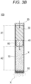
- the main body portion 10 has a proximal portion 12 located on an upstream side (left side in FIG. 1 ) into which a liquid component in a body fluid (extracellular fluid) flows and a distal portion 13 located on a downstream side (right side in FIG. 1 ) from which the substance to be administered X is released to the living body.
- the liquid permeation portion 20, the pressing portion 30, the plug 40, and the release portion 50 are arranged in order from the proximal portion 12 toward the distal portion 13 of the main body portion 10.
- the main body portion 10 has a first space A1 and a second space A2 partitioned by the plug 40.
- the first space A1 is partitioned by the liquid permeation portion 20 and the plug 40, and is a space in which the pressing portion 30 is stored.
- the second space A2 is a space partitioned by the plug 40 and the release portion 50 and in which the substance to be administered X is stored. At least part of the second space A2 constitutes a region where the plug 40 slides.
- Spaces of the first space A1 and the second space A2 are enlarged or reduced as the plug 40 slides before and after the continuous administration device 100 is driven (see FIGS. 3A to 3D ).
- the plug 40 slides toward the downstream side by the pressing portion 30, and an interval gradually increases.
- the plug 40 slides toward the downstream side by the pressing portion 30, and the interval gradually narrows.
- a resin material (acrylonitrile polymers, halogenated polymers, polyimide, polysulfone, polycarbonate, polyethylene, polypropylene, polyvinyl chloride-acrylic acid copolymer, polycarbonate-acrylonitrile-butadienestyrene, polystyrene, and the like) or a metal material (stainless steel, titanium, nickel, aluminum, vanadium, platinum, tantalum, gold, and alloys thereof, and gold plated alloy iron, platinum plated alloy iron, cobalt chromium alloy, titanium nitride-coated stainless steel, and the like) which is non-invasive or minimally invasive to a living body and known in the medical field can be applied.
- a metal material stainless steel, titanium, nickel, aluminum, vanadium, platinum, tantalum, gold, and alloys thereof, and gold plated alloy iron, platinum plated alloy iron, cobalt chromium alloy, titanium nitride-coated stainless steel, and the like
- the liquid permeation portion 20 is disposed on the proximal end side of the main body portion 10, isolates the living body from inside of the continuous administration device 100, and permeates only a liquid component contained in a body fluid in the living body.
- the liquid permeation portion 20 is constituted with a member having a solid-liquid separation function capable of permeating only a liquid component in a body fluid.
- a semipermeable membrane including a plasticized cellulose-based material, reinforced polymethyl methacrylates (PMMA) such as hydroxyl ethyl methacrylate (HEMA), and elastomer materials such as polyurethanes and polyamides, polyether-polyamide copolymers, and thermoplastic copolyesters can be applied as the liquid permeation portion 20.
- PMMA polymethyl methacrylates
- HEMA hydroxyl ethyl methacrylate
- elastomer materials such as polyurethanes and polyamides, polyether-polyamide copolymers, and thermoplastic copolyesters
- the pressing portion 30 is located on the downstream side with respect to the liquid permeation portion 20 in the main body portion 10 and presses the plug 40 toward the downstream side.
- the pressing portion 30 is an osmotic engine that expands by being permeated by the liquid component that has permeated the liquid permeation portion 20 using the principle of osmotic pressure.
- the pressing portion 30 is gradually expanded by the liquid component that has permeated the liquid permeation portion 20 and slides the plug 40 toward the downstream side by pressing action caused by increase in an internal pressure in the first space A1 due to the expansion.
- a constituent material, a size, and the like, of the pressing portion 30 can be appropriately determined so as to achieve a pressing speed (that is, an expansion speed of the pressing portion 30) of the plug 40 according to use conditions (a sustained release period, a release amount per unit time, and the like, of the substance to be administered X).
- the continuous administration device 100 can sustainably release the drug for a long period of time over several years depending on the composition of the osmotic engine constituting the pressing portion 30, a thickness of the semipermeable membrane constituting the liquid permeation portion 20, and the like.
- the plug 40 includes a columnar base portion 41 and an annular protruding portion 42 protruding from a radially outer periphery of the base portion 41.
- the plug 40 is pressed by the pressing portion 30 and moves to the downstream side to push out the substance to be administered X stored in the second space A2 toward the release portion 50.
- the plug 40 is located on the downstream side with respect to the pressing portion 30 in the main body portion 10, has an outer peripheral surface in liquid-tight contact with the inner peripheral surface of the inner cavity 11 of the main body portion 10 and is slidably disposed in the inner cavity 11.
- the protruding portion 42 includes a first protruding portion 42a provided on an outer surface on the proximal end side of the base portion 41, a second protruding portion 42b provided substantially in the middle of the base portion 41, and a third protruding portion 42c provided on the outer surface on the distal end side of the base portion 41.
- An apex portion protruding outermost of the protruding portion 42 abuts on the inner peripheral surface of the inner cavity 11 of the main body portion 10.
- the first protruding portion 42a, the second protruding portion 42b, and the third protruding portion 42c seal between the inner peripheral surface of the inner cavity 11 and the first protruding portion 42a, the second protruding portion 42b, and the third protruding portion 42c so that the substance to be administered X does not leak to the proximal end side with respect to the plug 40.
- the protruding portion 42 includes the first protruding portion 42a, the second protruding portion 42b, and the third protruding portion 42c, the number and arrangement positions thereof are not particularly limited. In addition, it is also possible to employ a configuration where the plug 40 does not include the protruding portion 42.
- the plug 40 As a constituent material of the plug 40, the plug 40 is constituted with a flexible material that has adhesion (liquid tightness) to the inner peripheral surface of the inner cavity 11 of the main body portion 10.
- the flexible material is preferably an elastic material
- examples of the elastic material include various rubber materials (in particular, those subjected to vulcanization treatment) such as natural rubber, isoprene rubber, butyl rubber, chloroprene rubber, nitrile-butadiene rubber, styrene-butadiene rubber, and silicone rubber, styrene-based elastomers, hydrogenated styrene-based elastomers, and styrene-based elastomers mixed with polyolefins such as polyethylene, polypropylene, polybutene, and ⁇ -olefin copolymers, oils such as liquid paraffin and process oil, and powder inorganic substances such as talc, cast, and mica.
- various rubber materials in particular, those subjected to vulcanization treatment
- polyolefins such as polyethylene, polypropylene, polybutene, and ⁇ -olefin copolymers
- oils such as liquid par
- a polyvinyl chloride-based elastomer, an olefin-based elastomer, a polyester-based elastomer, a polyamide-based elastomer, a polyurethane-based elastomer, or a mixture thereof can be used as the constituent material.
- a diene-based rubber, a styrene-based elastomer, or the like can be applied from the viewpoint of having elastic characteristics and enabling ⁇ -ray sterilization, electron beam sterilization, and highpressure steam sterilization.
- the plug 40 only requires to be slidable in the inner cavity 11 in a liquid-tight manner.
- the base portion 41 and the protruding portion 42 of the plug 40 may be constituted with a flexible material or an elastic material, or for example, only the protruding portion 42 abutting on the inner cavity 11 may be constituted with an elastic material, and the base portion 41 may be constituted with a hard material having no elasticity.
- the release portion 50 is disposed on the distal end side of the main body portion 10, and releases the substance to be administered X pushed out by the plug 40 into the living body.
- the release portion 50 has a plurality of through holes penetrating a plate-like member having a predetermined thickness along an axial direction in order to efficiently administer the substance to be administered X into the living body.
- the release portion 50 has a plurality of through holes, so that the substance to be administered X can be diffused into the living body without being solidified at one place. Note that a shape and the number of the through holes formed in the release portion 50 can be appropriately determined in consideration of properties of the c X, ease of diffusion of the substance to be administered X at the place where the continuous administration device 100 is indwelled, and the like.
- the release portion 50 may have a shape having one long spiral flow path on the outer peripheral surface of the cylindrical member from the viewpoint of preventing back diffusion.
- the release portion 50 has the spiral flow path having a length and a flow path width corresponding to a discharge rate of the substance to be administered X, so that it is possible to prevent a biological tissue fluid from being mixed into the substance to be administered X in the second space A2.
- the continuous administration device 100 has the sliding solid coating layer 60 between the inner cavity 11 of the main body portion 10 and the plug 40.
- the sliding solid coating layer 60 reduces initial sliding resistance and normal sliding resistance of the plug 40.
- the sliding solid coating layer 60 is provided on at least one of the outer peripheral surface of the plug 40 or the inner peripheral surface serving as the region where the plug 40 slides in the inner cavity 11 of the main body portion 10.
- the sliding solid coating layer 60 may be formed on the outer peripheral surface of the plug 40 at least at a position in contact with the inner peripheral surface of the inner cavity 11 of the main body portion 10.
- the sliding solid coating layer 60 may be formed at least at a position in contact with the outer peripheral surface of the plug 40 in the region (predetermined region in the second space A2) where the plug 40 slides in the inner cavity 11 of the main body portion 10.
- the sliding solid coating layer 60 is provided on the entire outer peripheral surface of the plug 40.
- the sliding solid coating layer 60 in a case where the sliding solid coating layer 60 is formed in the inner cavity 11 of the main body portion 10, the sliding solid coating layer 60 may be formed only in the periphery of a region where the plug 40 stands by upon start of sliding.
- a lubricating layer other than the sliding solid coating layer 60 of the present invention such as silicone oil may be provided on an inner cavity forming surface of the inner cavity 11 ahead of the sliding solid coating layer 60.
- the initial sliding resistance of the plug 40 can be effectively reduced by the sliding solid coating layer 60, and rapid expression of the effect by the administered substance X can be achieved.
- the initial sliding resistance of the plug 40 can be reduced by the sliding solid coating layer 60 and thus, increase in the internal pressure of the inner cavity 11 until sliding of the plug 40 is started can also be reduced, so that an effect of preventing rapid administration (initial burst) after release of the initial sliding resistance can be expected.
- the sliding solid coating layer 60 is constituted with a material capable of obtaining an effect of reducing the initial sliding resistance and the normal sliding resistance of the plug 40.
- the sliding solid coating layer 60 is formed with a composition (hereinafter, simply referred to as a "silicone-based resin composition") containing a silicone-based resin which is formed with a condensate of reactive silicone having a terminal silanol group and has a siloxane bond derived from the silanol group, or a fluorine-based resin film.
- the sliding solid coating layer 60 may have a configuration in which only one of the silicone-based resin composition or the fluorine-based resin film is employed, or a configuration in which the silicone-based resin composition is provided on one of the outer peripheral surface of the plug 40 or the inner cavity 11 of the main body portion 10 and the fluorine-based resin film is provided on the other.
- the silicone-based resin composition includes a composition containing a silicone-based resin including a condensate of reactive silicone having a terminal silanol group and having a siloxane bond derived from the silanol group, and does not contain solid fine particles.
- a silicone-based resin composition those described in WO 2009/084646 A , WO 2012/133264 A , and the like, can be applied as an example.
- the composition containing a reactive silicone-based resin is preferably a thermosetting silicone-based resin or a room-temperature curable silicone-based resin, and particularly preferably a thermosetting silicone-based resin from the viewpoint of workability, and the like.
- the reactive silicone is preferably polydimethylsiloxane having a terminal silanol group.
- the reactive silicone preferably has silanol groups at both terminals.
- the condensate of the reactive silicone has a siloxane bond in the entire main chain.
- a polysiloxane-based silicone having silanol groups at both terminals such as silanol polydimethylsiloxane at both terminals, silanol polydiphenylsiloxane at both terminals, and silanol diphenylsiloxane-dimethylsiloxane copolymer at both terminals, are suitable.
- a form of the reactive silicone is not particularly limited, but it is also possible to use a product obtained by dispersing, emulsifying, and dissolving a polysiloxane composed of the reactive silicone siloxane compound or a condensate thereof as described above in an aqueous medium, a copolymer emulsion obtained by copolymerizing an alkoxysilyl group-containing vinyl monomer with another vinyl monomer as necessary, an emulsion obtained by complexing a polysiloxane with an organic polymer, and the like.
- the resin composition that forms the sliding solid coating layer 60 preferably contains a second silicone-based compound different from the reactive silicone-based resin having a silanol group or a siloxane bond.
- a second silicone-based compound different from the reactive silicone-based resin having a silanol group or a siloxane bond.
- the second silicone-based compound alkylalkoxysilane, phenylalkoxysilane, alkylphenoxysilane, aminoalkyl alkoxysilane, glycidoxyalkyl alkoxysilane, or the like, is suitable.
- the composition that forms the sliding solid coating layer 60 preferably contains alkyl alkoxysilane or phenyl alkoxysilane as the second silicone-based compound, and further contains aminoalkyl alkoxysilane and/or glycidoxyalkyl alkoxysilane as a third silicone-based compound. More preferably, the resin composition that forms the coating layer contains alkyl alkoxysilane or phenyl alkoxysilane as the second silicone-based compound, further contains aminoalkyl alkoxysilane as the third silicone-based compound, and preferably contains glycidoxyalkyl alkoxysilane as a fourth silicone-based compound.
- the second silicone-based compound is preferably alkyl alkoxysilane, alkyl phenoxysilane, phenyl alkoxysilane, or the like.
- alkyl alkoxysilane methyltrimethoxysilane, methyltriethoxysilane, methyltriisobutoxysilane, methyltributoxysilane, methyl sec-trioctyloxysilane, isobutyltrimethoxysilane, cyclohexylmethyldimethoxysilane, diisopropyldimethoxysilane, propyltrimethoxysilane, diisobutyldimethoxysilane, n-octylmethoxysiloxane, ethyltrimethoxysilane, dimethyldimethoxysilane, octyltriethoxysilane, hexyltrimethoxysilane, hexyltriethoxy
- alkylphenoxysilane for example, methyltriphenoxysilane or the like, is suitable.
- phenoxyalkoxysilane phenyltrimethoxysilane, phenyltriethoxysilane, diphenyldimethoxysilane, diphenyldiethoxysilane, or the like.
- methyltri (glycidyloxy) silane trimethylchlorosilane, dimethylchlorosilane, methyltrichlorosilane, tetraethoxysilane, heptadecafluorodecyltrimethoxysilane, tridecafluorooctyltrimethoxysilane, tetrapropoxirane, or the like, can also be used.
- aminoalkyl alkoxysilane may be used as the second silicone-based compound.
- aminoalkyl alkoxysilane 3-aminopropyltriethoxysilane, 3- (2-aminoethyl) aminopropyltrimethoxysilane, 3- (2-aminoethyl) aminopropylmethyldimethoxysilane, 3-aminopropyltrimethoxysilane, 3-phenylaminopropyltrimethoxysilane, or the like, is suitable.
- glycidoxyalkyl alkoxysilane may be used as the second silicone-based compound.
- glycidoxyalkyl alkoxysilane 3-glycidoxypropyltrimethoxysilane, 3-glycidoxypropyltriethoxysilane, 3-glycidoxypropylmethyldiethoxysilane, 3-glycidoxypropylmethyldimethoxysilane, 2- (3,4-epoxycyclohexyl) ethyltrimethoxysilane, or the like, is suitable.
- a silane-based compound such as 3-ureidopropyltriethoxysilane, diallyldimethylsilane, n-octyldimethylchlorosilane, tetraethoxysilane, or trifluoropropyltrimethoxysilane may be used.
- the composition that forms the sliding solid coating layer 60 may contain the second and third silicone-based compounds.
- the second silicone compound is preferably selected from alkyl alkoxysilanes, alkylphenoxysilane and phenylalkoxysilane.
- the third silicone-based compound aminoalkyl alkoxysilane or glycidoxyalkyl alkoxysilane is preferably used.
- the composition that forms the coating layer may contain the second, third and fourth silicone-based compounds.
- the second silicone compound is preferably selected from alkylalkoxysilane, alkylphenoxysilane, and phenylalkoxysilane.
- the third silicone-based compound is preferably aminoalkyl alkoxysilane
- the fourth silicone-based compound is preferably glycidoxyalkyl alkoxysilane.
- the silicone-based resin composition applicable to the sliding solid coating layer 60 does not contain "solid fine particles".
- solid fine particles refers to particles having a size that affects roughness of the outer surface in a case where the sliding solid coating layer 60 is formed and specifically refers to particles having a particle diameter of more than 10% of the thickness of the sliding solid coating layer 60.
- the sliding solid coating layer 60 is obtained by dispersing and suspending, in purified water, a material obtained by blending a required amount of the above-described silicone-based resin composition with a required composition on the outer peripheral surface of the plug 40 or the inner peripheral surface of the inner cavity 11 of the main body portion 10 on which the sliding solid coating layer 60 is to be formed, and then applying and curing the coating liquid to the outer surface of the clean plug 40 or the inner peripheral surface of the inner cavity 11.
- a method of applying the coating liquid to the outer surface of the plug 40 or the inner peripheral surface of the inner cavity 11 a method known in related art such as an immersion method or a spraying method can be used.
- a method of leaving to stand at room temperature may be used, but heat curing is preferable.
- a thermal curing method is not particularly limited as long as it does not alter or deform a gasket base material, and examples thereof include hot air drying and a drying furnace using infrared rays.
- a method known in related art such as a method using a vacuum dryer may be used.
- the fluorine-based resin film is constituted with a fluorine-based resin that is extremely inert and has chemical resistance, slippage, and adhesion-preventing property.
- PTFE polytetrafluoroethylene
- ETFE ethylenetetrafluoroethylene copolymer
- PFE perfluoroalkoxy alkane
- PFA perfluoroethylene propene copolymer
- PVDF polyvinylidene fluoride
- alloys of these with other polymers, or the like can be applied.
- examples of the fluorine-based resin film those described in JP 2006-181027 A , JP 2007-54621 A , JP 2008-154644 A , JP 2015-70914 A , JP 2015-150377 A , and the like, can be applied.
- a known film forming technique can be appropriately adopted.
- a parylene coat one example is disclosed in JP 2002-177364 A
- a diamondlike carbon (DLC) coat one example is disclosed in JP 2001-190665 A
- a coating material as one example, US 10537273 B
- an organosilicon precursor or the like
- the continuous administration device 100 has the sliding solid coating layer 60 produced by appropriately using the above-described material on at least one of the outer peripheral surface of the plug 40 or the inner peripheral surface serving as the region where the plug 40 slides in the inner cavity 11 of the main body portion 10.
- the sliding solid coating layer 60 has an effect of significantly reducing initial sliding resistance and normal sliding resistance as compared with silicone oil.
- a sustained release rate of the continuous administration device 100 is a rate for releasing the substance to be administered X (drug) filled in the main body portion 10 by a certain amount for a predetermined period, and can be a value obtained by dividing an entire length of a region (corresponding to the region where the plug 40 slides) filled with the substance to be administered X by an administration period (minute).
- a total length of the region filled with the substance to be administered X is 30 mm, it is "0.0015 mm/min” in the case of sustained release for two weeks (elapsed minutes: 20160 minutes), "0.0001 mm/min” in the case of sustained release for 180 days (elapsed minutes: 259200 minutes), and "0.00001 mm/min” in the case of sustained release for five years (elapsed minutes: 2628000 minutes).
- a total length of the region filled with the substance to be administered X is 30 mm, it is "0.0015 mm/min” in the case of sustained release for two weeks (elapsed minutes: 20160 minutes), "0.0001 mm/min” in the case of sustained release for 180 days (elapsed minutes: 259200 minutes), and "0.00001 mm/min” in the case of sustained release for five years (elapsed minutes: 2628000 minutes).
- the plug 40 in order to sustainably release the substance to be administered X over a long period of time, it is necessary to slide the plug 40 at a sliding
- Silicone oil generally used as a lubricant can significantly reduce the normal sliding resistance of the plug 40 as compared with the above-described various materials applicable to the sliding solid coating layer 60 according to the present embodiment at an administration rate in a relatively short period (about several seconds to several tens of minutes) such as bolus administration.
- various materials applicable to the sliding solid coating layer 60 can significantly reduce the initial sliding resistance and the normal sliding resistance of the plug 40 as compared with silicone oil, at a low speed, an extremely low speed, or a super extremely low speed for continuous administration for a long period of time such as several weeks to several months or several years, as described in Examples described later.
- Such a reverse phenomenon of the sliding resistance reduction effect depending on the administration rate (sliding speed of the plug 40) is a phenomenon that the present inventors have found from examination results of Examples described in detail later through search for a material that can significantly reduce the initial sliding resistance and the normal sliding resistance of the plug 40.
- the continuous administration device 100 including the sliding solid coating layer 60, the initial sliding resistance and the normal sliding resistance of the plug 40 are reduced and a period until the drug discharge start time is shortened in a case where the substance to be administered X is continuously administered at an administration rate of a low speed to an extremely low speed and a super extremely low speed for a long period of time.
- the continuous administration device 100 can accelerate time until the effect by the administration of the administered substance X is expressed.
- the continuous administration device 100 is indwelled in the living body after being filled with the substance to be administered X to the administration target.
- a state of the continuous administration device 100 is a state before the liquid component of the body fluid permeates the liquid permeation portion 20, and thus, the pressing portion 30 is not expanded, and sliding of the plug 40 is not started.
- the liquid component in the body fluid permeates into the liquid permeation portion 20.
- the pressing portion 30 starts to expand by the liquid component that has permeated from the liquid permeation portion 20.
- the plug 40 starts sliding toward the downstream side of the second space A2 as a result of the internal pressure of the inner cavity 11 increasing as the pressing portion 30 expands.
- the sliding solid coating layer 60 is provided on the outer peripheral surface of the plug 40, and thus, the initial sliding resistance is significantly reduced, and the plug 40 starts to slide in a short period of time.
- the plug 40 in the continuous administration device 100, if sliding shifts to normal sliding after initial sliding, the plug 40 gradually slides to the downstream side. In this event, the plug 40 slides to the downstream side at a substantially constant sliding speed so that a prescribed amount of the substance to be administered X is continuously administered for a long period of time.
- the continuous administration device 100 sliding of the plug 40 is stopped in accordance with end time of the administration period of the substance to be administered X. As illustrated in FIG. 3D , a distal end of the plug 40 is in contact with a surface on the proximal end side of the release portion 50. If the administration period of the substance to be administered X ends, the continuous administration device 100 is extracted from the living body.
- the continuous administration device 100 is a device that includes the cylindrical main body portion 10 having the inner cavity 11, the plug 40 slidable in the inner cavity 11 in a liquid-tight manner, the pressing portion 30 disposed on the upstream side with respect to the plug 40 in the inner cavity 11 and pressing the plug 40 toward the downstream side, and the substance to be administered X stored on the downstream side with respect to the plug 40 in the inner cavity 11 and released into the living body by the plug 40 sliding toward the downstream side, and is indwelled in the living body for sustained release of the substance to be administered X.
- the continuous administration device 100 includes the sliding solid coating layer 60 formed with a silicone-based resin composition or a fluorine-based resin film for reducing initial sliding resistance and normal sliding resistance of the plug 40, on at least one of the outer surface of the plug 40 or the region where the plug 40 slides in the inner cavity 11.
- the sliding solid coating layer 60 has an effect of significantly reducing initial sliding resistance and normal sliding resistance as compared with silicone oil when sliding is performed at a low speed, an extremely low speed, or a super extremely low speed.
- the continuous administration device 100 continuously administers the substance to be administered X at a low speed, an extremely low speed, or a super extremely low speed for a long period of time, the initial sliding resistance and the normal sliding resistance of the plug 40 are reduced, and a period until the drug discharge start time is shortened.
- the continuous administration device 100 can accelerate time until the effect by the administration of the administered substance X is expressed.
- the continuous administration device 100 has been described with a configuration in which the osmotic engine that expands by the liquid component of the body fluid in the living body is used as the configuration of the pressing portion 30 that presses the plug 40.
- the configuration of the pressing portion 30 is not limited to the osmotic engine, and for example, a mechanical configuration using a motor as a drive source can also be adopted.
- the sliding solid coating layer 60 is provided on one of the outer surface of the plug 40 or the region where the plug 40 slides in the inner cavity 11, so that the effect of significantly reducing the initial sliding resistance and the normal sliding resistance of the plug 40 can be obtained.
- a tensile/compression tester “EZ-test (manufactured by Shimadzu Corporation)” was used.
- a 1 ml syringe “PLAJEX Luer lock type (manufactured by TERUMO CORPORATION)” equipped with a gasket (corresponding to the plug) having a peak (corresponding to the protruding portion) was used in a state where a needle was not attached.
- Example 1 As a lubricant coated on the outer surface of the gasket of the syringe, in Example 1, a silicone-based resin composition applicable to the sliding solid coating layer according to the present embodiment was used, and in Example 2, a fluorine-based resin film applicable to the sliding solid coating layer according to the present embodiment was used.
- silicone oil "360 Medical Fluid 12500 (manufactured by Dow Corning Toray Co., Ltd.)" was used. Each sample corresponding to Example 1, Example 2, and Comparative Example 1 was prepared by coating the gasket with each of these lubricants and then capping the gasket. Note that in Comparative Example 1, storage was performed under severe conditions (60 °C for one week) in order to reproduce a sticking state which is a problem of the silicone oil.
- An examination speed is a speed at which a pusher of the syringe is pressed.
- the examination speed was set to three speeds of an extremely low administration rate "speed 1: 0.01 mm/min" for the purpose of long-term sustained release, a normal administration rate “speed 3: 200 mm/min” corresponding to bolus administration, and a low administration rate "speed 2: 1 mm/min” which is intermediate between speed 1 and speed 3.
- Table 1 indicates results of initial sliding resistance value (N) and normal sliding resistance value (N) at each examination speed in Example 1, Example 2, and Comparative Example 1.
- the "initial sliding resistance” in the table is a maximum value (upper yield point) when the plug yields while the plug starts sliding and shifts to normal sliding.
- the "normal sliding resistance” in the table is a maximum value when sliding of the plug shifts to the normal sliding after the initial sliding.
- the initial sliding resistance of Example 1 and Example 2 was smaller than the initial sliding resistance of Comparative Example 1, and the normal sliding resistance was also smaller than that of Comparative Example 1.
- the initial sliding resistance of Example 1 and Example 2 was smaller than the initial sliding resistance of Comparative Example 1, and the normal sliding resistance was also smaller than that of Comparative Example 1.
- the initial sliding resistance of Example 1 and Example 2 was smaller than the initial sliding resistance of Comparative Example 1, and the normal sliding resistance was higher than that of Comparative Example 1.
- both the silicone-based resin composition and the fluorine-based resin film which are materials applicable to the sliding solid coating layer according to the present embodiment, significantly reduce the initial sliding resistance and the normal sliding resistance of the plug at a low administration rate of 1 mm/min or less and an extremely low administration rate.
- a container sample serving as the main body portion a container sample having the same specification as the syringe used in Examination 1 was used.
- a lubricant for coating the outer surface of the gasket of the syringe a silicone-based resin composition "i-coating (manufactured by Terumo Corporation)" applicable to the sliding solid coating layer according to the present embodiment was used as Example 1, and a fluorine-based resin film applicable to the sliding solid coating layer according to the present embodiment was used as Example 2.
- silicone oil "360 Medical Fluid 12500 (manufactured by Dow Corning Toray Co., Ltd.)” was used. Note that in Comparative Example 1, storage was performed under severe conditions (60 °C for one week) in order to reproduce a sticking state which is a problem of the silicone oil.
- Example 1 Example 2, and Comparative Example 1 were applied as lubricants to the outer surface of the gasket, the gasket was capped with the syringe.
- Sodium chloride was filled at a terminal of the syringe as the pressing portion (osmotic engine), and then the syringe was filled with PEG 400 (polyethylene glycol 400) to eliminate air in the syringe.
- PEG 400 polyethylene glycol 400
- Each sample was obtained by plugging the terminal of the syringe with a semipermeable membrane "Winding CELLOFAN (manufactured by HEICO PACK CO., LTD.)" as the liquid permeation portion. These samples were immersed in water at normal temperature, and a period until the sliding start time of the gasket was measured.
- Table 2 indicates results of periods until the sliding start time (min) in Example 1, Example 2, and Comparative Example 1. [Table 2] Period until sliding start time (min) Example 1 44.5 Example 2 54.8 Comparative Example 1 140.9
- Example 1 As indicated in Table 2, the period until the sliding start time (Example 1: 44.5 min, Example 2: 54.8 min) of the gasket in each of Example 1 and Example 2 was shortened to about 1/3 as compared with the period until the sliding start time (140.9 minutes) of Comparative Example 1. From the above, it was confirmed that Example 1 and Example 2 significantly reduced the initial sliding resistance as compared with Comparative Example 1. Thus, it has been proved that the silicone-based resin composition and the fluorine-based resin film, which are materials applicable to the sliding solid coating layer according to the present embodiment, significantly reduce the initial sliding resistance of the plug.
- a tensile/compression tester “EZ-test (manufactured by Shimadzu Corporation)" was used.
- a metal pipe including a release portion at a distal end and a gasket (corresponding to the plug) having a peak (corresponding to the protruding portion) on the outer peripheral surface was used. Materials and dimensions of each component are indicated below.
- Example 3 As the lubricant with which the outer surface of the gasket of the pipe was coated, the silicone-based resin composition applicable to the sliding solid coating layer according to the present embodiment was used in Example 3, and silicone oil "360 Medical Fluid 12500 (manufactured by Dow Corning Toray Co., Ltd.)" was used in Comparative Example 2.
- silicone oil "360 Medical Fluid 12500 (manufactured by Dow Corning Toray Co., Ltd.)" was used in Comparative Example 2.
- Comparative Example 2 Each of samples corresponding to Example 3 and Comparative Example 2 was prepared by coating the gasket with each of these lubricants and then capping the gasket.
- storage was performed under severe conditions (60 °C for one week) in order to reproduce a sticking state which is a problem of the silicone oil.
- An examination speed (pressing speed) was set to "speed 4: 0.001 mm/min", which is the lowest speed that can be implemented by the examination equipment.
- Table 3 indicates results of an initial sliding resistance value (N) and a normal sliding resistance value (N) at each examination speed in Example 3 and Comparative Example 2.
- the "initial sliding resistance” and the "normal sliding resistance” in the tables are synonymous with the respective terms indicated in Table 1.
- Speed 4 (0.001 mm/min) Initial sliding (N) Normal sliding (N) Example 3 2.3 0.6 Comparative Example 2 3.6 4.5
- Example 3 As indicated in Table 3, in a case where sliding was performed at speed 4 with Example 3 and Comparative Example 2, the initial sliding resistance of Example 3 was smaller than the initial sliding resistance of Comparative Example 2, and the normal sliding resistance was also smaller than that of Comparative Example 2.
- Example 3 significantly reduced the initial sliding resistance and the normal sliding resistance as compared with Comparative Example 2.
- the sliding solid coating layer exhibits an effect of reducing initial sliding resistance by about 60% as compared with silicone oil.
Applications Claiming Priority (2)
| Application Number | Priority Date | Filing Date | Title |
|---|---|---|---|
| JP2021051366 | 2021-03-25 | ||
| PCT/JP2022/013404 WO2022202881A1 (ja) | 2021-03-25 | 2022-03-23 | 持続投与装置 |
Publications (1)
| Publication Number | Publication Date |
|---|---|
| EP4302800A1 true EP4302800A1 (en) | 2024-01-10 |
Family
ID=83397296
Family Applications (1)
| Application Number | Title | Priority Date | Filing Date |
|---|---|---|---|
| EP22775663.2A Pending EP4302800A1 (en) | 2021-03-25 | 2022-03-23 | Continuous administration device |
Country Status (4)
| Country | Link |
|---|---|
| US (1) | US20240016728A1 (ja) |
| EP (1) | EP4302800A1 (ja) |
| JP (1) | JPWO2022202881A1 (ja) |
| WO (1) | WO2022202881A1 (ja) |
Family Cites Families (20)
| Publication number | Priority date | Publication date | Assignee | Title |
|---|---|---|---|---|
| JP3430014B2 (ja) | 1997-06-04 | 2003-07-28 | 信越化学工業株式会社 | 水性シリコーン組成物 |
| DE69910982T2 (de) | 1998-03-06 | 2004-07-15 | Novo Nordisk A/S | Medizinischer artikel mit beschichteter oberfläche mit niedriger reibung und geringer eiweissadsorption |
| JP4230664B2 (ja) | 1998-03-17 | 2009-02-25 | ベクトン・ディキンソン・アンド・カンパニー | 薬剤供給装置用シーリング部材及びそれを具えた薬剤供給装置 |
| JP4144019B2 (ja) | 2000-01-07 | 2008-09-03 | ニプロ株式会社 | 穿刺針 |
| JP2001190665A (ja) | 2000-01-14 | 2001-07-17 | Terumo Corp | シリンジ |
| JP4698020B2 (ja) | 2000-12-19 | 2011-06-08 | テルモ株式会社 | 薬剤収納容器 |
| US6595961B2 (en) | 2001-04-16 | 2003-07-22 | Becton, Dickinson And Company | Sterilizable transfer or storage device for medicaments, drugs and vaccines |
| US7332227B2 (en) | 2003-03-14 | 2008-02-19 | Becton, Dickinson And Company | Non-volatile lubricant system for medical devices |
| JP2006181027A (ja) | 2004-12-27 | 2006-07-13 | Daikyo Seiko Ltd | 注射器用ピストン |
| JP5279994B2 (ja) | 2005-07-28 | 2013-09-04 | 株式会社大協精工 | 医療用ゴム製品 |
| JP2007244606A (ja) | 2006-03-15 | 2007-09-27 | Hisamitsu Pharmaceut Co Inc | シリンジ、及びシリンジの製造方法 |
| US8075995B2 (en) | 2006-03-30 | 2011-12-13 | Becton, Dickinson And Company | Coating system, articles and assembly using the same and methods of reducing sticktion |
| JP4860455B2 (ja) | 2006-12-21 | 2012-01-25 | 日東電工株式会社 | シリンジ用ガスケットとこれを用いたシリンジならびにガスケット用摺動フィルム |
| WO2009084646A1 (ja) | 2007-12-28 | 2009-07-09 | Terumo Kabushiki Kaisha | シリンジ用ガスケットおよびそれを備えたシリンジ |
| MX345403B (es) | 2009-05-13 | 2017-01-30 | Sio2 Medical Products Inc | Revestimiento por pecvd utilizando un precursor organosilícico. |
| JP5718925B2 (ja) | 2009-09-28 | 2015-05-13 | インターシア セラピューティクス,インコーポレイティド | 実質的な定常状態薬物送達の迅速な確立及び/又は停止 |
| JP5898675B2 (ja) | 2011-03-30 | 2016-04-06 | テルモ株式会社 | 摺動性被覆層保有医療用具およびシリンジ |
| JP6317086B2 (ja) | 2013-10-02 | 2018-04-25 | 住友ゴム工業株式会社 | プレフィルドシリンジ用ガスケット |
| JP6270266B2 (ja) | 2014-02-19 | 2018-01-31 | 住友ゴム工業株式会社 | プレフィルドシリンジ用ガスケットおよびプレフィルドシリンジ |
| JP7272210B2 (ja) | 2019-09-20 | 2023-05-12 | 株式会社Jvcケンウッド | 携帯端末 |
-
2022
- 2022-03-23 JP JP2023509237A patent/JPWO2022202881A1/ja active Pending
- 2022-03-23 EP EP22775663.2A patent/EP4302800A1/en active Pending
- 2022-03-23 WO PCT/JP2022/013404 patent/WO2022202881A1/ja active Application Filing
-
2023
- 2023-09-22 US US18/472,929 patent/US20240016728A1/en active Pending
Also Published As
| Publication number | Publication date |
|---|---|
| JPWO2022202881A1 (ja) | 2022-09-29 |
| WO2022202881A1 (ja) | 2022-09-29 |
| US20240016728A1 (en) | 2024-01-18 |
Similar Documents
| Publication | Publication Date | Title |
|---|---|---|
| EP1870117B1 (en) | Medical appliance coating composition and medical appliance | |
| EP2554205B1 (en) | Medical device with slideable coating, and syringe | |
| ES2373585T3 (es) | Miembros de sellado, artículos que usan los mismos y procedimientos de reducir fricción estática. | |
| ES2669447T3 (es) | Sistema de recubrimiento, artículos y conjunto utilizando los mismos y procedimientos para reducir la adherencia | |
| US10384008B2 (en) | Syringe with needle, prefilled syringe, and medical liquid administration tool using the same | |
| EP2692366B1 (en) | Medical instrument with slidable coating layer, and syringe | |
| US8802603B2 (en) | Medical components having coated surfaces exhibiting low friction and low reactivity | |
| CN112657021A (zh) | 具有层压塞的药物递送装置 | |
| KR20160005735A (ko) | 안구용 주사를 위한 장치 및 방법 | |
| KR20150023052A (ko) | 의료용 주입 장치 | |
| CN112312946A (zh) | 具有抑制氧气渗透的医疗递送设备 | |
| EP4302800A1 (en) | Continuous administration device | |
| EP3437665A1 (en) | Liquid material for medical device coating and medical device having sliding coating film | |
| JP5118385B2 (ja) | 薬液の滅菌方法、並びにプレフィルドシリンジ及びその製造方法 | |
| JP5998337B2 (ja) | コネクタ及びシリコーンゴム製のコネクタ用弁体 |
Legal Events
| Date | Code | Title | Description |
|---|---|---|---|
| STAA | Information on the status of an ep patent application or granted ep patent |
Free format text: STATUS: THE INTERNATIONAL PUBLICATION HAS BEEN MADE |
|
| PUAI | Public reference made under article 153(3) epc to a published international application that has entered the european phase |
Free format text: ORIGINAL CODE: 0009012 |
|
| STAA | Information on the status of an ep patent application or granted ep patent |
Free format text: STATUS: REQUEST FOR EXAMINATION WAS MADE |
|
| 17P | Request for examination filed |
Effective date: 20231002 |
|
| AK | Designated contracting states |
Kind code of ref document: A1 Designated state(s): AL AT BE BG CH CY CZ DE DK EE ES FI FR GB GR HR HU IE IS IT LI LT LU LV MC MK MT NL NO PL PT RO RS SE SI SK SM TR |