EP4301665B1 - Behälter, der unter verwendung eines formungssystems hergestellt ist, und entsprechendes herstellungsverfahren - Google Patents
Behälter, der unter verwendung eines formungssystems hergestellt ist, und entsprechendes herstellungsverfahren Download PDFInfo
- Publication number
- EP4301665B1 EP4301665B1 EP22711102.8A EP22711102A EP4301665B1 EP 4301665 B1 EP4301665 B1 EP 4301665B1 EP 22711102 A EP22711102 A EP 22711102A EP 4301665 B1 EP4301665 B1 EP 4301665B1
- Authority
- EP
- European Patent Office
- Prior art keywords
- container
- containment
- containment body
- moulding
- tubular element
- Prior art date
- Legal status (The legal status is an assumption and is not a legal conclusion. Google has not performed a legal analysis and makes no representation as to the accuracy of the status listed.)
- Active
Links
Images



Classifications
-
- B—PERFORMING OPERATIONS; TRANSPORTING
- B65—CONVEYING; PACKING; STORING; HANDLING THIN OR FILAMENTARY MATERIAL
- B65D—CONTAINERS FOR STORAGE OR TRANSPORT OF ARTICLES OR MATERIALS, e.g. BAGS, BARRELS, BOTTLES, BOXES, CANS, CARTONS, CRATES, DRUMS, JARS, TANKS, HOPPERS, FORWARDING CONTAINERS; ACCESSORIES, CLOSURES, OR FITTINGS THEREFOR; PACKAGING ELEMENTS; PACKAGES
- B65D1/00—Rigid or semi-rigid containers having bodies formed in one piece, e.g. by casting metallic material, by moulding plastics, by blowing vitreous material, by throwing ceramic material, by moulding pulped fibrous material or by deep-drawing operations performed on sheet material
- B65D1/09—Ampoules
- B65D1/095—Ampoules made of flexible material
-
- B—PERFORMING OPERATIONS; TRANSPORTING
- B29—WORKING OF PLASTICS; WORKING OF SUBSTANCES IN A PLASTIC STATE IN GENERAL
- B29C—SHAPING OR JOINING OF PLASTICS; SHAPING OF MATERIAL IN A PLASTIC STATE, NOT OTHERWISE PROVIDED FOR; AFTER-TREATMENT OF THE SHAPED PRODUCTS, e.g. REPAIRING
- B29C49/00—Blow-moulding, i.e. blowing a preform or parison to a desired shape within a mould; Apparatus therefor
- B29C49/42—Component parts, details or accessories; Auxiliary operations
- B29C49/4273—Auxiliary operations after the blow-moulding operation not otherwise provided for
- B29C49/42808—Filling the article
- B29C49/42809—Filling the article while in the mould, i.e. with other material than the blowing fluid
-
- B—PERFORMING OPERATIONS; TRANSPORTING
- B29—WORKING OF PLASTICS; WORKING OF SUBSTANCES IN A PLASTIC STATE IN GENERAL
- B29C—SHAPING OR JOINING OF PLASTICS; SHAPING OF MATERIAL IN A PLASTIC STATE, NOT OTHERWISE PROVIDED FOR; AFTER-TREATMENT OF THE SHAPED PRODUCTS, e.g. REPAIRING
- B29C49/00—Blow-moulding, i.e. blowing a preform or parison to a desired shape within a mould; Apparatus therefor
- B29C49/42—Component parts, details or accessories; Auxiliary operations
- B29C49/4273—Auxiliary operations after the blow-moulding operation not otherwise provided for
- B29C49/42808—Filling the article
-
- B—PERFORMING OPERATIONS; TRANSPORTING
- B65—CONVEYING; PACKING; STORING; HANDLING THIN OR FILAMENTARY MATERIAL
- B65D—CONTAINERS FOR STORAGE OR TRANSPORT OF ARTICLES OR MATERIALS, e.g. BAGS, BARRELS, BOTTLES, BOXES, CANS, CARTONS, CRATES, DRUMS, JARS, TANKS, HOPPERS, FORWARDING CONTAINERS; ACCESSORIES, CLOSURES, OR FITTINGS THEREFOR; PACKAGING ELEMENTS; PACKAGES
- B65D1/00—Rigid or semi-rigid containers having bodies formed in one piece, e.g. by casting metallic material, by moulding plastics, by blowing vitreous material, by throwing ceramic material, by moulding pulped fibrous material or by deep-drawing operations performed on sheet material
- B65D1/02—Bottles or similar containers with necks or like restricted apertures, designed for pouring contents
- B65D1/0223—Bottles or similar containers with necks or like restricted apertures, designed for pouring contents characterised by shape
- B65D1/023—Neck construction
- B65D1/0238—Integral frangible closures
-
- B—PERFORMING OPERATIONS; TRANSPORTING
- B65—CONVEYING; PACKING; STORING; HANDLING THIN OR FILAMENTARY MATERIAL
- B65D—CONTAINERS FOR STORAGE OR TRANSPORT OF ARTICLES OR MATERIALS, e.g. BAGS, BARRELS, BOTTLES, BOXES, CANS, CARTONS, CRATES, DRUMS, JARS, TANKS, HOPPERS, FORWARDING CONTAINERS; ACCESSORIES, CLOSURES, OR FITTINGS THEREFOR; PACKAGING ELEMENTS; PACKAGES
- B65D1/00—Rigid or semi-rigid containers having bodies formed in one piece, e.g. by casting metallic material, by moulding plastics, by blowing vitreous material, by throwing ceramic material, by moulding pulped fibrous material or by deep-drawing operations performed on sheet material
- B65D1/02—Bottles or similar containers with necks or like restricted apertures, designed for pouring contents
- B65D1/04—Multi-cavity bottles
-
- B—PERFORMING OPERATIONS; TRANSPORTING
- B29—WORKING OF PLASTICS; WORKING OF SUBSTANCES IN A PLASTIC STATE IN GENERAL
- B29C—SHAPING OR JOINING OF PLASTICS; SHAPING OF MATERIAL IN A PLASTIC STATE, NOT OTHERWISE PROVIDED FOR; AFTER-TREATMENT OF THE SHAPED PRODUCTS, e.g. REPAIRING
- B29C49/00—Blow-moulding, i.e. blowing a preform or parison to a desired shape within a mould; Apparatus therefor
- B29C49/42—Component parts, details or accessories; Auxiliary operations
- B29C49/46—Component parts, details or accessories; Auxiliary operations characterised by using particular environment or blow fluids other than air
- B29C2049/4602—Blowing fluids
- B29C2049/465—Blowing fluids being incompressible
- B29C2049/4664—Blowing fluids being incompressible staying in the final article
-
- B—PERFORMING OPERATIONS; TRANSPORTING
- B65—CONVEYING; PACKING; STORING; HANDLING THIN OR FILAMENTARY MATERIAL
- B65D—CONTAINERS FOR STORAGE OR TRANSPORT OF ARTICLES OR MATERIALS, e.g. BAGS, BARRELS, BOTTLES, BOXES, CANS, CARTONS, CRATES, DRUMS, JARS, TANKS, HOPPERS, FORWARDING CONTAINERS; ACCESSORIES, CLOSURES, OR FITTINGS THEREFOR; PACKAGING ELEMENTS; PACKAGES
- B65D23/00—Details of bottles or jars not otherwise provided for
- B65D23/12—Means for the attachment of smaller articles
- B65D23/14—Means for the attachment of smaller articles of tags, labels, cards, coupons, decorations or the like
-
- B—PERFORMING OPERATIONS; TRANSPORTING
- B65—CONVEYING; PACKING; STORING; HANDLING THIN OR FILAMENTARY MATERIAL
- B65D—CONTAINERS FOR STORAGE OR TRANSPORT OF ARTICLES OR MATERIALS, e.g. BAGS, BARRELS, BOTTLES, BOXES, CANS, CARTONS, CRATES, DRUMS, JARS, TANKS, HOPPERS, FORWARDING CONTAINERS; ACCESSORIES, CLOSURES, OR FITTINGS THEREFOR; PACKAGING ELEMENTS; PACKAGES
- B65D2501/00—Containers having bodies formed in one piece
- B65D2501/0009—Bottles or similar containers with necks or like restricted apertures designed for pouring contents
- B65D2501/0054—Lines of weakness
Definitions
- the present invention relates to a container made using a system for moulding containers and a related manufacturing method.
- BFS Blow Fill Seal
- the aforementioned BFS moulding technique consists of different consecutive steps, in detail: the step of moulding the container, called “Blow”, the step of filling it, called “Fill', and the step of its hermetic closure by sealing, called “Seal'.
- the container body is first moulded, then loaded/filled with the desired liquid or solid content, and subsequently sealed.
- the first method consists in using the lower part of a forming mould, for the creation of the containment bodies 1 and the bottoms 2 of the container wherein, after the step of filling it, the mould is closed at the related upper head 3, thus making the openings 4 of the container.
- the second method consists in using the lower part of the forming mould to create the containment bodies 1 of the container and the related opening parts 4; after the filling step, the mould is closed at the upper head 3, sealing the container at the related bottoms 2.
- the container is intended as a matrix of containment bodies 1 adjacent to each other and detachable.
- Document KR 102180246 B1 discloses a moulded container according to the preamble of claim 1.
- a problem of the aforementioned moulding/forming technique is that the shape of the containers is constrained by the volume of substance they must contain inside and, therefore, by the number of shapes of containers that can be made over a useful width of the forming mould.
- the main aim of the invention is to propose a container made using a system for moulding containers and a related manufacturing method, which overcomes the drawbacks of the known technique.
- the aim of the invention is to manufacture a container which comprises, for example, an opening which is larger compared to the prior art and which, at the same time, is moulded in such a way as to optimise the use of the available space, to manufacture a maximum number of container shapes.
- a further advantage of the present invention is to show a system for moulding containers such as to allow the manufacturing of a container which is easier to open and to empty compared to known containers having the same moulding interaxis.
- Still another aim of the present invention is to realise a system for moulding containers such as to allow the creation of containers having volumes that can vary according to the request.
- the aim of the present invention is to realise a system for moulding containers which provides and allows the making of labels, engravings, identifications and coupling points for the container itself.
- the object of the invention is a container moulded, advantageously, from a tubular element, for example, made of plastic material, able to contain and dispense at least one solid or fluid substance.
- the container object of the present invention has a longitudinal axis and comprises at least two hollow containment bodies wherein the first hollow containment body is oriented according to a first orientation direction, with respect to the aforementioned longitudinal axis.
- the second containment body is moulded so as to be adjacent to the first containment body, and is oriented according to a second orientation direction, opposite to the aforementioned first orientation direction of the first containment body.
- the container object of the present invention can comprise a central or median zone of variable volume and capable of increasing the capacity of each one of the containment bodies.
- the containment bodies comprise respective first ends, opposite to each other and corresponding to their respective opening sides, and respective second ends, opposite to the aforementioned first ends, such as to advantageously act as the bottom of the containment bodies.
- first or second ends there may be panels that are integrally moulded therewith, preferably for the application of labels or engravings.
- the aforementioned panels can have a substantially polygonal and flat shape and are moulded in correspondence with an empty portion between the second ends of the hollow bodies on which they are moulded, and a further empty portion at the first ends of the adjacent hollow body, in such a way to optimise the use of the moulding space.
- each of the aforementioned containment bodies can comprise, integrally moulded therewith and at the first ends, a hollow coupling means such as to act, both as an accessory for the coupling and as a twist off tab for the opening of the containment bodies.
- containment bodies have a substantially longitudinal shape and can comprise at least a tapered portion.
- the aforementioned container can be moulded using the BFS or blowing technique called Blow moulding, using a system for moulding containers and a mould included therein.
- the container object of the present invention moulded using the aforementioned moulding system, can be made using a manufacturing method comprising the following steps:
- the method described so far allows, advantageously, to manufacture containers that are empty inside and closed only at one end.
- the method described herein can comprise a further step of closing the second end of the container, opposite to the first end of the tubular element, so that each containment body is in an inverted position with respect to the adjacent containment body.
- the container 10 is a matrix of containing bodies 11 adjacent to each other and individually detachable.
- the container 10, object of the present invention advantageously has a longitudinal axis X, perpendicular thereto.
- the moulding system comprises all the devices for manufacturing containers using the blow moulding or the BFS method and, in particular, a mould suitable for making the containers 10, from a tubular element, having at least one hollow containment body 11 such as, by way of example only, a dispensing vial.
- each containment body 11 is able to contain at least one solid or fluid substance such as, for example, a product of a medical type.
- each hollow containment body 11 can have a substantially longitudinal and tapered shape, for example, conical, and is made of tubular elements in materials for example of plastic type, such as to be subject to BFS or Blow moulding processes.
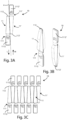
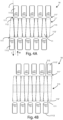
- the moulding system makes it possible to manufacture a hollow body 11 having a first orientation direction L with respect to the longitudinal axis X of the container 10 ( Figures 3A , 4A and 6A ).
- orientation direction or simply “orientation” of the hollow containment body 11, herein we mean the direction towards which the opening of the hollow body 11 itself faces for dispensing.
- the containment body 11 comprising a first end 111, at the opening side of the containment body 11, and from which the substance contained therein will be dispensed, and a second end 112 at the base of the containment body 11 in object, opposite to the aforementioned first end 111, in such a way as to act as the bottom of the containment body 11.
- each hollow body 11 advantageously has, at the first end 111, a tab 1112 of the twist-off type which can be detached to allow its opening and the dispensing of what is contained therein, by rotating it.
- the removal through rotation of each tab 1112 from the related containment body 11 takes place individually for each hollow body 11 and therefore independently from the remaining hollow bodies 11 or 11' which constitute the container 10, facilitating the use of the containment body 11 in object.
- the moulding system is such as to allow, starting from each containment body 11, the moulding of the containment body 11' adjacent thereto, having a second orientation direction M ( Figures 3A , 4A and 6A ) opposite to the first orientation direction L for the manufacturing of the container 10.
- this characteristic allows to have, with the same interaxis between each hollow body 11 and 11', a greater space between two openings having the same orientation compared to that obtainable according to the methods used in the prior art, optimizing the use of the useful moulding spaces.
- the configuration with the vials tapered towards the bottom allows to also have larger openings, which allow to obtain all the advantages this brings, for example to dispense larger drops of the contained substance, this being also valid for more viscous substances, or to access with larger connectors.
- the mould 51 making part of the moulding system is such as to mould each containment body 11 in an overturned manner with respect to the adjacent containment body 11' consequently, the first and second ends 111 and 111', 112 and 112' respectively of each containment body 11 are inverted with each other, advantageously optimising the use of the useful moulding space available and effectively increasing the interaxis between openings facing the same direction.
- the mould 51 of the moulding system in object will form, by way of example, a first containment body 11 with the opening 111 facing towards a first direction and a second containment body 11' adjacent to the first containment body 11, with the opening 111' facing towards a second direction, opposite to the first direction.
- the mould through a median portion of variable length, is such as to allow a variation in the volume of the container 10 in its entirety, depending on the request, by lengthening the central or median area 113 ( Fig. 4B ) and consequently increasing the capacity of each individual containment body 11, while not exceeding the given useful moulding space of the moulding system.
- the containing bodies 11 and 11' in addition to including what is described in the previous embodiments, comprise, at the respective second ends 112 and 112', a panel 1121 and 1121' integrally moulded therewith.
- the aforementioned panels 1121 and 1121' have a substantially polygonal and flat shape such as to be placed and fit perfectly into the otherwise empty spaces of the mould, for example, in correspondence of the area between the second ends 112 and 112' of the hollow bodies 11 and 11', on which they are directly moulded, and the area corresponding to the first ends 111' and 111 of the hollow bodies 11' and 11 adjacent thereto, in such a way as to optimise the use of the useful moulding space, for example, for the application of labels, engravings, etc.
- the containment bodies 11 and 11' comprise, at their first ends 111 and 111', and integrally moulded therewith, hollow coupling means 1113 such as to act both as an accessory for coupling the container 10, for each containment body 11 or 11', and as a twist off tab, for opening the respective containment body 11.
- the method for manufacturing the container 10, for example, when it is carried out using the Blow moulding system includes the following steps:
- containers will then be made closed only at one end and empty inside.
- the filling takes place at the respective second end 112 and the first end 111', by means of nozzles 52, through the still open portion 51 of the mould ( Figure 7 ), in particular before the step of closing the second end of the container 10.
Landscapes
- Engineering & Computer Science (AREA)
- Mechanical Engineering (AREA)
- Ceramic Engineering (AREA)
- Manufacturing & Machinery (AREA)
- Containers Having Bodies Formed In One Piece (AREA)
- Packaging For Recording Disks (AREA)
- Auxiliary Devices For And Details Of Packaging Control (AREA)
- Blow-Moulding Or Thermoforming Of Plastics Or The Like (AREA)
Claims (11)
- Behälter (10), der aus einem rohrförmigen Element geformt ist, das in der Lage ist, mindestens eine feste oder flüssige Substanz aufzunehmen und abzugeben, wobei der Behälter (10) eine Längsachse (X) aufweist und mindestens zwei hohle Aufnahmekörper (11, 11') umfasst, wobei der erste hohle Aufnahmekörper (11) gemäß einer ersten Orientierungsrichtung (L) in Bezug auf die Achse (X) ausgerichtet ist,
dadurch gekennzeichnet, dass der zweite Einschließungskörper (11') so geformt ist, dass er an den ersten Einschließungskörper (11) angrenzt und eine Zwischenachse zwischen dem ersten Einschließungskörper (11) und dem zweiten Einschließungskörper (11') bildet, wobei der zweite Einschließungskörper (11') gemäß einer zweiten Ausrichtungsrichtung (M) ausgerichtet ist, die der ersten Ausrichtungsrichtung (L) des ersten Einschließungskörpers (11) entgegengesetzt ist. - Behälter (10) nach Anspruch 1, dadurch gekennzeichnet, dass die Aufnahmekörper (11; 11') jeweilige erste Enden (111; 111') aufweisen, die einander gegenüberliegen und den jeweiligen Öffnungsseiten der Aufnahmekörper (11; 11') entsprechen, und jeweilige zweite Enden (112; 112'), die den ersten Enden (111; 111') gegenüberliegen, so dass sie als Boden der Behälterkörper (11; 11') dienen, wobei in Übereinstimmung mit den zweiten Enden (112; 112') Platten (1121; 1121') vorhanden sind, die integral mit den zweiten Enden (112; 112') geformt sind, um Etiketten oder Gravuren anzubringen.
- Behälter (10) nach dem vorhergehenden Anspruch, dadurch gekennzeichnet, dass die Tafeln (1121; 1121') eine im Wesentlichen polygonale und flache Form haben und in Übereinstimmung mit einem leeren Abschnitt zwischen den zweiten Enden (112, 112') der Behältniskörper (11; 11'), an denen sie geformt sind, und einem weiteren leeren Abschnitt an den ersten Enden (111; 111') des benachbarten Behältniskörpers (11; 11') geformt sind.
- Behälter (10) nach mindestens einem der vorhergehenden Ansprüche, dadurch gekennzeichnet, dass jeder der Aufnahmekörper (11; 11') erste Enden (111; 111') und ein damit einstückig geformtes und mit den ersten Enden (111; 111') korrespondierendes hohles Kupplungsmittel (1113) umfasst, das sowohl als Zubehörteil für die Kupplung als auch als Abdrehlasche zum Öffnen des Aufnahmekörpers (11; 11') dient.
- Behälter (10) nach mindestens einem der vorhergehenden Ansprüche, dadurch gekennzeichnet, dass die Aufnahmekörper (11; 11') eine in der wesentlichen länglichen Form haben und mindestens einen verjüngten Abschnitt aufweisen.
- Formsystem für Behälter (10) mit einer Form zum Formen eines Behälters (10) nach mindestens einem der Ansprüche 1-5 unter Verwendung der BFS- oder Blasformtechnik.
- Formsystem für Behälter (10) nach Anspruch 6, dadurch gekennzeichnet, dass es eine Form umfasst, die mit einem zentralen oder mittleren Bereich (113) mit variablem Volumen ausgestattet ist, der das Fassungsvermögen des Aufnahmekörpers (11; 11') erhöhen kann.
- Verfahren zur Herstellung eines Behälters (10) unter Verwendung eines Formsystems gemäß Anspruch 7, dadurch gekennzeichnet, dass es die folgenden Schritte umfasst:- Extrusion des rohrförmigen Elements bei der Schmelztemperatur des Materials, aus dem das rohrförmige Element hergestellt ist;- Einsetzen des rohrförmigen Elements in die Form des Formsystems;- Verschließen eines ersten Endes des rohrförmigen Elements, um den Behälter (10) zu formen, so dass ein erster Aufnahmekörper (11) eine erste Ausrichtungsrichtung (L) und ein zweiter Aufnahmekörper (11'), der an den ersten Aufnahmekörper (11) angrenzt, eine zweite Ausrichtungsrichtung (M) des Körpers entgegengesetzt zur ersten Ausrichtungsrichtung (L) aufweist;- Formung des Behälters (10).
- Verfahren zur Herstellung eines Behälters (10) nach Anspruch 8, dadurch gekennzeichnet, dass es nach dem Schritt des Formens des Behälters (10) den folgenden Schritt umfasst:- Verschließen eines zweiten Endes des rohrförmigen Elements, das dem ersten Ende des rohrförmigen Elements gegenüberliegt, so dass der erste Aufnahmekörper (11) an seiner Öffnung (111) und der zweite Aufnahmekörper (11') an seinem Boden (112') verschlossen wird.
- Verfahren zur Herstellung eines Behälters (10) nach Anspruch 8 oder 9, dadurch gekennzeichnet, dass es den folgenden Schritt umfasst:- Befüllen des Behälters (10).
- Verfahren zur Herstellung eines Behälters (10) nach Anspruch 10, dadurch gekennzeichnet, dass der Schritt des Füllens des Behälters (10) vor dem Schritt des Verschließens des zweiten Endes des rohrförmigen Elements erfolgt.
Applications Claiming Priority (2)
| Application Number | Priority Date | Filing Date | Title |
|---|---|---|---|
| IT102021000004871A IT202100004871A1 (it) | 2021-03-02 | 2021-03-02 | Contenitore realizzato tramite un sistema per la formatura e relativo metodo di produzione |
| PCT/IT2022/050033 WO2022185350A1 (en) | 2021-03-02 | 2022-02-25 | Container made using a moulding system and related manufacturing method |
Publications (3)
| Publication Number | Publication Date |
|---|---|
| EP4301665A1 EP4301665A1 (de) | 2024-01-10 |
| EP4301665C0 EP4301665C0 (de) | 2025-01-15 |
| EP4301665B1 true EP4301665B1 (de) | 2025-01-15 |
Family
ID=76034947
Family Applications (1)
| Application Number | Title | Priority Date | Filing Date |
|---|---|---|---|
| EP22711102.8A Active EP4301665B1 (de) | 2021-03-02 | 2022-02-25 | Behälter, der unter verwendung eines formungssystems hergestellt ist, und entsprechendes herstellungsverfahren |
Country Status (4)
| Country | Link |
|---|---|
| US (1) | US20240140640A1 (de) |
| EP (1) | EP4301665B1 (de) |
| IT (1) | IT202100004871A1 (de) |
| WO (1) | WO2022185350A1 (de) |
Families Citing this family (5)
| Publication number | Priority date | Publication date | Assignee | Title |
|---|---|---|---|---|
| WO2017187262A1 (en) | 2016-04-25 | 2017-11-02 | Marc Andrew Koska | Medical delivery system |
| EP3710086A4 (de) | 2017-11-17 | 2021-11-17 | Koska Family Limited | Systeme und verfahren für flüssigkeitsabgabeverteiler |
| US12544511B2 (en) | 2018-06-20 | 2026-02-10 | Koska Family Limited | Systems and methods for pre-filled dual-chamber medical agent delivery |
| USD1052082S1 (en) | 2020-06-01 | 2024-11-19 | Koska Family Limited | Sealed fluid container |
| USD992110S1 (en) | 2021-08-10 | 2023-07-11 | Koska Family Limited | Sealed fluid container |
Citations (3)
| Publication number | Priority date | Publication date | Assignee | Title |
|---|---|---|---|---|
| US6585693B1 (en) * | 2001-07-30 | 2003-07-01 | Louis Dischler | Blister syringe with optional bifurcated guard |
| US9918900B2 (en) * | 2014-10-29 | 2018-03-20 | R.P. Scherer Technologies, Llc | Inverse blow-fill-seal packaging |
| US10456328B2 (en) * | 2013-09-12 | 2019-10-29 | Fresenius Kabi Deutschland Gmbh | Ampoule for medical liquid and method for producing an ampoule |
Family Cites Families (9)
| Publication number | Priority date | Publication date | Assignee | Title |
|---|---|---|---|---|
| US2541249A (en) * | 1947-08-12 | 1951-02-13 | Plax Corp | Multiple cavity mold |
| US3394209A (en) * | 1960-05-09 | 1968-07-23 | Dow Chemical Co | Method and apparatus for blowing plastic bottles |
| GB9702417D0 (en) * | 1997-02-06 | 1997-03-26 | Mills Nicholas J | Applicator for wound healing gels |
| DE10304500A1 (de) * | 2003-02-05 | 2004-08-26 | Bernd Hansen | Behälter |
| EP2001648B1 (de) * | 2006-01-30 | 2014-03-12 | Manoharlal Gupta | Formverfahren |
| DE102006015913A1 (de) * | 2006-04-05 | 2007-10-11 | Bernd Hansen | Sicherheitseinrichtung für mindestens einen Behälter, insbesondere blasgeformten Kunststoffbehälter |
| EP2969803A4 (de) * | 2011-11-30 | 2016-12-07 | Ecologic | Verfahren und maschinen zur integration von einzelteilen in verbundbehälter |
| US10532836B2 (en) * | 2016-02-29 | 2020-01-14 | Klocke Verpackungs-Service Gmbh | Method for the productions and filling of an application package for a liquid pharmaceutical product |
| KR102180246B1 (ko) * | 2020-04-06 | 2020-11-18 | 이세령 | 일회용 이액 저장용기 |
-
2021
- 2021-03-02 IT IT102021000004871A patent/IT202100004871A1/it unknown
-
2022
- 2022-02-25 WO PCT/IT2022/050033 patent/WO2022185350A1/en not_active Ceased
- 2022-02-25 US US18/280,194 patent/US20240140640A1/en active Pending
- 2022-02-25 EP EP22711102.8A patent/EP4301665B1/de active Active
Patent Citations (3)
| Publication number | Priority date | Publication date | Assignee | Title |
|---|---|---|---|---|
| US6585693B1 (en) * | 2001-07-30 | 2003-07-01 | Louis Dischler | Blister syringe with optional bifurcated guard |
| US10456328B2 (en) * | 2013-09-12 | 2019-10-29 | Fresenius Kabi Deutschland Gmbh | Ampoule for medical liquid and method for producing an ampoule |
| US9918900B2 (en) * | 2014-10-29 | 2018-03-20 | R.P. Scherer Technologies, Llc | Inverse blow-fill-seal packaging |
Also Published As
| Publication number | Publication date |
|---|---|
| IT202100004871A1 (it) | 2022-09-02 |
| WO2022185350A1 (en) | 2022-09-09 |
| EP4301665C0 (de) | 2025-01-15 |
| EP4301665A1 (de) | 2024-01-10 |
| US20240140640A1 (en) | 2024-05-02 |
Similar Documents
| Publication | Publication Date | Title |
|---|---|---|
| EP4301665B1 (de) | Behälter, der unter verwendung eines formungssystems hergestellt ist, und entsprechendes herstellungsverfahren | |
| US5318183A (en) | Bottle with insert to reduce effective volume | |
| EP2382135B1 (de) | Verpackungsstruktur für behälter zur pharmazeutischen verwendung | |
| EP2066570B1 (de) | Formbehälter mit erhobenem nippel und verwendung | |
| US4877142A (en) | Rectangular bottle for motor oil and like fluids | |
| US5804227A (en) | Inspection mold for a multi-chamber container preform | |
| EP3071489B1 (de) | Kindersicherer blasfülldichtungsbehälter | |
| CN101861838A (zh) | 具有可丢弃的贮液器和可再次使用的底座的蜂鸟喂食器 | |
| BRPI0715654A2 (pt) | recipiente termoplÁstico resistente a pressço, e, garrafa termoplÁstica resistente a pressço | |
| US4547900A (en) | Flexible container with integral ports and diaphragm | |
| US8235618B2 (en) | Sample dose with applicator | |
| WO2016069276A1 (en) | Inverse blow-fill-seal packaging | |
| MX2007005488A (es) | Contenedor en particular una ampolleta. | |
| EP1996471B1 (de) | Verbesserte einwegflasche für fluidprodukte, insbesondere arzneimittel, medizin oder kosmetikprodukte | |
| EP3375722B1 (de) | Glasflasche | |
| EP0768974A2 (de) | Behälter aus wärmeverformbarem material mit einem verschluss | |
| EP2190750B1 (de) | Wiederverschliessbarer behälter für fluidprodukte | |
| US6156359A (en) | Method for forming a molded confection | |
| JP6938350B2 (ja) | 計量キャップ、及び計量キャップの製造方法 | |
| US20070006553A1 (en) | Method and device for the production of filled and sealed containers | |
| US20040000563A1 (en) | Disposable container | |
| JP2001315740A (ja) | 合成樹脂製容器 | |
| RO117168B1 (ro) | Recipient multicelular | |
| EP1379438B1 (de) | Mehrfachbehälter | |
| WO2011156145A1 (en) | Heat sterilizable plastic container |
Legal Events
| Date | Code | Title | Description |
|---|---|---|---|
| STAA | Information on the status of an ep patent application or granted ep patent |
Free format text: STATUS: UNKNOWN |
|
| STAA | Information on the status of an ep patent application or granted ep patent |
Free format text: STATUS: THE INTERNATIONAL PUBLICATION HAS BEEN MADE |
|
| PUAI | Public reference made under article 153(3) epc to a published international application that has entered the european phase |
Free format text: ORIGINAL CODE: 0009012 |
|
| STAA | Information on the status of an ep patent application or granted ep patent |
Free format text: STATUS: REQUEST FOR EXAMINATION WAS MADE |
|
| 17P | Request for examination filed |
Effective date: 20230912 |
|
| AK | Designated contracting states |
Kind code of ref document: A1 Designated state(s): AL AT BE BG CH CY CZ DE DK EE ES FI FR GB GR HR HU IE IS IT LI LT LU LV MC MK MT NL NO PL PT RO RS SE SI SK SM TR |
|
| DAV | Request for validation of the european patent (deleted) | ||
| DAX | Request for extension of the european patent (deleted) | ||
| GRAP | Despatch of communication of intention to grant a patent |
Free format text: ORIGINAL CODE: EPIDOSNIGR1 |
|
| STAA | Information on the status of an ep patent application or granted ep patent |
Free format text: STATUS: GRANT OF PATENT IS INTENDED |
|
| INTG | Intention to grant announced |
Effective date: 20240916 |
|
| GRAS | Grant fee paid |
Free format text: ORIGINAL CODE: EPIDOSNIGR3 |
|
| GRAA | (expected) grant |
Free format text: ORIGINAL CODE: 0009210 |
|
| STAA | Information on the status of an ep patent application or granted ep patent |
Free format text: STATUS: THE PATENT HAS BEEN GRANTED |
|
| AK | Designated contracting states |
Kind code of ref document: B1 Designated state(s): AL AT BE BG CH CY CZ DE DK EE ES FI FR GB GR HR HU IE IS IT LI LT LU LV MC MK MT NL NO PL PT RO RS SE SI SK SM TR |
|
| REG | Reference to a national code |
Ref country code: CH Ref legal event code: EP Ref country code: GB Ref legal event code: FG4D |
|
| REG | Reference to a national code |
Ref country code: DE Ref legal event code: R096 Ref document number: 602022009600 Country of ref document: DE |
|
| REG | Reference to a national code |
Ref country code: IE Ref legal event code: FG4D |
|
| U01 | Request for unitary effect filed |
Effective date: 20250210 |
|
| U07 | Unitary effect registered |
Designated state(s): AT BE BG DE DK EE FI FR IT LT LU LV MT NL PT RO SE SI Effective date: 20250214 |
|
| U20 | Renewal fee for the european patent with unitary effect paid |
Year of fee payment: 4 Effective date: 20250214 |
|
| PG25 | Lapsed in a contracting state [announced via postgrant information from national office to epo] |
Ref country code: RS Free format text: LAPSE BECAUSE OF FAILURE TO SUBMIT A TRANSLATION OF THE DESCRIPTION OR TO PAY THE FEE WITHIN THE PRESCRIBED TIME-LIMIT Effective date: 20250415 |
|
| PG25 | Lapsed in a contracting state [announced via postgrant information from national office to epo] |
Ref country code: PL Free format text: LAPSE BECAUSE OF FAILURE TO SUBMIT A TRANSLATION OF THE DESCRIPTION OR TO PAY THE FEE WITHIN THE PRESCRIBED TIME-LIMIT Effective date: 20250115 |
|
| PG25 | Lapsed in a contracting state [announced via postgrant information from national office to epo] |
Ref country code: ES Free format text: LAPSE BECAUSE OF FAILURE TO SUBMIT A TRANSLATION OF THE DESCRIPTION OR TO PAY THE FEE WITHIN THE PRESCRIBED TIME-LIMIT Effective date: 20250115 |
|
| PG25 | Lapsed in a contracting state [announced via postgrant information from national office to epo] |
Ref country code: IS Free format text: LAPSE BECAUSE OF FAILURE TO SUBMIT A TRANSLATION OF THE DESCRIPTION OR TO PAY THE FEE WITHIN THE PRESCRIBED TIME-LIMIT Effective date: 20250515 Ref country code: NO Free format text: LAPSE BECAUSE OF FAILURE TO SUBMIT A TRANSLATION OF THE DESCRIPTION OR TO PAY THE FEE WITHIN THE PRESCRIBED TIME-LIMIT Effective date: 20250415 |
|
| PG25 | Lapsed in a contracting state [announced via postgrant information from national office to epo] |
Ref country code: HR Free format text: LAPSE BECAUSE OF FAILURE TO SUBMIT A TRANSLATION OF THE DESCRIPTION OR TO PAY THE FEE WITHIN THE PRESCRIBED TIME-LIMIT Effective date: 20250115 |
|
| PG25 | Lapsed in a contracting state [announced via postgrant information from national office to epo] |
Ref country code: GR Free format text: LAPSE BECAUSE OF FAILURE TO SUBMIT A TRANSLATION OF THE DESCRIPTION OR TO PAY THE FEE WITHIN THE PRESCRIBED TIME-LIMIT Effective date: 20250416 |
|
| PG25 | Lapsed in a contracting state [announced via postgrant information from national office to epo] |
Ref country code: SM Free format text: LAPSE BECAUSE OF FAILURE TO SUBMIT A TRANSLATION OF THE DESCRIPTION OR TO PAY THE FEE WITHIN THE PRESCRIBED TIME-LIMIT Effective date: 20250115 |
|
| PG25 | Lapsed in a contracting state [announced via postgrant information from national office to epo] |
Ref country code: MC Free format text: LAPSE BECAUSE OF FAILURE TO SUBMIT A TRANSLATION OF THE DESCRIPTION OR TO PAY THE FEE WITHIN THE PRESCRIBED TIME-LIMIT Effective date: 20250115 |
|
| PG25 | Lapsed in a contracting state [announced via postgrant information from national office to epo] |
Ref country code: CZ Free format text: LAPSE BECAUSE OF FAILURE TO SUBMIT A TRANSLATION OF THE DESCRIPTION OR TO PAY THE FEE WITHIN THE PRESCRIBED TIME-LIMIT Effective date: 20250115 |
|
| PG25 | Lapsed in a contracting state [announced via postgrant information from national office to epo] |
Ref country code: SK Free format text: LAPSE BECAUSE OF FAILURE TO SUBMIT A TRANSLATION OF THE DESCRIPTION OR TO PAY THE FEE WITHIN THE PRESCRIBED TIME-LIMIT Effective date: 20250115 |
|
| PLBE | No opposition filed within time limit |
Free format text: ORIGINAL CODE: 0009261 |
|
| STAA | Information on the status of an ep patent application or granted ep patent |
Free format text: STATUS: NO OPPOSITION FILED WITHIN TIME LIMIT |
|
| REG | Reference to a national code |
Ref country code: CH Ref legal event code: L10 Free format text: ST27 STATUS EVENT CODE: U-0-0-L10-L00 (AS PROVIDED BY THE NATIONAL OFFICE) Effective date: 20251126 |
|
| 26N | No opposition filed |
Effective date: 20251016 |
|
| U20 | Renewal fee for the european patent with unitary effect paid |
Year of fee payment: 5 Effective date: 20251210 |
|
| PG25 | Lapsed in a contracting state [announced via postgrant information from national office to epo] |
Ref country code: IE Free format text: LAPSE BECAUSE OF NON-PAYMENT OF DUE FEES Effective date: 20250225 |
|
| REG | Reference to a national code |
Ref country code: CH Ref legal event code: U11 Free format text: ST27 STATUS EVENT CODE: U-0-0-U10-U11 (AS PROVIDED BY THE NATIONAL OFFICE) Effective date: 20260301 |
|
| PGFP | Annual fee paid to national office [announced via postgrant information from national office to epo] |
Ref country code: CH Payment date: 20260301 Year of fee payment: 5 |