EP4300572A1 - Thermal device - Google Patents
Thermal device Download PDFInfo
- Publication number
- EP4300572A1 EP4300572A1 EP22759489.2A EP22759489A EP4300572A1 EP 4300572 A1 EP4300572 A1 EP 4300572A1 EP 22759489 A EP22759489 A EP 22759489A EP 4300572 A1 EP4300572 A1 EP 4300572A1
- Authority
- EP
- European Patent Office
- Prior art keywords
- region
- phase transformation
- thermal device
- communication path
- path
- Prior art date
- Legal status (The legal status is an assumption and is not a legal conclusion. Google has not performed a legal analysis and makes no representation as to the accuracy of the status listed.)
- Pending
Links
Images




Classifications
-
- F—MECHANICAL ENGINEERING; LIGHTING; HEATING; WEAPONS; BLASTING
- F28—HEAT EXCHANGE IN GENERAL
- F28D—HEAT-EXCHANGE APPARATUS, NOT PROVIDED FOR IN ANOTHER SUBCLASS, IN WHICH THE HEAT-EXCHANGE MEDIA DO NOT COME INTO DIRECT CONTACT
- F28D15/00—Heat-exchange apparatus with the intermediate heat-transfer medium in closed tubes passing into or through the conduit walls ; Heat-exchange apparatus employing intermediate heat-transfer medium or bodies
- F28D15/02—Heat-exchange apparatus with the intermediate heat-transfer medium in closed tubes passing into or through the conduit walls ; Heat-exchange apparatus employing intermediate heat-transfer medium or bodies in which the medium condenses and evaporates, e.g. heat pipes
-
- F—MECHANICAL ENGINEERING; LIGHTING; HEATING; WEAPONS; BLASTING
- F28—HEAT EXCHANGE IN GENERAL
- F28D—HEAT-EXCHANGE APPARATUS, NOT PROVIDED FOR IN ANOTHER SUBCLASS, IN WHICH THE HEAT-EXCHANGE MEDIA DO NOT COME INTO DIRECT CONTACT
- F28D15/00—Heat-exchange apparatus with the intermediate heat-transfer medium in closed tubes passing into or through the conduit walls ; Heat-exchange apparatus employing intermediate heat-transfer medium or bodies
- F28D15/02—Heat-exchange apparatus with the intermediate heat-transfer medium in closed tubes passing into or through the conduit walls ; Heat-exchange apparatus employing intermediate heat-transfer medium or bodies in which the medium condenses and evaporates, e.g. heat pipes
- F28D15/0233—Heat-exchange apparatus with the intermediate heat-transfer medium in closed tubes passing into or through the conduit walls ; Heat-exchange apparatus employing intermediate heat-transfer medium or bodies in which the medium condenses and evaporates, e.g. heat pipes the conduits having a particular shape, e.g. non-circular cross-section, annular
-
- F—MECHANICAL ENGINEERING; LIGHTING; HEATING; WEAPONS; BLASTING
- F28—HEAT EXCHANGE IN GENERAL
- F28D—HEAT-EXCHANGE APPARATUS, NOT PROVIDED FOR IN ANOTHER SUBCLASS, IN WHICH THE HEAT-EXCHANGE MEDIA DO NOT COME INTO DIRECT CONTACT
- F28D20/00—Heat storage plants or apparatus in general; Regenerative heat-exchange apparatus not covered by groups F28D17/00 or F28D19/00
- F28D20/02—Heat storage plants or apparatus in general; Regenerative heat-exchange apparatus not covered by groups F28D17/00 or F28D19/00 using latent heat
- F28D20/021—Heat storage plants or apparatus in general; Regenerative heat-exchange apparatus not covered by groups F28D17/00 or F28D19/00 using latent heat the latent heat storage material and the heat-exchanging means being enclosed in one container
-
- F—MECHANICAL ENGINEERING; LIGHTING; HEATING; WEAPONS; BLASTING
- F28—HEAT EXCHANGE IN GENERAL
- F28D—HEAT-EXCHANGE APPARATUS, NOT PROVIDED FOR IN ANOTHER SUBCLASS, IN WHICH THE HEAT-EXCHANGE MEDIA DO NOT COME INTO DIRECT CONTACT
- F28D15/00—Heat-exchange apparatus with the intermediate heat-transfer medium in closed tubes passing into or through the conduit walls ; Heat-exchange apparatus employing intermediate heat-transfer medium or bodies
- F28D15/02—Heat-exchange apparatus with the intermediate heat-transfer medium in closed tubes passing into or through the conduit walls ; Heat-exchange apparatus employing intermediate heat-transfer medium or bodies in which the medium condenses and evaporates, e.g. heat pipes
- F28D15/0275—Arrangements for coupling heat-pipes together or with other structures, e.g. with base blocks; Heat pipe cores
-
- F—MECHANICAL ENGINEERING; LIGHTING; HEATING; WEAPONS; BLASTING
- F28—HEAT EXCHANGE IN GENERAL
- F28D—HEAT-EXCHANGE APPARATUS, NOT PROVIDED FOR IN ANOTHER SUBCLASS, IN WHICH THE HEAT-EXCHANGE MEDIA DO NOT COME INTO DIRECT CONTACT
- F28D15/00—Heat-exchange apparatus with the intermediate heat-transfer medium in closed tubes passing into or through the conduit walls ; Heat-exchange apparatus employing intermediate heat-transfer medium or bodies
- F28D15/02—Heat-exchange apparatus with the intermediate heat-transfer medium in closed tubes passing into or through the conduit walls ; Heat-exchange apparatus employing intermediate heat-transfer medium or bodies in which the medium condenses and evaporates, e.g. heat pipes
- F28D15/0283—Means for filling or sealing heat pipes
-
- F—MECHANICAL ENGINEERING; LIGHTING; HEATING; WEAPONS; BLASTING
- F28—HEAT EXCHANGE IN GENERAL
- F28D—HEAT-EXCHANGE APPARATUS, NOT PROVIDED FOR IN ANOTHER SUBCLASS, IN WHICH THE HEAT-EXCHANGE MEDIA DO NOT COME INTO DIRECT CONTACT
- F28D15/00—Heat-exchange apparatus with the intermediate heat-transfer medium in closed tubes passing into or through the conduit walls ; Heat-exchange apparatus employing intermediate heat-transfer medium or bodies
- F28D15/02—Heat-exchange apparatus with the intermediate heat-transfer medium in closed tubes passing into or through the conduit walls ; Heat-exchange apparatus employing intermediate heat-transfer medium or bodies in which the medium condenses and evaporates, e.g. heat pipes
- F28D15/04—Heat-exchange apparatus with the intermediate heat-transfer medium in closed tubes passing into or through the conduit walls ; Heat-exchange apparatus employing intermediate heat-transfer medium or bodies in which the medium condenses and evaporates, e.g. heat pipes with tubes having a capillary structure
-
- F—MECHANICAL ENGINEERING; LIGHTING; HEATING; WEAPONS; BLASTING
- F28—HEAT EXCHANGE IN GENERAL
- F28F—DETAILS OF HEAT-EXCHANGE AND HEAT-TRANSFER APPARATUS, OF GENERAL APPLICATION
- F28F21/00—Constructions of heat-exchange apparatus characterised by the selection of particular materials
- F28F21/04—Constructions of heat-exchange apparatus characterised by the selection of particular materials of ceramic; of concrete; of natural stone
-
- F—MECHANICAL ENGINEERING; LIGHTING; HEATING; WEAPONS; BLASTING
- F28—HEAT EXCHANGE IN GENERAL
- F28F—DETAILS OF HEAT-EXCHANGE AND HEAT-TRANSFER APPARATUS, OF GENERAL APPLICATION
- F28F3/00—Plate-like or laminated elements; Assemblies of plate-like or laminated elements
- F28F3/08—Elements constructed for building-up into stacks, e.g. capable of being taken apart for cleaning
- F28F3/086—Elements constructed for building-up into stacks, e.g. capable of being taken apart for cleaning having one or more openings therein forming tubular heat-exchange passages
-
- F—MECHANICAL ENGINEERING; LIGHTING; HEATING; WEAPONS; BLASTING
- F28—HEAT EXCHANGE IN GENERAL
- F28F—DETAILS OF HEAT-EXCHANGE AND HEAT-TRANSFER APPARATUS, OF GENERAL APPLICATION
- F28F3/00—Plate-like or laminated elements; Assemblies of plate-like or laminated elements
- F28F3/08—Elements constructed for building-up into stacks, e.g. capable of being taken apart for cleaning
- F28F3/10—Arrangements for sealing the margins
-
- H—ELECTRICITY
- H05—ELECTRIC TECHNIQUES NOT OTHERWISE PROVIDED FOR
- H05K—PRINTED CIRCUITS; CASINGS OR CONSTRUCTIONAL DETAILS OF ELECTRIC APPARATUS; MANUFACTURE OF ASSEMBLAGES OF ELECTRICAL COMPONENTS
- H05K7/00—Constructional details common to different types of electric apparatus
- H05K7/20—Modifications to facilitate cooling, ventilating, or heating
-
- H—ELECTRICITY
- H10—SEMICONDUCTOR DEVICES; ELECTRIC SOLID-STATE DEVICES NOT OTHERWISE PROVIDED FOR
- H10W—GENERIC PACKAGES, INTERCONNECTIONS, CONNECTORS OR OTHER CONSTRUCTIONAL DETAILS OF DEVICES COVERED BY CLASS H10
- H10W40/00—Arrangements for thermal protection or thermal control
- H10W40/70—Fillings or auxiliary members in containers or in encapsulations for thermal protection or control
- H10W40/73—Fillings or auxiliary members in containers or in encapsulations for thermal protection or control for cooling by change of state
-
- F—MECHANICAL ENGINEERING; LIGHTING; HEATING; WEAPONS; BLASTING
- F28—HEAT EXCHANGE IN GENERAL
- F28F—DETAILS OF HEAT-EXCHANGE AND HEAT-TRANSFER APPARATUS, OF GENERAL APPLICATION
- F28F2230/00—Sealing means
-
- Y—GENERAL TAGGING OF NEW TECHNOLOGICAL DEVELOPMENTS; GENERAL TAGGING OF CROSS-SECTIONAL TECHNOLOGIES SPANNING OVER SEVERAL SECTIONS OF THE IPC; TECHNICAL SUBJECTS COVERED BY FORMER USPC CROSS-REFERENCE ART COLLECTIONS [XRACs] AND DIGESTS
- Y02—TECHNOLOGIES OR APPLICATIONS FOR MITIGATION OR ADAPTATION AGAINST CLIMATE CHANGE
- Y02E—REDUCTION OF GREENHOUSE GAS [GHG] EMISSIONS, RELATED TO ENERGY GENERATION, TRANSMISSION OR DISTRIBUTION
- Y02E60/00—Enabling technologies; Technologies with a potential or indirect contribution to GHG emissions mitigation
- Y02E60/14—Thermal energy storage
Definitions
- the present disclosure relates to a thermal device.
- a thermal device using latent heat of a phase transformation substance is known.
- a vapor chamber which is a kind of thermal device, utilizes latent heat associated with evaporation and condensation of an actuating fluid sealed inside and releases heat from a heat-generating component by transporting heat from a high-temperature portion to a low-temperature portion.
- Patent Document 1 discloses a ceramic vapor chamber that includes an actuating region in which an actuating fluid is sealed, and a hole for injecting the actuating fluid into the actuating region is formed at a part of a ceramic plate-shaped body constituting the actuating region.
- Patent Document 1 JP54-42973 UM-A
- a thermal device is a thermal device that utilizes latent heat of a phase transformation substance, the thermal device including a ceramic container and a sealing portion.
- the container includes a phase transformation region in which a phase transformation substance is sealed, a frame region surrounding the phase transformation region, and a communication path configured to connect the phase transformation region with the outside.
- the sealing portion blocks the communication paths.
- the communication path is located in the frame region.
- an X-axis direction, a Y-axis direction, and a Z-axis direction that are orthogonal to each other may be defined to illustrate a rectangular coordinate system in which the Z-axis positive direction is the vertically upward direction.
- a heat dissipation device specifically a vapor chamber, which utilizes latent heat associated with evaporation and condensation of an actuating fluid (an example of the phase transformation substance) and efficiently transfers heat from a high-temperature part to a low-temperature part
- actuating fluid an example of the phase transformation substance
- FIG. 1 is a perspective view of a heat dissipation device according to an embodiment.
- the heat dissipation device 1 includes a ceramic container 2.
- the container 2 has a first member 10, a second member 20, and an intermediate member 30.
- the first member 10, the second member 20, and the intermediate member 30 are all plate-shaped, and are layered such that the intermediate member 30 is sandwiched between the first member 10 and the second member 20.
- the container 2 includes an actuating region 100 and a frame region 200.
- the actuating region 100 has an internal space in which an actuating fluid is sealed as a phase transformation substance.
- an actuating fluid for example, water, a hydrocarbon-based compound, an organic liquid (for example, ethanol, methanol, or the like), or a liquid such as ammonium may be used as the actuating fluid.
- the frame region 200 is a region intentionally formed wide in order to suppress, for example, the leakage of the actuating fluid or the vapor of the actuating fluid from the interface between the first member 10 and the intermediate member 30 or between the second member 20 and the intermediate member 30.
- the frame region 200 is also a region to suppress the entry of the external atmosphere into the internal space of the actuating region 100 through the interface (that is, to ensure the sealing characteristic).
- the container 2 has a plurality of (in this case, two) communication paths 14, 15 that connect the internal space of the actuating region 100 with the outside.
- the communication path 14 is used as an actuating fluid injection hole, while the communication path 15 is used as a gas discharge hole.
- the actuating fluid is injected into the internal space of the actuating region 100 through the communication path 14 and, accordingly, a gas present in the internal space of the actuating region 100 is discharged externally through the communication path 15.
- the communication path 14 is located in the vicinity of one of four corners of the first member 10, and the communication path 15 is located in the vicinity of another corner located diagonally opposite the communication path 14.
- the heat dissipation device 1 does not necessarily have the plurality of communication paths 14, 15.
- the heat dissipation device 1 may be configured to include only one of the communication paths 14, 15.
- the communication paths 14, 15 are blocked by a sealing portion 5.
- a sealing portion 5 for example, a resin member, a metal member, a glass member, a ceramic member, or the like can be used.
- the sealing portion 5 may be flush with the upper surface of the first member 10 or may be raised from the upper surface of the first member 10.
- a helical insert may be used as a part of the sealing portion 5.
- the actuating fluid fills the internal space of, for example, the actuating region 100, at a ratio of from 10 vol% to 95 vol% with respect to the total volume of the internal space.
- the ratio is from 30 vol% to 75 vol%. More preferably, the ratio is from 40 vol% to 65 vol%.
- the remaining portion of the internal space of the actuating region 100 other than the portion where the actuating fluid is present is in a vacuum state including some of the vaporized actuating fluid. This maintains vapor-liquid equilibrium in high-temperature environments, making it less prone to dry out, while allowing efficient thermal diffusion in low-temperature environments, thus achieving a high thermal diffusion characteristic in a wide temperature range.
- the first member 10, the second member 20, and the intermediate member 30 are made of a ceramic.
- the ceramic constituting the first member 10, the second member 20, and the intermediate member 30 that can be used include, for example, alumina (Al 2 O 3 ), zirconia (ZrO 2 ), silicon carbide (SiC), silicon nitride (Si 3 N 4 ), aluminum nitride (AlN), cordierite (Mg 2 Al 3 (AlSi 5 O 18 )), and silicon impregnated silicon carbide (SiSiC).
- the ceramic constituting the first member 10, the second member 20, and the intermediate member 30 may be a single crystal.
- a metal heat dissipation device is difficult to make thinner due to the difficulty in obtaining rigidity due to materials and manufacturing methods. Since the metal heat dissipation device includes a metal portion that contacts the actuating fluid, there is room for improvement in corrosion resistance. In contrast, since the heat dissipation device 1 according to the embodiment is composed of the first member 10, the second member 20, and the intermediate member 30 which are all made of a ceramic, it is easier to make the device thinner and more corrosion-resistant than the heat dissipation device made of metal.
- the heat dissipation device 1 is placed with the first member 10 facing upward, but the installation state of the heat dissipation device 1 is not limited to the example illustrated in FIG. 1 .
- the heat dissipation device 1 may be placed with the first member 10 facing downward.
- the heat dissipation device 1 is not limited to the horizontal arrangement as illustrated in FIG. 1 , but may be arranged vertically.
- the vapor chamber described in Patent Document 1 includes a communication path for injecting the actuating fluid in the actuating region.
- the thickness of the ceramic is reduced by an amount corresponding to the internal space. Therefore, the chamber described in Patent Document 1 with the communication path provided in the actuating region easily lacks durability against stress and has a risk of generation of cracks or the like in the container. When the container is cracked, a dryout of the actuating fluid enclosed in the internal space may occur to deteriorate the heat dissipation efficiency.
- the heat dissipation device 1 includes the communication paths 14, 15 located in the frame region 200.
- the frame region 200 is solid.
- the communication paths 14, 15 located in the frame region 200 can increase durability compared to the case in which the communication paths 14, 15 are located in the actuating region 100.
- the heat dissipation device 1 according to the embodiment can enhance durability.
- the heat dissipation device 1 can also enhance the heat dissipation characteristic, because the actuating region 100 can have a wider effective space than the case in which the communication paths 14, 15 are located in the actuating region 100.
- the frame region 200 where the communication paths 14, 15 are located is made of the ceramic material same as or similar to that of the actuating region 100, making it less likely to generate stress due to a difference in thermal expansion.
- the heat dissipation device 1 according to the embodiment has a high reliability.
- FIG. 2 is a view in which a first member 10 according to an embodiment is viewed from the Z-axis negative direction side toward the Z-axis positive direction.
- FIG. 2 illustrates a lower surface of the first member 10, specifically, a surface (third surface) facing the upper surface (first surface) of the intermediate member 30.
- the first member 10 includes a first groove portion 11 having a lattice shape on the third surface.
- the first groove portion 11 includes a first recessed portion 11a recessed with respect to the third surface and a plurality of first protruding portions 11b located within the first recessed portion 11a.
- the first recessed portion 11a is located at the center portion of the third surface, and its contour in plan view is, for example, a square.
- the plurality of first protruding portions 11b are arranged longitudinally and laterally at intervals from each other within the first recessed portion 11a.
- the first recessed portion 11a and the plurality of first protruding portions 11b make the first groove portion 11 have a lattice shape.
- first groove forming region 110 a region where the first groove portion 11 is located on the third surface of the first member 10, will be referred to as a "first groove forming region 110".
- the first groove forming region 110 constitutes a part of the actuating region 100.
- the first member 10 also includes a first frame region 210 having a rectangular frame shape surrounding the first groove forming region 110.
- the first frame region 210 constitutes a part of the frame region 200.
- the first frame region 210 has a plurality of (here, two) through holes 141a, 151a extending through the first member 10 in the thickness direction (here, the Z-axis direction).
- the through hole 141a constitutes a part of a first portion 141 of the communication path 14, and the through hole 151a constitutes a part of a first portion 151 of the communication path 15.
- a heat source is disposed at the center portion of the upper surface (fifth surface) located opposite to the lower surface (third surface) of the first member 10.
- FIG. 3 is a view in which the second member 20 according to the embodiment is viewed from the Z-axis positive direction side toward the Z-axis negative direction.
- FIG. 3 illustrates the upper surface of the second member 20, specifically, the surface (the fourth surface) facing the lower surface (the second surface) of the intermediate member 30.
- the second member 20 includes a second groove portion 21 having a lattice shape on the fourth surface.
- the second groove portion 21 includes a second recessed portion 21a recessed with respect to the fourth surface and a plurality of second protruding portions 21b located within the second recessed portion 21a.
- the second recessed portion 21a is located at the center portion of the fourth surface, and its contour in plan view is, for example, a square.
- the plurality of second protruding portions 21b are arranged longitudinally and laterally at intervals from each other within the second recessed portion 21a.
- the second recessed portion 21a and the plurality of second protruding portions 21b make the second groove portion 21 have a lattice shape.
- the second groove forming region 120 constitutes a part of the actuating region 100.
- the second member 20 includes a second frame region 220 having a rectangular frame shape surrounding the second groove forming region 120.
- the second frame region 220 constitutes a part of the frame region 200.
- the size of the second groove forming region 120 in the second member 20 is the same as the size of the first groove forming region 110 in the first member 10.
- the position of the second groove forming region 120 on the fourth surface of the second member 20 is the same as the position of the first groove forming region 110 on the third surface of the first member 10.
- each of the first groove portion 11 and the second groove portion 21 need not necessarily have a lattice shape.
- recessed portions 141b, 151b Located in the second frame region 220 are a plurality of (here, two) recessed portions 141b, 151b recessed with respect to the upper surface (fourth surface) of the second member 20.
- the recessed portion 141b constitutes a part of the first portion 141 in the communication path 14, and the recessed portion 151b constitutes a part of the first portion 151 in the communication path 15.
- the second frame region 220 also includes groove portions 142b, 152b.
- the groove portion 142b is a path extending in a second direction (here, the Y-axis direction) intersecting the extending direction (which is the first direction, and here, the Z-axis direction) of the first portion 141 in the communication path 14.
- One end of the groove portion 142b is open to the recessed portion 141b at the first portion 141, and the other end is open to the second groove forming region 120.
- the groove portion 152b is a path extending in a second direction (here, the Y-axis direction) intersecting the extending direction (which is the first direction, and here, the Z-axis direction) of the first portion 151 in the communication path 15.
- One end of the groove 152b is open to the recessed portion 151b at the first portion 151, and the other end is open to the second groove forming region 120.
- FIG. 4 is a view in which an intermediate member 30 according to the embodiment is viewed from the Z-axis positive direction side toward the Z-axis negative direction.
- the intermediate member 30 has a third frame region 230 having a rectangular frame shape.
- the third frame region 230 constitutes a part of the frame region 200.
- the intermediate member 30 includes a circular center portion 32 in a plan view located inside the third frame region 230 and a plurality of connections 33 located between the center portion 32 and the third frame region 230 and connecting the center portion 32 and the third frame region 230.
- the center portion 32 is located at the center of intermediate member 30.
- the plurality of connections 33 are spaced apart from each other and extends radially while widening from the center portion 32 toward the third frame region 230.
- the intermediate member 30 also includes a plurality of vapor holes 36 and a plurality of reflux holes 37.
- Each of the plurality of vapor holes 36 and each of the plurality of reflux holes 37 extend through the upper surface (first surface) and the lower surface (second surface) of the intermediate member 30.
- the plurality of vapor holes 36 function as a part of a path for the vapor of the actuating fluid.
- Each of the plurality of vapor holes 36 is located between two adjacent connections 33. That is, the plurality of vapor holes 36 and the plurality of connections 33 are alternately located in the circumferential direction. Being the same as and/or similar to the plurality of connections 33, the plurality of vapor holes 36 are spaced apart from each other and extends radially while widening from the center portion 32 toward the third frame region 230.
- the plurality of reflux holes 37 function as a part of a path for the actuating fluid.
- the reflux holes 37 are micropores, each having an opening area smaller than the vapor holes 36 described above. Specifically, the reflux holes 37 are small enough to allow capillary phenomenon to occur in the actuating fluid passing through the reflux holes 37.
- a plurality (here, two) of through holes 141c, 151c are located extending through the intermediate member 30 in the thickness direction (here, in the Z-axis direction).
- the through hole 141c constitutes a part of the first portion 141 of the communication path 14, and the through hole 151c constitutes a part of the first portion 151 of the communication path 15.
- FIG. 5 is a view in which the first groove forming region 110 illustrated in FIG. 2 and the second groove forming region 120 illustrated in FIG. 3 are superimposed on the intermediate member 30 illustrated in FIG. 4 .
- the communication paths 14, 15 are omitted for ease of understanding.
- the first and second groove forming regions 110, 120 overlap the third frame region 230 of the intermediate member 30. That is, the first and second groove forming regions 110, 120 spread outward from a region (hereinafter referred to as a "hole forming region") where the plurality of vapor holes 36 and the plurality of reflux holes 37 are formed in the intermediate member 30.
- a hole forming region a region where the plurality of vapor holes 36 and the plurality of reflux holes 37 are formed in the intermediate member 30.
- the internal space of the heat dissipation device 1 can be expanded outward compared to a case in which the first and second groove forming regions 110, 120 have the size same as or similar to the size of the hole forming region.
- the heat source is disposed at the center portion of the heat dissipation device 1.
- the temperature of the heat dissipation device 1 becomes lower as it is away from the heat source, that is, as it becomes closer to the outer peripheral portion of the heat dissipation device 1.
- the vapor of the actuating fluid condenses into a liquid upon moving to a low-temperature region. By spreading the internal space of the heat dissipation device 1 outward, condensation of the actuating fluid is more likely to occur. This makes it difficult for dryout to occur.
- first groove forming region 110 and the second groove forming region 120 spread outward from the hole forming region of the intermediate member 30 are illustrated; however, the configuration is not limited to this, the hole forming region of the intermediate member 30 may spread outward from the first groove forming region 110 and the second groove forming region 120.
- the actuating region 100 of the heat dissipation device 1 has an internal space sandwiched between the first groove forming region 110 and the second groove forming region 120, and an actuating fluid is enclosed in the internal space.
- the intermediate member 30 is interposed between the first and second groove forming regions 110, 120 in the internal space, so that the actuating region 100 is partitioned into a first space sandwiched between the first groove forming region 110 and the intermediate member 30 and a second space sandwiched between the second groove forming region 120 and the intermediate member 30.
- the first space and the second space are connected via the vapor holes 36 and the reflux holes 37 formed in the intermediate member 30.
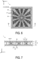
- FIGs. 6 and 7 illustrate the flow of the actuating fluid in the heat dissipation device 1 according to the embodiment.
- FIG. 6 is a view in which the third frame region 230 is omitted from the view illustrated in FIG. 5
- FIG. 7 is a cross-sectional view taken along arrow VII-VII in FIG. 6 .
- the vapor flow is indicated by white arrows
- the liquid flow is indicated by black arrows.
- the actuating fluid is vaporized into a vapor by being heated by a heat source.
- the heat source is disposed at the center portion of the upper surface (fifth surface) of the first member 10 (see FIGs. 1 and 2 ).
- the vapor of the actuating fluid is generated at the center portion of the first space (the space sandwiched between the first member 10 and the intermediate member 30).
- the vapor of the actuating fluid diffuses in the in-plane direction (XY plane direction) of the heat dissipation device 1 through the first groove portion 11 of the first groove forming region 110 (see white arrows in FIG. 6 ), while moving through the plurality of vapor holes 36 to the second space (space sandwiched between the second member 20 and intermediate member 30) (see white arrows in FIG. 7 ).
- the vapor that has moved to the second space condenses into a liquid as the temperature decreases.
- the liquefied actuating fluid moves through the second groove forming region 120 toward the center portion of the heat dissipation device 1 due to the capillary action of the second groove portion 21 (see black arrows in FIG. 6 ).
- the actuating fluid enters the reflux holes 37 and is returned to the first space by the capillary action of the reflux holes 37 (see the black arrows in FIG. 7 ).
- the heat dissipation device 1 can transfer heat from the heat source.
- FIG. 8 is a schematic cross-sectional view illustrating a configuration example of the communication path 14. Although the communication path 14 is illustrated in FIG. 8 as an example, the communication path 15 has the same or similar configuration as/to the communication path 14.
- the communication path 14 connects the internal space of the actuating region 100 with the outside.
- the communication path 14 includes a first portion 141 extending in the thickness direction (here, the Z-axis direction) of the container 2 and opening to the outside, and a second portion 142 extending in the surface direction (here, the Y-axis direction) of the container 2 and opening to the internal space of the actuating region 100.
- the first portion 141 is composed of a through hole 141a of the first member 10, a recessed portion 141b of the second member 20, and a through hole 141c of the intermediate member 30.
- the second portion 142 is composed of a groove portion 142b of the second member 20 and a lower surface 302 (second surface) of the intermediate member 30.
- FIG. 8 illustrates an example in which the recessed portion 141b of the communication path 14 is recessed deeper than the groove portion 142b of the second portion 142, but the recessed portion 141b and the groove portion 142b may be flush with each other.
- the communication path 14 includes the first portion 141 extending in the first direction (here, the Z-axis direction) and the second portion 142 extending in the direction (here, the Y-axis direction) intersecting the first direction.
- the communication path 14 is bent. Therefore, according to the heat dissipation device 1 of the embodiment, even when a high pressure is generated in the actuating region 100, the high pressure is unlikely to be applied to the sealing portion 5, thus increasing the reliability.
- a path width (a width along the Y-axis direction) of the first portion 141 is defined as D1
- a path width (a width along the Z-axis direction) of the second portion 142 is defined as D2.
- the path width D2 of the second portion 142 is less than the path width D 1 of the first portion 141.
- the cross-sectional area of the path of the second portion 142 is smaller than the cross-sectional area of the path of the first portion 141.
- Such a configuration can suppress the entry of the actuating fluid into the communication path 14 from the actuating region 100. This suppresses a decrease in the amount of the actuating fluid in the actuating region 100, thus restraining deterioration of the heat dissipation characteristic.
- a large cross-sectional area of the path of the first portion 141 facilitates injection of the actuating fluid during the manufacturing process of the heat dissipation device 1.
- the first portion 141 is open to the upper surface of the first member 10 and extends through the first and second spaces of the actuating region 100 in the frame region 200.
- the second portion 142 is located in the frame region 200 on the second space side of the actuating region 100.
- the first space side of the first space and the second space is under high pressure.
- the first space and the second space the second space side has a relatively low pressure.
- the second portion 142 located on the second space side can suppress application of a high pressure to the communication path 14.
- the communication path 14 is located so as to sandwich the actuating region 100 between the communication path 14 and the communication path 15.
- the two communication paths 14, 15 are arranged in this manner, a localized drop of durability can be suppressed, as compared to a case, for example, in which the two communication paths 14, 15 are arranged side by side.
- FIGs. 9 to 11 are schematic cross-sectional views illustrating configuration examples of the communication path 14.
- the sealing portion 5 is omitted for ease of understanding.
- the second portion 142 may have a protruding portion 41 that protrudes from the bottom surface of the groove portion 142b, that is, the upper surface (fourth surface) of the second member 20 toward the lower surface (second surface) of the intermediate member 30.
- the second portion 142 may have a protruding portion 42 that protrudes from the lower surface 302 (second surface) of the intermediate member 30 toward the bottom surface of the groove portion 142b.
- the path width D2 (see FIG. 8 ) of the second portion 142 is partially narrowed. This suppresses the entry of the actuating fluid located in the second space of the actuating region 100 into the communication path 14.
- the protruding portion 41 protruding from the bottom portion of the groove portion 142b side and the protruding portion 42 protruding from the lower surface (second surface) of the intermediate member 30 in the second portion 142 to form a labyrinth structure at the second portion 142 the entry of the actuating fluid into the communication path 14 can further be suppressed.
- FIG. 9 illustrates an example in which the protruding portion 41 is located at the end portion on the actuating region 100 side of both ends of the second portion 142, and the protruding portion 42 is located at the end portion on the first portion 141 side of both ends of the second portion 142.
- the protruding portion 41 may be located at the end portion of the first portion 141 side of both ends of the second portion 142
- the protruding portion 42 may be located at the end portion of the actuating region 100 side of both ends of the second portion 142.
- a stepped portion 43 extending radially outward of the first portion 141 may be provided at the opening end that opens to the outside.
- the stepped portion 43 expands the space in the communication path 14, relaxing the pressure applied to the communication path 14.
- the stepped portion 43 also increases the contact area with the sealing portion 5, thus enhancing the sealing characteristic of the actuating region 100.
- the stepped portion 43 facilitates the use of the helical insert, for example, as the sealing portion 5.
- Use of the helical insert as the sealing portion 5 facilitates connection of the heat dissipation device 1 with other members, for example.
- FIG. 12 is a schematic perspective view illustrating another configuration example of the second portion 142 of the communication path 14. Specifically, FIG. 12 is an enlarged view of a peripheral portion of the second portion 142 of the upper surface (fourth surface) of the second member 20.
- the cross-sectional area of each of the individual paths 142a to 142e is smaller than the cross-sectional area of the path of the first portion 141.
- a width of each of the individual path 142a to 142e is from 150 ⁇ m to 400 ⁇ m, and a height thereof is from 100 ⁇ m to 1,000 ⁇ m.
- the second portion 142 of the communication path 14 is divided into a plurality of individual paths 142a to 142e, each having a small cross-sectional area.
- Such a configuration further enhances the function of the capillary action compared to the case in which the second portion 142 includes one path. This allows smoother injection of the actuating fluid into the actuating region 100 in the manufacturing process of the heat dissipation device 1. This also makes it difficult to apply the high pressure of the actuating region 100 to the communication path 14 or the sealing portion 5 during the use of the heat dissipation device 1.
- Individual paths 142a to 142e extend linearly from the first portion 141 toward the actuating region 100.
- the second protrusions 21b of the second groove portion 21 are not located on the extension lines of the individual paths 142a to 142e.
- the individual paths 142a to 142e are each provided at a position that passes between two adjacent second protrusions 21b when the individual paths 142a to 142e extend toward the actuating region 100. Providing the individual paths 142a to 142e at such positions can make it difficult to obstruct the flow of the actuating fluid from the communication path 14 to the actuating region 100 by the second protrusions 21b.
- the individual paths 142a to 142e may approach each other from the first portion 141 toward the actuating region 100.
- the individual paths 142a to 142e may be separated from each other in a direction from the first portion 141 toward the actuating region 100.
- green sheets are formed by a doctor blade method or a roll compaction method using materials of the first member 10, the second member 20 and the intermediate member 30. Then, by layering a plurality of respective green sheets, a laminate body is obtained.
- the obtained laminate body is subjected to laser processing or die punching, thereby obtaining the respective compacts of the first member 10, the second member 20 and the intermediate member 30.
- a compact of the intermediate member 30 with through holes 141c, 151c, a plurality of vapor holes 36, and a plurality of reflux holes 37 can be obtained by applying laser processing to the laminate body.
- laser processing By applying laser processing to the resulting laminate body, a compact of the first member 10 in which the through holes 141a, 151a and the first groove forming region 110 are formed is obtained.
- a compact of the second member 20 with the recessed portions 141b, 151b, the groove portions 142b, 152b, and the second groove forming region 120 is obtained.
- the compacts of the first member 10, the second member 20, and the intermediate member 30 are respectively stacked and fired in the order of the second member 20, the intermediate member 30, and the first member 10 to obtain a sintered body of the container 2 in which the first member 10, the second member 20, and the intermediate member 30 are integrated.
- the first member 10, the second member 20 and the intermediate member 30 are integrally formed. Since no adhesive or the like is necessary, the highly reliable heat dissipation device 1 can be obtained.
- the method of obtaining the respective compacts of the first member 10, the second member 20, and the intermediate member 30 is not limited to the method described above.
- the green sheets may be processed and then laminated to obtain the compacts.
- the compact of the container 2 is obtained by fabricating the respective compacts of the first member 10, the second member 20, and the intermediate member 30 individually and then stacking them.
- the compact of the container 2 may be obtained by sequentially stacking processed green sheets, for example.
- the actuating fluid is injected into the sintered body from one of the communication paths 14, 15, for example.
- the gas present in the sintered body is discharged to the outside from the other of the communication paths 14, 15, in accordance with injection of the actuating fluid.
- the thermal device according to the embodiment can enhance the durability.
- the thermal device according to the present disclosure is not limited to the heat dissipation device.
- the thermal device according to the present disclosure may be a thermal storage device that stores latent heat associated with phase transformation of a thermal storage material (an example of the phase transformation substance) as thermal energy.
- a material that performs solid-liquid phase transformation or a material that performs solid-solid phase transformation is used as the heat storage material.
- the phase transformation substance is not necessarily required to undergo gas-liquid phase transformation.
- the phase transformation substance does not necessarily be liquid, but may be solid.
Landscapes
- Engineering & Computer Science (AREA)
- Physics & Mathematics (AREA)
- Thermal Sciences (AREA)
- Mechanical Engineering (AREA)
- General Engineering & Computer Science (AREA)
- Life Sciences & Earth Sciences (AREA)
- Sustainable Development (AREA)
- Microelectronics & Electronic Packaging (AREA)
- Ceramic Engineering (AREA)
- Cooling Or The Like Of Electrical Apparatus (AREA)
- Cooling Or The Like Of Semiconductors Or Solid State Devices (AREA)
Abstract
Description
- The present disclosure relates to a thermal device.
- A thermal device using latent heat of a phase transformation substance is known. For example, a vapor chamber, which is a kind of thermal device, utilizes latent heat associated with evaporation and condensation of an actuating fluid sealed inside and releases heat from a heat-generating component by transporting heat from a high-temperature portion to a low-temperature portion.
-
Patent Document 1 discloses a ceramic vapor chamber that includes an actuating region in which an actuating fluid is sealed, and a hole for injecting the actuating fluid into the actuating region is formed at a part of a ceramic plate-shaped body constituting the actuating region. - Patent Document 1:
JP54-42973 UM-A - A thermal device according to one aspect of the present disclosure is a thermal device that utilizes latent heat of a phase transformation substance, the thermal device including a ceramic container and a sealing portion. The container includes a phase transformation region in which a phase transformation substance is sealed, a frame region surrounding the phase transformation region, and a communication path configured to connect the phase transformation region with the outside. The sealing portion blocks the communication paths. The communication path is located in the frame region.
-
-
FIG. 1 is a perspective view of a heat dissipation device according to an embodiment. -
FIG. 2 is a view in which a first member according to an embodiment is viewed from a Z-axis negative direction side toward a Z-axis positive direction. -
FIG. 3 is a view in which a second member according to an embodiment is viewed from a Z-axis positive direction side toward a Z-axis negative direction. -
FIG. 4 is a view in which an intermediate member according to an embodiment is viewed from the Z-axis positive direction side toward the Z-axis negative direction. -
FIG. 5 is a view in which a first groove forming region illustrated inFIG. 2 and a second groove forming region illustrated inFIG. 3 are superimposed on the intermediate member illustrated inFIG. 4 . -
FIG. 6 is a view illustrating the flow of an actuating fluid in a heat dissipation device according to an embodiment. -
FIG. 7 is an explanatory view for explaining the flow of an actuating fluid in the heat dissipation device according to the embodiment. -
FIG. 8 is a schematic cross-sectional view illustrating a configuration example of a communication path. -
FIG. 9 is a schematic cross-sectional view illustrating another configuration example of the communication path. -
FIG. 10 is a schematic cross-sectional view illustrating another configuration example of the communication path. -
FIG. 11 is a schematic cross-sectional view illustrating another configuration example of the communication path. -
FIG. 12 is a schematic perspective view illustrating another configuration example of a second portion of the communication path. -
FIG. 13 is a schematic plan view illustrating another configuration example of individual paths. -
FIG. 14 is a schematic plan view illustrating another configuration example of the individual paths. -
FIG. 15 is a schematic plan view illustrating another configuration example of the individual paths. -
FIG. 16 is a schematic plan view illustrating another configuration example of the individual paths. - Modes (hereinafter will be referred to as "embodiments") for implementing a thermal device according to the present disclosure will be described below with reference to the accompanying drawings. The present disclosure is not limited by the embodiments. Embodiments can be appropriately combined so as not to contradict each other in terms of processing content. In the following embodiments, the same portions are denoted by the same reference signs, and overlapping explanations are omitted.
- In the embodiments described below, expressions such as "constant", "orthogonal", "perpendicular", and "parallel" may be used, but these expressions do not need to be exactly "constant", "orthogonal", "perpendicular", and "parallel". In other words, each of the above-described expressions allows for deviations in, for example, manufacturing accuracy, positioning accuracy, and the like.
- In each of the drawings referred to below, for ease of explanation, an X-axis direction, a Y-axis direction, and a Z-axis direction that are orthogonal to each other may be defined to illustrate a rectangular coordinate system in which the Z-axis positive direction is the vertically upward direction.
- In the following, a heat dissipation device, specifically a vapor chamber, which utilizes latent heat associated with evaporation and condensation of an actuating fluid (an example of the phase transformation substance) and efficiently transfers heat from a high-temperature part to a low-temperature part will be described as an example of a thermal device according to the present disclosure.
- An overall configuration of a heat dissipation device according to an embodiment is described with reference to
FIG. 1. FIG. 1 is a perspective view of a heat dissipation device according to an embodiment. - As illustrated in
FIG. 1 , theheat dissipation device 1 includes aceramic container 2. Thecontainer 2 has afirst member 10, asecond member 20, and anintermediate member 30. Thefirst member 10, thesecond member 20, and theintermediate member 30 are all plate-shaped, and are layered such that theintermediate member 30 is sandwiched between thefirst member 10 and thesecond member 20. - The
container 2 includes anactuating region 100 and aframe region 200. The actuatingregion 100 has an internal space in which an actuating fluid is sealed as a phase transformation substance. For example, water, a hydrocarbon-based compound, an organic liquid (for example, ethanol, methanol, or the like), or a liquid such as ammonium may be used as the actuating fluid. - The
frame region 200 is a region surrounding the actuatingregion 100. In other words, theframe region 200 is a region outside the actuatingregion 100 in theheat dissipation device 1. Theactuating region 100 is substantially hollow, while theframe region 200 is substantially solid. - The
frame region 200 is a region intentionally formed wide in order to suppress, for example, the leakage of the actuating fluid or the vapor of the actuating fluid from the interface between thefirst member 10 and theintermediate member 30 or between thesecond member 20 and theintermediate member 30. Theframe region 200 is also a region to suppress the entry of the external atmosphere into the internal space of the actuatingregion 100 through the interface (that is, to ensure the sealing characteristic). - The
container 2 has a plurality of (in this case, two)communication paths region 100 with the outside. For example, of thecommunication paths communication path 14 is used as an actuating fluid injection hole, while thecommunication path 15 is used as a gas discharge hole. In this case, in the manufacturing process of theheat dissipation device 1, the actuating fluid is injected into the internal space of the actuatingregion 100 through thecommunication path 14 and, accordingly, a gas present in the internal space of the actuatingregion 100 is discharged externally through thecommunication path 15. Thecommunication path 14 is located in the vicinity of one of four corners of thefirst member 10, and thecommunication path 15 is located in the vicinity of another corner located diagonally opposite thecommunication path 14. - The
heat dissipation device 1 does not necessarily have the plurality ofcommunication paths heat dissipation device 1 may be configured to include only one of thecommunication paths - The
communication paths portion 5. For the sealingportion 5, for example, a resin member, a metal member, a glass member, a ceramic member, or the like can be used. The sealingportion 5 may be flush with the upper surface of thefirst member 10 or may be raised from the upper surface of thefirst member 10. As will be described later, a helical insert may be used as a part of the sealingportion 5. When thecommunication paths portion 5, the internal space of theheat dissipation device 1 is sealed and the actuating fluid is enclosed in the actuatingregion 100. As described above, theheat dissipation device 1 is a sealed container with a sealed interior. - The actuating fluid fills the internal space of, for example, the
actuating region 100, at a ratio of from 10 vol% to 95 vol% with respect to the total volume of the internal space. Preferably, the ratio is from 30 vol% to 75 vol%. More preferably, the ratio is from 40 vol% to 65 vol%. The remaining portion of the internal space of theactuating region 100 other than the portion where the actuating fluid is present is in a vacuum state including some of the vaporized actuating fluid. This maintains vapor-liquid equilibrium in high-temperature environments, making it less prone to dry out, while allowing efficient thermal diffusion in low-temperature environments, thus achieving a high thermal diffusion characteristic in a wide temperature range. - The
first member 10, thesecond member 20, and theintermediate member 30 are made of a ceramic. Examples of the ceramic constituting thefirst member 10, thesecond member 20, and theintermediate member 30 that can be used include, for example, alumina (Al2O3), zirconia (ZrO2), silicon carbide (SiC), silicon nitride (Si3N4), aluminum nitride (AlN), cordierite (Mg2Al3(AlSi5O18)), and silicon impregnated silicon carbide (SiSiC). The ceramic constituting thefirst member 10, thesecond member 20, and theintermediate member 30 may be a single crystal. - A metal heat dissipation device is difficult to make thinner due to the difficulty in obtaining rigidity due to materials and manufacturing methods. Since the metal heat dissipation device includes a metal portion that contacts the actuating fluid, there is room for improvement in corrosion resistance. In contrast, since the
heat dissipation device 1 according to the embodiment is composed of thefirst member 10, thesecond member 20, and theintermediate member 30 which are all made of a ceramic, it is easier to make the device thinner and more corrosion-resistant than the heat dissipation device made of metal. - In the example illustrated in
FIG. 1 , theheat dissipation device 1 is placed with thefirst member 10 facing upward, but the installation state of theheat dissipation device 1 is not limited to the example illustrated inFIG. 1 . For example, theheat dissipation device 1 may be placed with thefirst member 10 facing downward. Theheat dissipation device 1 is not limited to the horizontal arrangement as illustrated inFIG. 1 , but may be arranged vertically. - Since ceramics are brittle, an important issue for the heat dissipation device including a ceramic container is how to ensure durability against a stress generated associated with, for example, phase transformation of the actuating fluid.
- Here, the vapor chamber described in
Patent Document 1 includes a communication path for injecting the actuating fluid in the actuating region. In the actuating region, the thickness of the ceramic is reduced by an amount corresponding to the internal space. Therefore, the chamber described inPatent Document 1 with the communication path provided in the actuating region easily lacks durability against stress and has a risk of generation of cracks or the like in the container. When the container is cracked, a dryout of the actuating fluid enclosed in the internal space may occur to deteriorate the heat dissipation efficiency. - In contrast, the
heat dissipation device 1 according to the embodiment includes thecommunication paths frame region 200. Unlike theactuating region 100, theframe region 200 is solid. Thecommunication paths frame region 200 can increase durability compared to the case in which thecommunication paths actuating region 100. Thus, theheat dissipation device 1 according to the embodiment can enhance durability. - The
heat dissipation device 1 according to the embodiment can also enhance the heat dissipation characteristic, because theactuating region 100 can have a wider effective space than the case in which thecommunication paths actuating region 100. - The
frame region 200 where thecommunication paths actuating region 100, making it less likely to generate stress due to a difference in thermal expansion. Thus, theheat dissipation device 1 according to the embodiment has a high reliability. - The configuration of the
first member 10 will be described with reference toFIG. 2. FIG. 2 is a view in which afirst member 10 according to an embodiment is viewed from the Z-axis negative direction side toward the Z-axis positive direction. -
FIG. 2 illustrates a lower surface of thefirst member 10, specifically, a surface (third surface) facing the upper surface (first surface) of theintermediate member 30. As illustrated inFIG. 2 , thefirst member 10 includes afirst groove portion 11 having a lattice shape on the third surface. - The
first groove portion 11 includes a first recessedportion 11a recessed with respect to the third surface and a plurality of first protrudingportions 11b located within the first recessedportion 11a. The first recessedportion 11a is located at the center portion of the third surface, and its contour in plan view is, for example, a square. The plurality of first protrudingportions 11b are arranged longitudinally and laterally at intervals from each other within the first recessedportion 11a. The first recessedportion 11a and the plurality of first protrudingportions 11b make thefirst groove portion 11 have a lattice shape. - Hereinafter, a region where the
first groove portion 11 is located on the third surface of thefirst member 10, will be referred to as a "firstgroove forming region 110". The firstgroove forming region 110 constitutes a part of theactuating region 100. Thefirst member 10 also includes afirst frame region 210 having a rectangular frame shape surrounding the firstgroove forming region 110. Thefirst frame region 210 constitutes a part of theframe region 200. - The
first frame region 210 has a plurality of (here, two) throughholes first member 10 in the thickness direction (here, the Z-axis direction). The throughhole 141a constitutes a part of afirst portion 141 of thecommunication path 14, and the throughhole 151a constitutes a part of afirst portion 151 of thecommunication path 15. - A heat source is disposed at the center portion of the upper surface (fifth surface) located opposite to the lower surface (third surface) of the
first member 10. - The configuration of the
second member 20 will be described with reference toFIG. 3. FIG. 3 is a view in which thesecond member 20 according to the embodiment is viewed from the Z-axis positive direction side toward the Z-axis negative direction. -
FIG. 3 illustrates the upper surface of thesecond member 20, specifically, the surface (the fourth surface) facing the lower surface (the second surface) of theintermediate member 30. As illustrated inFIG. 3 , thesecond member 20 includes asecond groove portion 21 having a lattice shape on the fourth surface. - The
second groove portion 21 includes a second recessedportion 21a recessed with respect to the fourth surface and a plurality of second protrudingportions 21b located within the second recessedportion 21a. The second recessedportion 21a is located at the center portion of the fourth surface, and its contour in plan view is, for example, a square. The plurality of second protrudingportions 21b are arranged longitudinally and laterally at intervals from each other within the second recessedportion 21a. The second recessedportion 21a and the plurality of second protrudingportions 21b make thesecond groove portion 21 have a lattice shape. - Hereinafter, a region where the
second groove portion 21 is located on the fourth surface of thesecond member 20 will be referred to as a "secondgroove forming region 120". The secondgroove forming region 120 constitutes a part of theactuating region 100. Thesecond member 20 includes asecond frame region 220 having a rectangular frame shape surrounding the secondgroove forming region 120. Thesecond frame region 220 constitutes a part of theframe region 200. - The size of the second
groove forming region 120 in thesecond member 20 is the same as the size of the firstgroove forming region 110 in thefirst member 10. The position of the secondgroove forming region 120 on the fourth surface of thesecond member 20 is the same as the position of the firstgroove forming region 110 on the third surface of thefirst member 10. - Thus, by forming the first and
second groove portions heat dissipation device 1. Note that each of thefirst groove portion 11 and thesecond groove portion 21 need not necessarily have a lattice shape. - Located in the
second frame region 220 are a plurality of (here, two) recessedportions second member 20. The recessedportion 141b constitutes a part of thefirst portion 141 in thecommunication path 14, and the recessedportion 151b constitutes a part of thefirst portion 151 in thecommunication path 15. - The
second frame region 220 also includesgroove portions groove portion 142b is a path extending in a second direction (here, the Y-axis direction) intersecting the extending direction (which is the first direction, and here, the Z-axis direction) of thefirst portion 141 in thecommunication path 14. One end of thegroove portion 142b is open to the recessedportion 141b at thefirst portion 141, and the other end is open to the secondgroove forming region 120. Thegroove portion 152b is a path extending in a second direction (here, the Y-axis direction) intersecting the extending direction (which is the first direction, and here, the Z-axis direction) of thefirst portion 151 in thecommunication path 15. One end of thegroove 152b is open to the recessedportion 151b at thefirst portion 151, and the other end is open to the secondgroove forming region 120. - The configuration of the
intermediate member 30 will be described with reference toFIG. 4. FIG. 4 is a view in which anintermediate member 30 according to the embodiment is viewed from the Z-axis positive direction side toward the Z-axis negative direction. - As illustrated in
FIG. 4 , theintermediate member 30 has athird frame region 230 having a rectangular frame shape. Thethird frame region 230 constitutes a part of theframe region 200. Theintermediate member 30 includes acircular center portion 32 in a plan view located inside thethird frame region 230 and a plurality ofconnections 33 located between thecenter portion 32 and thethird frame region 230 and connecting thecenter portion 32 and thethird frame region 230. In the example illustrated inFIG. 4 , thecenter portion 32 is located at the center ofintermediate member 30. The plurality ofconnections 33 are spaced apart from each other and extends radially while widening from thecenter portion 32 toward thethird frame region 230. - The
intermediate member 30 also includes a plurality of vapor holes 36 and a plurality of reflux holes 37. Each of the plurality of vapor holes 36 and each of the plurality of reflux holes 37 extend through the upper surface (first surface) and the lower surface (second surface) of theintermediate member 30. - The plurality of vapor holes 36 function as a part of a path for the vapor of the actuating fluid. Each of the plurality of vapor holes 36 is located between two
adjacent connections 33. That is, the plurality of vapor holes 36 and the plurality ofconnections 33 are alternately located in the circumferential direction. Being the same as and/or similar to the plurality ofconnections 33, the plurality of vapor holes 36 are spaced apart from each other and extends radially while widening from thecenter portion 32 toward thethird frame region 230. - The plurality of reflux holes 37 function as a part of a path for the actuating fluid. The reflux holes 37 are micropores, each having an opening area smaller than the vapor holes 36 described above. Specifically, the reflux holes 37 are small enough to allow capillary phenomenon to occur in the actuating fluid passing through the reflux holes 37.
- In the
third frame region 230, a plurality (here, two) of throughholes intermediate member 30 in the thickness direction (here, in the Z-axis direction). The throughhole 141c constitutes a part of thefirst portion 141 of thecommunication path 14, and the throughhole 151c constitutes a part of thefirst portion 151 of thecommunication path 15. -
FIG. 5 is a view in which the firstgroove forming region 110 illustrated inFIG. 2 and the secondgroove forming region 120 illustrated inFIG. 3 are superimposed on theintermediate member 30 illustrated inFIG. 4 . InFIG. 5 , thecommunication paths - As illustrated in
FIG. 5 , the first and secondgroove forming regions third frame region 230 of theintermediate member 30. That is, the first and secondgroove forming regions intermediate member 30. - Thus, by making the first
groove forming region 110 of thefirst member 10 and the secondgroove forming region 120 of thesecond member 20 wider than the hole forming region of theintermediate member 30, the internal space of theheat dissipation device 1 can be expanded outward compared to a case in which the first and secondgroove forming regions - The heat source is disposed at the center portion of the
heat dissipation device 1. The temperature of theheat dissipation device 1 becomes lower as it is away from the heat source, that is, as it becomes closer to the outer peripheral portion of theheat dissipation device 1. The vapor of the actuating fluid condenses into a liquid upon moving to a low-temperature region. By spreading the internal space of theheat dissipation device 1 outward, condensation of the actuating fluid is more likely to occur. This makes it difficult for dryout to occur. - Here, an example in which the first
groove forming region 110 and the secondgroove forming region 120 spread outward from the hole forming region of theintermediate member 30 is illustrated; however, the configuration is not limited to this, the hole forming region of theintermediate member 30 may spread outward from the firstgroove forming region 110 and the secondgroove forming region 120. - The
actuating region 100 of theheat dissipation device 1 has an internal space sandwiched between the firstgroove forming region 110 and the secondgroove forming region 120, and an actuating fluid is enclosed in the internal space. Theintermediate member 30 is interposed between the first and secondgroove forming regions actuating region 100 is partitioned into a first space sandwiched between the firstgroove forming region 110 and theintermediate member 30 and a second space sandwiched between the secondgroove forming region 120 and theintermediate member 30. The first space and the second space are connected via the vapor holes 36 and the reflux holes 37 formed in theintermediate member 30. - The flow of the actuating fluid in the
heat dissipation device 1 according to the embodiment is described with reference toFIGs. 6 and 7. FIGs. 6 and 7 illustrate the flow of the actuating fluid in theheat dissipation device 1 according to the embodiment.FIG. 6 is a view in which thethird frame region 230 is omitted from the view illustrated inFIG. 5 , andFIG. 7 is a cross-sectional view taken along arrow VII-VII inFIG. 6 . InFIGs. 6 and 7 , the vapor flow is indicated by white arrows, and the liquid flow is indicated by black arrows. - The actuating fluid is vaporized into a vapor by being heated by a heat source. As described above, the heat source is disposed at the center portion of the upper surface (fifth surface) of the first member 10 (see
FIGs. 1 and 2 ). Thus, the vapor of the actuating fluid is generated at the center portion of the first space (the space sandwiched between thefirst member 10 and the intermediate member 30). - The vapor of the actuating fluid diffuses in the in-plane direction (XY plane direction) of the
heat dissipation device 1 through thefirst groove portion 11 of the first groove forming region 110 (see white arrows inFIG. 6 ), while moving through the plurality ofvapor holes 36 to the second space (space sandwiched between thesecond member 20 and intermediate member 30) (see white arrows inFIG. 7 ). - The vapor that has moved to the second space condenses into a liquid as the temperature decreases. The liquefied actuating fluid moves through the second
groove forming region 120 toward the center portion of theheat dissipation device 1 due to the capillary action of the second groove portion 21 (see black arrows inFIG. 6 ). In this process, the actuating fluid enters the reflux holes 37 and is returned to the first space by the capillary action of the reflux holes 37 (see the black arrows inFIG. 7 ). By repeating the above cycle, theheat dissipation device 1 can transfer heat from the heat source. - The configuration of the
communication paths FIG. 8. FIG. 8 is a schematic cross-sectional view illustrating a configuration example of thecommunication path 14. Although thecommunication path 14 is illustrated inFIG. 8 as an example, thecommunication path 15 has the same or similar configuration as/to thecommunication path 14. - As illustrated in
FIG. 8 , thecommunication path 14 connects the internal space of theactuating region 100 with the outside. Thecommunication path 14 includes afirst portion 141 extending in the thickness direction (here, the Z-axis direction) of thecontainer 2 and opening to the outside, and asecond portion 142 extending in the surface direction (here, the Y-axis direction) of thecontainer 2 and opening to the internal space of theactuating region 100. - The
first portion 141 is composed of a throughhole 141a of thefirst member 10, a recessedportion 141b of thesecond member 20, and a throughhole 141c of theintermediate member 30. Thesecond portion 142 is composed of agroove portion 142b of thesecond member 20 and a lower surface 302 (second surface) of theintermediate member 30.FIG. 8 illustrates an example in which the recessedportion 141b of thecommunication path 14 is recessed deeper than thegroove portion 142b of thesecond portion 142, but the recessedportion 141b and thegroove portion 142b may be flush with each other. - Thus, the
communication path 14 includes thefirst portion 141 extending in the first direction (here, the Z-axis direction) and thesecond portion 142 extending in the direction (here, the Y-axis direction) intersecting the first direction. In other words, thecommunication path 14 is bent. Therefore, according to theheat dissipation device 1 of the embodiment, even when a high pressure is generated in theactuating region 100, the high pressure is unlikely to be applied to the sealingportion 5, thus increasing the reliability. - In a cross-sectional view (that is, a cross-sectional view illustrated in
FIG. 8 ) of thecommunication path 14 when cut along the thickness direction (here, the Z-axis direction) of thecontainer 2, a path width (a width along the Y-axis direction) of thefirst portion 141 is defined as D1, and a path width (a width along the Z-axis direction) of thesecond portion 142 is defined as D2. In this case, the path width D2 of thesecond portion 142 is less than thepath width D 1 of thefirst portion 141. In other words, the cross-sectional area of the path of thesecond portion 142 is smaller than the cross-sectional area of the path of thefirst portion 141. - Such a configuration can suppress the entry of the actuating fluid into the
communication path 14 from theactuating region 100. This suppresses a decrease in the amount of the actuating fluid in theactuating region 100, thus restraining deterioration of the heat dissipation characteristic. A large cross-sectional area of the path of thefirst portion 141 facilitates injection of the actuating fluid during the manufacturing process of theheat dissipation device 1. - The
first portion 141 is open to the upper surface of thefirst member 10 and extends through the first and second spaces of theactuating region 100 in theframe region 200. Thesecond portion 142 is located in theframe region 200 on the second space side of theactuating region 100. - In the
heat dissipation device 1, the first space side of the first space and the second space is under high pressure. In other words, the first space and the second space, the second space side has a relatively low pressure. Thesecond portion 142 located on the second space side can suppress application of a high pressure to thecommunication path 14. - As illustrated in
FIG. 1 , thecommunication path 14 is located so as to sandwich theactuating region 100 between thecommunication path 14 and thecommunication path 15. By arranging the twocommunication paths communication paths -
FIGs. 9 to 11 are schematic cross-sectional views illustrating configuration examples of thecommunication path 14. InFIG. 11 , the sealingportion 5 is omitted for ease of understanding. - As illustrated in
FIG. 9 , thesecond portion 142 may have a protrudingportion 41 that protrudes from the bottom surface of thegroove portion 142b, that is, the upper surface (fourth surface) of thesecond member 20 toward the lower surface (second surface) of theintermediate member 30. Thesecond portion 142 may have a protrudingportion 42 that protrudes from the lower surface 302 (second surface) of theintermediate member 30 toward the bottom surface of thegroove portion 142b. - Thus, when the protruding
portions second portion 142, the path width D2 (seeFIG. 8 ) of thesecond portion 142 is partially narrowed. This suppresses the entry of the actuating fluid located in the second space of theactuating region 100 into thecommunication path 14. By providing the protrudingportion 41 protruding from the bottom portion of thegroove portion 142b side and the protrudingportion 42 protruding from the lower surface (second surface) of theintermediate member 30 in thesecond portion 142 to form a labyrinth structure at thesecond portion 142, the entry of the actuating fluid into thecommunication path 14 can further be suppressed. -
FIG. 9 illustrates an example in which the protrudingportion 41 is located at the end portion on theactuating region 100 side of both ends of thesecond portion 142, and the protrudingportion 42 is located at the end portion on thefirst portion 141 side of both ends of thesecond portion 142. Alternatively, the protrudingportion 41 may be located at the end portion of thefirst portion 141 side of both ends of thesecond portion 142, and the protrudingportion 42 may be located at the end portion of theactuating region 100 side of both ends of thesecond portion 142. - As illustrated in
FIG. 10 , thefirst portion 141 may be tapered with the width of the path gradually narrowing in a direction from the opening portion, which opens to the outside, toward the depth of thecontainer 2. In other words, thefirst portion 141 may have a larger cross-sectional area of the path at the connecting end connected to thesecond portion 142 than a cross-sectional area of the path at the opening end that opens to the outside. In this way, by narrowing thefirst portion 141 on thesecond portion 142 side, the entry of the actuating fluid into thecommunication path 14 from theactuating region 100 can further be suppressed. Even when the actuating fluid enters thecommunication path 14, the actuating fluid that has entered thecommunication path 14 can be returned more easily to theactuating region 100 due to the capillary action by narrowing thefirst portion 141. - As illustrated in
FIG. 11 , a steppedportion 43 extending radially outward of thefirst portion 141 may be provided at the opening end that opens to the outside. The steppedportion 43 expands the space in thecommunication path 14, relaxing the pressure applied to thecommunication path 14. The steppedportion 43 also increases the contact area with the sealingportion 5, thus enhancing the sealing characteristic of theactuating region 100. The steppedportion 43 facilitates the use of the helical insert, for example, as the sealingportion 5. Use of the helical insert as the sealingportion 5 facilitates connection of theheat dissipation device 1 with other members, for example. -
FIG. 12 is a schematic perspective view illustrating another configuration example of thesecond portion 142 of thecommunication path 14. Specifically,FIG. 12 is an enlarged view of a peripheral portion of thesecond portion 142 of the upper surface (fourth surface) of thesecond member 20. - As illustrated in
FIG. 12 , thesecond portion 142 has a plurality of (here, five)individual paths 142a to 142e. The plurality ofindividual paths 142a to 142e individually connect thefirst portion 141 to theactuating region 100. That is, each of theindividual paths 142a to 142e opens to therecess 141b of thefirst portion 141 at one end, while opening to the secondgroove forming region 120 at the other end. - The cross-sectional area of each of the
individual paths 142a to 142e is smaller than the cross-sectional area of the path of thefirst portion 141. In an example, a width of each of theindividual path 142a to 142e is from 150 µm to 400 µm, and a height thereof is from 100 µm to 1,000 µm. - Thus, the
second portion 142 of thecommunication path 14 is divided into a plurality ofindividual paths 142a to 142e, each having a small cross-sectional area. Such a configuration further enhances the function of the capillary action compared to the case in which thesecond portion 142 includes one path. This allows smoother injection of the actuating fluid into theactuating region 100 in the manufacturing process of theheat dissipation device 1. This also makes it difficult to apply the high pressure of theactuating region 100 to thecommunication path 14 or the sealingportion 5 during the use of theheat dissipation device 1. -
Individual paths 142a to 142e extend linearly from thefirst portion 141 toward theactuating region 100. In this case, thesecond protrusions 21b of thesecond groove portion 21 are not located on the extension lines of theindividual paths 142a to 142e. In other words, theindividual paths 142a to 142e are each provided at a position that passes between two adjacentsecond protrusions 21b when theindividual paths 142a to 142e extend toward theactuating region 100. Providing theindividual paths 142a to 142e at such positions can make it difficult to obstruct the flow of the actuating fluid from thecommunication path 14 to theactuating region 100 by thesecond protrusions 21b. - Note that
FIG. 13 illustrates an example in which thesecond protrusions 21b are not located on all extension lines of theindividual paths 142a to 142e, but thesecond protrusions 21b may not be located on the extension line of at least one of theindividual paths 142a to 142e. -
FIGs. 13 to 16 are schematic plan views illustrating other configuration examples of theindividual paths 142a to 142e. - As illustrated in
FIG. 13 , theindividual paths 142a to 142e may extend in the second direction (the Y-direction) in a meandering manner in the plane (the XY plane) of the upper surface (second surface) of thesecond member 20. Such a configuration can increase the resistance of the flow path in theindividual paths 142a to 142e. This further suppresses the entry of the actuating fluid in theactuating region 100 into thecommunication path 14. - As illustrated in
FIG. 14 , theindividual paths 142a to 142e may approach each other from thefirst portion 141 toward theactuating region 100. Alternatively, as illustrated inFIG. 15 , theindividual paths 142a to 142e may be separated from each other in a direction from thefirst portion 141 toward theactuating region 100. - As described above, the plurality of
individual paths 142a to 142e do not necessarily need to extend in the same direction. The extending directions of the plurality ofindividual paths 142a to 142e may differ from each other, and thus it makes it possible, for example, to obtain thecommunication path 14 in which the flow direction of the actuating fluid flowing into theactuating region 100 from theindividual paths 142a to 142e is adjusted not to hit thesecond protrusions 21b located in theactuating region 100 as much as possible. - As illustrated in
FIG. 16 , each of theindividual paths 142a to 142e may be tapered with a cross-sectional area decreasing from thefirst portion 141 toward theactuating region 100. Such a configuration facilitates the entry of the actuating fluid into theactuating region 100 from thefirst portion 141 due to the capillary action that gradually increases from thefirst portion 141 toward theactuating region 100. In other words, the entry of the actuating fluid into thecommunication path 14 from theactuating region 100 can further be suppressed. - An example of a method for manufacturing the
heat dissipation device 1 according to the embodiment is described. First, green sheets are formed by a doctor blade method or a roll compaction method using materials of thefirst member 10, thesecond member 20 and theintermediate member 30. Then, by layering a plurality of respective green sheets, a laminate body is obtained. - Subsequently, the obtained laminate body is subjected to laser processing or die punching, thereby obtaining the respective compacts of the
first member 10, thesecond member 20 and theintermediate member 30. For example, a compact of theintermediate member 30 with throughholes first member 10 in which the throughholes groove forming region 110 are formed is obtained. By applying laser processing to the resulting laminate body, a compact of thesecond member 20 with the recessedportions groove portions groove forming region 120 is obtained. - Subsequently, the compacts of the
first member 10, thesecond member 20, and theintermediate member 30 are respectively stacked and fired in the order of thesecond member 20, theintermediate member 30, and thefirst member 10 to obtain a sintered body of thecontainer 2 in which thefirst member 10, thesecond member 20, and theintermediate member 30 are integrated. In this way, thefirst member 10, thesecond member 20 and theintermediate member 30 are integrally formed. Since no adhesive or the like is necessary, the highly reliableheat dissipation device 1 can be obtained. - The method of obtaining the respective compacts of the
first member 10, thesecond member 20, and theintermediate member 30 is not limited to the method described above. For example, the green sheets may be processed and then laminated to obtain the compacts. In the above example, the compact of thecontainer 2 is obtained by fabricating the respective compacts of thefirst member 10, thesecond member 20, and theintermediate member 30 individually and then stacking them. Alternatively, the compact of thecontainer 2 may be obtained by sequentially stacking processed green sheets, for example. - Subsequently, the actuating fluid is injected into the sintered body from one of the
communication paths communication paths - Subsequently, a vacuum pump or other pressure reducing device is used to evacuate the inside of the sintered body through the
communication paths communication paths communication paths portion 5, and theheat dissipation device 1 is obtained. - As described above, the thermal device (for example, the heat dissipation device 1) according to the embodiment is a thermal device that utilizes the latent heat of a phase transformation substance (for example, the actuating fluid), and the thermal device includes a ceramic container (for example, the container 2) and a sealing portion (for example, the sealing portion 5). The container includes a phase transformation region (for example, the actuating region 100) in which a phase transformation substance is sealed, a frame region (for example, the frame region 200) surrounding the phase transformation region, and communication paths (for example, the
communication paths 14, 15) configured to connect the phase transformation region with the outside. The sealing portion blocks the communication paths. The communication paths are located in the frame region. - Thus, the thermal device according to the embodiment can enhance the durability.
- The thermal device according to the present disclosure is not limited to the heat dissipation device. For example, the thermal device according to the present disclosure may be a thermal storage device that stores latent heat associated with phase transformation of a thermal storage material (an example of the phase transformation substance) as thermal energy. In that case, a material that performs solid-liquid phase transformation or a material that performs solid-solid phase transformation is used as the heat storage material. Thus, the phase transformation substance is not necessarily required to undergo gas-liquid phase transformation. In other words, the phase transformation substance does not necessarily be liquid, but may be solid.
- Note that the embodiments disclosed herein are exemplary in all respects and not restrictive. The aforementioned embodiments can be embodied in a variety of forms. The above-described embodiments may be omitted, substituted or modified in various forms without departing from the scope and spirit of the appended claims.
-
- 1 Heat dissipation device
- 5 Sealing portion
- 10 First member
- 11 First groove portion
- 11a First recessed portion
- 11b First protruding portion
- 14,15 Communication path
- 20 Second member
- 21 Second groove portion
- 21a Second recessed portion
- 21b Second protruding portion
- 30 Intermediate member
- 36 Vapor hole
- 37 Reflux hole
- 100 Actuating region
- 141 First portion
- 141a Through hole
- 141b Recessed portion
- 141c Through hole
- 142 Second portion
- 142a Individual path
- 200 Frame region
Claims (14)
- A thermal device that utilizes latent heat of a phase transformation substance, comprising:a ceramic container comprising a phase transformation region in which the phase transformation substance is sealed, a frame region surrounding the phase transformation region, and a communication path configured to connect the phase transformation region with the outside; anda sealing portion configured to block the communication path, whereinthe communication path is located in the frame region.
- The thermal device according to claim 1, wherein
the communication path comprisesa first portion extending in a first direction and opening to the outside, anda second portion extending in a second direction intersecting the first direction and opening to the phase transformation region. - The thermal device according to claim 2, wherein
a cross-sectional area of a path at the second portion is smaller than a cross-sectional area of a path at the first portion. - The thermal device according to claim 2, wherein
the second portion comprises a plurality of individual paths each having a cross-sectional area smaller than a cross-sectional area of a path at the first portion. - The thermal device according to claim 4, wherein
the plurality of individual paths extend in the second direction in a meandering manner. - The thermal device according to claim 4 or 5, wherein
the plurality of individual paths approach each other further from the first portion toward the phase transformation region. - The thermal device according to claim 4 or 5, wherein
the plurality of individual paths are separated from each other further from the first portion toward the phase transformation region. - The thermal device according to any one of claims 4 to 7, wherein
the individual paths each have a cross-sectional area that is smaller from the first portion toward the phase transformation region. - The thermal device according to any one of claims 2 to 8, whereinthe container comprisesan intermediate member having a plate shape and comprising a plurality of reflux holes extending through a first surface and a second surface located on an opposite side of the first surface,a first member comprising a first groove portion on a third surface facing the first surface of the intermediate member, and comprising a heat source disposed on a fifth surface opposite to the third surface, anda second member comprising a second groove portion on a fourth surface facing the second surface of the intermediate member, whereinan actuating fluid is located as the phase transformation substance in the phase transformation region sandwiched between the first groove portion and the second groove portion.
- The thermal device according to claim 9, whereinthe phase transformation region comprisesa first space sandwiched between the first surface of the intermediate member and the third surface of the first member, anda second space sandwiched between the second surface of the intermediate member and the fourth surface of the second member,the first portion extends across the first space and the second space in the frame region in a cross-sectional view of the container, andthe second portion is located on the second space side of the first space and the second space in the frame region in the cross-sectional view of the container.
- The thermal device according to claim 10, wherein
the second portion comprises a protruding portion protruding from a surface facing the second surface toward the second surface. - The thermal device according to any one of claims 8 to 11, wherein
the first portion has a larger cross-sectional area of the path at a connecting end connected to the second portion than a cross-sectional area of the path at an opening end that opens to the outside. - The thermal device according to any one of claims 8 to 12, wherein
the first portion comprises a stepped portion at the opening end that opens to the outside. - The thermal device according to any one of claims 8 to 13, comprising:at least two of the communication paths, whereinone of the communication paths is located with the phase transformation region sandwiched between the one of the communication paths and the other communication path.
Applications Claiming Priority (2)
| Application Number | Priority Date | Filing Date | Title |
|---|---|---|---|
| JP2021030210 | 2021-02-26 | ||
| PCT/JP2022/006476 WO2022181453A1 (en) | 2021-02-26 | 2022-02-17 | Thermal device |
Publications (2)
| Publication Number | Publication Date |
|---|---|
| EP4300572A1 true EP4300572A1 (en) | 2024-01-03 |
| EP4300572A4 EP4300572A4 (en) | 2025-01-15 |
Family
ID=83048925
Family Applications (1)
| Application Number | Title | Priority Date | Filing Date |
|---|---|---|---|
| EP22759489.2A Pending EP4300572A4 (en) | 2021-02-26 | 2022-02-17 | THERMAL DEVICE |
Country Status (6)
| Country | Link |
|---|---|
| US (1) | US12595974B2 (en) |
| EP (1) | EP4300572A4 (en) |
| JP (1) | JP7635359B2 (en) |
| KR (1) | KR20230136170A (en) |
| CN (1) | CN116940796A (en) |
| WO (1) | WO2022181453A1 (en) |
Families Citing this family (1)
| Publication number | Priority date | Publication date | Assignee | Title |
|---|---|---|---|---|
| CN114608368A (en) * | 2020-12-08 | 2022-06-10 | 绍兴三花新能源汽车部件有限公司 | Heat exchanger |
Family Cites Families (23)
| Publication number | Priority date | Publication date | Assignee | Title |
|---|---|---|---|---|
| US2782010A (en) * | 1948-12-18 | 1957-02-19 | Modine Mfg Co | Heat exchanger |
| GB1467182A (en) | 1973-12-26 | 1977-03-16 | Burroughs Corp | Gas discharge display panel |
| JPS5732613Y2 (en) | 1976-12-31 | 1982-07-17 | ||
| JPS5918631B2 (en) | 1977-02-28 | 1984-04-28 | 日本特殊陶業株式会社 | Manufacturing method of ceramic heat pipe |
| JPS5810370Y2 (en) | 1977-08-26 | 1983-02-25 | 日本特殊陶業株式会社 | Ceramic substrate for mounting electronic circuit equipment |
| JP2539663B2 (en) | 1988-05-11 | 1996-10-02 | 株式会社フジクラ | High temperature ceramic heat pipe |
| US20020192531A1 (en) * | 1998-12-30 | 2002-12-19 | Joerg Zimmerman | Liquid reactant flow field plates for liquid feed fuel cells |
| JP2002081874A (en) | 2000-09-11 | 2002-03-22 | Canon Inc | Plate type heat pipe and manufacturing method thereof |
| US7414843B2 (en) * | 2004-03-10 | 2008-08-19 | Intel Corporation | Method and apparatus for a layered thermal management arrangement |
| WO2007029359A1 (en) * | 2005-09-01 | 2007-03-15 | Fuchigami Micro Co., Ltd. | Heat pipe and method for manufacturing same |
| JP4035155B1 (en) * | 2006-07-28 | 2008-01-16 | 株式会社渕上ミクロ | Heat pipe and manufacturing method thereof |
| JP2009024933A (en) * | 2007-07-19 | 2009-02-05 | Sony Corp | Thermal diffusion device and manufacturing method thereof |
| US20090178784A1 (en) * | 2008-01-15 | 2009-07-16 | Chin-Wen Wang | Manufacturing Method of Isothermal Vapor Chamber And Product Thereof |
| JP4683080B2 (en) | 2008-07-10 | 2011-05-11 | ソニー株式会社 | HEAT TRANSPORT DEVICE, ELECTRONIC APPARATUS, ENCLOSURE APPARATUS AND METHOD |
| JP2010243077A (en) * | 2009-04-07 | 2010-10-28 | Sony Corp | Heat transport device manufacturing method, heat transport device, electronic apparatus, and caulking pin |
| KR101205715B1 (en) * | 2010-05-24 | 2012-11-28 | 한국과학기술원 | Heat spreader with flat plate and manufacturing method thereof |
| JP2012132582A (en) | 2010-12-20 | 2012-07-12 | Furukawa Electric Co Ltd:The | Thin sheet type heat pipe |
| US20180156545A1 (en) * | 2016-12-05 | 2018-06-07 | Microsoft Technology Licensing, Llc | Vapor chamber with three-dimensional printed spanning structure |
| CN211668321U (en) | 2017-01-27 | 2020-10-13 | 古河电气工业株式会社 | Vapor chamber |
| TWI794886B (en) * | 2017-02-24 | 2023-03-01 | 日商大日本印刷股份有限公司 | Steam chamber, electronic device and manufacturing method of steam chamber |
| TWI658248B (en) * | 2018-02-13 | 2019-05-01 | 奇鋐科技股份有限公司 | Vapor chamber water-filling section sealing structure and manufacturing method thereof |
| CN112902717B (en) | 2018-05-30 | 2022-03-11 | 大日本印刷株式会社 | Plates for evaporation chambers, evaporation chambers and electronics |
| US20240255939A1 (en) | 2023-01-27 | 2024-08-01 | Hitachi, Ltd. | Reinforcement learning system for maintenance decision making |
-
2022
- 2022-02-17 WO PCT/JP2022/006476 patent/WO2022181453A1/en not_active Ceased
- 2022-02-17 CN CN202280016718.2A patent/CN116940796A/en active Pending
- 2022-02-17 JP JP2023502338A patent/JP7635359B2/en active Active
- 2022-02-17 KR KR1020237028742A patent/KR20230136170A/en active Pending
- 2022-02-17 US US18/279,010 patent/US12595974B2/en active Active
- 2022-02-17 EP EP22759489.2A patent/EP4300572A4/en active Pending
Also Published As
| Publication number | Publication date |
|---|---|
| EP4300572A4 (en) | 2025-01-15 |
| US12595974B2 (en) | 2026-04-07 |
| US20240142179A1 (en) | 2024-05-02 |
| CN116940796A (en) | 2023-10-24 |
| JP7635359B2 (en) | 2025-02-25 |
| JPWO2022181453A1 (en) | 2022-09-01 |
| KR20230136170A (en) | 2023-09-26 |
| WO2022181453A1 (en) | 2022-09-01 |
Similar Documents
| Publication | Publication Date | Title |
|---|---|---|
| CN115136302B (en) | Heat radiation member | |
| TWI812723B (en) | Vapor chamber, electronic device and sheet for vapor chamber | |
| US10420253B2 (en) | Loop heat pipe, manufacturing method thereof, and electronic device | |
| US20200355444A1 (en) | Vapor chamber and manufacturing method of the same | |
| JP7791301B2 (en) | Thermal Devices | |
| US11774181B2 (en) | Loop heat pipe with recessed top or bottom surface | |
| EP4300572A1 (en) | Thermal device | |
| EP4300573A1 (en) | Thermal device | |
| EP3477236A1 (en) | Heat pipe and method for manufacturing heat pipe | |
| EP4446684A1 (en) | Vapor chamber device | |
| CN107801358A (en) | Straight-through structure of heat dissipation unit | |
| US20250354759A1 (en) | Thermal device | |
| WO2026048992A1 (en) | Thermal device | |
| WO2025197761A1 (en) | Thermal device | |
| KR100698460B1 (en) | Plate Cooling Units and Chipsets Using the Same | |
| CN207491438U (en) | Straight-through structure of cooling unit | |
| JP7743889B2 (en) | Vapor chambers and electronic devices | |
| KR102368500B1 (en) | Flat Plate Type Heat Dissipation Device that Could be Separated to Cool Several Heat Sources Simultaneously | |
| KR20060054251A (en) | Plate Cooling Apparatus and Manufacturing Method Thereof | |
| WO2022025254A1 (en) | Heat conduction member |
Legal Events
| Date | Code | Title | Description |
|---|---|---|---|
| STAA | Information on the status of an ep patent application or granted ep patent |
Free format text: STATUS: THE INTERNATIONAL PUBLICATION HAS BEEN MADE |
|
| PUAI | Public reference made under article 153(3) epc to a published international application that has entered the european phase |
Free format text: ORIGINAL CODE: 0009012 |
|
| STAA | Information on the status of an ep patent application or granted ep patent |
Free format text: STATUS: REQUEST FOR EXAMINATION WAS MADE |
|
| 17P | Request for examination filed |
Effective date: 20230824 |
|
| AK | Designated contracting states |
Kind code of ref document: A1 Designated state(s): AL AT BE BG CH CY CZ DE DK EE ES FI FR GB GR HR HU IE IS IT LI LT LU LV MC MK MT NL NO PL PT RO RS SE SI SK SM TR |
|
| DAV | Request for validation of the european patent (deleted) | ||
| DAX | Request for extension of the european patent (deleted) | ||
| REG | Reference to a national code |
Ref country code: DE Ref legal event code: R079 Free format text: PREVIOUS MAIN CLASS: H01L0023427000 Ipc: F28D0015020000 |
|
| A4 | Supplementary search report drawn up and despatched |
Effective date: 20241213 |
|
| RIC1 | Information provided on ipc code assigned before grant |
Ipc: F28F 3/08 20060101ALI20241209BHEP Ipc: F28D 15/04 20060101ALI20241209BHEP Ipc: H01L 23/427 20060101ALI20241209BHEP Ipc: F28D 15/02 20060101AFI20241209BHEP |
|
| GRAP | Despatch of communication of intention to grant a patent |
Free format text: ORIGINAL CODE: EPIDOSNIGR1 |
|
| STAA | Information on the status of an ep patent application or granted ep patent |
Free format text: STATUS: GRANT OF PATENT IS INTENDED |
|
| RIC1 | Information provided on ipc code assigned before grant |
Ipc: F28D 15/02 20060101AFI20260102BHEP Ipc: H10W 40/73 20260101ALI20260102BHEP Ipc: F28D 15/04 20060101ALI20260102BHEP Ipc: F28F 3/08 20060101ALI20260102BHEP |
|
| INTG | Intention to grant announced |
Effective date: 20260128 |