JP7635359B2 - Thermal Devices - Google Patents
Thermal Devices Download PDFInfo
- Publication number
- JP7635359B2 JP7635359B2 JP2023502338A JP2023502338A JP7635359B2 JP 7635359 B2 JP7635359 B2 JP 7635359B2 JP 2023502338 A JP2023502338 A JP 2023502338A JP 2023502338 A JP2023502338 A JP 2023502338A JP 7635359 B2 JP7635359 B2 JP 7635359B2
- Authority
- JP
- Japan
- Prior art keywords
- region
- thermal device
- intermediate member
- phase change
- passage
- Prior art date
- Legal status (The legal status is an assumption and is not a legal conclusion. Google has not performed a legal analysis and makes no representation as to the accuracy of the status listed.)
- Active
Links
Images


Classifications
-
- F—MECHANICAL ENGINEERING; LIGHTING; HEATING; WEAPONS; BLASTING
- F28—HEAT EXCHANGE IN GENERAL
- F28D—HEAT-EXCHANGE APPARATUS, NOT PROVIDED FOR IN ANOTHER SUBCLASS, IN WHICH THE HEAT-EXCHANGE MEDIA DO NOT COME INTO DIRECT CONTACT
- F28D20/00—Heat storage plants or apparatus in general; Regenerative heat-exchange apparatus not covered by groups F28D17/00 or F28D19/00
- F28D20/02—Heat storage plants or apparatus in general; Regenerative heat-exchange apparatus not covered by groups F28D17/00 or F28D19/00 using latent heat
- F28D20/021—Heat storage plants or apparatus in general; Regenerative heat-exchange apparatus not covered by groups F28D17/00 or F28D19/00 using latent heat the latent heat storage material and the heat-exchanging means being enclosed in one container
-
- F—MECHANICAL ENGINEERING; LIGHTING; HEATING; WEAPONS; BLASTING
- F28—HEAT EXCHANGE IN GENERAL
- F28D—HEAT-EXCHANGE APPARATUS, NOT PROVIDED FOR IN ANOTHER SUBCLASS, IN WHICH THE HEAT-EXCHANGE MEDIA DO NOT COME INTO DIRECT CONTACT
- F28D15/00—Heat-exchange apparatus with the intermediate heat-transfer medium in closed tubes passing into or through the conduit walls ; Heat-exchange apparatus employing intermediate heat-transfer medium or bodies
- F28D15/02—Heat-exchange apparatus with the intermediate heat-transfer medium in closed tubes passing into or through the conduit walls ; Heat-exchange apparatus employing intermediate heat-transfer medium or bodies in which the medium condenses and evaporates, e.g. heat pipes
- F28D15/0233—Heat-exchange apparatus with the intermediate heat-transfer medium in closed tubes passing into or through the conduit walls ; Heat-exchange apparatus employing intermediate heat-transfer medium or bodies in which the medium condenses and evaporates, e.g. heat pipes the conduits having a particular shape, e.g. non-circular cross-section, annular
-
- F—MECHANICAL ENGINEERING; LIGHTING; HEATING; WEAPONS; BLASTING
- F28—HEAT EXCHANGE IN GENERAL
- F28D—HEAT-EXCHANGE APPARATUS, NOT PROVIDED FOR IN ANOTHER SUBCLASS, IN WHICH THE HEAT-EXCHANGE MEDIA DO NOT COME INTO DIRECT CONTACT
- F28D15/00—Heat-exchange apparatus with the intermediate heat-transfer medium in closed tubes passing into or through the conduit walls ; Heat-exchange apparatus employing intermediate heat-transfer medium or bodies
- F28D15/02—Heat-exchange apparatus with the intermediate heat-transfer medium in closed tubes passing into or through the conduit walls ; Heat-exchange apparatus employing intermediate heat-transfer medium or bodies in which the medium condenses and evaporates, e.g. heat pipes
- F28D15/0275—Arrangements for coupling heat-pipes together or with other structures, e.g. with base blocks; Heat pipe cores
-
- F—MECHANICAL ENGINEERING; LIGHTING; HEATING; WEAPONS; BLASTING
- F28—HEAT EXCHANGE IN GENERAL
- F28D—HEAT-EXCHANGE APPARATUS, NOT PROVIDED FOR IN ANOTHER SUBCLASS, IN WHICH THE HEAT-EXCHANGE MEDIA DO NOT COME INTO DIRECT CONTACT
- F28D15/00—Heat-exchange apparatus with the intermediate heat-transfer medium in closed tubes passing into or through the conduit walls ; Heat-exchange apparatus employing intermediate heat-transfer medium or bodies
- F28D15/02—Heat-exchange apparatus with the intermediate heat-transfer medium in closed tubes passing into or through the conduit walls ; Heat-exchange apparatus employing intermediate heat-transfer medium or bodies in which the medium condenses and evaporates, e.g. heat pipes
- F28D15/0283—Means for filling or sealing heat pipes
-
- F—MECHANICAL ENGINEERING; LIGHTING; HEATING; WEAPONS; BLASTING
- F28—HEAT EXCHANGE IN GENERAL
- F28D—HEAT-EXCHANGE APPARATUS, NOT PROVIDED FOR IN ANOTHER SUBCLASS, IN WHICH THE HEAT-EXCHANGE MEDIA DO NOT COME INTO DIRECT CONTACT
- F28D15/00—Heat-exchange apparatus with the intermediate heat-transfer medium in closed tubes passing into or through the conduit walls ; Heat-exchange apparatus employing intermediate heat-transfer medium or bodies
- F28D15/02—Heat-exchange apparatus with the intermediate heat-transfer medium in closed tubes passing into or through the conduit walls ; Heat-exchange apparatus employing intermediate heat-transfer medium or bodies in which the medium condenses and evaporates, e.g. heat pipes
- F28D15/04—Heat-exchange apparatus with the intermediate heat-transfer medium in closed tubes passing into or through the conduit walls ; Heat-exchange apparatus employing intermediate heat-transfer medium or bodies in which the medium condenses and evaporates, e.g. heat pipes with tubes having a capillary structure
-
- F—MECHANICAL ENGINEERING; LIGHTING; HEATING; WEAPONS; BLASTING
- F28—HEAT EXCHANGE IN GENERAL
- F28F—DETAILS OF HEAT-EXCHANGE AND HEAT-TRANSFER APPARATUS, OF GENERAL APPLICATION
- F28F3/00—Plate-like or laminated elements; Assemblies of plate-like or laminated elements
- F28F3/08—Elements constructed for building-up into stacks, e.g. capable of being taken apart for cleaning
- F28F3/086—Elements constructed for building-up into stacks, e.g. capable of being taken apart for cleaning having one or more openings therein forming tubular heat-exchange passages
-
- F—MECHANICAL ENGINEERING; LIGHTING; HEATING; WEAPONS; BLASTING
- F28—HEAT EXCHANGE IN GENERAL
- F28F—DETAILS OF HEAT-EXCHANGE AND HEAT-TRANSFER APPARATUS, OF GENERAL APPLICATION
- F28F3/00—Plate-like or laminated elements; Assemblies of plate-like or laminated elements
- F28F3/08—Elements constructed for building-up into stacks, e.g. capable of being taken apart for cleaning
- F28F3/10—Arrangements for sealing the margins
-
- H—ELECTRICITY
- H01—ELECTRIC ELEMENTS
- H01L—SEMICONDUCTOR DEVICES NOT COVERED BY CLASS H10
- H01L23/00—Details of semiconductor or other solid state devices
- H01L23/34—Arrangements for cooling, heating, ventilating or temperature compensation ; Temperature sensing arrangements
- H01L23/42—Fillings or auxiliary members in containers or encapsulations selected or arranged to facilitate heating or cooling
- H01L23/427—Cooling by change of state, e.g. use of heat pipes
-
- H—ELECTRICITY
- H05—ELECTRIC TECHNIQUES NOT OTHERWISE PROVIDED FOR
- H05K—PRINTED CIRCUITS; CASINGS OR CONSTRUCTIONAL DETAILS OF ELECTRIC APPARATUS; MANUFACTURE OF ASSEMBLAGES OF ELECTRICAL COMPONENTS
- H05K7/00—Constructional details common to different types of electric apparatus
- H05K7/20—Modifications to facilitate cooling, ventilating, or heating
-
- F—MECHANICAL ENGINEERING; LIGHTING; HEATING; WEAPONS; BLASTING
- F28—HEAT EXCHANGE IN GENERAL
- F28F—DETAILS OF HEAT-EXCHANGE AND HEAT-TRANSFER APPARATUS, OF GENERAL APPLICATION
- F28F21/00—Constructions of heat-exchange apparatus characterised by the selection of particular materials
- F28F21/04—Constructions of heat-exchange apparatus characterised by the selection of particular materials of ceramic; of concrete; of natural stone
-
- F—MECHANICAL ENGINEERING; LIGHTING; HEATING; WEAPONS; BLASTING
- F28—HEAT EXCHANGE IN GENERAL
- F28F—DETAILS OF HEAT-EXCHANGE AND HEAT-TRANSFER APPARATUS, OF GENERAL APPLICATION
- F28F2230/00—Sealing means
-
- Y—GENERAL TAGGING OF NEW TECHNOLOGICAL DEVELOPMENTS; GENERAL TAGGING OF CROSS-SECTIONAL TECHNOLOGIES SPANNING OVER SEVERAL SECTIONS OF THE IPC; TECHNICAL SUBJECTS COVERED BY FORMER USPC CROSS-REFERENCE ART COLLECTIONS [XRACs] AND DIGESTS
- Y02—TECHNOLOGIES OR APPLICATIONS FOR MITIGATION OR ADAPTATION AGAINST CLIMATE CHANGE
- Y02E—REDUCTION OF GREENHOUSE GAS [GHG] EMISSIONS, RELATED TO ENERGY GENERATION, TRANSMISSION OR DISTRIBUTION
- Y02E60/00—Enabling technologies; Technologies with a potential or indirect contribution to GHG emissions mitigation
- Y02E60/14—Thermal energy storage
Landscapes
- Engineering & Computer Science (AREA)
- Physics & Mathematics (AREA)
- Thermal Sciences (AREA)
- Mechanical Engineering (AREA)
- General Engineering & Computer Science (AREA)
- Life Sciences & Earth Sciences (AREA)
- Sustainable Development (AREA)
- Microelectronics & Electronic Packaging (AREA)
- General Physics & Mathematics (AREA)
- Computer Hardware Design (AREA)
- Power Engineering (AREA)
- Condensed Matter Physics & Semiconductors (AREA)
- Ceramic Engineering (AREA)
- Cooling Or The Like Of Electrical Apparatus (AREA)
- Cooling Or The Like Of Semiconductors Or Solid State Devices (AREA)
Description
本開示は、熱デバイスに関する。 The present disclosure relates to thermal devices.
従来、相変態物質の潜熱を利用した熱デバイスが知られている。たとえば、熱デバイスの一種であるベーパーチャンバーは、内部に封入された作動液の蒸発および凝縮に伴う潜熱を利用して高温部から低温部へ熱を輸送することで、発熱部品から熱を放出する。Thermal devices that utilize the latent heat of phase-transforming materials are known. For example, a vapor chamber, which is a type of thermal device, releases heat from a heat-generating component by transporting heat from a high-temperature area to a low-temperature area using the latent heat associated with the evaporation and condensation of a working fluid sealed inside.
特許文献1には、作動液が封入された作動領域を有するとともに、かかる作動領域を構成するセラミック板状体の一部に、作動領域に作動液を注入するための穴が穿設されたセラミック製のベーパーチャンバーが開示されている。
本開示の一態様による熱デバイスは、相変態物質の潜熱を利用した熱デバイスであって、セラミック製の容器と、封止部とを有する。容器は、相変態物質が封入された相変態領域と、相変態領域を囲む枠領域と、相変態領域を外部と連通する連通路とを有する。封止部は、連通路を塞ぐ。連通路は、枠領域に位置する。A thermal device according to one aspect of the present disclosure is a thermal device that utilizes the latent heat of a phase change material, and has a ceramic container and a sealing portion. The container has a phase change region in which the phase change material is sealed, a frame region surrounding the phase change region, and a communication passage that connects the phase change region to the outside. The sealing portion blocks the communication passage. The communication passage is located in the frame region.
以下に、本開示による熱デバイスを実施するための形態(以下、「実施形態」と記載する)について図面を参照しつつ詳細に説明する。なお、この実施形態により本開示が限定されるものではない。また、各実施形態は、処理内容を矛盾させない範囲で適宜組み合わせることが可能である。また、以下の各実施形態において同一の部位には同一の符号を付し、重複する説明は省略される。 Below, a detailed description will be given of a form for implementing a thermal device according to the present disclosure (hereinafter, referred to as an "embodiment") with reference to the drawings. Note that the present disclosure is not limited to this embodiment. Furthermore, each embodiment can be appropriately combined as long as the processing content is not contradictory. Furthermore, the same parts in each of the following embodiments are given the same reference numerals, and duplicate explanations will be omitted.
また、以下に示す実施形態では、「一定」、「直交」、「垂直」あるいは「平行」といった表現が用いられる場合があるが、これらの表現は、厳密に「一定」、「直交」、「垂直」あるいは「平行」であることを要しない。すなわち、上記した各表現は、例えば製造精度、設置精度などのずれを許容するものとする。 In addition, in the embodiments described below, expressions such as "constant," "orthogonal," "vertical," and "parallel" may be used, but these expressions do not necessarily mean "constant," "orthogonal," "vertical," or "parallel" in the strict sense. In other words, each of the above expressions allows for deviations due to, for example, manufacturing precision, installation precision, and the like.
また、以下参照する各図面では、説明を分かりやすくするために、互いに直交するX軸方向、Y軸方向およびZ軸方向を規定し、Z軸正方向を鉛直上向き方向とする直交座標系を示す場合がある。 In addition, in order to make the explanation easier to understand, the drawings referenced below may show an orthogonal coordinate system that defines mutually perpendicular X-axis, Y-axis, and Z-axis directions and defines the positive Z-axis direction as the vertically upward direction.
以下では、本開示による熱デバイスの一例として、作動液(相変態物質の一例)の蒸発および凝縮に伴う潜熱を利用して高温部から低温部へ効率良く熱を移動させる放熱デバイス、具体的には、ベーパーチャンバーを挙げて説明する。 Below, as an example of a thermal device according to the present disclosure, we will explain a heat dissipation device, specifically a vapor chamber, that efficiently transfers heat from a high temperature area to a low temperature area by utilizing the latent heat associated with the evaporation and condensation of a working fluid (an example of a phase-changing substance).
まず、実施形態に係る放熱デバイスの全体構成について図1を参照して説明する。図1は、実施形態に係る放熱デバイスの斜視図である。First, the overall configuration of the heat dissipation device according to the embodiment will be described with reference to Figure 1. Figure 1 is a perspective view of the heat dissipation device according to the embodiment.
図1に示すように、放熱デバイス1は、セラミック製の容器2を有する。容器2は、第1部材10、第2部材20および中間部材30を有する。第1部材10、第2部材20および中間部材30は、いずれも板状であり、第1部材10と第2部材20とで中間部材30を挟み込むように積層される。As shown in Figure 1, the
容器2は、作動領域100および枠領域200を有する。作動領域100は、内部空間を有しており、かかる内部空間には、相変態物質としての作動液が封入されている。作動液としては、たとえば、水、炭化水素系化合物、有機液体(たとえばエタノールおよびメタノール等)、アンモニアなどの液体が用いられ得る。The
枠領域200は、作動領域100を囲む領域である。言い換えれば、枠領域200は、放熱デバイス1のうち作動領域100よりも外側の領域である。作動領域100は概ね中空状であるのに対し、枠領域200は概ね中実状である。The
枠領域200は、たとえば、第1部材10と中間部材30との界面または第2部材20と中間部材30との界面から作動液や作動液の蒸気が漏れ出したり、あるいは、外部の雰囲気が上記界面から作動領域100の内部空間に入り込んだりすることを抑制する(すなわち、密閉性を確保する)ために敢えて幅広に形成された領域である。The
容器2は、作動領域100の内部空間を外部と連通する複数(ここでは、2つ)の連通路14,15を有している。連通路14,15のうち、たとえば連通路14は、作動液注入孔として用いられ、連通路15は気体排出孔として用いられる。この場合、放熱デバイス1の製造工程において、連通路14から作動領域100の内部空間に作動液が注入され、これに伴い、作動領域100の内部空間に存在する気体が連通路15から外部へ排出される。連通路14は、第1部材10の四隅のうち1つの角部の近傍に位置し、連通路15は、連通路14と対角線上に位置する角部の近傍に位置する。The
なお、放熱デバイス1は、必ずしも複数の連通路14,15を有することを要しない。たとえば、放熱デバイス1は、連通路14,15のうち一方のみを有する構成であってもよい。It should be noted that the
連通路14および連通路15は、封止部5によって閉塞される。封止部5としては、たとえば、樹脂部材、金属部材、ガラス部材、セラミック部材等が用いられ得る。封止部5は、第1部材10の上面と面一であってもよいし、第1部材10の上面から盛り上がっていてもよい。また、後述するように、封止部5の一部にヘリサートが用いられてもよい。封止部5によって連通路14および連通路15が閉塞されることにより、放熱デバイス1の内部空間が密閉されて作動液が作動領域100に封止された状態となる。このように、放熱デバイス1は、内部が密閉された密閉容器である。The
作動液は、たとえば作動領域100の内部空間の全体積に対して10体積%以上95体積%以下の割合で充填される。好ましくは、上記割合は、30体積%以上75体積%以下である。さらに好ましくは、上記割合は、40体積%以上65体積%以下である。また、作動領域100の内部空間のうち作動液以外の残部は、蒸気化した作動液を一部含む真空状態となっている。これにより、高温環境下においても気液平衡を保つことができるためドライアウトしにくく、また、低温環境下においても効率よく熱拡散するため、様々な温度域において熱拡散性を高くすることができる。The working fluid is filled, for example, at a ratio of 10% to 95% by volume relative to the total volume of the internal space of the
第1部材10、第2部材20および中間部材30は、セラミックからなる。第1部材10、第2部材20および中間部材30を構成するセラミックとしては、たとえば、アルミナ(Al2O3)、ジルコニア(ZrO2)、炭化珪素(SiC)、窒化珪素(Si3N4)、窒化アルミニウム(AlN)、コージェライト(Mg2Al3(AlSi5O18))、シリコン含浸炭化珪素(SiSiC)などが用いられ得る。また、第1部材10、第2部材20および中間部材30を構成するセラミックは、単結晶体であってもよい。
The
金属製の放熱デバイスは、材質や工法上の理由から剛性が得られにくく、薄型化が困難であった。また、金属製の放熱デバイスは、作動液と接触する部分が金属であることから、耐腐食性の点で改善の余地があった。これに対し、実施形態に係る放熱デバイス1は、第1部材10、第2部材20および中間部材30が全てセラミックからなるため、金属製の放熱デバイスと比較して薄型化が容易であり、耐腐食性にも優れる。Metallic heat dissipation devices have difficulty in obtaining rigidity due to the material and construction method, and are difficult to thin. In addition, since the parts of metallic heat dissipation devices that come into contact with the working fluid are made of metal, there is room for improvement in terms of corrosion resistance. In contrast, the
図1に示す例において、放熱デバイス1は、第1部材10を上向きにした姿勢で設置されているが、放熱デバイス1の姿勢は図1の例に限定されない。たとえば、放熱デバイス1は、第1部材10を下向きにした姿勢で設置されてもよい。また、放熱デバイス1は、図1に示すような横置きに限らず縦置きされてもよい。1, the
セラミック製の容器を有する放熱デバイスは、セラミックが脆性材料であることから、たとえば作動液の相変態によって発生する応力等への耐久性を如何にして確保するかが重要な課題となる。 For heat dissipation devices that have ceramic containers, an important issue is how to ensure durability against stresses generated by, for example, phase transformation of the working fluid, since ceramic is a brittle material.
ここで、特許文献1に記載のベーパーチャンバーは、作動液を注入するための連通路が作動領域に設けられている。作動領域は、内部空間の分だけセラミックの厚さが薄くなっている。このため、作動領域に連通路が設けられた特許文献1に記載のべーバーチャンバーは、応力への耐久性が不足し易く、容器に割れ等が生じるおそれがある。また、容器に割れが生じることで、内部空間に封入されていた作動液のドライアウトが生じて放熱効率が悪化するおそれがある。Here, the vapor chamber described in
これに対し、実施形態に係る放熱デバイス1は、枠領域200に連通路14,15が位置している。枠領域200は、作動領域100と異なり中実状である。かかる枠領域200に連通路14,15が位置していることで、作動領域100に連通路14,15が位置する場合と比較して耐久性を高めることができる。このように、実施形態に係る放熱デバイス1によれば、耐久性の向上を図ることができる。In contrast, in the
また、実施形態に係る放熱デバイス1によれば、作動領域100に連通路14,15が位置する場合と比較して、作動領域100の有効スペースを広く確保することができるため、放熱特性を向上させることができる。
Furthermore, according to the
また、連通路14,15が位置する枠領域200は、作動領域100と同質のセラミック製であるため、熱膨張差による応力が発生し難い。このため、実施形態に係る放熱デバイス1は、信頼性が高い。In addition, the
次に、第1部材10の構成について図2を参照して説明する。図2は、実施形態に係る第1部材10をZ軸負方向側からZ軸正方向に見た図である。Next, the configuration of the
図2には、第1部材10の下面、具体的には、中間部材30の上面(第1面)と対向する面(第3面)を示している。図2に示すように、第1部材10は、第3面に格子状の第1溝部11を有する。2 shows the underside of the
第1溝部11は、第3面に対して凹んだ第1凹部11aと、第1凹部11a内に位置する複数の第1凸部11bとを有する。第1凹部11aは、第3面の中央部に位置しており、平面視における輪郭はたとえば四角形である。複数の第1凸部11bは、第1凹部11a内において互いに間隔を空けて縦方向および横方向に配列されている。これら第1凹部11aおよび複数の第1凸部11bにより、第1溝部11は格子状を有する。The
以下、第1部材10の第3面のうち、第1溝部11が位置する領域を「第1溝形成領域110」と記載する。第1溝形成領域110は、作動領域100の一部を構成する。また、第1部材10は、第1溝形成領域110を取り囲む矩形枠状の第1枠領域210を有する。第1枠領域210は、枠領域200の一部を構成する。Hereinafter, the area of the third surface of the
第1枠領域210には、第1部材10を厚み方向(ここでは、Z軸方向)に貫通する複数(ここでは、2つ)の貫通孔141a,151aが位置している。貫通孔141aは、連通路14における第1部位141の一部を構成し、貫通孔151aは、連通路15における第1部位151の一部を構成する。In the
第1部材10の下面(第3面)の反対側に位置する上面(第5面)の中央部には、熱源が配置される。A heat source is positioned in the center of the upper surface (fifth surface) opposite the lower surface (third surface) of the
次に、第2部材20の構成について図3を参照して説明する。図3は、実施形態に係る第2部材20をZ軸正方向側からZ軸負方向に見た図である。Next, the configuration of the
図3には、第2部材20の上面、具体的には、中間部材30の下面(第2面)と対向する面(第4面)を示している。図3に示すように、第2部材20は、第4面に格子状の第2溝部21を有する。
Figure 3 shows the upper surface of the
第2溝部21は、第4面に対して凹んだ第2凹部21aと、第2凹部21a内に位置する複数の第2凸部21bとを有する。第2凹部21aは、第4面の中央部に位置しており、平面視における輪郭はたとえば四角形である。複数の第2凸部21bは、第2凹部21a内において互いに間隔を空けて縦方向および横方向に配列されている。これら第2凹部21aおよび複数の第2凸部21bにより、第2溝部21は格子状を有する。The
以下、第2部材20の第4面のうち、第2溝部21が位置する領域を「第2溝形成領域120」と記載する。第2溝形成領域120は、作動領域100の一部を構成する。また、第2部材20は、第2溝形成領域120を取り囲む矩形枠状の第2枠領域220を有する。第2枠領域220は、枠領域200の一部を構成する。Hereinafter, the area of the fourth surface of the
第2部材20における第2溝形成領域120の大きさは、第1部材10における第1溝形成領域110の大きさと同一である。また、第2部材20の第4面における第2溝形成領域120の位置は、第1部材10の第3面における第1溝形成領域110の位置と同一である。The size of the second
このように、第1溝部11および第2溝部21の形状を格子状とすることで、放熱デバイス1の内部空間において作動液を効率よく循環させることができる。なお、第1溝部11および第2溝部21の形状は、必ずしも格子状であることを要しない。In this way, by making the
第2枠領域220には、第2部材20の上面(第4面)に対して凹んだ複数(ここでは、2つ)の凹部141b,151bが位置している。凹部141bは、連通路14における第1部位141の一部を構成し、凹部151bは、連通路15における第1部位151の一部を構成する。In the
また、第2枠領域220には、溝部142b,152bが位置している。溝部142bは、連通路14における第1部位141の延在方向(第1方向、ここではZ軸方向)と交差する第2方向(ここでは、Y軸方向)に延在する通路であり、その一端は、第1部位141における凹部141bに開口し、他端は、第2溝形成領域120に開口している。溝部152bは、連通路15における第1部位151の延在方向(第1方向、ここではZ軸方向)と交差する第2方向(ここでは、Y軸方向)に延在する通路であり、その一端は、第1部位151における凹部151bに開口し、他端は、第2溝形成領域120に開口している。
In addition,
次に、中間部材30の構成について図4を参照して説明する。図4は、実施形態に係る中間部材30をZ軸正方向側からZ軸負方向に見た図である。Next, the configuration of the
図4に示すように、中間部材30は、矩形枠状の第3枠領域230を有する。第3枠領域230は、枠領域200の一部を構成する。また、中間部材30は、第3枠領域230の内方に位置する平面視円形の中央部32と、中央部32および第3枠領域230の間に位置し、中央部32および第3枠領域230を繋ぐ複数の接続部33とを有する。図4に示す例において、中央部32は、中間部材30の中央に位置する。また、複数の接続部33は、互いに間隔をあけて、中央部32から第3枠領域230に向かって拡幅しながら放射状に延びる。As shown in FIG. 4, the
中間部材30は、さらに、複数の蒸気孔36と複数の還流孔37とを有する。複数の蒸気孔36および複数の還流孔37は、いずれも、中間部材30の上面(第1面)および下面(第2面)を貫通する。The
複数の蒸気孔36は、作動液の蒸気の流路の一部として機能する。複数の蒸気孔36は、隣り合う2つの接続部33の間に位置している。すなわち、複数の蒸気孔36と複数の接続部33とは周方向に交互に位置している。複数の蒸気孔36は、複数の接続部33と同様、互いに間隔をあけて、中央部32から第3枠領域230に向かって拡幅しながら放射状に延びる。The multiple steam holes 36 function as part of a flow path for the vapor of the working fluid. The multiple steam holes 36 are located between two
複数の還流孔37は、作動液の流路の一部として機能する。還流孔37は、上述した蒸気孔36と比較して開口面積が小さい微細な孔である。具体的には、還流孔37は、還流孔37を通過する作動液に毛細管現象を発生させることができる程度に小さい。The multiple reflux holes 37 function as part of the flow path of the working fluid. The reflux holes 37 are fine holes with a smaller opening area than the steam holes 36 described above. Specifically, the reflux holes 37 are small enough to generate capillary action in the working fluid passing through the reflux holes 37.
第3枠領域230には、中間部材30を厚み方向(ここでは、Z軸方向)に貫通する複数(ここでは、2つ)の貫通孔141c,151cが位置している。貫通孔141cは、連通路14における第1部位141の一部を構成し、貫通孔151cは、連通路15における第1部位151の一部を構成する。In the
図5は、図4に示す中間部材30に対して図2に示す第1溝形成領域110および図3に示す第2溝形成領域120を重畳させた図である。なお、図5では、理解を容易にするため、連通路14,15を省略している。
Figure 5 is a diagram in which the first
図5に示すように、第1溝形成領域110および第2溝形成領域120は、中間部材30の第3枠領域230と重複する。つまり、第1溝形成領域110および第2溝形成領域120は、中間部材30において複数の蒸気孔36および複数の還流孔37が形成される領域(以下、「孔形成領域」と記載する)よりも外方に広がっている。5, the first
このように、第1部材10の第1溝形成領域110および第2部材20の第2溝形成領域120を中間部材30の孔形成領域よりも広くすることで、第1溝形成領域110および第2溝形成領域120を孔形成領域と同程度とした場合と比較して、放熱デバイス1の内部空間を外方に広げることができる。In this way, by making the first
熱源は、放熱デバイス1の中央部に配置される。このため、放熱デバイス1の温度は、熱源から離れるほど、すなわち、放熱デバイス1の外周部に近くなるほど低くなる。また、作動液の蒸気は、低温領域に移動することによって凝縮して液体となる。したがって、放熱デバイス1の内部空間を外方に広げることで、作動液の凝縮がより生じ易くなる。このため、ドライアウトを生じ難くすることができる。
The heat source is placed in the center of the
なお、ここでは、第1溝形成領域110および第2溝形成領域120が中間部材30の孔形成領域よりも外方に広がっている場合の例を示したが、これに限らず、中間部材30の孔形成領域が第1溝形成領域110および第2溝形成領域120よりも外方に広がっていてもよい。Here, an example has been shown in which the first
放熱デバイス1の作動領域100は、第1溝形成領域110および第2溝形成領域120によって挟まれた内部空間を有しており、かかる内部空間には作動液が封入されている。また、内部空間のうち第1溝形成領域110と第2溝形成領域120との間には、中間部材30が介在しており、これにより、作動領域100は、第1溝形成領域110と中間部材30とによって挟まれる第1空間と、第2溝形成領域120と中間部材30とによって挟まれる第2空間とに仕切られる。これら第1空間と第2空間とは、中間部材30に形成された蒸気孔36および還流孔37によって繋がっている。The
次に、実施形態に係る放熱デバイス1における作動液の流れについて図6および図7を参照して説明する。図6および図7は、実施形態に係る放熱デバイス1における作動液の流れを説明するための図である。なお、図6は、図5に示す図から第3枠領域230を省略した図であり、図7は、図6におけるVII-VII矢視断面図である。また、図6および図7では、蒸気の流れを白抜きの矢印で示し、液体の流れを黒塗りの矢印で示している。Next, the flow of working fluid in the
作動液は、熱源により加熱されることで気化して蒸気となる。上述したように、熱源は、第1部材10(図1,図2参照)の上面(第5面)の中央部に配置される。このため、作動液の蒸気は、第1空間(第1部材10と中間部材30とで挟まれた空間)の中央部において発生する。The working fluid is heated by the heat source and vaporizes into steam. As described above, the heat source is disposed in the center of the upper surface (fifth surface) of the first member 10 (see Figures 1 and 2). Therefore, the vapor of the working fluid is generated in the center of the first space (the space sandwiched between the
作動液の蒸気は、第1溝形成領域110の第1溝部11を通って放熱デバイス1の面内方向(XY平面方向)に拡散しつつ(図6に示す白抜きの矢印参照)、複数の蒸気孔36を通って第2空間(第2部材20と中間部材30とで挟まれた空間)へ移動する(図7に示す白塗りの矢印参照)。The vapor of the working fluid diffuses through the
第2空間へ移動した蒸気は、温度の低下によって凝縮して液体となる。液体化した作動液は、第2溝部21の毛細管力により、第2溝形成領域120を放熱デバイス1の中央部へ向かって移動する(図6に示す黒塗りの矢印参照)。この過程において、作動液は、還流孔37に入り込み、還流孔37の毛細管力によって第1空間へ戻される(図7に示す黒塗りの矢印参照)。以上のサイクルが繰り返されることで、放熱デバイス1は、熱源から熱を移動させることができる。The vapor that moves to the second space condenses and becomes liquid due to a drop in temperature. The liquefied working fluid moves through the second
次に、連通路14,15の構成について図8を参照して説明する。図8は、連通路14の構成例を示す模式的な断面図である。図8では、一例として、連通路14を図示しているが、連通路15も、連通路14と同様の構成を有する。Next, the configuration of the
図8に示すように、連通路14は、作動領域100の内部空間を外部と連通する。連通路14は、容器2の厚み方向(ここでは、Z軸方向)に延在して外部に開口する第1部位141と、容器2の面方向(ここでは、Y軸方向)に延在して作動領域100の内部空間に開口する第2部位142とを有する。8, the
第1部位141は、第1部材10の貫通孔141a、第2部材20の凹部141bおよび中間部材30の貫通孔141cによって形成される。また、第2部位142は、第2部材20の溝部142bと中間部材30の下面302(第2面)とによって形成される。なお、図8では、連通路14の凹部141bが第2部位142の溝部142bよりも凹んでいる場合の例を示したが、凹部141bと溝部142bとは面一であってもよい。The
このように、連通路14は、第1方向(ここでは、Z軸方向)に延在する第1部位141と、第1方向と交差する方向(ここでは、Y軸方向)に延在する第2部位142とを有する。言い換えれば、連通路14は、屈曲している。したがって、実施形態に係る放熱デバイス1によれば、作動領域100において高い圧力が発生した場合であっても封止部5に高い圧力がかかりにくいことから信頼性が高い。Thus, the
連通路14を容器2の厚み方向(ここでは、Z軸方向)に沿って切断した場合の断面視(すなわち、図8に示す断面視)において、第1部位141の通路幅(Y軸方向に沿った幅)をD1とし、第2部位142の通路幅(Z軸方向に沿った幅)をD2とする。この場合、第2部位142の通路幅D2は、第1部位141の通路幅D1よりも小さい。言い換えれば、第2部位142の通路断面積は、第1部位141の通路断面積よりも小さい。In a cross-sectional view (i.e., the cross-sectional view shown in FIG. 8 ) when the communicating
かかる構成によれば、作動領域100から連通路14への作動液の浸入を抑制することができる。これにより、作動領域100内の作動液の量が減ることが抑制されることから、放熱特性の低下を抑制することができる。また、第1部位141の通路断面積が広いため、放熱デバイス1の製造工程において、作動液を注入しやすい。
This configuration makes it possible to prevent the working fluid from entering the
第1部位141は、第1部材10の上面に開口しており、枠領域200において作動領域100の第1空間および第2空間に跨がって延在している。そして、第2部位142は、枠領域200において作動領域100の第2空間側に位置している。The
放熱デバイス1では、第1空間および第2空間のうち第1空間側が高圧になる。言い換えれば、第1空間および第2空間のうち第2空間側は相対的に圧力が低い。したがって、第2空間側に第2部位142が位置していることで、連通路14に高い圧力がかかることを抑制することができる。In the
図1に示すように、連通路14は、連通路15との間で作動領域100を挟むように位置している。2つの連通路14,15をこのように配置することで、たとえば2つの連通路14,15が横並びで配置される場合と比較して、耐久性が局所的に低くなることを抑制することができる。As shown in FIG. 1, the
図9~図11は、連通路14の他の構成例を示す模式的な断面図である。なお、図11においては、理解を容易にするために、封止部5を省略して示している。
Figures 9 to 11 are schematic cross-sectional views showing other configuration examples of the
図9に示すように、第2部位142は、溝部142bの底面すなわち第2部材20の上面(第4面)から中間部材30の下面(第2面)に向かって突出する突出部41を有していてもよい。また、第2部位142は、中間部材30の下面302(第2面)から溝部142bの底面に向かって突出する突出部42を有していてもよい。9, the
このように、第2部位142に突出部41,42が位置する場合、第2部位142の通路幅D2(図8参照)は部分的に狭くなる。これにより、作動領域100の第2空間に位置する作動液が連通路14に浸入することを抑制することができる。また、溝部142bの底部から突出する突出部41と、中間部材30の下面(第2面)から突出する突出部42とを第2部位142に設けて第2部位142をラビリンス化することで、連通路14への作動液の浸入をさらに抑制することができる。In this way, when the
なお、図9では、第2部位142の両端部のうち作動領域100側の端部に突出部41が位置し、第2部位142の両端部のうち第1部位141側の端部に突出部42が位置する場合の例を示した。これに限らず、第2部位142の両端部のうち第1部位141側の端部に突出部41が位置し、第2部位142の両端部のうち作動領域100側の端部に突出部42が位置していてもよい。9 shows an example in which the
図10に示すように、第1部位141は、外部との開口部から容器2の深さ方向に向かうにつれて通路幅が漸次狭くなるテーパ形状を有していてもよい。言い換えれば、第1部位141は、第2部位142との接続端部における通路断面積が、外部に開口する開口端部における通路断面積よりも小さくてもよい。このように、第1部位141を第2部位142側においてすぼめることで、作動領域100から連通路14への作動液の浸入をさらに抑制することができる。また、仮に連通路14に作動液が浸入した場合であっても、第1部位141をすぼめることで、連通路14に浸入した作動液を毛細管力によって作動領域100へ戻し易くすることができる。
As shown in Fig. 10, the
図11に示すように、外部に開口する開口端部に、第1部位141の径方向外方に向かって広がる段差部43を有していてもよい。段差部43を設けることで、連通路14内の空間がより広くなるため、連通路14にかかる圧力を緩和させることができる。また、段差部43を設けることで、封止部5との接触面積を大きくすることができるため、作動領域100の密閉性を高めることができる。また、段差部43を設けることで、封止部5として、たとえばヘリサートを用いることが容易となる。なお、封止部5としてヘリサートを用いた場合、たとえば放熱デバイス1と他の部材との連結を容易に行うことができる。11, the opening end opening to the outside may have a
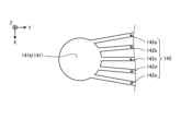
図12は、連通路14における第2部位142の他の構成例を示す模式的な斜視図である。具体的には、図12には、第2部材20の上面(第4面)のうち第2部位142の周辺部分を拡大して示している。
Figure 12 is a schematic perspective view showing another example of the configuration of the
図12に示すように、第2部位142は、複数(ここでは、5つ)の個別通路142a~142eを有する。複数の個別通路142a~142eは、それぞれ第1部位141と作動領域100とを接続する。すなわち、各個別通路142a~142eは、一端部において第1部位141の凹部141bに開口するとともに、他端部において第2溝形成領域120に開口する。12, the
各個別通路142a~142eの通路断面積は、第1部位141の通路断面積よりも小さい。一例として、各個別通路142a~142eの幅は、150μm以上400μm以下であり、高さは100μm以上1000μm以下である。The passage cross-sectional area of each of the
このように、連通路14の第2部位142は、通路断面積が小さい複数の個別通路142a~142eに分かれている。かかる構成とすることで、第2部位142を1本の通路で構成した場合と比較して毛細管力がより働きやすくなる。このため、たとえば放熱デバイス1の製造工程において作動領域100への作動液の注入をよりスムーズに行うことができる。また、放熱デバイス1の使用時において、作動領域100の高い圧力が連通路14や封止部5にかかり難くすることができる。
In this way, the
各個別通路142a~142eは、第1部位141から作動領域100に向かって直線状に延在している。この場合、各個別通路142a~142eの延長線上には、第2溝部21の第2凸部21bが位置していない。言い換えれば、各個別通路142a~142eは、各個別通路142a~142eを作動領域100に向かって延長した場合に、隣接する2つの第2凸部21bの間を通過する位置に設けられる。このような位置に個別通路142a~142eを設けることで、連通路14から作動領域100への作動液の流れが第2凸部21bによって妨げられ難くすることができる。Each
なお、図12では、個別通路142a~142eの全ての延長線上に、第2凸部21bが位置しない場合の例を示しているが、個別通路142a~142eのうち少なくとも1つの延長線上に、第2凸部21bが位置していなければよい。
Note that, although Figure 12 shows an example in which the second
図13~図16は、個別通路142a~142eの他の構成例を示す模式的な平面図である。
Figures 13 to 16 are schematic plan views showing other configuration examples of
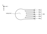
図13に示すように、個別通路142a~142eは、第2部材20の上面(第4面)の面内(XY平面)を蛇行しながら第2方向(Y方向)に延在していてもよい。かかる構成とすることで、個別通路142a~142eの流路抵抗を増加させることができる。したがって、作動領域100内の作動液の連通路14への浸入をさらに抑制することができる。
13, the
図14に示すように、個別通路142a~142eは、第1部位141から作動領域100に向かうにつれて互いに接近してもよい。また、図15に示すように、個別通路142a~142eは、第1部位141から作動領域100に向かうにつれて互いに離れてもよい。As shown in FIG 14, the
このように、複数の個別通路142a~142eは、必ずしも同一の方向に延在していることを要しない。複数の個別通路142a~142eの延在方向を異ならせることで、たとえば、各個別通路142a~142eから作動領域100に流入する作動液が作動領域100内に位置する第2凸部21bに極力ぶつからないように作動液の流れ方向が調整された連通路14を得ることができる。In this way, the
図16に示すように、個別通路142a~142eは、第1部位141から作動領域100に向かうにつれて通路断面積が小さくなるテーパ形状を有していてもよい。かかる構成とすることで、第1部位141から作動領域100に向かうにつれて毛細管力が徐々に大きくなるため、第1部位141から作動領域100に作動液がより流入し易くなる。逆に言えば、作動領域100から連通路14への作動液の浸入をさらに抑制することができる。16, the
次に、実施形態に係る放熱デバイス1の製造方法の一例について説明する。まず、第1部材10、第2部材20および中間部材30の原料を用い、ドクターブレード法またはロールコンパクション法等にてグリーンシートを形成し、複数のグリーンシートを積層することによって積層体を得る。Next, an example of a method for manufacturing the
つづいて、得られた積層体に対してレーザ加工や金型による打ち抜きを施すことにより、第1部材10、第2部材20および中間部材30の各成形体を得る。たとえば、積層体に対してレーザ加工を施すことにより、貫通孔141c,151c、複数の蒸気孔36および複数の還流孔37が形成された中間部材30の成形体を得ることができる。また、得られた積層体に対してレーザ加工を施すことにより、貫通孔141a,151aおよび第1溝形成領域110が形成された第1部材10の成形体が得られる。また、得られた積層体に対してレーザ加工を施すことにより、凹部141b,151b、溝部142b,152bおよび第2溝形成領域120が形成された第2部材20の成形体が得られる。Next, the obtained laminate is subjected to laser processing or die punching to obtain each of the molded bodies of the
つづいて、第1部材10、第2部材20および中間部材30の各成形体を、第2部材20、中間部材30および第1部材10の順番で積層して焼成することにより、第1部材10、第2部材20および中間部材30が一体化した容器2の焼結体が得られる。このように、第1部材10、第2部材20および中間部材30は一体成形される。したがって、接着剤等が不要であることから、信頼性の高い放熱デバイス1を得ることができる。Next, the molded bodies of the
なお、第1部材10、第2部材20および中間部材30の各成形体を得る方法としては、上述した方法に限らず、たとえば、グリーンシートに加工を施した後、グリーンシートを積層することによって各成形体を得るものであってもよい。また、上述した例では、第1部材10、第2部材20および中間部材30の各成形体を個別に作製した後、これらを積層することによって容器2の成形体を得ることとしたが、たとえば加工されたグリーンシートを順次積層することによって容器2の成形体を得ることとしてもよい。The method of obtaining each of the molded bodies of the
つづいて、たとえば連通路14,15のうちの一方から焼結体の内部に作動液を注入する。焼結体の内部に存在する気体は、作動液の注入に伴って連通路14,15のうちの他方から外部へ排出される。Next, the working fluid is injected into the sintered body, for example, through one of the
つづいて、真空ポンプ等の減圧装置を用い、連通路14,15を介して焼結体の内部を真空引きする。なお、焼結体の内部は真空状態であることが望ましいが、厳密に真空状態であることを要さず、たとえば真空状態に近い減圧状態であってもよい。つづいて、焼結体の内部が真空引きされた状態で連通路14,15を封止する。これにより、連通路14,15は、封止部5によって封止され、放熱デバイス1が得られる。Next, a vacuum pump or other decompression device is used to evacuate the inside of the sintered body through the communicating
上述してきたように、実施形態に係る熱デバイス(一例として、放熱デバイス1)は、相変態物質(一例として、作動液)の潜熱を利用した熱デバイスであって、セラミック製の容器(一例として、容器2)と、封止部(一例として、封止部5)とを有する。容器は、相変態物質が封入された相変態領域(一例として、作動領域100)と、相変態領域を囲む枠領域(一例として、枠領域200)と、相変態領域を外部と連通する連通路(一例として、連通路14,15)とを有する。封止部は、連通路を塞ぐ。連通路は、枠領域に位置する。As described above, the thermal device according to the embodiment (for example, heat dissipation device 1) is a thermal device that utilizes the latent heat of a phase change material (for example, a working fluid), and has a ceramic container (for example, container 2) and a sealing portion (for example, sealing portion 5). The container has a phase change region (for example, operating region 100) in which the phase change material is sealed, a frame region (for example, frame region 200) surrounding the phase change region, and a communication passage (for example,
したがって、実施形態に係る熱デバイスによれば、耐久性を向上させることができる。 Therefore, the thermal device according to the embodiment can improve durability.
なお、本開示による熱デバイスは、放熱デバイスに限定されない。たとえば、本開示による熱デバイスは、蓄熱材(相変態物質の一例)の相変態に伴う潜熱を熱エネルギーとして蓄える蓄熱デバイスであってもよい。この場合、蓄熱材は固液相変態を行うものや固固相変態を行うものが用いられる。このように、相変態物質は、必ずしも気液相変態を行うものであることを要しない。言い換えれば、相変態物質は、必ずしも液体であることを要さず、固体であってもよい。 Note that the thermal device according to the present disclosure is not limited to a heat dissipation device. For example, the thermal device according to the present disclosure may be a heat storage device that stores latent heat associated with the phase transformation of a heat storage material (an example of a phase change material) as thermal energy. In this case, the heat storage material used may be one that undergoes a solid-liquid phase transformation or a solid-solid phase transformation. In this way, the phase change material does not necessarily have to undergo a gas-liquid phase transformation. In other words, the phase change material does not necessarily have to be a liquid, and may be a solid.
今回開示された実施形態は全ての点で例示であって制限的なものではないと考えられるべきである。実に、上記した実施形態は多様な形態で具現され得る。また、上記の実施形態は、添付の請求の範囲およびその趣旨を逸脱することなく、様々な形態で省略、置換、変更されてもよい。The embodiments disclosed herein should be considered in all respects as illustrative and not restrictive. Indeed, the above-described embodiments may be embodied in various forms. Furthermore, the above-described embodiments may be omitted, substituted, or modified in various forms without departing from the scope and spirit of the appended claims.
1 放熱デバイス
5 封止部
10 第1部材
11 第1溝部
11a 第1凹部
11b 第1凸部
14,15 連通路
20 第2部材
21 第2溝部
21a 第2凹部
21b 第2凸部
30 中間部材
36 蒸気孔
37 還流孔
100 作動領域
141 第1部位
141a 貫通孔
141b 凹部
141c 貫通孔
142 第2部位
142a 個別通路
200 枠領域
REFERENCE SIGNS
Claims (12)
前記相変態物質が封入された相変態領域と、前記相変態領域を囲む枠領域と、前記枠領域に位置し、前記相変態領域を外部と連通する連通路とを有するセラミック製の容器と、
前記連通路を塞ぐ封止部と
を有し、
前記連通路は、
第1方向に延在して外部に開口する第1部位と、
前記第1方向と交差する第2方向に延在して前記相変態領域に開口する第2部位と
を有し、
前記第2部位は、前記第1部位の通路断面積よりも小さい複数の個別通路を有する、熱デバイス。 A thermal device that utilizes the latent heat of a phase change material,
a ceramic container having a phase change region in which the phase change material is sealed, a frame region surrounding the phase change region, and a communication passage located in the frame region and connecting the phase change region to the outside;
a sealing portion that closes the communication passage,
The communication passage is
A first portion extending in a first direction and opening to the outside;
a second portion extending in a second direction intersecting the first direction and opening into the phase transformation region;
having
The second portion has a plurality of individual passages each having a cross-sectional area smaller than a cross-sectional area of the passages in the first portion .
第1面と前記第1面の反対側に位置する第2面とを貫通する複数の還流孔を有する平板状の中間部材と、
前記中間部材の前記第1面と対向する第3面に第1溝部を有し、前記第3面の反対側に位置する第5面に熱源が配置される第1部材と、
前記中間部材の前記第2面と対向する第4面に第2溝部を有する第2部材と
を有し、
前記第1溝部と前記第2溝部とによって挟まれる前記相変態領域に、前記相変態物質としての作動液が位置する、請求項1~6のいずれか一つに記載の熱デバイス。 The container comprises:
a flat intermediate member having a first surface and a second surface opposite to the first surface, the flat intermediate member having a plurality of reflux holes penetrating the first surface and the second surface;
a first member having a first groove portion on a third surface facing the first surface of the intermediate member, and a heat source being disposed on a fifth surface located on the opposite side to the third surface;
a second member having a second groove portion on a fourth surface facing the second surface of the intermediate member,
7. The thermal device according to claim 1 , wherein a working fluid as the phase change material is located in the phase change region sandwiched between the first groove portion and the second groove portion.
前記中間部材における前記第1面と前記第1部材における前記第3面とによって挟まれる第1空間と、
前記中間部材における前記第2面と前記第2部材における前記第4面とによって挟まれる第2空間と
を有し、
前記第1部位は、前記容器を断面視した場合に、前記枠領域において前記第1空間および前記第2空間に跨がって延在しており、
前記第2部位は、前記容器を断面視した場合に、前記枠領域において前記第1空間および前記第2空間のうち前記第2空間側に位置している、請求項7に記載の熱デバイス。 The phase transformation region is
a first space defined by the first surface of the intermediate member and the third surface of the first member;
a second space sandwiched between the second surface of the intermediate member and the fourth surface of the second member,
the first portion extends across the first space and the second space in the frame region when the container is viewed in cross section,
The thermal device according to claim 7 , wherein the second portion is located on the second space side of the first space and the second space in the frame region when the container is viewed in cross section.
一方の前記連通路は、他の前記連通路との間で前記相変態領域を挟むように位置している、請求項6~11のいずれか一つに記載の熱デバイス。 At least two of the communication passages are provided,
12. The thermal device according to claim 6 , wherein one of the communication paths is positioned so as to sandwich the phase change region between itself and another of the communication paths.
Applications Claiming Priority (3)
| Application Number | Priority Date | Filing Date | Title |
|---|---|---|---|
| JP2021030210 | 2021-02-26 | ||
| JP2021030210 | 2021-02-26 | ||
| PCT/JP2022/006476 WO2022181453A1 (en) | 2021-02-26 | 2022-02-17 | Thermal device |
Publications (3)
| Publication Number | Publication Date |
|---|---|
| JPWO2022181453A1 JPWO2022181453A1 (en) | 2022-09-01 |
| JPWO2022181453A5 JPWO2022181453A5 (en) | 2023-11-16 |
| JP7635359B2 true JP7635359B2 (en) | 2025-02-25 |
Family
ID=83048925
Family Applications (1)
| Application Number | Title | Priority Date | Filing Date |
|---|---|---|---|
| JP2023502338A Active JP7635359B2 (en) | 2021-02-26 | 2022-02-17 | Thermal Devices |
Country Status (6)
| Country | Link |
|---|---|
| US (1) | US20240142179A1 (en) |
| EP (1) | EP4300572A4 (en) |
| JP (1) | JP7635359B2 (en) |
| KR (1) | KR20230136170A (en) |
| CN (1) | CN116940796A (en) |
| WO (1) | WO2022181453A1 (en) |
Families Citing this family (2)
| Publication number | Priority date | Publication date | Assignee | Title |
|---|---|---|---|---|
| WO2021263114A2 (en) * | 2020-06-25 | 2021-12-30 | Virginia Polytechnic Institute And State University | Planar bridging-droplet thermal diode |
| CN114608368A (en) * | 2020-12-08 | 2022-06-10 | 绍兴三花新能源汽车部件有限公司 | Heat exchanger |
Citations (5)
| Publication number | Priority date | Publication date | Assignee | Title |
|---|---|---|---|---|
| JP4035155B1 (en) | 2006-07-28 | 2008-01-16 | 株式会社渕上ミクロ | Heat pipe and manufacturing method thereof |
| JP2010243077A (en) | 2009-04-07 | 2010-10-28 | Sony Corp | Heat transport device manufacturing method, heat transport device, electronic apparatus, and caulking pin |
| WO2011149216A2 (en) | 2010-05-24 | 2011-12-01 | 한국과학기술원 | Flat heat spreader and manufacturing method therefor |
| WO2018139568A1 (en) | 2017-01-27 | 2018-08-02 | 古河電気工業株式会社 | Paper chamber |
| US20190247964A1 (en) | 2018-02-13 | 2019-08-15 | Asia Vital Components Co., Ltd. | Manufacturing method of vapor chamber water-filling section sealing structure |
Family Cites Families (14)
| Publication number | Priority date | Publication date | Assignee | Title |
|---|---|---|---|---|
| US2782010A (en) * | 1948-12-18 | 1957-02-19 | Modine Mfg Co | Heat exchanger |
| GB1467182A (en) | 1973-12-26 | 1977-03-16 | Burroughs Corp | Gas discharge display panel |
| JPS5732613Y2 (en) * | 1976-12-31 | 1982-07-17 | ||
| JPS5918631B2 (en) * | 1977-02-28 | 1984-04-28 | 日本特殊陶業株式会社 | Manufacturing method of ceramic heat pipe |
| JP2539663B2 (en) * | 1988-05-11 | 1996-10-02 | 株式会社フジクラ | High temperature ceramic heat pipe |
| US20020192531A1 (en) * | 1998-12-30 | 2002-12-19 | Joerg Zimmerman | Liquid reactant flow field plates for liquid feed fuel cells |
| JP2002081874A (en) * | 2000-09-11 | 2002-03-22 | Canon Inc | Plate type heat pipe and manufacturing method thereof |
| US7414843B2 (en) * | 2004-03-10 | 2008-08-19 | Intel Corporation | Method and apparatus for a layered thermal management arrangement |
| US8534348B2 (en) * | 2005-09-01 | 2013-09-17 | Molex Incorporated | Heat pipe and method for manufacturing same |
| JP2009024933A (en) * | 2007-07-19 | 2009-02-05 | Sony Corp | Thermal diffusion device and manufacturing method thereof |
| US20090178784A1 (en) * | 2008-01-15 | 2009-07-16 | Chin-Wen Wang | Manufacturing Method of Isothermal Vapor Chamber And Product Thereof |
| US20180156545A1 (en) * | 2016-12-05 | 2018-06-07 | Microsoft Technology Licensing, Llc | Vapor chamber with three-dimensional printed spanning structure |
| KR102442311B1 (en) * | 2017-02-24 | 2022-09-13 | 다이니폰 인사츠 가부시키가이샤 | Vapor chamber, electronic device, metal sheet for vapor chamber and manufacturing method of vapor chamber |
| TWI878179B (en) * | 2018-05-30 | 2025-03-21 | 日商大日本印刷股份有限公司 | Vapor chamber and electronic device |
-
2022
- 2022-02-17 WO PCT/JP2022/006476 patent/WO2022181453A1/en not_active Ceased
- 2022-02-17 CN CN202280016718.2A patent/CN116940796A/en active Pending
- 2022-02-17 JP JP2023502338A patent/JP7635359B2/en active Active
- 2022-02-17 US US18/279,010 patent/US20240142179A1/en active Pending
- 2022-02-17 EP EP22759489.2A patent/EP4300572A4/en active Pending
- 2022-02-17 KR KR1020237028742A patent/KR20230136170A/en active Pending
Patent Citations (5)
| Publication number | Priority date | Publication date | Assignee | Title |
|---|---|---|---|---|
| JP4035155B1 (en) | 2006-07-28 | 2008-01-16 | 株式会社渕上ミクロ | Heat pipe and manufacturing method thereof |
| JP2010243077A (en) | 2009-04-07 | 2010-10-28 | Sony Corp | Heat transport device manufacturing method, heat transport device, electronic apparatus, and caulking pin |
| WO2011149216A2 (en) | 2010-05-24 | 2011-12-01 | 한국과학기술원 | Flat heat spreader and manufacturing method therefor |
| WO2018139568A1 (en) | 2017-01-27 | 2018-08-02 | 古河電気工業株式会社 | Paper chamber |
| US20190247964A1 (en) | 2018-02-13 | 2019-08-15 | Asia Vital Components Co., Ltd. | Manufacturing method of vapor chamber water-filling section sealing structure |
Also Published As
| Publication number | Publication date |
|---|---|
| US20240142179A1 (en) | 2024-05-02 |
| EP4300572A1 (en) | 2024-01-03 |
| WO2022181453A1 (en) | 2022-09-01 |
| KR20230136170A (en) | 2023-09-26 |
| EP4300572A4 (en) | 2025-01-15 |
| JPWO2022181453A1 (en) | 2022-09-01 |
| CN116940796A (en) | 2023-10-24 |
Similar Documents
| Publication | Publication Date | Title |
|---|---|---|
| JP7693043B2 (en) | Heat dissipation materials | |
| JP7635359B2 (en) | Thermal Devices | |
| JP7635360B2 (en) | Thermal Devices | |
| CN107532860A (en) | High-performance two-phase cooling device | |
| JP7605657B2 (en) | Thermal Devices | |
| CN108534574A (en) | Intermediate piece of heat dissipation device and heat dissipation device thereof | |
| JP7571211B1 (en) | Vapor Chamber Device | |
| CN107801358B (en) | Pass-through structure of cooling unit | |
| JP7791301B2 (en) | Thermal Devices | |
| WO2025197761A1 (en) | Thermal device | |
| WO2023234042A1 (en) | Thermal device | |
| CN115136302B (en) | Heat dissipation components | |
| JP7061555B2 (en) | Ceramic joint and its manufacturing method | |
| WO2024204312A1 (en) | Thermal device | |
| CN207491438U (en) | Straight-through structure of cooling unit | |
| US20250123058A1 (en) | Multilayer high aspect ratio microchannel device | |
| WO2022025255A1 (en) | Heat conduction member | |
| WO2022025254A1 (en) | Heat conduction member | |
| JP2021196117A (en) | Heat conduction member and manufacturing method of the same | |
| JP2023118134A (en) | Thermally conductive member | |
| KR20040099532A (en) | Flat type heat transferring device having fill port formed in one body shape with main body |
Legal Events
| Date | Code | Title | Description |
|---|---|---|---|
| A521 | Request for written amendment filed |
Free format text: JAPANESE INTERMEDIATE CODE: A523 Effective date: 20230823 |
|
| A621 | Written request for application examination |
Free format text: JAPANESE INTERMEDIATE CODE: A621 Effective date: 20230823 |
|
| A131 | Notification of reasons for refusal |
Free format text: JAPANESE INTERMEDIATE CODE: A131 Effective date: 20241001 |
|
| A521 | Request for written amendment filed |
Free format text: JAPANESE INTERMEDIATE CODE: A523 Effective date: 20241129 |
|
| TRDD | Decision of grant or rejection written | ||
| A01 | Written decision to grant a patent or to grant a registration (utility model) |
Free format text: JAPANESE INTERMEDIATE CODE: A01 Effective date: 20250114 |
|
| A61 | First payment of annual fees (during grant procedure) |
Free format text: JAPANESE INTERMEDIATE CODE: A61 Effective date: 20250212 |
|
| R150 | Certificate of patent or registration of utility model |
Ref document number: 7635359 Country of ref document: JP Free format text: JAPANESE INTERMEDIATE CODE: R150 |