EP4300530B1 - Mittel- oder hochspannungsschutzschalter - Google Patents
Mittel- oder hochspannungsschutzschalter Download PDFInfo
- Publication number
- EP4300530B1 EP4300530B1 EP22182524.3A EP22182524A EP4300530B1 EP 4300530 B1 EP4300530 B1 EP 4300530B1 EP 22182524 A EP22182524 A EP 22182524A EP 4300530 B1 EP4300530 B1 EP 4300530B1
- Authority
- EP
- European Patent Office
- Prior art keywords
- lever arm
- arm
- linear
- linear lever
- vacuum interrupter
- Prior art date
- Legal status (The legal status is an assumption and is not a legal conclusion. Google has not performed a legal analysis and makes no representation as to the accuracy of the status listed.)
- Active
Links
Images


Classifications
-
- H—ELECTRICITY
- H01—ELECTRIC ELEMENTS
- H01H—ELECTRIC SWITCHES; RELAYS; SELECTORS; EMERGENCY PROTECTIVE DEVICES
- H01H33/00—High-tension or heavy-current switches with arc-extinguishing or arc-preventing means
- H01H33/60—Switches wherein the means for extinguishing or preventing the arc do not include separate means for obtaining or increasing flow of arc-extinguishing fluid
- H01H33/66—Vacuum switches
- H01H33/6606—Terminal arrangements
-
- H—ELECTRICITY
- H01—ELECTRIC ELEMENTS
- H01H—ELECTRIC SWITCHES; RELAYS; SELECTORS; EMERGENCY PROTECTIVE DEVICES
- H01H33/00—High-tension or heavy-current switches with arc-extinguishing or arc-preventing means
- H01H33/60—Switches wherein the means for extinguishing or preventing the arc do not include separate means for obtaining or increasing flow of arc-extinguishing fluid
- H01H33/66—Vacuum switches
- H01H33/664—Contacts; Arc-extinguishing means, e.g. arcing rings
-
- H—ELECTRICITY
- H01—ELECTRIC ELEMENTS
- H01H—ELECTRIC SWITCHES; RELAYS; SELECTORS; EMERGENCY PROTECTIVE DEVICES
- H01H33/00—High-tension or heavy-current switches with arc-extinguishing or arc-preventing means
- H01H33/60—Switches wherein the means for extinguishing or preventing the arc do not include separate means for obtaining or increasing flow of arc-extinguishing fluid
- H01H33/66—Vacuum switches
- H01H33/666—Operating arrangements
- H01H2033/6665—Details concerning the mounting or supporting of the individual vacuum bottles
-
- H—ELECTRICITY
- H01—ELECTRIC ELEMENTS
- H01H—ELECTRIC SWITCHES; RELAYS; SELECTORS; EMERGENCY PROTECTIVE DEVICES
- H01H33/00—High-tension or heavy-current switches with arc-extinguishing or arc-preventing means
- H01H33/60—Switches wherein the means for extinguishing or preventing the arc do not include separate means for obtaining or increasing flow of arc-extinguishing fluid
- H01H33/66—Vacuum switches
- H01H33/666—Operating arrangements
- H01H2033/6667—Details concerning lever type driving rod arrangements
Definitions
- the present invention relates to a medium voltage or high voltage circuit breaker, a drive for a medium voltage or high voltage circuit breaker, and a medium voltage or high voltage switchgear.
- Vacuum interrupters are widely known in the industry, in the applications of low-; medium-; high- voltage circuit breakers.
- EP2469561A1 describes a vacuum interrupter arrangement for a circuit breaker, comprising at least a first cylindrical shaped vacuum insert, within which a pair of corresponding electrical contacts is coaxially arranged, consisting of a fixed electrical contact which is attached to the vacuum insert and an axial movable electrical contact which is operated by a pushrod, wherein a second cylindrical shaped vacuum insert is coaxially arranged to the first cylindrical shaped vacuum insert, wherein both vacuum inserts are coaxially surrounded by an outer vacuum container in order to form a double contact gap version.
- Fig. 1 shows a standard design of a circuit breaker pole.
- the standard design of the circuit breaker pole has a housing 1, which provides for the proper positioning of internal parts, the upper terminal 2 and the lower terminal 6 provide an interface to the outer environment.
- the circuit breaker also has a vacuum interrupter (VI) 5 and a pushrod 7 transfers the movement of the actuator 8 into the VI.
- the VI 5 has one contact fixed contact 3 and one movable contact 4.
- the fixed contact 3 is both mechanically and electrically connected to the upper terminal 2.
- the moveable contact 4 is in electrical contact with lower contact 6. Mechanical fixation of the moveable contact 4 needs to allow for linear movement of this contact towards the fixed contact 3.
- the housing 1 is also used for improving the dielectric withstand of the whole interior assembly with respect to the surrounding electrical potentials. It is usually made of thermoplastic, duroplastic and/or thermoset material, which enables decreasing distances to the next phase(s) or grounded switchgear walls and provides for increasing creepage distances.
- a medium voltage or high voltage circuit breaker comprising:
- the first terminal is electrically connected to a fixed contact of the first vacuum interrupter
- the second terminal is electrically connected to a fixed contact of the second vacuum interrupter.
- the interconnection part is configured to be in electrical connection with a movable contact of the first vacuum interrupter and the interconnection part is configured to be in electrical connection with a movable contact of the second vacuum interrupter.
- the interconnection part is configured to provide a current path between the movable contacts.
- a first end of a first non-linear lever arm of the lever system is coupled to a pushrod of the movable contact of the first vacuum interrupter at a first lever arm first end pivot point, and a second end of the first lever arm is coupled to the operating rod at a centre pivot point.
- a first end of a second non-linear lever arm of the lever system is coupled to a pushrod of the movable contact of the second vacuum interrupter at a second lever arm first end pivot point, and a second end of the second lever arm is coupled to the operating rod at the centre pivot point.
- a part at the first end of the first non-linear lever arm is supported by the interconnection part and can slide linearly within a slot of the interconnection part or a part at the first end of the first non-linear lever arm is supported by the interconnection part and can move linearly with respect to a bearing of the interconnection part.
- a part at the first end of the second non-linear lever arm is supported by the interconnection part and can slide linearly within a slot of the interconnection part or a part at the first end of the second non-linear lever arm is supported by the interconnection part and can move linearly with respect to a bearing of the interconnection part.
- the actuator is configured to move the operating rod to move the second end of the first non-linear lever arm and the second end of the second non-linear lever arm such that the part at the first end of the first non-linear lever arm and the part at the first end of the second non-linear lever arm move simultaneously within their corresponding slots away from one another or with respect to their corresponding bearings away from one another.
- the second vacuum interrupter is connected in series with the first vacuum interrupter, and in a closed state current can flow from the first terminal to the second terminal when movable contacts of both vacuum interrupters are brought into contact with fixed contacts of both vacuum interrupters.
- a compact design is provided, because the movement required by the operating rod is minimised.
- the first non-linear lever arm comprises a first arm part connected to a second arm part.
- the first arm part of the first non-linear lever arm is angled to the second arm part of the first non-linear lever arm.
- An end of the first arm part is the first end of the first non-linear lever arm coupled to the pushrod of the movable contact of the first vacuum interrupter at the first lever arm first end pivot point.
- An end of the second arm part is the second end of the first lever arm coupled to the operating rod at the centre pivot point.
- the second non-linear lever arm comprises a first arm part connected to a second arm part.
- the first arm part of the second non-linear lever arm is angled to the second arm part of the second non-linear lever arm.
- An end of the first arm part is the first end of the second non-linear lever arm coupled to the pushrod of the movable contact of the second vacuum interrupter at the second lever arm first end pivot point.
- An end of the second arm part is the second end of the second lever arm coupled to the operating rod at the centre pivot point.
- a length of the first arm part of the first non-linear lever arm between the first end pivot point and the connection with the second arm part of the first non-linear lever arm is less than a length of the second arm part of the first non-linear lever arm between the centre pivot point and the connection with the first arm part of the first non-linear lever arm.
- a length of the first arm part of the second non-linear lever arm between the first end pivot point and the connection with the second arm part of the second non-linear lever arm is less than a length of the second arm part of the second non-linear lever arm between the centre pivot point and the connection with the first arm part of the second non-linear lever arm.
- the first arm part of the first non-linear lever arm is angled to the second arm part of the first non-linear lever arm at an obtuse angle.
- the first arm part of the second non-linear lever arm is angled to the second arm part of the second non-linear lever arm at an obtuse angle.
- the first arm part of the first non-linear lever arm is angled to the second arm part of the first non-linear lever arm at an angle substantially equal to 90 degrees.
- the first arm part of the second non-linear lever arm is angled to the second arm part of the second non-linear lever arm at an angle substantially equal to 90 degrees.
- the second non-linear lever arm is a mirror image of the first non-linear lever arm.
- the second non-linear lever arm is not a mirror image of the first non-linear lever arm.
- the first vacuum interrupter is of a different design to the second vacuum interrupter.
- the interconnection part is configured to be in electrical connection with the movable contact of the first vacuum interrupter and the interconnection part is configured to be in electrical connection with the movable contact of the second vacuum interrupter during at least part of the transition from the open state to the closed state.
- the actuator in a transition from the closed state to the open state the actuator is configured to move the operating rod to move the second end of the first non-linear lever arm and the second end of the second non-linear lever arm such that the part at the first end of the first non-linear lever arm and the part at the first end of the second non-linear lever arm move simultaneously within their corresponding slots towards one another or with respect to their corresponding bearings towards one another.
- a drive for a medium voltage or high voltage circuit breaker comprises a first terminal, a second terminal, a first vacuum interrupter, a second vacuum interrupter.
- the first terminal is electrically connected to a fixed contact of the first vacuum interrupter, and the second terminal is electrically connected to a fixed contact of the second vacuum interrupter.
- this comprises:
- the interconnection part is configured to be in electrical connection with a movable contact of the first vacuum interrupter and the interconnection part is configured to be in electrical connection with a movable contact of the second vacuum interrupter.
- the interconnection part is configured to provide a current path between the movable contacts.
- a first end of a first non-linear lever arm of the lever system is configured to couple to a pushrod of the movable contact of the first vacuum interrupter at a first lever arm first end pivot point, and a second end of the first lever arm is coupled to the operating rod at a centre pivot point.
- a first end of a second non-linear lever arm of the lever system is configured to couple to a pushrod of the movable contact of the second vacuum interrupter at a second lever arm first end pivot point, and a second end of the second lever arm is coupled to the operating rod at the centre pivot point.
- a part at the first end of the first non-linear lever arm is supported by the interconnection part and can slide linearly within a slot of the interconnection part or a part at the first end of the first non-linear lever arm is supported by the interconnection part and can move linearly with respect to a bearing of the interconnection part.
- a part at the first end of the second non-linear lever arm is supported by the interconnection part and can slide linearly within a slot of the interconnection part or a part at the first end of the second non-linear lever arm is supported by the interconnection part and can move linearly with respect to a bearing of the interconnection part.
- the actuator is configured to move the operating rod in a first direction to move the second end of the first lever arm and the second end of the second lever arm such that the part at the first end of the first lever arm and the part at the first end of the second lever arm move simultaneously within their corresponding slots away from one another or with respect to their corresponding bearings away from one another.
- the actuator is configured to move the operating rod in a second direction opposite to the first direction to move the second end of the first non-linear lever arm and the second end of the second non-linear lever arm such that the part at the first end of the first non-linear lever arm and the part at the first end of the second non-linear lever arm move simultaneously within their corresponding slots towards one another or with respect to their corresponding bearings towards one another.
- the first non-linear lever arm comprises a first arm part connected to a second arm part.
- the first arm part of the first non-linear lever arm is angled to the second arm part of the first non-linear lever arm.
- An end of the first arm part is the first end of the first non-linear lever arm coupled to the pushrod of the movable contact of the first vacuum interrupter at the first lever arm first end pivot point.
- An end of the second arm part is the second end of the first lever arm coupled to the operating rod at the centre pivot point.
- the second non-linear lever arm comprises a first arm part connected to a second arm part.
- the first arm part of the second non-linear lever arm is angled to the second arm part of the second non-linear lever arm.
- An end of the first arm part is the first end of the second non-linear lever arm coupled to the pushrod of the movable contact of the second vacuum interrupter at the second lever arm first end pivot point.
- An end of the second arm part is the second end of the second lever arm coupled to the operating rod at the centre pivot point.
- a length of the first arm part of the first non-linear lever arm between the first end pivot point and the connection with the second arm part of the first non-linear lever arm is less than a length of the second arm part of the first non-linear lever arm between the centre pivot point and the connection with the first arm part of the first non-linear lever arm.
- a length of the first arm part of the second non-linear lever arm between the first end pivot point and the connection with the second arm part of the second non-linear lever arm is less than a length of the second arm part of the second non-linear lever arm between the centre pivot point and the connection with the first arm part of the second non-linear lever arm.
- the first arm part of the first non-linear lever arm is angled to the second arm part of the first non-linear lever arm at an obtuse angle.
- the first arm part of the second non-linear lever arm is angled to the second arm part of the second non-linear lever arm at an obtuse angle.
- the first arm part of the first non-linear lever arm is angled to the second arm part of the first non-linear lever arm at an angle substantially equal to 90 degrees.
- the first arm part of the second non-linear lever arm is angled to the second arm part of the second non-linear lever arm at an angle substantially equal to 90 degrees.
- the second non-linear lever arm is a mirror image of the first non-linear lever arm.
- the second non-linear lever arm is not a mirror image of the first non-linear lever arm.
- a medium voltage or high voltage switchgear comprising at least one circuit breaker according to the first aspect.
- an interconnection part which as part of a drive, and the interconnecting part is a part interconnecting two vacuum interrupters (VIs) that are electrically connected in series.
- This interconnection part interconnecting the two VIs is designed not only for current carrying functionality, but at the same time provides for improved heat exchange and provides for mechanical fixation of the movable parts like current carrying flexible part or sliding current connection to the movable contacts.
- the interconnecting part and provides for support means for a lever system that is used to move the movable contacts, and where the lever system uses non-linear lever arms to reduce the required stroke of an operating rod and reduce the size of the circuit breaker.
- the circuit breaker with the drive can be manufactured in this way, and also two existing vacuum interrupters can be coupled together by the interconnecting part, as part of a new drive, in order to provide for increased voltage capability and/or capability at an existing voltage with faster switching operation in an overall size that is minimized.
- a new drive design has a lever system that connects the pole actuator with pushrods of the two series connected vacuum interrupters, with non-linear lever arms. Using non-linear lever arms with an "elbow” or "knee” shape provides for a decreasing manipulation space needed to move the operating rod and/or adjust the forces needed for proper operation of the vacuum interrupters.
- a housing can surround the whole to improve the dielectric withstand between two phases/poles as well as for the higher mechanical strength.
- a new medium voltage or high voltage circuit breaker is now described along with the new drive for a medium voltage or high voltage circuit breaker.
- a medium voltage or high voltage circuit breaker is described with two vacuum interrupters in series with an interconnection part, as part of a drive, connecting them.
- the current new development can be utilized with more than two vacuum interrupters in series, with interconnection parts connecting adjacent vacuum interrupters.
- a medium voltage or high voltage circuit breaker comprises a first terminal 2, a second terminal 6, a first vacuum interrupter 5, a second vacuum interrupter 5, an interconnection part 9, an actuator 8. an operating rod 11, and a lever system 12.
- the first terminal is electrically connected to a fixed contact 3 of the first vacuum interrupter.
- the second terminal is electrically connected to a fixed contact 3 of the second vacuum interrupter.
- the interconnection part is configured to be in electrical connection with a movable contact 4 of the first vacuum interrupter and the interconnection part is configured to be in electrical connection with a movable contact 4 of the second vacuum interrupter, and the interconnection part is configured to provide a current path between the movable contacts.
- a first end of a first non-linear lever arm 22 of the lever system is coupled to a pushrod 7 of the movable contact of the first vacuum interrupter at a first lever arm first end pivot point, and a second end of the first lever arm is coupled to the operating rod at a centre pivot point.
- a first end of a second non-linear lever arm 22 of the lever system is coupled to a pushrod 7 of the movable contact of the second vacuum interrupter at a second lever arm first end pivot point, and a second end of the second lever arm is coupled to the operating rod at the centre pivot point.
- a part at the first end of the first non-linear lever arm is supported by the interconnection part and can slide linearly within a slot of the interconnection part or a part at the first end of the first non-linear lever arm is supported by the interconnection part and can move linearly with respect to a bearing of the interconnection part.
- a part at the first end of the second non-linear lever arm is supported by the interconnection part and can slide linearly within a slot of the interconnection part or a part at the first end of the second non-linear lever arm is supported by the interconnection part and can move linearly with respect to a bearing of the interconnection part.
- each pair of the non-linear lever arms has another axle that has ends that go into slots in opposite walls of the interconnection part enabling the ends of the non-linear lever arms to translate upwards and downwards as the non-linear lever arms are angled through the other ends of the lever arms being pulled sideways.
- the ends of the non-linear lever arms moving upwards and downwards are coupled to the ends movable contacts via pushrods 7, enabling the non-linear lever arms to move the movable contacts towards and away from the fixed contacts simultaneously.
- the push rod 7, the non-linear lever arms 22 of the lever system 12 and the operating rod 11 can all be of an insulating material (or one of them can be) in order that the actuator 8 is electrically isolated from the movable contacts.
- the actuator is configured to move the operating rod to move the second end of the first non-linear lever arm and the second end of the second non-linear lever arm such that the part at the first end of the first non-linear lever arm and the part at the first end of the second non-linear lever arm move simultaneously within their corresponding slots away from one another or with respect to their corresponding bearings away from one another.
- the first vacuum interrupter is identical to the second vacuum interrupter.
- the first non-linear lever arm comprises a first arm part connected to a second arm part, and the first arm part of the first non-linear lever arm is angled to the second arm part of the first non-linear lever arm.
- An end of the first arm part is the first end of the first non-linear lever arm coupled to the pushrod of the movable contact of the first vacuum interrupter at the first lever arm first end pivot point
- an end of the second arm part is the second end of the first lever arm coupled to the operating rod at the centre pivot point.
- the second non-linear lever arm comprises a first arm part connected to a second arm part, and the first arm part of the second non-linear lever arm is angled to the second arm part of the second non-linear lever arm.
- An end of the first arm part is the first end of the second non-linear lever arm coupled to the pushrod of the movable contact of the second vacuum interrupter at the second lever arm first end pivot point, and an end of the second arm part is the second end of the second lever arm coupled to the operating rod at the centre pivot point.
- a length (a) of the first arm part of the first non-linear lever arm between the first end pivot point and the connection with the second arm part of the first non-linear lever arm is less than a length (b) of the second arm part of the first non-linear lever arm between the centre pivot point and the connection with the first arm part of the first non-linear lever arm.
- a length (a) of the first arm part of the second non-linear lever arm between the first end pivot point and the connection with the second arm part of the second non-linear lever arm is less than a length (b) of the second arm part of the second non-linear lever arm between the centre pivot point and the connection with the first arm part of the second non-linear lever arm.
- the first arm part of the first non-linear lever arm is angled to the second arm part of the first non-linear lever arm at an obtuse angle
- the first arm part of the second non-linear lever arm is angled to the second arm part of the second non-linear lever arm at an obtuse angle
- the first arm part of the first non-linear lever arm is angled to the second arm part of the first non-linear lever arm at an angle substantially equal to 90 degrees
- the first arm part of the second non-linear lever arm is angled to the second arm part of the second non-linear lever arm at an angle substantially equal to 90 degrees
- the second non-linear lever arm is a mirror image of the first non-linear lever arm.
- the second non-linear lever arm is not a mirror image of the first non-linear lever arm.
- the first vacuum interrupter is of a different design to the second vacuum interrupter.
- the part at the first end of the first non-linear lever arm and the part at the first end of the second non-linear lever arm move simultaneously within their corresponding slots away from one another over the same distance or with respect to their corresponding bearings away from one another over the same distance.
- the ends of the non-linear lever arms can move within slots as shown in the figures, however the ends can move with respect to or in bearings or similar that are integrated into the interconnection part, which can lead to a reduction in friction with respect to movement in a slot.
- the part at the first end of the first non-linear lever arm and the part at the first end of the second non-linear lever arm move simultaneously within their corresponding slots away from one another over a different distance or with respect to their corresponding bearings away from one another over the different distance.
- the part at the first end of the first non-linear lever arm and the part at the first end of the second non-linear lever arm move simultaneously within their corresponding slots away from one another at different velocities or with respect to their corresponding bearings away from one another over at different velocities.
- the ends of the non-linear lever arms can move within slots or with respect to bearings or similar that are integrated into the interconnection part, to move the movable contacts over different distances to obtain different final gaps between the movable and fixed contacts for each vacuum interrupter and move the contacts at different velocities.
- the interconnection part is configured to be in electrical connection with the movable contact of the first vacuum interrupter and the interconnection part is configured to be in electrical connection with the movable contact of the second vacuum interrupter during at least part of the transition from the open state to the closed state.
- this can be provided via "sliding" current carrying elements 15, such as a spiral contact or multilamellar, or contact band that can be fixed between the movable stem of the movable contact and the interconnection part 9.
- a drive rod of a movable contact 4 that is coupled to a push rod 7, can slide within the sliding current carrying elements 15 and there is an electrical connection from the stem of the movable contact 4 to the interconnection part 9.
- the electrical connection can be always established, such that the movable contact is always in electrical connection with the interconnection part, but it can be only in electrical connection towards the end of its drive as it approaches the fixed contact and when it is in contact with the fixed contact.
- the interconnection part is configured to be in electrical connection with the movable contact of the first vacuum interrupter and the interconnection part is configured to be in electrical connection with the movable contact of the second vacuum interrupter.
- the actuator in a transition from the closed state to the open state the actuator is configured to move the operating rod to move the second end of the first non-linear lever arm and the second end of the second non-linear lever arm such that the part at the first end of the first non-linear lever arm and the part at the first end of the second non-linear lever arm move simultaneously within their corresponding slots towards one another or with respect to their corresponding bearings towards one another.
- one or more of the at least one wall of the interconnection part comprises ribs on the inner side and/or on the outer side.
- the interconnection part is open on a second side opposite to the first side.
- a mounting between the actuator and the housing comprises at least one supporting and insulating mean 10.
- a medium voltage or high voltage switchgear can comprise one or more of such a circuit breaker as described above.
- the circuit breaker comprises a first terminal 2, a second terminal 6, a first vacuum interrupter 5, a second vacuum interrupter 5, here the first terminal is electrically connected to a fixed contact 3 of the first vacuum interrupter, and the second terminal is electrically connected to a fixed contact 3 of the second vacuum interrupter.
- the drive itself comprises an interconnection part 9, an actuator 8, an operating rod 11, and a lever system 12.
- a first end of a second non-linear lever arm 22 of the lever system is configured to couple to a pushrod 7 of the movable contact of the second vacuum interrupter at a second lever arm first end pivot point, and a second end of the second lever arm is coupled to the operating rod at the centre pivot point.
- a part at the first end of the first non-linear lever arm is supported by the interconnection part and can slide linearly within a slot of the interconnection part or a part at the first end of the first non-linear lever arm is supported by the interconnection part and can move linearly with respect to a bearing of the interconnection part.
- a part at the first end of the second non-linear lever arm is supported by the interconnection part and can slide linearly within a slot of the interconnection part or a part at the first end of the second non-linear lever arm is supported by the interconnection part and can move linearly with respect to a bearing of the interconnection part.
- the actuator is configured to move the operating rod in a first direction to move the second end of the first lever arm and the second end of the second lever arm such that the part at the first end of the first lever arm and the part at the first end of the second lever arm move simultaneously within their corresponding slots away from one another.
- the actuator is configured to move the operating rod in a second direction opposite to the first direction to move the second end of the first non-linear lever arm and the second end of the second non-linear lever arm such that the part at the first end of the first non-linear lever arm and the part at the first end of the second non-linear lever arm move simultaneously within their corresponding slots towards one another or with respect to their corresponding bearings away from one another.
- the first non-linear lever arm comprises a first arm part connected to a second arm part, and the first arm part of the first non-linear lever arm is angled to the second arm part of the first non-linear lever arm.
- An end of the first arm part is the first end of the first non-linear lever arm coupled to the pushrod of the movable contact of the first vacuum interrupter at the first lever arm first end pivot point
- an end of the second arm part is the second end of the first lever arm coupled to the operating rod at the centre pivot point.
- the second non-linear lever arm comprises a first arm part connected to a second arm part, and the first arm part of the second non-linear lever arm is angled to the second arm part of the second non-linear lever arm.
- the first arm part of the first non-linear lever arm is angled to the second arm part of the first non-linear lever arm at an obtuse angle
- the first arm part of the second non-linear lever arm is angled to the second arm part of the second non-linear lever arm at an obtuse angle
- non-linear lever arms could be in the form of a triangular-like shape, where the sides of the triangle are of different lengths (a and b). This can provide for extra robustness, with the functionality of such triangle-like "levers" equivalent to that discussed for the non-linear lever arms.
- the part at the first end of the first non-linear lever arm and the part at the first end of the second non-linear lever arm move simultaneously within their corresponding slots towards one another over the same distance or with respect to their corresponding bearings towards one another over the same distance.
- the interconnection part is configured to be in electrical connection with the movable contact of the first vacuum interrupter and the interconnection part is configured to be in electrical connection with the movable contact of the second vacuum interrupter during at least part of the transition from the closed state to the open state.
- interconnection part is configured such that the current path between the movable contacts is provided by at least one wall of the interconnection part.
- one or more of the at least one wall of the interconnection part comprises ribs on the inner side and/or on the outer side.
- the interconnection part is open on a first side.
- the interconnection part is open on a second side opposite to the first side.
- the above drive can be coupled with two vacuum interrupters as a circuit breaker is first being manufactured.
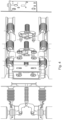
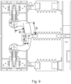
- Figs. 2-9 show a lever system (of the new drive) with linear lever arms, with Figs. 4-9 showing a lever system (of the new drive) with non-linear lever arms 22.
- the new double vacuum interrupter circuit breaker design can use two identical vacuum interrupters 5, that interconnect their current carrying parts through a specific part 9 called an interconnection part.
- the vacuum interrupters, together with their terminals and housing can also be termed poles.
- Mechanical fixation of all the other parts of both poles within the switchgear or other tanks, can be either done by adaptation of their housing 1, by fixing at the upper terminal 2 and lower terminal 6 or preferably both, i.e. housing as well as terminal fixation.
- the housing 1 may need to be supported by some supporting and insulating means 10, to withstand the mechanical loads originating from the actuator 8 as well as to provide sufficient insulating distance between terminals and grounded parts of the actuator 8 or surrounding parts.
- the lever system 12 has identical first and second non-linear lever arms 22 that are each attached to the operating rod at one end and at the other end the respective lever arms are couple to the movable contacts 4 via respective push rods 7.
- identical actual means that they are mirror images of each other.
- Another advantage of the double vacuum interrupter structure is that the distance between the fixed and the movable contacts of the vacuum interrupters can be half in each vacuum interrupter, compared to a distance needed in the situation of a single vacuum interrupter concept. Therefore, considering the same actuator design used in both cases, the opening speed for the two vacuum interrupter design will be much faster because of two gaps will open at the same time with same speed.
- non-linear lever arms 22 By having non-linear lever arms 22 rather than linear lever arms, a rotation of the non-linear lever arm as it is pushed or pulled by the operating rod leads to an increased linear translation of the end of the non-linear lever arm in its slot, and to an increased movement of the movable contacts.
- the operating rod 11 does not need to be moved so far, as regards if the lever arms were linear, and the operating rod can be shorter.
- the design of the non-linear levers not only decreases the distance required for the operating rod to move between open and closed position of the vacuum interrupters (VIs), but they create non-linearity of the switching force needed for optimum VIs switching.
- the interconnecting part 9 interconnecting the two vacuum interrupters can be created out of two identical or similar blocks made from metal, that can carry the current flow through both vacuum interrupters arranged in series as well as provide mechanical support to the mechanism operating the push rod. At the same time, such construction enables better heat dissipation through its opening on two sides, see Fig. 6 and transfer the current from the middle connection between both the vacuum interrupters.
- This design in shown clearly in Fig. 6 , where each block of the interconnecting part 9 in effect has a side wall with two slots in, which can be mechanical reinforced by a suitable means 14.
- the interconnecting block when constructed is open on both sides, enabling cooling air flow and on one of the open sides the operating rod 11 enters the interconnection part 9 and is couple to the non-linear levers 22 of the lever system 12.
- One end of the non-linear levers are then pushed and pulled by the operating rod 11 as it translates sideways, for example when it is rotated by the actuator 8 and passes through a threaded bearing and the other ends of the non-linear levers 22 of the lever system 12 slide within the slots perpendicularly to the translation of the operating rod 11.
- the interconnection part 9 can consist of two identical halves mated together. Its main functionality is to ensure proper electrical connection of the two vacuum interrupters connected in series as the whole current is flowing through the both half parts.
- the side walls of the interconnection part 9 and its top and bottom structures provides a large surface area in the design of interconnection part 9, which enables very good heat dissipation and can be designed in addition as heat sink with ribs on the inner and/or outer side, or a suitable surface roughness, or pins, or holes for air flow or all of these.
- two half designs create an opening on the operating rod side as well as on the opposite side and therefore enables good air or gas flow through this connection, further improving the above mentioned heat dissipation for example energy can be transferred away from the circuit breaker under current load.
- the double VI design can use a symmetrical/mirrored arrangement of the two VIs 5, and were non-linear levers 22 used are also identical in shape and positioned in a symmetrical arrangement as well.
- the direction of force on the operating rod 11, i.e. the rod 11 is pushed to close the VIs 5 and pulled to open them.
- the non-linear lever arms 22 of the lever system 12 were arranged facing in the opposite direction, it can be arranged that the rod is pushed to open the VIs and pulled to close the VIs.
- Fig, 4 shows a cross section of one drive, and a 3D view of three drives of for example a three phase system, with Fig. 5 showing the drive in VIs connected (switched on) and VIs disconnected (switched off) states.
Landscapes
- High-Tension Arc-Extinguishing Switches Without Spraying Means (AREA)
Claims (17)
- Ein Mittelspannungs- oder Hochspannungs-Leistungsschalter, umfassend:- einen ersten Anschluss (2);- einen zweiten Anschluss (6);- einen ersten Vakuumunterbrecher (5);- einen zweiten Vakuumunterbrecher (5);- ein Verbindungsteil (9);- einen Aktuator (8);- eine Betätigungsstange (11); und- ein Hebelsystem (12);wobei der erste Anschluss elektrisch mit einem Festkontakt (3) des ersten Vakuumunterbrechers verbunden ist und der zweite Anschluss elektrisch mit einem Festkontakt (3) des zweiten Vakuumunterbrechers verbunden ist,wobei das Verbindungsteil so eingerichtet ist, dass es in elektrischer Verbindung mit einem beweglichen Kontakt (4) des ersten Vakuumunterbrechers steht und das Verbindungsteil so eingerichtet ist, dass es in elektrischer Verbindung mit einem beweglichen Kontakt (4) des zweiten Vakuumunterbrechers steht, und wobei das Verbindungsteil so eingerichtet ist, dass es einen Strompfad zwischen den beweglichen Kontakten bereitstellt,wobei ein erstes Ende eines ersten nicht-linearen Hebelarms (22) des Hebelsystems mit einer Druckstange (7) des beweglichen Kontakts des ersten Vakuumunterbrechers an einem ersten Drehpunkt des ersten Hebelarms gekoppelt ist, und wobei ein zweites Ende des ersten Hebelarms mit der Betätigungsstange an einem mittleren Drehpunkt gekoppelt ist,wobei ein erstes Ende eines zweiten nicht-linearen Hebelarms (22) des Hebelsystems mit einer Druckstange (7) des beweglichen Kontakts des zweiten Vakuumunterbrechers an einem ersten Drehpunkt des zweiten Hebelarms gekoppelt ist, und wobei ein zweites Ende des zweiten Hebelarms mit der Betätigungsstange am mittleren Drehpunkt gekoppelt ist,wobei ein Teil am ersten Ende des ersten nicht-linearen Hebelarms durch das Verbindungsteil gestützt ist und sich linear innerhalb eines Schlitzes des Verbindungsteils bewegen kann oder ein Teil am ersten Ende des ersten nicht-linearen Hebelarms durch das Verbindungsteil gestützt ist und sich linear relativ zu einem Lager des Verbindungsteils bewegen kann,wobei ein Teil am ersten Ende des zweiten nicht-linearen Hebelarms durch das Verbindungsteil gestützt ist und sich linear innerhalb eines Schlitzes des Verbindungsteils bewegen kann oder ein Teil am ersten Ende des zweiten nicht-linearen Hebelarms durch das Verbindungsteil gestützt ist und sich linear relativ zu einem Lager des Verbindungsteils bewegen kann,wobei der Aktuator so eingerichtet ist, dass er bei einem Übergang von einem offenen Zustand in den geschlossenen Zustand die Betätigungsstange bewegt, um das zweite Ende des ersten nicht-linearen Hebelarms und das zweite Ende des zweiten nicht-linearen Hebelarms so zu bewegen, dass sich der Teil am ersten Ende des ersten nicht-linearen Hebelarms und der Teil am ersten Ende des zweiten nicht-linearen Hebelarms gleichzeitig innerhalb ihrer jeweiligen Schlitze oder relativ zu ihren jeweiligen Lagern voneinander weg bewegen.
- Leistungsschalter nach Anspruch 1, wobei der erste nicht-lineare Hebelarm einen ersten Armteil umfasst, der mit einem zweiten Armteil verbunden ist, wobei der erste Armteil des ersten nicht-linearen Hebelarms in einem Winkel zum zweiten Armteil des ersten nicht-linearen Hebelarms angeordnet ist, wobei ein Ende des ersten Armteils das erste Ende des ersten nicht-linearen Hebelarms ist, das mit der Druckstange des beweglichen Kontakts des ersten Vakuumunterbrechers am ersten Drehpunkt des ersten Hebelarms gekoppelt ist, und wobei ein Ende des zweiten Armteils das zweite Ende des ersten Hebelarms ist, das mit der Betätigungsstange am mittleren Drehpunkt gekoppelt ist; und wobei der zweite nicht-lineare Hebelarm einen ersten Armteil umfasst, der mit einem zweiten Armteil verbunden ist, wobei der erste Armteil des zweiten nicht-linearen Hebelarms in einem Winkel zum zweiten Armteil des zweiten nicht-linearen Hebelarms angeordnet ist, wobei ein Ende des ersten Armteils das erste Ende des zweiten nicht-linearen Hebelarms ist, das mit der Druckstange des beweglichen Kontakts des zweiten Vakuumunterbrechers am ersten Drehpunkt des zweiten Hebelarms gekoppelt ist, und wobei ein Ende des zweiten Armteils das zweite Ende des zweiten Hebelarms ist, das mit der Betätigungsstange am mittleren Drehpunkt gekoppelt ist.
- Leistungsschalter nach Anspruch 2, wobei eine Länge (a) des ersten Armteils des ersten nicht-linearen Hebelarms zwischen dem ersten Drehpunkt und der Verbindung mit dem zweiten Armteil des ersten nicht-linearen Hebelarms kleiner ist als eine Länge (b) des zweiten Armteils des ersten nicht-linearen Hebelarms zwischen dem mittleren Drehpunkt und der Verbindung mit dem ersten Armteil des ersten nicht-linearen Hebelarms; und wobei eine Länge (a) des ersten Armteils des zweiten nicht-linearen Hebelarms zwischen dem ersten Drehpunkt und der Verbindung mit dem zweiten Armteil des zweiten nicht-linearen Hebelarms kleiner ist als eine Länge (b) des zweiten Armteils des zweiten nicht-linearen Hebelarms zwischen dem mittleren Drehpunkt und der Verbindung mit dem ersten Armteil des zweiten nicht-linearen Hebelarms.
- Leistungsschalter nach einem der Ansprüche 2-3, wobei der erste Armteil des ersten nicht-linearen Hebelarms in einem stumpfen Winkel zum zweiten Armteil des ersten nicht-linearen Hebelarms angeordnet ist; und wobei der erste Armteil des zweiten nicht-linearen Hebelarms in einem stumpfen Winkel zum zweiten Armteil des zweiten nicht-linearen Hebelarms angeordnet ist.
- Leistungsschalter nach einem der Ansprüche 2-3, wobei der erste Armteil des ersten nicht-linearen Hebelarms in einem Winkel von im Wesentlichen 90 Grad zum zweiten Armteil des ersten nicht-linearen Hebelarms angeordnet ist; und wobei der erste Armteil des zweiten nicht-linearen Hebelarms in einem Winkel von im Wesentlichen 90 Grad zum zweiten Armteil des zweiten nicht-linearen Hebelarms angeordnet ist.
- Leistungsschalter nach einem der Ansprüche 1-5, wobei der zweite nicht-lineare Hebelarm ein Spiegelbild des ersten nicht-linearen Hebelarms ist.
- Leistungsschalter nach einem der Ansprüche 1-5, wobei der zweite nicht-lineare Hebelarm kein Spiegelbild des ersten nicht-linearen Hebelarms ist; und/oder der erste Vakuumunterbrecher eine andere Bauweise als der zweite Vakuumunterbrecher aufweist.
- Leistungsschalter nach einem der Ansprüche 1-7, wobei das Verbindungsteil so eingerichtet ist, dass es in elektrischer Verbindung mit dem beweglichen Kontakt des ersten Vakuumunterbrechers steht und das Verbindungsteil so eingerichtet ist, dass es in elektrischer Verbindung mit dem beweglichen Kontakt des zweiten Vakuumunterbrechers steht, zumindest während eines Teils des Übergangs vom offenen Zustand in den geschlossenen Zustand.
- Leistungsschalter nach einem der Ansprüche 1-8, wobei in einem Übergang vom geschlossenen Zustand in den offenen Zustand der Aktuator so eingerichtet ist, dass er die Betätigungsstange bewegt, um das zweite Ende des ersten nicht-linearen Hebelarms und das zweite Ende des zweiten nicht-linearen Hebelarms so zu bewegen, dass sich der Teil am ersten Ende des ersten nicht-linearen Hebelarms und der Teil am ersten Ende des zweiten nicht-linearen Hebelarms gleichzeitig innerhalb ihrer jeweiligen Schlitze oder relativ zu ihren jeweiligen Lagern aufeinander zu bewegen.
- Ein Antrieb für einen Mittelspannungs- oder Hochspannungs-Leistungsschalter, wobei der Leistungsschalter umfasst:- einen ersten Anschluss (2),- einen zweiten Anschluss (6),- einen ersten Vakuumunterbrecher (5),- einen zweiten Vakuumunterbrecher (5),wobei der erste Anschluss elektrisch mit einem Festkontakt (3) des ersten Vakuumunterbrechers verbunden ist,wobei der zweite Anschluss elektrisch mit einem Festkontakt (3) des zweiten Vakuumunterbrechers verbunden ist,und wobei der Antrieb umfasst:- ein Verbindungsteil (9),- einen Aktuator (8),- eine Betätigungsstange (11) und- ein Hebelsystem (12),wobei das Verbindungsteil so eingerichtet ist, dass es in elektrischer Verbindung mit einem beweglichen Kontakt (4) des ersten Vakuumunterbrechers steht und das Verbindungsteil so eingerichtet ist, dass es in elektrischer Verbindung mit einem beweglichen Kontakt (4) des zweiten Vakuumunterbrechers steht, und wobei das Verbindungsteil so eingerichtet ist, dass es einen Strompfad zwischen den beweglichen Kontakten bereitstellt,wobei ein erstes Ende eines ersten nicht-linearen Hebelarms (22) des Hebelsystems so eingerichtet ist, dass es an eine Druckstange (7) des beweglichen Kontakts des ersten Vakuumunterbrechers an einem ersten Drehpunkt des ersten Hebelarms gekoppelt ist, und wobei ein zweites Ende des ersten Hebelarms mit der Betätigungsstange an einem mittleren Drehpunkt gekoppelt ist,wobei ein erstes Ende eines zweiten nicht-linearen Hebelarms (22) des Hebelsystems so eingerichtet ist, dass es an eine Druckstange (7) des beweglichen Kontakts des zweiten Vakuumunterbrechers an einem ersten Drehpunkt des zweiten Hebelarms gekoppelt ist, und wobei ein zweites Ende des zweiten Hebelarms mit der Betätigungsstange am mittleren Drehpunkt gekoppelt ist,wobei ein Teil am ersten Ende des ersten nicht-linearen Hebelarms durch das Verbindungsteil gestützt ist und sich linear innerhalb eines Schlitzes des Verbindungsteils bewegen kann oder ein Teil am ersten Ende des ersten nicht-linearen Hebelarms durch das Verbindungsteil gestützt ist und sich linear relativ zu einem Lager des Verbindungsteils bewegen kann,wobei ein Teil am ersten Ende des zweiten nicht-linearen Hebelarms durch das Verbindungsteil gestützt ist und sich linear innerhalb eines Schlitzes des Verbindungsteils bewegen kann oder ein Teil am ersten Ende des zweiten nicht-linearen Hebelarms durch das Verbindungsteil gestützt ist und sich linear relativ zu einem Lager des Verbindungsteils bewegen kann,wobei in einem ersten Übergang der Aktuator so eingerichtet ist, dass er die Betätigungsstange in eine erste Richtung bewegt, um das zweite Ende des ersten Hebelarms und das zweite Ende des zweiten Hebelarms so zu bewegen, dass sich der Teil am ersten Ende des ersten Hebelarms und der Teil am ersten Ende des zweiten Hebelarms gleichzeitig innerhalb ihrer jeweiligen Schlitze oder relativ zu ihren jeweiligen Lagern voneinander weg bewegen,wobei in einem zweiten Übergang der Aktuator so eingerichtet ist, dass er die Betätigungsstange in eine zweite Richtung bewegt, die der ersten Richtung entgegengesetzt ist, um das zweite Ende des ersten nicht-linearen Hebelarms und das zweite Ende des zweiten nicht-linearen Hebelarms so zu bewegen, dass sich der Teil am ersten Ende des ersten nicht-linearen Hebelarms und der Teil am ersten Ende des zweiten nicht-linearen Hebelarms gleichzeitig innerhalb ihrer jeweiligen Schlitze oder relativ zu ihren jeweiligen Lagern aufeinander zu bewegen.
- Antrieb nach Anspruch 10, wobei der erste nicht-lineare Hebelarm einen ersten Armteil umfasst, der mit einem zweiten Armteil verbunden ist, wobei der erste Armteil des ersten nicht-linearen Hebelarms so eingerichtet ist, dass er in einem Winkel zum zweiten Armteil des ersten nicht-linearen Hebelarms angeordnet ist, wobei ein Ende des ersten Armteils das erste Ende des ersten nicht-linearen Hebelarms ist, das mit der Druckstange des beweglichen Kontakts des ersten Vakuumunterbrechers am ersten Drehpunkt des ersten Hebelarms gekoppelt ist, und wobei ein Ende des zweiten Armteils das zweite Ende des ersten Hebelarms ist, das mit der Betätigungsstange am mittleren Drehpunkt gekoppelt ist;
und wobei der zweite nicht-lineare Hebelarm einen ersten Armteil umfasst, der mit einem zweiten Armteil verbunden ist, wobei der erste Armteil des zweiten nicht-linearen Hebelarms so eingerichtet ist, dass er in einem Winkel zum zweiten Armteil des zweiten nicht-linearen Hebelarms angeordnet ist, wobei ein Ende des ersten Armteils das erste Ende des zweiten nicht-linearen Hebelarms ist, das mit der Druckstange des beweglichen Kontakts des zweiten Vakuumunterbrechers am ersten Drehpunkt des zweiten Hebelarms gekoppelt ist, und wobei ein Ende des zweiten Armteils das zweite Ende des zweiten Hebelarms ist, das mit der Betätigungsstange am mittleren Drehpunkt gekoppelt ist. - Antrieb nach Anspruch 11, wobei eine Länge (a) des ersten Armteils des ersten nicht-linearen Hebelarms zwischen dem ersten Drehpunkt und der Verbindung mit dem zweiten Armteil des ersten nicht-linearen Hebelarms kleiner ist als eine Länge (b) des zweiten Armteils des ersten nicht-linearen Hebelarms zwischen dem mittleren Drehpunkt und der Verbindung mit dem ersten Armteil des ersten nicht-linearen Hebelarms;
und wobei eine Länge (a) des ersten Armteils des zweiten nicht-linearen Hebelarms zwischen dem ersten Drehpunkt und der Verbindung mit dem zweiten Armteil des zweiten nicht-linearen Hebelarms kleiner ist als eine Länge (b) des zweiten Armteils des zweiten nicht-linearen Hebelarms zwischen dem mittleren Drehpunkt und der Verbindung mit dem ersten Armteil des zweiten nicht-linearen Hebelarms. - Antrieb nach einem der Ansprüche 11-12, wobei der erste Armteil des ersten nicht-linearen Hebelarms so eingerichtet ist, dass er in einem stumpfen Winkel zum zweiten Armteil des ersten nicht-linearen Hebelarms angeordnet ist;
und wobei der erste Armteil des zweiten nicht-linearen Hebelarms so eingerichtet ist, dass er in einem stumpfen Winkel zum zweiten Armteil des zweiten nicht-linearen Hebelarms angeordnet ist. - Antrieb nach einem der Ansprüche 11-12, wobei der erste Armteil des ersten nicht-linearen Hebelarms so eingerichtet ist, dass er in einem Winkel von im Wesentlichen 90 Grad zum zweiten Armteil des ersten nicht-linearen Hebelarms angeordnet ist;
und wobei der erste Armteil des zweiten nicht-linearen Hebelarms so eingerichtet ist, dass er in einem Winkel von im Wesentlichen 90 Grad zum zweiten Armteil des zweiten nicht-linearen Hebelarms angeordnet ist. - Antrieb nach einem der Ansprüche 10-14, wobei der zweite nicht-lineare Hebelarm so eingerichtet ist, dass er ein Spiegelbild des ersten nicht-linearen Hebelarms bildet.
- Antrieb nach einem der Ansprüche 10-14, wobei der zweite nicht-lineare Hebelarm so eingerichtet ist, dass er kein Spiegelbild des ersten nicht-linearen Hebelarms ist.
- Eine Mittelspannungs- oder Hochspannungsschaltanlage, umfassend mindestens einen Leistungsschalter nach einem der Ansprüche 1-9.
Priority Applications (3)
| Application Number | Priority Date | Filing Date | Title |
|---|---|---|---|
| EP22182524.3A EP4300530B1 (de) | 2022-07-01 | 2022-07-01 | Mittel- oder hochspannungsschutzschalter |
| US18/344,999 US20240006137A1 (en) | 2022-07-01 | 2023-06-30 | Medium Voltage or High Voltage Circuit Breaker |
| CN202310789603.3A CN117334515A (zh) | 2022-07-01 | 2023-06-30 | 中压或高压断路器 |
Applications Claiming Priority (1)
| Application Number | Priority Date | Filing Date | Title |
|---|---|---|---|
| EP22182524.3A EP4300530B1 (de) | 2022-07-01 | 2022-07-01 | Mittel- oder hochspannungsschutzschalter |
Publications (2)
| Publication Number | Publication Date |
|---|---|
| EP4300530A1 EP4300530A1 (de) | 2024-01-03 |
| EP4300530B1 true EP4300530B1 (de) | 2025-04-30 |
Family
ID=82492678
Family Applications (1)
| Application Number | Title | Priority Date | Filing Date |
|---|---|---|---|
| EP22182524.3A Active EP4300530B1 (de) | 2022-07-01 | 2022-07-01 | Mittel- oder hochspannungsschutzschalter |
Country Status (3)
| Country | Link |
|---|---|
| US (1) | US20240006137A1 (de) |
| EP (1) | EP4300530B1 (de) |
| CN (1) | CN117334515A (de) |
Families Citing this family (1)
| Publication number | Priority date | Publication date | Assignee | Title |
|---|---|---|---|---|
| US20250336627A1 (en) * | 2024-04-26 | 2025-10-30 | EMA Electromechanics, Inc. | Vacuum high voltage live tank circuit breaker free of fluid |
Family Cites Families (13)
| Publication number | Priority date | Publication date | Assignee | Title |
|---|---|---|---|---|
| CH477081A (fr) * | 1968-06-13 | 1969-08-15 | Gardy Particip App | Dispositif de coupure comprenant au moins une ampoule à contact dans le vide |
| US3597556A (en) * | 1970-01-16 | 1971-08-03 | Gen Electric | Vacuum-type circuit breaker with force-supplementing means for increasing current-carrying abilities |
| US3697819A (en) * | 1971-10-21 | 1972-10-10 | Gen Electric | Electric power distribution substation |
| JPS5624972B2 (de) * | 1973-11-05 | 1981-06-09 | ||
| US3970810A (en) * | 1975-03-06 | 1976-07-20 | General Electric Company | Electric circuit breaker comprising parallel-connected vacuum interrupters |
| US4087664A (en) * | 1975-08-29 | 1978-05-02 | I-T-E Imperial Corporation | Hybrid power circuit breaker |
| DE3300979A1 (de) * | 1983-01-12 | 1984-07-12 | Siemens AG, 1000 Berlin und 8000 München | Vakuumschalter mit zwei in reihe geschalteten schaltroehren je pol |
| EP0721197B1 (de) * | 1995-01-06 | 2002-03-06 | Gec Alsthom T & D Sa | Lastschalter mit zwei Löschkammern je Pol |
| JP3237445B2 (ja) * | 1995-03-27 | 2001-12-10 | 三菱電機株式会社 | 真空しゃ断装置 |
| JP2006019193A (ja) * | 2004-07-05 | 2006-01-19 | Toshiba Corp | 開閉装置 |
| EP2469561B1 (de) * | 2010-12-23 | 2017-04-05 | ABB Schweiz AG | Vakuumstromunterbrecheranordnung für einen Schutzschalter |
| EP2568493B1 (de) * | 2011-09-06 | 2015-12-16 | ABB Research Ltd. | Hochspannungsschaltungsvorrichtung |
| US10957505B2 (en) * | 2019-06-19 | 2021-03-23 | Eaton Intelligent Power Limited | Disconnect switch assemblies with a shared actuator that concurrently applies motive forces in opposing directions and related circuit breakers and methods |
-
2022
- 2022-07-01 EP EP22182524.3A patent/EP4300530B1/de active Active
-
2023
- 2023-06-30 CN CN202310789603.3A patent/CN117334515A/zh active Pending
- 2023-06-30 US US18/344,999 patent/US20240006137A1/en active Pending
Also Published As
| Publication number | Publication date |
|---|---|
| EP4300530A1 (de) | 2024-01-03 |
| CN117334515A (zh) | 2024-01-02 |
| US20240006137A1 (en) | 2024-01-04 |
Similar Documents
| Publication | Publication Date | Title |
|---|---|---|
| CN101728096B (zh) | 具有两个断路器的、具有用于致动断路器的可移动触头的共用装置的高压和中压开关设备 | |
| CN1645697B (zh) | 电气装置、配电室以及配电盘 | |
| CN101303946B (zh) | 电气开关装置及其导体组件和分流器组件 | |
| CN101651302A (zh) | 真空开关装置 | |
| CN1377515A (zh) | 一种气体绝缘开关装置 | |
| US7250583B2 (en) | Gas-insulated switchgear device | |
| EP4300530B1 (de) | Mittel- oder hochspannungsschutzschalter | |
| CN112840428A (zh) | 功率开关 | |
| KR20110079836A (ko) | 버스바 구간 스위치와 접지 스위치와 같은 2개의 스위치를 구비하고 이들 스위치의 가동접점에 공통하는 구동수단을 포함하는 전기 스위칭 장치 | |
| CN102714401B (zh) | 中压空气绝缘开关设备 | |
| CN103368095B (zh) | 电气装置及开关设备 | |
| CN101728784B (zh) | 开关设备以及用于该开关设备的控制机构 | |
| EP4297059B1 (de) | Mittel- oder hochspannungsschutzschalter | |
| EP2461339B1 (de) | Schutzschalterpol | |
| EP4276872A1 (de) | Mittelspannungsschaltvorrichtung | |
| CN113130249B (zh) | 断续器组件 | |
| EP3046129B1 (de) | Lastschaltsystem mit parallelem Strompfad | |
| EP3982389B1 (de) | Vakuumleistungsschalter | |
| JP7730391B2 (ja) | 入れ子式接点を有する断路器及び接地開閉器 | |
| US20240313512A1 (en) | Switchgear architecture | |
| US12087523B2 (en) | Solid dielectric insulated switchgear | |
| EP4661044A1 (de) | Mittelspannungsschaltvorrichtung | |
| EP4276869A1 (de) | Mittelspannungsschaltvorrichtung | |
| EP4030455A1 (de) | Mittelspannungsschaltvorrichtung | |
| EP2395525A1 (de) | Elektrischer Kontakt für Hochspannungs-Schutzschalter |
Legal Events
| Date | Code | Title | Description |
|---|---|---|---|
| PUAI | Public reference made under article 153(3) epc to a published international application that has entered the european phase |
Free format text: ORIGINAL CODE: 0009012 |
|
| STAA | Information on the status of an ep patent application or granted ep patent |
Free format text: STATUS: THE APPLICATION HAS BEEN PUBLISHED |
|
| AK | Designated contracting states |
Kind code of ref document: A1 Designated state(s): AL AT BE BG CH CY CZ DE DK EE ES FI FR GB GR HR HU IE IS IT LI LT LU LV MC MK MT NL NO PL PT RO RS SE SI SK SM TR |
|
| STAA | Information on the status of an ep patent application or granted ep patent |
Free format text: STATUS: REQUEST FOR EXAMINATION WAS MADE |
|
| 17P | Request for examination filed |
Effective date: 20240522 |
|
| RBV | Designated contracting states (corrected) |
Designated state(s): AL AT BE BG CH CY CZ DE DK EE ES FI FR GB GR HR HU IE IS IT LI LT LU LV MC MK MT NL NO PL PT RO RS SE SI SK SM TR |
|
| GRAP | Despatch of communication of intention to grant a patent |
Free format text: ORIGINAL CODE: EPIDOSNIGR1 |
|
| STAA | Information on the status of an ep patent application or granted ep patent |
Free format text: STATUS: GRANT OF PATENT IS INTENDED |
|
| INTG | Intention to grant announced |
Effective date: 20250128 |
|
| GRAS | Grant fee paid |
Free format text: ORIGINAL CODE: EPIDOSNIGR3 |
|
| GRAA | (expected) grant |
Free format text: ORIGINAL CODE: 0009210 |
|
| STAA | Information on the status of an ep patent application or granted ep patent |
Free format text: STATUS: THE PATENT HAS BEEN GRANTED |
|
| AK | Designated contracting states |
Kind code of ref document: B1 Designated state(s): AL AT BE BG CH CY CZ DE DK EE ES FI FR GB GR HR HU IE IS IT LI LT LU LV MC MK MT NL NO PL PT RO RS SE SI SK SM TR |
|
| REG | Reference to a national code |
Ref country code: CH Ref legal event code: EP Ref country code: GB Ref legal event code: FG4D |
|
| REG | Reference to a national code |
Ref country code: IE Ref legal event code: FG4D |
|
| REG | Reference to a national code |
Ref country code: DE Ref legal event code: R096 Ref document number: 602022013792 Country of ref document: DE |
|
| REG | Reference to a national code |
Ref country code: NL Ref legal event code: MP Effective date: 20250430 |
|
| REG | Reference to a national code |
Ref country code: AT Ref legal event code: MK05 Ref document number: 1790875 Country of ref document: AT Kind code of ref document: T Effective date: 20250430 |
|
| PG25 | Lapsed in a contracting state [announced via postgrant information from national office to epo] |
Ref country code: FI Free format text: LAPSE BECAUSE OF FAILURE TO SUBMIT A TRANSLATION OF THE DESCRIPTION OR TO PAY THE FEE WITHIN THE PRESCRIBED TIME-LIMIT Effective date: 20250430 Ref country code: ES Free format text: LAPSE BECAUSE OF FAILURE TO SUBMIT A TRANSLATION OF THE DESCRIPTION OR TO PAY THE FEE WITHIN THE PRESCRIBED TIME-LIMIT Effective date: 20250430 Ref country code: PT Free format text: LAPSE BECAUSE OF FAILURE TO SUBMIT A TRANSLATION OF THE DESCRIPTION OR TO PAY THE FEE WITHIN THE PRESCRIBED TIME-LIMIT Effective date: 20250901 |
|
| PGFP | Annual fee paid to national office [announced via postgrant information from national office to epo] |
Ref country code: DE Payment date: 20250722 Year of fee payment: 4 |
|
| REG | Reference to a national code |
Ref country code: LT Ref legal event code: MG9D |
|
| PG25 | Lapsed in a contracting state [announced via postgrant information from national office to epo] |
Ref country code: NO Free format text: LAPSE BECAUSE OF FAILURE TO SUBMIT A TRANSLATION OF THE DESCRIPTION OR TO PAY THE FEE WITHIN THE PRESCRIBED TIME-LIMIT Effective date: 20250730 Ref country code: GR Free format text: LAPSE BECAUSE OF FAILURE TO SUBMIT A TRANSLATION OF THE DESCRIPTION OR TO PAY THE FEE WITHIN THE PRESCRIBED TIME-LIMIT Effective date: 20250731 |
|
| PG25 | Lapsed in a contracting state [announced via postgrant information from national office to epo] |
Ref country code: PL Free format text: LAPSE BECAUSE OF FAILURE TO SUBMIT A TRANSLATION OF THE DESCRIPTION OR TO PAY THE FEE WITHIN THE PRESCRIBED TIME-LIMIT Effective date: 20250430 Ref country code: NL Free format text: LAPSE BECAUSE OF FAILURE TO SUBMIT A TRANSLATION OF THE DESCRIPTION OR TO PAY THE FEE WITHIN THE PRESCRIBED TIME-LIMIT Effective date: 20250430 |
|
| PG25 | Lapsed in a contracting state [announced via postgrant information from national office to epo] |
Ref country code: BG Free format text: LAPSE BECAUSE OF FAILURE TO SUBMIT A TRANSLATION OF THE DESCRIPTION OR TO PAY THE FEE WITHIN THE PRESCRIBED TIME-LIMIT Effective date: 20250430 |
|
| PG25 | Lapsed in a contracting state [announced via postgrant information from national office to epo] |
Ref country code: HR Free format text: LAPSE BECAUSE OF FAILURE TO SUBMIT A TRANSLATION OF THE DESCRIPTION OR TO PAY THE FEE WITHIN THE PRESCRIBED TIME-LIMIT Effective date: 20250430 |
|
| PG25 | Lapsed in a contracting state [announced via postgrant information from national office to epo] |
Ref country code: AT Free format text: LAPSE BECAUSE OF FAILURE TO SUBMIT A TRANSLATION OF THE DESCRIPTION OR TO PAY THE FEE WITHIN THE PRESCRIBED TIME-LIMIT Effective date: 20250430 |
|
| PGFP | Annual fee paid to national office [announced via postgrant information from national office to epo] |
Ref country code: FR Payment date: 20250725 Year of fee payment: 4 |
|
| PG25 | Lapsed in a contracting state [announced via postgrant information from national office to epo] |
Ref country code: RS Free format text: LAPSE BECAUSE OF FAILURE TO SUBMIT A TRANSLATION OF THE DESCRIPTION OR TO PAY THE FEE WITHIN THE PRESCRIBED TIME-LIMIT Effective date: 20250731 |
|
| PG25 | Lapsed in a contracting state [announced via postgrant information from national office to epo] |
Ref country code: IS Free format text: LAPSE BECAUSE OF FAILURE TO SUBMIT A TRANSLATION OF THE DESCRIPTION OR TO PAY THE FEE WITHIN THE PRESCRIBED TIME-LIMIT Effective date: 20250830 |
|
| PG25 | Lapsed in a contracting state [announced via postgrant information from national office to epo] |
Ref country code: LV Free format text: LAPSE BECAUSE OF FAILURE TO SUBMIT A TRANSLATION OF THE DESCRIPTION OR TO PAY THE FEE WITHIN THE PRESCRIBED TIME-LIMIT Effective date: 20250430 |