EP4297059B1 - Mittel- oder hochspannungsschutzschalter - Google Patents
Mittel- oder hochspannungsschutzschalter Download PDFInfo
- Publication number
- EP4297059B1 EP4297059B1 EP22180589.8A EP22180589A EP4297059B1 EP 4297059 B1 EP4297059 B1 EP 4297059B1 EP 22180589 A EP22180589 A EP 22180589A EP 4297059 B1 EP4297059 B1 EP 4297059B1
- Authority
- EP
- European Patent Office
- Prior art keywords
- lever arm
- circuit breaker
- interconnection part
- vacuum interrupter
- interconnection
- Prior art date
- Legal status (The legal status is an assumption and is not a legal conclusion. Google has not performed a legal analysis and makes no representation as to the accuracy of the status listed.)
- Active
Links
Images


Classifications
-
- H—ELECTRICITY
- H01—ELECTRIC ELEMENTS
- H01H—ELECTRIC SWITCHES; RELAYS; SELECTORS; EMERGENCY PROTECTIVE DEVICES
- H01H33/00—High-tension or heavy-current switches with arc-extinguishing or arc-preventing means
- H01H33/60—Switches wherein the means for extinguishing or preventing the arc do not include separate means for obtaining or increasing flow of arc-extinguishing fluid
- H01H33/66—Vacuum switches
- H01H33/662—Housings or protective screens
-
- H—ELECTRICITY
- H01—ELECTRIC ELEMENTS
- H01H—ELECTRIC SWITCHES; RELAYS; SELECTORS; EMERGENCY PROTECTIVE DEVICES
- H01H33/00—High-tension or heavy-current switches with arc-extinguishing or arc-preventing means
- H01H33/60—Switches wherein the means for extinguishing or preventing the arc do not include separate means for obtaining or increasing flow of arc-extinguishing fluid
- H01H33/66—Vacuum switches
- H01H33/666—Operating arrangements
-
- H—ELECTRICITY
- H01—ELECTRIC ELEMENTS
- H01H—ELECTRIC SWITCHES; RELAYS; SELECTORS; EMERGENCY PROTECTIVE DEVICES
- H01H9/00—Details of switching devices, not covered by groups H01H1/00 - H01H7/00
- H01H9/52—Cooling of switch parts
-
- H—ELECTRICITY
- H01—ELECTRIC ELEMENTS
- H01H—ELECTRIC SWITCHES; RELAYS; SELECTORS; EMERGENCY PROTECTIVE DEVICES
- H01H9/00—Details of switching devices, not covered by groups H01H1/00 - H01H7/00
- H01H9/52—Cooling of switch parts
- H01H2009/523—Cooling of switch parts by using heat pipes
-
- H—ELECTRICITY
- H01—ELECTRIC ELEMENTS
- H01H—ELECTRIC SWITCHES; RELAYS; SELECTORS; EMERGENCY PROTECTIVE DEVICES
- H01H9/00—Details of switching devices, not covered by groups H01H1/00 - H01H7/00
- H01H9/52—Cooling of switch parts
- H01H2009/526—Cooling of switch parts of the high voltage switches
-
- H—ELECTRICITY
- H01—ELECTRIC ELEMENTS
- H01H—ELECTRIC SWITCHES; RELAYS; SELECTORS; EMERGENCY PROTECTIVE DEVICES
- H01H33/00—High-tension or heavy-current switches with arc-extinguishing or arc-preventing means
- H01H33/60—Switches wherein the means for extinguishing or preventing the arc do not include separate means for obtaining or increasing flow of arc-extinguishing fluid
- H01H33/66—Vacuum switches
- H01H33/666—Operating arrangements
- H01H2033/6665—Details concerning the mounting or supporting of the individual vacuum bottles
-
- H—ELECTRICITY
- H01—ELECTRIC ELEMENTS
- H01H—ELECTRIC SWITCHES; RELAYS; SELECTORS; EMERGENCY PROTECTIVE DEVICES
- H01H33/00—High-tension or heavy-current switches with arc-extinguishing or arc-preventing means
- H01H33/60—Switches wherein the means for extinguishing or preventing the arc do not include separate means for obtaining or increasing flow of arc-extinguishing fluid
- H01H33/66—Vacuum switches
- H01H33/666—Operating arrangements
- H01H2033/6667—Details concerning lever type driving rod arrangements
-
- H—ELECTRICITY
- H01—ELECTRIC ELEMENTS
- H01H—ELECTRIC SWITCHES; RELAYS; SELECTORS; EMERGENCY PROTECTIVE DEVICES
- H01H2225/00—Switch site location
- H01H2225/008—Two different sites for one circuit, e.g. for safety
Definitions
- the present invention relates to a medium voltage or high voltage circuit breaker, and a medium voltage or high voltage switchgear.
- JPH08264084A describes that a pair of links are each pivoted to first pins at one end and to second distant pins at the other and cross in a cruciform. It is described that in a breaking state, when an insulating rod is pushed upward by driving an operating part, a connector is pushed upward via a contact pressure spring, and the positions of the pins move upward. It is described that then the links pivoted to the pins are each pushed upward at one end while the other ends move in a direction in which they move apart. It is described that next, rollers are guided into slide motion by a guide groove, and operating rods move outward, forcing movable contacts into contact with corresponding fixed contacts. It is described that therefore, the links can be made longer without an increase in the area occupied, resulting in device miniaturization.
- the fixed contact 3 is both mechanically and electrically connected to the upper terminal 2.
- the moveable contact 4 is in electrical contact with lower contact 6. Mechanical fixation of the moveable contact 4 needs to allow for linear movement of this contact towards the fixed contact 3.
- the housing 1 is also used for improving the dielectric withstand of the whole interior assembly with respect to the surrounding electrical potentials. It is usually made of thermoplastic, duroplastic and/or thermoset material, which enables decreasing distances to the next phase(s) or grounded switchgear walls and provides for increasing creepage distances.
- a medium voltage or high voltage circuit breaker comprising:
- the first terminal is electrically connected to a fixed contact of the first vacuum interrupter.
- the second terminal is electrically connected to a fixed contact of the second vacuum interrupter.
- the interconnection part is configured to be in electrical connection with a movable contact 4 of the first vacuum interrupter and the interconnection part is configured to be in electrical connection with a movable contact of the second vacuum interrupter. In the closed state the movable contacts have been moved to be in contact with the respective fixed contacts.
- the interconnection part is configured to provide a current path between the movable contacts.
- a first end of a first lever arm of the lever system is coupled to the movable contact of the first vacuum interrupter, and a second end of the first lever arm is coupled to the operating rod.
- a first end of a second lever arm of the lever system is coupled to the movable contact of the second vacuum interrupter, and a second end of the second lever arm is coupled to the operating rod.
- a part at the first end of the first lever arm is supported by the interconnection part and can slide linearly within a slot of the interconnection part or a part at the first end of the first lever arm is supported by the interconnection part and can move linearly with respect to a bearing of the interconnection part.
- a part at the first end of the second lever arm is supported by the interconnection part and can slide linearly within a slot of the interconnection part or a part at the first end of the second lever arm is supported by the interconnection part and can move linearly with respect to a bearing of the interconnection part.
- the actuator is configured to move the operating rod to move the second end of the first lever arm and the second end of the second lever arm such that the part at the first end of the first lever arm and the part at the first end of the second lever arm move simultaneously within their corresponding slots away from one another or with respect to their corresponding bearings away from one another.
- the part at the first end of the first lever arm and the part at the first end of the second lever arm move simultaneously within their corresponding slots or with respect to their corresponding bearings away from one another over the same distance.
- the interconnection part is configured to be in electrical connection with the movable contact of the first vacuum interrupter and the interconnection part is configured to be in electrical connection with the movable contact of the second vacuum interrupter during at least part of the transition from the open state to the closed state.
- the interconnection part is configured to be in electrical connection with the movable contact of the first vacuum interrupter and the interconnection part is configured to be in electrical connection with the movable contact of the second vacuum interrupter during the transition from the open state to the closed state.
- the actuator in a transition from the closed state to the open state the actuator is configured to move the operating rod to move the second end of the first lever arm and the second end of the second lever arm such that the part at the first end of the first lever arm and the part at the first end of the second lever arm move simultaneously within their corresponding slots or with respect to their corresponding bearings towards one another.
- the part at the first end of the first lever arm and the part at the first end of the second lever arm move simultaneously within their corresponding slots or with respect to their corresponding bearings towards one another over the same distance.
- the interconnection part is configured to be in electrical connection with the movable contact of the first vacuum interrupter and the interconnection part is configured to be in electrical connection with the movable contact of the second vacuum interrupter during at least part of the transition from the closed state to the open state.
- the interconnection part is configured to be in electrical connection with the movable contact of the first vacuum interrupter and the interconnection part is configured to be in electrical connection with the movable contact of the second vacuum interrupter during the transition from the closed state to the open state.
- the current path between the movable contacts is provided by at least one wall of the interconnection part
- one or more of the at least one wall of the interconnection part comprises ribs on the inner side and/or on the outer side.
- the interconnection part is open on a first side.
- the interconnection part is open on a second side opposite to the first side.
- the interconnection part consists of several elements
- the circuit breaker further comprises a housing surrounding the first vacuum interrupter, the second vacuum interrupter and the interconnection part.
- the housing is spaced from the at least one wall of the interconnection part. This provides at least one gap.
- a mounting between the actuator and the housing comprises at least one support insulator or other mechanical structure that ensures sufficient mechanical strength during switching operations of the breaker.
- a series connection of two VIs each that can be designed for a lower voltage than a full voltage requirement of the overall circuit breaker, provides for an easier alternative to a single VI designed for higher voltage and provides for a more robust interruption due to a double gap arrangement provided by each VI.
- the vacuum interrupters connected in series are not of the same or equal design.
- lever system and/or housing and/or interconnection parts are not symmetrically designed and/or connected to both vacuum interrupters used.
- an interconnection part which is a part interconnecting two vacuum interrupters (VIs) that are electrically connected in series.
- This interconnection part interconnecting the two VIs is designed not only for current carrying functionality, but at the same time provides for improved heat exchange and provides for mechanical fixation of the movable parts like current carrying flexible part or sliding current connection to the movable contacts, and provides for support means for a lever system that is used to move the movable contacts.
- the housing is used to improve the dielectric withstand between two phases/poles as well as for the higher mechanical strength.
- the interconnecting part can be connected with a heat pipe device to lead the heat from that "hot spot" area to an area where the heat dissipation at the switchgear can be done. That will give the opportunity to increase further the rated current flow throughout the interconnecting part.
- the heat pipe can be placed even on both ends of the first and the second VI to lower the temperature on both pol end.
- a medium voltage or high voltage switchgear comprising at least one circuit breaker according to the first aspect.
- a new medium voltage or high voltage circuit breaker is now described.
- a medium voltage or high voltage circuit breaker is described with two vacuum interrupters in series with an interconnection part connecting them.
- the current new development can be utilized with more than two vacuum interrupters in series, with interconnection parts connecting adjacent vacuum interrupters.
- a medium voltage or high voltage circuit breaker comprises a first terminal 2 (also called an upper terminal), a second terminal 6 (also called a lower terminal), a first vacuum interrupter 5, and a second vacuum interrupter 5.
- the vacuum interrupters here can be identical, but need not be identical.
- the circuit breaker also comprises an interconnection part 9, an actuator 8, an operating rod 11, and a lever system 12.
- the first terminal is electrically connected to a fixed contact 3 of the first vacuum interrupter
- the second terminal is electrically connected to a fixed contact 3 of the second vacuum interrupter.
- the interconnection part is configured to be in electrical connection with a movable contact 4 of the first vacuum interrupter and the interconnection part is configured to be in electrical connection with a movable contact 4 of the second vacuum interrupter.
- the interconnection part is configured to provide a current path between the movable contacts.
- the movable contacts of both vacuum interrupters are moved towards the respective fixed contacts until in a closed state the movable contacts are in contact with the fixed contacts.
- a first end of a first lever arm of the lever system is coupled to the movable contact of the first vacuum interrupter, and a second end of the first lever arm is coupled to the operating rod.
- a first end of a second lever arm of the lever system is coupled to the movable contact of the second vacuum interrupter, and a second end of the second lever arm is coupled to the operating rod.
- a part at the first end of the first lever arm is supported by the interconnection part and can slide linearly within a slot of the interconnection part, or can move with respect to a bearing integrated into the interconnection part.
- a part at the first end of the second lever arm is supported by the interconnection part and can slide linearly within a slot of the interconnection part, or can move with respect to a bearing integrated into the interconnection part.
- each pair of the lever arms has another axle that has ends that go into slots in opposite walls of the interconnection part enabling the ends of the lever arms to translate upwards and downwards as the lever arms are angled through the other ends of the lever arms being pulled sideways.
- the ends of the lever arms moving upwards and downwards are coupled to the ends movable contacts via pushrods 7, enabling the lever arms to move the movable contacts towards and away from the fixed contacts simultaneously.
- the push rod 7, the lever arms of the lever system 12 and the operating rod can all be of an insulating material (or one of them can be) in order that the actuator is electrically isolated from the movable contacts.
- the actuator in a transition from an open state to the closed state the actuator is configured to move the operating rod to move the second end of the first lever arm and the second end of the second lever arm such that the part at the first end of the first lever arm and the part at the first end of the second lever arm move simultaneously within their corresponding slots away from one another or with respect to their corresponding bearings away from one another.
- the second vacuum interrupter is connected in series with the first vacuum interrupter, and in a closed state current can flow from the first terminal to the second terminal when movable contacts of both vacuum interrupters are brought into contact with fixed contacts of both vacuum interrupters.
- the first vacuum interrupter is identical to the second vacuum interrupter.
- the part at the first end of the first lever arm and the part at the first end of the second lever arm move simultaneously within their corresponding slots or with respect to their corresponding bearings away from one another over the same distance.
- the interconnection part is configured to be in electrical connection with the movable contact of the first vacuum interrupter and the interconnection part is configured to be in electrical connection with the movable contact of the second vacuum interrupter during at least part of the transition from the open state to the closed state.
- the interconnection part is configured to be in electrical connection with the movable contact of the first vacuum interrupter and the interconnection part is configured to be in electrical connection with the movable contact of the second vacuum interrupter.
- this can be provided via "sliding" current carrying elements 15, such as a spiral contact or multilamellar, or contact band that can be fixed between the movable stem of the movable contact and the interconnection part 9.
- a drive rod of a movable contact 4 that is coupled to a push rod 7, can slide within the sliding current carrying elements 15 and there is an electrical connection from the stem of the movable contact 4 to the interconnection part 9.
- the electrical connection can be always established, such that the movable contact is always in electrical connection with the interconnection part, but it can be only in electrical connection towards the end of its drive as it approaches the fixed contact and when it is in contact with the fixed contact.
- the actuator in a transition from the closed state to the open state the actuator is configured to move the operating rod to move the second end of the first lever arm and the second end of the second lever arm such that the part at the first end of the first lever arm and the part at the first end of the second lever arm move simultaneously within their corresponding slots or with respect to their corresponding bearings towards one another.
- the part at the first end of the first lever arm and the part at the first end of the second lever arm move simultaneously within their corresponding slots or with respect to their corresponding bearings towards one another over the same distance.
- the ends of the lever arms can move within slots as shown in the figures, however the ends can move with respect to or in bearings or similar that are integrated into the interconnection part, which can lead to a reduction in friction with respect to movement in a slot.
- the current path between the movable contacts is provided by at least one wall of the interconnection part
- one or more of the at least one wall of the interconnection part comprises ribs on the inner side and/or on the outer side.
- the interconnection part is open on a first side.
- the interconnection part is open on a second side opposite to the first side.
- the interconnection part consists of several elements.
- the interconnection part can be formed from several parts or elements, mechanically and electrically connected together.
- the circuit breaker further comprises a housing 1 surrounding the first vacuum interrupter, the second vacuum interrupter and at least partly also the interconnection part. This is shown in Fig. 2 , Figs. 4a-b , and Fig. 5 in specific examples.
- the housing is spaced from the at least one wall of the interconnection part to provide at least one gap 100.
- a mounting between the actuator and the housing comprises at least one support insulator or other insulated mechanical arrangement 10.
- the vacuum interrupters connected in series are not of the same or equal design.
- the lever system and/or housing and/or interconnection parts are not symmetrically designed and/or connected to both vacuum interrupters used.
- Such a circuit breaker can be utilized with a medium voltage or high voltage switchgear.
- the new double vacuum interrupter circuit breaker design uses two identical vacuum interrupters 5, that interconnect their current carrying parts through a specific part 9 called an interconnection part.
- the vacuum interrupters can also be termed poles. Mechanical fixation of all the other parts of both poles can be either done by adaptation of their housing 1, by fixing at the upper terminal 2 and lower terminal 6 or preferably both, i.e., housing as well as terminal fixation.
- the housing may need to be supported by some electrically insulated supporting parts 10, to withstand the mechanical loads originating from the actuator 8 as well as to provide sufficient insulating distance between terminals and grounded parts of the actuator 8 or surrounding parts.
- the lever system 12 has identical first and second lever arms that are each attached to the operating rod at one end and at the other end the respective lever arms are couple to the movable contacts 4 via respective push rods 7. It is to be noted that in this embodiment the two VIs are identical and the first and second lever arms are identical, however if the two Vls are not identical, then the first and second lever arms might also differ.
- the two identical Vls 5 can both be designed for nearly half rated voltage compared to a single vacuum interrupter design, but with the same short circuit interruption current performance as a single vacuum interrupter deign. Therefore, the advantage of such a structure is, that series combination of two existing vacuum interrupters can be used for a double voltage level, without the necessity to utilize one higher voltage vacuum interrupter, what could require to design a new single vacuum interrupter for a particular rated voltage level.
- Another advantage of the double vacuum interrupter structure is that the distance between the fixed and the movable contacts of the vacuum interrupters can be half in each vacuum interrupter, compared to a distance needed in the situation of a single vacuum interrupter concept. Therefore, considering the same actuator design used in both cases, the opening speed for the two vacuum interrupter designs will be much faster because of two gaps will open at the same time with same speed. Furthermore, each pushrod 7 needs to travel half the distance compared to a situation in a single VI concept
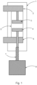
- the interconnecting part 9 interconnecting the two vacuum interrupters to be created out of two identical or similar blocks made from metal, that can carry the current flow through both vacuum interrupters arranged in series as well as provide mechanical support to the mechanism operating the push rod. At the same time, such construction enables better heat dissipation through its opening on two sides, see Fig. 3 and transfer the current from the middle connection between both the vacuum interrupters.
- This design is shown clearly in Fig. 3 , where each block of the interconnecting part 9 in effect has a side wall with two slots in, which can be mechanical reinforced by a suitable means 14.
- the interconnecting block when constructed is open on both sides, enabling cooling air flow and on one of the open sides the operating rod 11 enters the interconnection part 9 and is couple to the levers of the lever system 12.
- One end of the levers are then pushed and pulled by the operating rod 11 as it translates sideways, for example when it is rotated by the actuator 8 and passes through a threaded bearing and the other ends of the levers of the lever system 12 slide within the slots perpendicularly to the translation of the operating rod 11.
- the interconnection part 9 consists of two identical halves mated together. Its main functionality is to ensure proper electrical connection of the two vacuum interrupters connected in series as the whole current is flowing through the both half parts.
- the side walls of the interconnection part 9 and its top and bottom structures provides a large surface area in the design of interconnection part 9, which enables very good heat dissipation and can be designed in addition as heat sink with ribs on the inner and/or outer side, or a suitable surface roughness, or pins, or holes for air flow or all of these.
- two half designs create an opening on the operating rod side as well as on the opposite side and therefore enables good air or gas flow through this connection, further improving the above mentioned heat dissipation for example energy can be transferred away from the circuit breaker under current load.
- FIG. 3 show levers of a lever system 12, that translates or transforms movement of the operating rod 11 to the pushrods 7, providing necessary mechanical force, and adjusting the length of the movement which the pushrods need to take for proper on and off movement of vacuum interrupter contacts.
- the identical levers of the lever system 12 are connected to each vacuum interrupter 5 via the pushrod 7, simultaneous operation of both vacuum interrupters 5 is ensured. This is of importance for successful interruption.
- Both levers of the operating system 12 are then connected to the operating rod 11 at the connection point/part 13.
- levers As detailed above, when we discuss both levers this refers to a lever driving the movable contact of one vacuum interrupter and one lever driving the movable contact of the other vacuum interrupter, but in fact each of these driving levers can be in the form of a pair of levers.
- the interconnection part 9 serves at the same time as a mechanical structure for the operating mechanism (levers). As the interconnection part 9 may not have sufficient mechanical strength on top of its electrical properties, additional mechanical reinforcement 14 (e.g. sliding bearing) parts might be necessary, but only in places of highest mechanical load or expected friction, i.e. in the closing or opening operation where the levers 12 are moving.
- the interconnection part 9 can be built from two blocks, which can also be termed half shells. It is to be noted that each separate half shell construction enables easy insertion of parts separately and thus ensures a smooth assembly process during production of the pole.
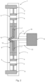
- Figs. 4a and 4b show cross-sections of a pole assembly design of the interconnection part 9 together with two vacuum interrupters 5, pushrods 7, levers of the lever system 12, operating rod 11 from the actuator 8 and their housing 1.
- the housing 1 can also be constructed using the half shell principle as for the interconnection part 9, making the whole assembly very modular.
- a feature of this design is the fact that the housing shells 1 cover, at least partly, the interconnection part 9, and this helps increase the dielectric performance and further strengthens the mechanical robustness of the full assembly.
- a best dielectric performance can be achieved when the two housing shells 1 on each side are overlapping or connected (not shown in Fig. 4 ), to provide maximum dielectric coverage of the interconnection part 9 having full electric potential in case the two vacuum interrupters 5 are moved to an on position.
- Fig. 5 shows an exploded view of the main parts used within a single pole formed from two vacuum interrupters.
- a field steering part 30 can be placed above/around or partly around the fixed contacts 3 of the vacuum interrupters 5, and even a capacitor can be used, and additional steering electrodes 31 can be used and connected to the half shell design of the interconnection part 9 formed from two blocks and/or steering electrodes 32 can be connected to a floating shielding that is within the vacuum interrupter body.
- circuit breaker there can be a design of described circuit breaker, consisting of different VI designs connected in series, i.e. the two VIs used are not identical. This might be needed in order to achieve required dielectric and/or short-circuit current performance. They may also result in a need to have asymmetrical lever system and/or housing and/or interconnection part.
Landscapes
- High-Tension Arc-Extinguishing Switches Without Spraying Means (AREA)
Claims (16)
- Ein Mittelspannungs- oder Hochspannungs-Leistungsschalter, umfassend:- einen ersten Anschluss (2);- einen zweiten Anschluss (6);- einen ersten Vakuumunterbrecher (5);- einen zweiten Vakuumunterbrecher (5);- ein Verbindungsteil (9);- einen Antrieb (8);- eine Betätigungsstange (11); und- ein Hebelsystem (12);wobei der erste Anschluss elektrisch mit einem Festkontakt (3) des ersten Vakuumunterbrechers verbunden ist, und wobei der zweite Anschluss elektrisch mit einem Festkontakt (3) des zweiten Vakuumunterbrechers verbunden ist; wobei das Verbindungsteil so ausgeführt ist, dass es in elektrischem Kontakt mit einem beweglichen Kontakt (4) des ersten Vakuumunterbrechers und in elektrischem Kontakt mit einem beweglichen Kontakt (4) des zweiten Vakuumunterbrechers ist, wenn sich der Leistungsschalter in einem geschlossenen Zustand befindet, in dem die beweglichen Kontakte mit den jeweiligen Festkontakten in Berührung sind, und wobei das Verbindungsteil dazu eingerichtet ist, einen Strompfad zwischen den beweglichen Kontakten bereitzustellen;wobei ein erstes Ende eines ersten Hebelarms des Hebelsystems mit dem beweglichen Kontakt des ersten Vakuumunterbrechers gekoppelt ist, und wobei ein zweites Ende des ersten Hebelarms mit der Betätigungsstange gekoppelt ist; wobei ein erstes Ende eines zweiten Hebelarms des Hebelsystems mit dem beweglichen Kontakt des zweiten Vakuumunterbrechers gekoppelt ist, und wobei ein zweites Ende des zweiten Hebelarms mit der Betätigungsstange gekoppelt ist;wobei ein Teil am ersten Ende des ersten Hebelarms durch das Verbindungsteil abgestützt ist und sich linear in einem Schlitz des Verbindungsteils bewegen kann oder ein Teil am ersten Ende des ersten Hebelarms durch das Verbindungsteil abgestützt ist und sich linear relativ zu einem Lager des Verbindungsteils bewegen kann;wobei ein Teil am ersten Ende des zweiten Hebelarms durch das Verbindungsteil abgestützt ist und sich linear in einem Schlitz des Verbindungsteils bewegen kann oder ein Teil am ersten Ende des zweiten Hebelarms durch das Verbindungsteil abgestützt ist und sich linear relativ zu einem Lager des Verbindungsteils bewegen kann; undwobei bei einem Übergang von einem offenen Zustand zum geschlossenen Zustand der Antrieb dazu eingerichtet ist, die Betätigungsstange zu bewegen, um das zweite Ende des ersten Hebelarms und das zweite Ende des zweiten Hebelarms so zu bewegen, dass sich das Teil am ersten Ende des ersten Hebelarms und das Teil am ersten Ende des zweiten Hebelarms innerhalb ihrer jeweiligen Schlitze oder relativ zu ihren jeweiligen Lagern gleichzeitig voneinander wegbewegen.
- Leistungsschalter nach Anspruch 1, wobei sich das Teil am ersten Ende des ersten Hebelarms und das Teil am ersten Ende des zweiten Hebelarms gleichzeitig innerhalb ihrer jeweiligen Schlitze oder relativ zu ihren jeweiligen Lagern über die gleiche Distanz voneinander wegbewegen.
- Leistungsschalter nach einem der Ansprüche 1 oder 2, wobei das Verbindungsteil so ausgeführt ist, dass es während mindestens eines Teils des Übergangs vom oder zum offenen Zustand in elektrischem Kontakt mit dem beweglichen Kontakt des ersten Vakuumunterbrechers und in elektrischem Kontakt mit dem beweglichen Kontakt des zweiten Vakuumunterbrechers steht.
- Leistungsschalter nach einem der Ansprüche 1 bis 3, wobei bei einem Übergang vom geschlossenen Zustand zum offenen Zustand der Antrieb dazu eingerichtet ist, die Betätigungsstange zu bewegen, um das zweite Ende des ersten Hebelarms und das zweite Ende des zweiten Hebelarms so zu bewegen, dass sich das Teil am ersten Ende des ersten Hebelarms und das Teil am ersten Ende des zweiten Hebelarms innerhalb ihrer jeweiligen Schlitze oder relativ zu ihren jeweiligen Lagern gleichzeitig aufeinander zubewegen.
- Leistungsschalter nach Anspruch 4, wobei sich das Teil am ersten Ende des ersten Hebelarms und das Teil am ersten Ende des zweiten Hebelarms gleichzeitig innerhalb ihrer jeweiligen Schlitze oder relativ zu ihren jeweiligen Lagern über die gleiche Distanz aufeinander zubewegen.
- Leistungsschalter nach einem der Ansprüche 4 bis 5, wobei das Verbindungsteil so ausgeführt ist, dass es während mindestens eines Teils des Übergangs vom geschlossenen Zustand zum offenen Zustand in elektrischem Kontakt mit dem beweglichen Kontakt des ersten Vakuumunterbrechers und in elektrischem Kontakt mit dem beweglichen Kontakt des zweiten Vakuumunterbrechers steht.
- Leistungsschalter nach einem der Ansprüche 1 bis 6, wobei der Strompfad zwischen den beweglichen Kontakten durch mindestens eine Wand des Verbindungsteils bereitgestellt wird.
- Leistungsschalter nach Anspruch 7, wobei eine oder mehrere der mindestens einen Wände des Verbindungsteils Rippen auf der Innenseite und/oder auf der Außenseite aufweisen.
- Leistungsschalter nach einem der Ansprüche 6 bis 8, wobei das Verbindungsteil an einer ersten Seite offen ist.
- Leistungsschalter nach Anspruch 9, wobei das Verbindungsteil an einer zweiten, der ersten Seite gegenüberliegenden Seite offen ist.
- Leistungsschalter nach einem der zuvor genannten Ansprüche, wobei das Verbindungsteil aus mehreren Elementen besteht.
- Leistungsschalter nach einem der Ansprüche 7 bis 11, ferner umfassend ein Gehäuse (1), das den ersten Vakuumunterbrecher, den zweiten Vakuumunterbrecher und das Verbindungsteil umgibt, wobei das Gehäuse von der mindestens einen Wand (oder von zumindest einem Abschnitt dieser Wand) des Verbindungsteils beabstandet ist, um mindestens einen Spalt (100) zu bilden.
- Leistungsschalter nach Anspruch 12, wobei eine Befestigung zwischen dem Antrieb und dem Gehäuse mindestens ein stützendes und isolierendes Teil (10) umfasst.
- Leistungsschalter nach einem der Ansprüche 1 bis 13, wobei die in Serie geschalteten Vakuumunterbrecher nicht von gleicher oder gleichartiger Ausführung sind.
- Leistungsschalter nach einem der Ansprüche 1 bis 14, wobei das Hebelsystem und/oder das Gehäuse und/oder die Verbindungsteile nicht symmetrisch ausgeführt und/oder nicht symmetrisch mit beiden verwendeten Vakuumunterbrechern verbunden sind.
- Eine Mittelspannungs- oder Hochspannungs-Schaltanlage, umfassend mindestens einen Leistungsschalter nach einem der Ansprüche 1 bis 15.
Priority Applications (3)
| Application Number | Priority Date | Filing Date | Title |
|---|---|---|---|
| EP22180589.8A EP4297059B1 (de) | 2022-06-23 | 2022-06-23 | Mittel- oder hochspannungsschutzschalter |
| CN202310738743.8A CN117292972A (zh) | 2022-06-23 | 2023-06-21 | 中压或高压断路器 |
| US18/212,729 US20230420202A1 (en) | 2022-06-23 | 2023-06-22 | Medium Voltage or High Voltage Circuit Breaker |
Applications Claiming Priority (1)
| Application Number | Priority Date | Filing Date | Title |
|---|---|---|---|
| EP22180589.8A EP4297059B1 (de) | 2022-06-23 | 2022-06-23 | Mittel- oder hochspannungsschutzschalter |
Publications (2)
| Publication Number | Publication Date |
|---|---|
| EP4297059A1 EP4297059A1 (de) | 2023-12-27 |
| EP4297059B1 true EP4297059B1 (de) | 2025-03-05 |
Family
ID=82258346
Family Applications (1)
| Application Number | Title | Priority Date | Filing Date |
|---|---|---|---|
| EP22180589.8A Active EP4297059B1 (de) | 2022-06-23 | 2022-06-23 | Mittel- oder hochspannungsschutzschalter |
Country Status (3)
| Country | Link |
|---|---|
| US (1) | US20230420202A1 (de) |
| EP (1) | EP4297059B1 (de) |
| CN (1) | CN117292972A (de) |
Family Cites Families (10)
| Publication number | Priority date | Publication date | Assignee | Title |
|---|---|---|---|---|
| US3597556A (en) * | 1970-01-16 | 1971-08-03 | Gen Electric | Vacuum-type circuit breaker with force-supplementing means for increasing current-carrying abilities |
| US3697819A (en) * | 1971-10-21 | 1972-10-10 | Gen Electric | Electric power distribution substation |
| US3970810A (en) * | 1975-03-06 | 1976-07-20 | General Electric Company | Electric circuit breaker comprising parallel-connected vacuum interrupters |
| DE3300979A1 (de) * | 1983-01-12 | 1984-07-12 | Siemens AG, 1000 Berlin und 8000 München | Vakuumschalter mit zwei in reihe geschalteten schaltroehren je pol |
| JP3237445B2 (ja) * | 1995-03-27 | 2001-12-10 | 三菱電機株式会社 | 真空しゃ断装置 |
| FR2923661B1 (fr) * | 2007-11-13 | 2010-04-30 | Areva T & D Sa | Appareil de commutation muni d'un disjoncteur et d'un sectionneur et comprenant des moyens d'entrainement communs |
| EP2469561B1 (de) * | 2010-12-23 | 2017-04-05 | ABB Schweiz AG | Vakuumstromunterbrecheranordnung für einen Schutzschalter |
| JP6044645B2 (ja) * | 2015-01-07 | 2016-12-14 | 株式会社明電舎 | 真空遮断器 |
| US10957505B2 (en) * | 2019-06-19 | 2021-03-23 | Eaton Intelligent Power Limited | Disconnect switch assemblies with a shared actuator that concurrently applies motive forces in opposing directions and related circuit breakers and methods |
| EP3896711B1 (de) * | 2020-04-14 | 2023-07-26 | Siemens Aktiengesellschaft | Dielektrische abschirmung für eine schaltvorrichtung |
-
2022
- 2022-06-23 EP EP22180589.8A patent/EP4297059B1/de active Active
-
2023
- 2023-06-21 CN CN202310738743.8A patent/CN117292972A/zh active Pending
- 2023-06-22 US US18/212,729 patent/US20230420202A1/en active Pending
Also Published As
| Publication number | Publication date |
|---|---|
| CN117292972A (zh) | 2023-12-26 |
| US20230420202A1 (en) | 2023-12-28 |
| EP4297059A1 (de) | 2023-12-27 |
Similar Documents
| Publication | Publication Date | Title |
|---|---|---|
| CN101728096B (zh) | 具有两个断路器的、具有用于致动断路器的可移动触头的共用装置的高压和中压开关设备 | |
| CN103828009B (zh) | 包括第一和第二动触头组件的真空开关装置及包括其的真空电气开关装置 | |
| US9035212B2 (en) | Switch having two sets of contact elements | |
| CN101097808A (zh) | 用于交流发电机的电路保护器圆柱凸轮的致动 | |
| EP4030457A1 (de) | Mittelspannungsschaltvorrichtung | |
| EP4300530B1 (de) | Mittel- oder hochspannungsschutzschalter | |
| EP4297059B1 (de) | Mittel- oder hochspannungsschutzschalter | |
| RU2516446C2 (ru) | Электрическое устройство переключения, содержащее два прерывателя, таких как шинный разъединитель и заземляющий разъединитель, и содержащее общее исполнительное устройство для подвижных контактов прерывателей | |
| EP4276870A1 (de) | Mittelspannungsschaltvorrichtung | |
| CN114080656A (zh) | 开关装置 | |
| US20230368993A1 (en) | Medium voltage switching apparatus | |
| EP4276872A1 (de) | Mittelspannungsschaltvorrichtung | |
| EP2461339B1 (de) | Schutzschalterpol | |
| EP3046129B1 (de) | Lastschaltsystem mit parallelem Strompfad | |
| EP3093866B1 (de) | Elektrische poleinheit für gasisolierte mittelspannungs-schutzschalter | |
| US11875955B2 (en) | Vacuum circuit breaker | |
| EP4276874B1 (de) | Mittelspannungsschaltvorrichtung | |
| US20250372324A1 (en) | Medium voltage switching apparatus | |
| EP4089704B1 (de) | Mittelspannungsschaltvorrichtung | |
| EP4283645B1 (de) | Mittelspannungsschaltvorrichtung | |
| EP4276869A1 (de) | Mittelspannungsschaltvorrichtung | |
| EP4641601A1 (de) | Schaltvorrichtung für elektrische systeme | |
| EP4030455A1 (de) | Mittelspannungsschaltvorrichtung | |
| EP4089705A1 (de) | Mittelspannungsschaltvorrichtung |
Legal Events
| Date | Code | Title | Description |
|---|---|---|---|
| PUAI | Public reference made under article 153(3) epc to a published international application that has entered the european phase |
Free format text: ORIGINAL CODE: 0009012 |
|
| STAA | Information on the status of an ep patent application or granted ep patent |
Free format text: STATUS: THE APPLICATION HAS BEEN PUBLISHED |
|
| AK | Designated contracting states |
Kind code of ref document: A1 Designated state(s): AL AT BE BG CH CY CZ DE DK EE ES FI FR GB GR HR HU IE IS IT LI LT LU LV MC MK MT NL NO PL PT RO RS SE SI SK SM TR |
|
| STAA | Information on the status of an ep patent application or granted ep patent |
Free format text: STATUS: REQUEST FOR EXAMINATION WAS MADE |
|
| 17P | Request for examination filed |
Effective date: 20240522 |
|
| RBV | Designated contracting states (corrected) |
Designated state(s): AL AT BE BG CH CY CZ DE DK EE ES FI FR GB GR HR HU IE IS IT LI LT LU LV MC MK MT NL NO PL PT RO RS SE SI SK SM TR |
|
| GRAP | Despatch of communication of intention to grant a patent |
Free format text: ORIGINAL CODE: EPIDOSNIGR1 |
|
| STAA | Information on the status of an ep patent application or granted ep patent |
Free format text: STATUS: GRANT OF PATENT IS INTENDED |
|
| INTG | Intention to grant announced |
Effective date: 20241016 |
|
| GRAS | Grant fee paid |
Free format text: ORIGINAL CODE: EPIDOSNIGR3 |
|
| GRAA | (expected) grant |
Free format text: ORIGINAL CODE: 0009210 |
|
| STAA | Information on the status of an ep patent application or granted ep patent |
Free format text: STATUS: THE PATENT HAS BEEN GRANTED |
|
| AK | Designated contracting states |
Kind code of ref document: B1 Designated state(s): AL AT BE BG CH CY CZ DE DK EE ES FI FR GB GR HR HU IE IS IT LI LT LU LV MC MK MT NL NO PL PT RO RS SE SI SK SM TR |
|
| REG | Reference to a national code |
Ref country code: GB Ref legal event code: FG4D |
|
| REG | Reference to a national code |
Ref country code: CH Ref legal event code: EP |
|
| REG | Reference to a national code |
Ref country code: IE Ref legal event code: FG4D |
|
| REG | Reference to a national code |
Ref country code: DE Ref legal event code: R096 Ref document number: 602022011331 Country of ref document: DE |
|
| PG25 | Lapsed in a contracting state [announced via postgrant information from national office to epo] |
Ref country code: RS Free format text: LAPSE BECAUSE OF FAILURE TO SUBMIT A TRANSLATION OF THE DESCRIPTION OR TO PAY THE FEE WITHIN THE PRESCRIBED TIME-LIMIT Effective date: 20250605 |
|
| PG25 | Lapsed in a contracting state [announced via postgrant information from national office to epo] |
Ref country code: FI Free format text: LAPSE BECAUSE OF FAILURE TO SUBMIT A TRANSLATION OF THE DESCRIPTION OR TO PAY THE FEE WITHIN THE PRESCRIBED TIME-LIMIT Effective date: 20250305 |
|
| PGFP | Annual fee paid to national office [announced via postgrant information from national office to epo] |
Ref country code: DE Payment date: 20250618 Year of fee payment: 4 |
|
| REG | Reference to a national code |
Ref country code: NL Ref legal event code: MP Effective date: 20250305 |
|
| PG25 | Lapsed in a contracting state [announced via postgrant information from national office to epo] |
Ref country code: ES Free format text: LAPSE BECAUSE OF FAILURE TO SUBMIT A TRANSLATION OF THE DESCRIPTION OR TO PAY THE FEE WITHIN THE PRESCRIBED TIME-LIMIT Effective date: 20250305 |
|
| REG | Reference to a national code |
Ref country code: LT Ref legal event code: MG9D |
|
| PG25 | Lapsed in a contracting state [announced via postgrant information from national office to epo] |
Ref country code: NO Free format text: LAPSE BECAUSE OF FAILURE TO SUBMIT A TRANSLATION OF THE DESCRIPTION OR TO PAY THE FEE WITHIN THE PRESCRIBED TIME-LIMIT Effective date: 20250605 |
|
| PG25 | Lapsed in a contracting state [announced via postgrant information from national office to epo] |
Ref country code: HR Free format text: LAPSE BECAUSE OF FAILURE TO SUBMIT A TRANSLATION OF THE DESCRIPTION OR TO PAY THE FEE WITHIN THE PRESCRIBED TIME-LIMIT Effective date: 20250305 |
|
| PG25 | Lapsed in a contracting state [announced via postgrant information from national office to epo] |
Ref country code: LV Free format text: LAPSE BECAUSE OF FAILURE TO SUBMIT A TRANSLATION OF THE DESCRIPTION OR TO PAY THE FEE WITHIN THE PRESCRIBED TIME-LIMIT Effective date: 20250305 |
|
| PGFP | Annual fee paid to national office [announced via postgrant information from national office to epo] |
Ref country code: FR Payment date: 20250627 Year of fee payment: 4 |
|
| PG25 | Lapsed in a contracting state [announced via postgrant information from national office to epo] |
Ref country code: GR Free format text: LAPSE BECAUSE OF FAILURE TO SUBMIT A TRANSLATION OF THE DESCRIPTION OR TO PAY THE FEE WITHIN THE PRESCRIBED TIME-LIMIT Effective date: 20250606 Ref country code: BG Free format text: LAPSE BECAUSE OF FAILURE TO SUBMIT A TRANSLATION OF THE DESCRIPTION OR TO PAY THE FEE WITHIN THE PRESCRIBED TIME-LIMIT Effective date: 20250305 |
|
| REG | Reference to a national code |
Ref country code: AT Ref legal event code: MK05 Ref document number: 1773752 Country of ref document: AT Kind code of ref document: T Effective date: 20250305 |
|
| PG25 | Lapsed in a contracting state [announced via postgrant information from national office to epo] |
Ref country code: NL Free format text: LAPSE BECAUSE OF FAILURE TO SUBMIT A TRANSLATION OF THE DESCRIPTION OR TO PAY THE FEE WITHIN THE PRESCRIBED TIME-LIMIT Effective date: 20250305 |
|
| PG25 | Lapsed in a contracting state [announced via postgrant information from national office to epo] |
Ref country code: SE Free format text: LAPSE BECAUSE OF FAILURE TO SUBMIT A TRANSLATION OF THE DESCRIPTION OR TO PAY THE FEE WITHIN THE PRESCRIBED TIME-LIMIT Effective date: 20250305 |
|
| PG25 | Lapsed in a contracting state [announced via postgrant information from national office to epo] |
Ref country code: SM Free format text: LAPSE BECAUSE OF FAILURE TO SUBMIT A TRANSLATION OF THE DESCRIPTION OR TO PAY THE FEE WITHIN THE PRESCRIBED TIME-LIMIT Effective date: 20250305 |
|
| PG25 | Lapsed in a contracting state [announced via postgrant information from national office to epo] |
Ref country code: PT Free format text: LAPSE BECAUSE OF FAILURE TO SUBMIT A TRANSLATION OF THE DESCRIPTION OR TO PAY THE FEE WITHIN THE PRESCRIBED TIME-LIMIT Effective date: 20250707 |
|
| PG25 | Lapsed in a contracting state [announced via postgrant information from national office to epo] |
Ref country code: PL Free format text: LAPSE BECAUSE OF FAILURE TO SUBMIT A TRANSLATION OF THE DESCRIPTION OR TO PAY THE FEE WITHIN THE PRESCRIBED TIME-LIMIT Effective date: 20250305 |
|
| PGFP | Annual fee paid to national office [announced via postgrant information from national office to epo] |
Ref country code: IT Payment date: 20250630 Year of fee payment: 4 |
|
| PG25 | Lapsed in a contracting state [announced via postgrant information from national office to epo] |
Ref country code: AT Free format text: LAPSE BECAUSE OF FAILURE TO SUBMIT A TRANSLATION OF THE DESCRIPTION OR TO PAY THE FEE WITHIN THE PRESCRIBED TIME-LIMIT Effective date: 20250305 |
|
| PG25 | Lapsed in a contracting state [announced via postgrant information from national office to epo] |
Ref country code: CZ Free format text: LAPSE BECAUSE OF FAILURE TO SUBMIT A TRANSLATION OF THE DESCRIPTION OR TO PAY THE FEE WITHIN THE PRESCRIBED TIME-LIMIT Effective date: 20250305 Ref country code: EE Free format text: LAPSE BECAUSE OF FAILURE TO SUBMIT A TRANSLATION OF THE DESCRIPTION OR TO PAY THE FEE WITHIN THE PRESCRIBED TIME-LIMIT Effective date: 20250305 |
|
| PG25 | Lapsed in a contracting state [announced via postgrant information from national office to epo] |
Ref country code: RO Free format text: LAPSE BECAUSE OF FAILURE TO SUBMIT A TRANSLATION OF THE DESCRIPTION OR TO PAY THE FEE WITHIN THE PRESCRIBED TIME-LIMIT Effective date: 20250305 |
|
| PG25 | Lapsed in a contracting state [announced via postgrant information from national office to epo] |
Ref country code: SK Free format text: LAPSE BECAUSE OF FAILURE TO SUBMIT A TRANSLATION OF THE DESCRIPTION OR TO PAY THE FEE WITHIN THE PRESCRIBED TIME-LIMIT Effective date: 20250305 |
|
| PG25 | Lapsed in a contracting state [announced via postgrant information from national office to epo] |
Ref country code: IS Free format text: LAPSE BECAUSE OF FAILURE TO SUBMIT A TRANSLATION OF THE DESCRIPTION OR TO PAY THE FEE WITHIN THE PRESCRIBED TIME-LIMIT Effective date: 20250705 |