EP4089704B1 - Mittelspannungsschaltvorrichtung - Google Patents
Mittelspannungsschaltvorrichtung Download PDFInfo
- Publication number
- EP4089704B1 EP4089704B1 EP21173739.0A EP21173739A EP4089704B1 EP 4089704 B1 EP4089704 B1 EP 4089704B1 EP 21173739 A EP21173739 A EP 21173739A EP 4089704 B1 EP4089704 B1 EP 4089704B1
- Authority
- EP
- European Patent Office
- Prior art keywords
- contact member
- movable
- fixed
- coupled
- arc contact
- Prior art date
- Legal status (The legal status is an assumption and is not a legal conclusion. Google has not performed a legal analysis and makes no representation as to the accuracy of the status listed.)
- Active
Links
Images


Classifications
-
- H—ELECTRICITY
- H01—ELECTRIC ELEMENTS
- H01H—ELECTRIC SWITCHES; RELAYS; SELECTORS; EMERGENCY PROTECTIVE DEVICES
- H01H31/00—Air-break switches for high tension without arc-extinguishing or arc-preventing means
- H01H31/02—Details
- H01H31/04—Interlocking mechanisms
- H01H31/08—Interlocking mechanisms for interlocking two or more parts of the mechanism for operating contacts
-
- H—ELECTRICITY
- H01—ELECTRIC ELEMENTS
- H01H—ELECTRIC SWITCHES; RELAYS; SELECTORS; EMERGENCY PROTECTIVE DEVICES
- H01H33/00—High-tension or heavy-current switches with arc-extinguishing or arc-preventing means
- H01H33/02—Details
- H01H33/04—Means for extinguishing or preventing arc between current-carrying parts
- H01H33/12—Auxiliary contacts on to which the arc is transferred from the main contacts
- H01H33/121—Load break switches
- H01H33/125—Load break switches comprising a separate circuit breaker
- H01H33/127—Load break switches comprising a separate circuit breaker movable with a sectionalising contact arm and operated by such movement
-
- H—ELECTRICITY
- H01—ELECTRIC ELEMENTS
- H01H—ELECTRIC SWITCHES; RELAYS; SELECTORS; EMERGENCY PROTECTIVE DEVICES
- H01H31/00—Air-break switches for high tension without arc-extinguishing or arc-preventing means
- H01H31/003—Earthing switches
-
- H—ELECTRICITY
- H01—ELECTRIC ELEMENTS
- H01H—ELECTRIC SWITCHES; RELAYS; SELECTORS; EMERGENCY PROTECTIVE DEVICES
- H01H31/00—Air-break switches for high tension without arc-extinguishing or arc-preventing means
- H01H31/02—Details
- H01H31/04—Interlocking mechanisms
-
- H—ELECTRICITY
- H01—ELECTRIC ELEMENTS
- H01H—ELECTRIC SWITCHES; RELAYS; SELECTORS; EMERGENCY PROTECTIVE DEVICES
- H01H3/00—Mechanisms for operating contacts
- H01H3/32—Driving mechanisms, i.e. for transmitting driving force to the contacts
- H01H3/42—Driving mechanisms, i.e. for transmitting driving force to the contacts using cam or eccentric
-
- H—ELECTRICITY
- H01—ELECTRIC ELEMENTS
- H01H—ELECTRIC SWITCHES; RELAYS; SELECTORS; EMERGENCY PROTECTIVE DEVICES
- H01H33/00—High-tension or heavy-current switches with arc-extinguishing or arc-preventing means
- H01H33/02—Details
- H01H33/022—Details particular to three-phase circuit breakers
-
- H—ELECTRICITY
- H01—ELECTRIC ELEMENTS
- H01H—ELECTRIC SWITCHES; RELAYS; SELECTORS; EMERGENCY PROTECTIVE DEVICES
- H01H33/00—High-tension or heavy-current switches with arc-extinguishing or arc-preventing means
- H01H33/02—Details
- H01H33/04—Means for extinguishing or preventing arc between current-carrying parts
- H01H33/12—Auxiliary contacts on to which the arc is transferred from the main contacts
- H01H33/121—Load break switches
- H01H33/122—Load break switches both breaker and sectionaliser being enclosed, e.g. in SF6-filled container
-
- H—ELECTRICITY
- H01—ELECTRIC ELEMENTS
- H01H—ELECTRIC SWITCHES; RELAYS; SELECTORS; EMERGENCY PROTECTIVE DEVICES
- H01H33/00—High-tension or heavy-current switches with arc-extinguishing or arc-preventing means
- H01H33/60—Switches wherein the means for extinguishing or preventing the arc do not include separate means for obtaining or increasing flow of arc-extinguishing fluid
- H01H33/66—Vacuum switches
- H01H33/666—Operating arrangements
- H01H33/6661—Combination with other type of switch, e.g. for load break switches
Definitions
- the present invention relates to a switching apparatus for medium voltage electric systems, more particularly to a load-break switch for medium voltage electric systems.
- Load-break switches are well known in the state of the art.
- These switching apparatuses which are generally used in secondary distribution electric grids, are capable of providing circuit-breaking functionalities (namely breaking and making a current) under specified circuit conditions (typically nominal conditions for breaking a current and nominal conditions or fault conditions for making a current) as well as providing circuit-disconnecting functionalities (namely grounding a load-side section of an electric circuit).
- Some load-break switches have been developed, in which electric poles are immersed in pressurized dry air or in an environment-friendly insulation gas, such as mixtures of oxygen, nitrogen, carbon dioxide and/or fluorinated gases.
- an environment-friendly insulation gas such as mixtures of oxygen, nitrogen, carbon dioxide and/or fluorinated gases.
- these switching apparatuses generally do not show fully satisfactory performances, particularly in terms of arc-quenching capabilities and dielectric insulation.
- the main aim of the present invention is to provide a switching apparatus for MV electric systems that allows solving or mitigating the above-mentioned technical problems.
- Another object of the present invention is to provide a switching apparatus showing high levels of reliability in operation.
- Another object of the present invention is to provide a switching apparatus having electric poles with high compactness and structural simplicity.
- Another object of the present invention is to provide a switching apparatus that can be easily manufactured at industrial level, at competitive costs with respect to the solutions of the state of the art.
- the present invention provides a switching apparatus, according to the following claim 1 and the related dependent claims.
- the switching apparatus of the invention comprises one or more electric poles.
- the switching apparatus comprises, for each electric pole, a movable contact assembly rotatable about a rotation axis.
- Said movable contact assembly comprises:
- the first main contact member is decoupled from the first and fourth fixed contact members
- the second main contact member is decoupled from the second and third fixed contact members
- the arc contact members are coupled one to another.
- the first main contact member is coupled to the fourth fixed contact member
- the second main contact member is coupled to the third fixed contact member
- the arc contact members are coupled one to another.
- the above-mentioned arc contact members comprise a fixed arc contact member and a movable arc contact member.
- the movable arc contact member can be coupled to or decoupled from the fixed arc contact member by moving along a translation axis perpendicular to said rotation axis.
- the switching apparatus comprises, for each electric pole, at least a track member having a track surface with a cam profile and at least a drive member solidly coupled with the movable arc contact member.
- Each drive member is adapted to slide along the track surface of a corresponding track member, upon a rotational movement of said movable contact assembly about said rotation axis.
- Each drive member actuates said movable arc contact member along a translation axis perpendicular to said rotation axis between a coupled position to and an uncoupled position from said fixed arc contact member, when sliding along said track surface.
- each drive member When the movable contact assembly is in said first end-of run position, each drive member is in a first position along said track surface.
- the drive member When the movable contact assembly is in said second end-of run position, the drive member is in a third position along said track surface.
- said second position is intermediate between said first and third positions.
- Each drive member slides along a first track surface portion with a cam profile, when moving between said first and second positions, and it slides along a second track surface portion with a cam profile, when moving between said second and third positions.
- Each drive member actuates the movable arc contact member to a coupled position to said fixed arc contact member, when said drive member is in said first position or in said second position or in said third position along said track surface.
- Each drive member actuates the movable arc contact member along said translation axis between a coupled position to and an uncoupled position from said fixed arc contact member, when sliding along said first track surface portion or said second track surface portion.
- each movable contact assembly comprises a cam mechanism coupled to the movable arc contact member.
- Said cam mechanism is adapted to press the movable arc contact member against the fixed arc contact member, when said movable arc contact member is coupled to said fixed arc contact member and said movable contact assembly is in said first end-of-run position or in said second end-of-run position.
- the cam mechanism comprises:
- the cam mechanism comprises a slider member coupled to the push member and couplable with one or more first cam surfaces or one or more second cam surfaces, when the movable contact assembly is in said first end-of-run position or in said second end-of-run position.
- the slider member exerts, on the push member, an actuation force directed to cause the compression of the spring member and the consequent pressing of the movable arc contact member against the fixed arc contact member, when said slider member is coupled to said one or more first cam surfaces or said one or more second cam surfaces.
- the cam mechanism comprises a lever member having a cam profile and couplable to said push member and to one or more first sliding surfaces or one or more second sliding surfaces, when the movable contact assembly is in said first end-of-run position or in said second end-of-run position.
- the lever member exerts, on the push member, an actuation force directed to cause the compression of the spring member and the consequent pressing of the movable arc contact member against the fixed arc contact member, when said lever member is coupled to said one or more first sliding surfaces or said one or more second sliding surfaces.
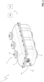
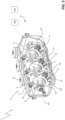
- the present invention relates to a switching apparatus 1 for medium voltage electric systems.
- MV medium voltage
- MV relates to operating voltages at electric power distribution level, which are higher than 1 kV AC and 1.5 kV DC up to some tens of kV, e.g. up to 72 kV AC and 100 kV DC.
- the switching apparatus 1 is particularly adapted to operate as a load-break switch. It is therefore designed for providing circuit-breaking functionalities under specified circuit conditions (normally nominal conditions for making a current and nominal conditions or fault conditions for making a current) as well as circuit-disconnecting functionalities, in particular grounding a load-side section of an electric circuit.
- the switching apparatus 1 comprises one or more electric poles 2.
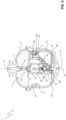
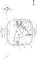
- the insulating housing 4 has an elongated shape (e.g. substantially cylindrical or parallelepiped-like) developing along a a main longitudinal axis A1 ( figure 1 ).
- the electric poles 2 are arranged side by side along the longitudinal axis A1 at corresponding transversal planes perpendicular the said longitudinal axis.
- the actuation assembly 30 of the switching apparatus may be realized according to solutions of known type. Therefore, in the following, it will be described only in relation to the aspects of interest of the invention, for the sake of brevity.
- the movable contact assembly 10 of each electric pole comprises a main support enclosure 9, which is preferably arranged centrally at the rotation axis A1.
- the support enclosure 9 is conveniently made of an electrically insulating material.
- the support enclosure 9 has an elongated shape (e.g. substantially cylindrical or parallelepiped-like) extending along a corresponding longitudinal axis A2, which is perpendicular to the rotation axis A1.
- the support enclosure 9 is solidly coupled to the motion transmission shaft 3 in such a way to rotate together with this latter about the rotation axis A1.
- the support enclosure 9 is made in one piece with the motion transmission shaft 3.
- the movable contact assembly 10 of each electric pole comprises first and second main contact members 15, 16 adapted to rotate about the rotation axis A1.
- the first and second main contact members 15 protrude from opposite sides of the support enclosure 9, which face the opposite walls of the insulating housing 4 where the first and fourth fixed contact members 5, 8 and the second and third fixed contact members 6, 7 are located, respectively.
- the main contact members 15, 16 are aligned along the longitudinal axis A2.
- the main contact members 15, 16 are solidly coupled to the support enclosure 9 so as to rotate about the rotation axis A1 together with this latter.
- Each main contact member 15, 16 of the movable contact assembly 10 is at least partially made of an electrically conductive material.
- each main contact member 15, 16 is preferably formed by a shaped piece of conductive material including a pair of parallel blades having suitable free contact surfaces with other electric contacts.
- each main contact member 15, 16 may be realized according to other solutions of known type (e.g. according to a single-blade configuration), which are here not described in details for the sake of brevity.
- the first main contact member 15 can be coupled to or decoupled from the first fixed contact member 5 or it can be coupled to or decoupled from the fourth fixed contact member 8 while the second main contact member 16 can be coupled to or decoupled from the second fixed contact member 6 or it can be coupled to or decoupled from the third fixed contact member 7.
- the movable contact assembly 10 of each electric pole comprises a vacuum chamber 14 and a pair of arc contact members that are accommodated in said vacuum chamber and that can be coupled to or decoupled from one to another.
- such arc contact members comprise a fixed arc contact member 17 and a movable arc contact member 18.
- the fixed arc contact member 17 is electrically connected to the first main contact member 15 while the movable arc contact member 18 is electrically connected to the second main contact member 16.
- the fixed arc contact member 17 is solidly coupled to the support enclosure 9 so as to rotate together with this latter about the rotation axis A1.
- the fixed arc contact member 17 is at least partially made of an electrically conductive material.
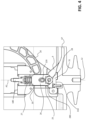
- the fixed arc contact member 17 is preferably formed by an elongated piece of conductive material having one end coupled to a first connecting member 170 (e.g. formed by a bolt), which is in turn coupled to the first main contact member 15, and an opposite free end (e.g. T-shaped) including a suitable contact surface with the movable arc contact member 18 ( figures 3 and 6 ).
- the fixed arc contact member 17 may be realized according to other solutions of known type (e.g. with a blade configuration), which are here not described in details for the sake of brevity.
- the movable arc contact member 18 is coupled to the support enclosure 9 so as to rotate together with this latter about the rotation axis A1. However, the movable arc contact member 18 is movable with respect to the enclosure 9 and the fixed arc contact member 17 along a translation axis (which is preferably the longitudinal axis A2) perpendicular to the rotation axis A1 of the movable contact assembly 10.
- the arc contact member 18 can be coupled to or uncoupled from the arc fixed contact member 17 by moving along the translation axis A2.
- the movable arc contact member 18 is coupled to the second main contact member 16.
- the movable arc contact member 18 is preferably formed by a shaped piece of conductive material having one end coupled to a second connecting member 180 and an opposite free end (e.g. T-shaped) including a suitable contact surface with the fixed arc contact member 17.
- the connecting member 180 is coupled to each blade of the second main contact member 16 and a first connecting pin 220 couples the blades of the second main contact member 16. In this way, the movable arc contact member 18 can move together with each blade along the translation axis A2 while rotating together with the movable contact assembly 10 about the rotation axis A1 ( figures 4 and 7 ).
- the connecting member 180 is preferably formed by a shaped piece of conductive material having a portion formed by a bolt coupled to the movable arc contact member 18 and another portion including a pair of parallel blades arranged in parallel to the blades of the second main contact member 16.
- the movable arc contact member 18 may be realized according to other solutions of known type (e.g. according to a configuration), which are here not described in details for the sake of brevity.
- the arc contact members 17, 18 are accommodated in the vacuum chamber 14, so that their contact surfaces are mutually coupled or decoupled inside said vacuum chamber, therefore being permanently immersed in a vacuum atmosphere.
- the switching apparatus 1 can switch from a closed state to an earthed state by carrying out an opening manoeuvre and subsequently a disconnecting manoeuvre.
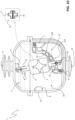
- the movable contact assembly 10 passes through an intermediate position P B , which corresponds to an open state of the switching apparatus, when it moves between the first and second end-of-run positions P A , Pc ( figures 8-16 ).
- the first main contact member 15 is decoupled from the first fixed contact member 5 and coupled to the fourth fixed contact member 8
- the second main contact member 16 is decoupled from the second fixed contact member 6 and coupled to the third fixed contact member 7
- the movable arc contact member 18 is coupled to the fixed arc contact member 17.
- This solution allows remarkably improving the overall dielectric behaviour of the switching apparatus since it prevents or reduces the arising of partial discharge phenomena in the internal volume of the switching apparatus, which may frequently occur due to parasitic capacitances, when the switching apparatus is an open state.
- each electric pole 2 comprises at least a track member 20 made of electrically insulating material and having a track surface 21 with a cam profile and at least a drive member 22 solidly coupled with the movable arc contact member 18 and slidingly coupled to the track surface 21 of a corresponding track member 20.
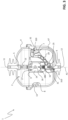
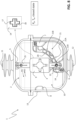
- each electric pole 2 comprises a track member 20 and a corresponding drive member 22 for each blade of the second main contact member 16 ( figures 2 and 5 ).
- each electric pole 2 comprises a pair of track members 20 and a corresponding pair of drive members 22, each slidingly coupled to the track surface 21 of a corresponding track member 20.
- Each track member 20 may be fixed to the insulating housing 4 or be integral part of this latter. In the embodiments shown in the cited figures, each track member 20 extends between the second fixed contact member 6 and the third fixed contact member 7, conveniently with a curved shape.
- each track member 20 is arranged at an outer edge of this latter, which faces the walls of the insulating housing 4 where the second and third fixed contact members 6, 7 are located.
- each drive member 22 is formed by a roller arranged in such a way to run along the track surface 21 of a corresponding track member 20.
- each drive member 22 is slidingly coupled to the second main contact member 16.
- each drive member 22 is arranged externally to a corresponding blade of the second main contact member 16 and it is coupled to the movable arc contact member 18 by means of the above-mentioned connecting pin 220 and connecting member 180.
- each drive member 22 with a corresponding track surface 21 of the track member 20 is ensured by a coupling force generated by the negative pressure constantly exerted on the movable arc contact member 18 (and directed to move this latter towards the fixed arc contact member 17) as the movable arc contact member 18 is accommodated in the vacuum chamber 14.
- the permanent contact of the drive member 22 with the track surface 21 may be ensured also in different additional ways, for example by suitably arranging a confined tracking slot in which the drive member 22 can slide.
- each drive member 22 slides along the track surface 21 of a corresponding track member 20, upon a rotational movement of the movable contact assembly 10 (and consequently of the movable arc contact 18) about the rotation axis A1.
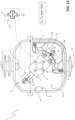
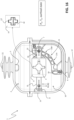
- the drive member 22 when the movable contact assembly 10 is in the first end-of run position P A , the drive member 22 is in a first position T A along the track surface 21 ( figure 8 ), when the movable contact assembly 10 is in the intermediate position P B , the drive member 22 is in a second position T B along the track surface 21 ( figure 12 ), and when the movable contact assembly 10 is in the second end-of run position P C , the drive member 22 is in a third position T C along the track surface 21 ( figure 16 ).
- the second position T B is obviously intermediate between the first and third positions T A , Tc.
- the first position T A is conveniently located at the second fixed contact member 6
- the third position Tc is located at the third fixed contact member 7
- the second position T B is substantially equally spaced from the first and third positions T A , Tc.
- each drive member 22 actuates the movable arc contact member 18 along the translation axis A2 between a coupled position to fixed arc contact member 17 and an uncoupled position from said fixed arc contact member, as said track surface has a cam profile.
- the track surface 21 is shaped so that the movable arc contact member 18 is actuated in a coupled position to the fixed arc contact member 17, when the drive member 22 is in the first position T A or in the second position T B or in the third position Tc along the track surface 21.
- each drive member 22 When sliding along the first track surface portion 21A, each drive member 22 actuates the movable arc contact member 18 along the longitudinal axis A2 between a coupled position to and an uncoupled position from the fixed arc contact member 17.
- the first track surface portion 21A is shaped so that the movable arc contact member 18 is decoupled from the fixed arc contact member 17 and it is subsequently coupled again with the fixed arc contact member 17, when the drive member 22 slides along said first track surface portion.
- the first track surface portion 21A conveniently includes first and second surface segments curved towards the fixed arc contact member 17 respectively in proximity of the first and second positions T A , T B and a second surface segment curved away from the fixed arc contact member 17 between said first and second surface segments.
- each drive member 22 When sliding along the second track surface portion 21B, each drive member 22 actuates the movable arc contact member 18 along the longitudinal axis A2 between a coupled position to and an uncoupled position from the fixed arc contact member 17.
- the movable contact assembly 10 of each electric pole 2 comprises a cam mechanism 25 coupled to the movable arc contact member 18.
- the cam mechanism 25 is conveniently adapted to press the movable arc contact member 18 against the fixed arc contact member 17, when the movable arc contact member 18 is coupled to the fixed arc contact member 17 and the movable contact assembly 10 is in the first end-of-run position P A or in the second end-of-run position Pc.
- the cam mechanism 25 comprises a push member 26, which is movable with respect to the movable contact member 18 (and to each blade of the of the second main contact member 16) along the translation axis A2 and a spring member 27 coupled to the push member 26 and to the movable arc contact member 18, more particularly to the above-mentioned connecting member 180.
- the push member 26 is formed by a sleeve arranged coaxially with the connecting member 180 along the longitudinal axis A2.
- the spring member 27 is preferably formed by a compression spring arranged along the longitudinal axis A2 and having an end coupled to a coupling surface of the connecting member 180 and the opposite end coupled to a coupling surface of the push member 26.
- the cam mechanism 25 comprises a slider member 28 coupled to the push member 26.
- the slider member 28 is couplable with one or more first cam surfaces 31 or with one or more second cam surfaces 32 when the movable contact assembly 10 is in the first end-of-run position P A or in the second end-of-run position Pc, respectively.
- the slider member 28 When it is coupled to the one or more first cam surfaces 31 or the one or more second cam surfaces 32, the slider member 28 exerts on the push member 26 an actuation force, which is directed to cause the compression of the spring member 27 and the consequent pressing of the movable arc contact member 18 against the fixed arc contact member 17.
- the slider member 28 is formed by a roller rotatably coupled to a second connecting pin 280, which is, in turn, solidly coupled to the push member 26 ( figure 4 ).
- the slider member 28 is conveniently positioned in the gap between the parallel blades of the second main contact member 6 and it can move with respect to these latter along the translation axis A2.
- a first jig member 310 may be fixed to the second fixed contact member 6, conveniently between the parallel blades of this latter.
- the first jig member 310 may be realized in one piece with the second fixed contact member 6.
- first and second cam surfaces 31, 32 may be part of jig members solidly coupled to or integrally made with the insulating housing 4.
- each electric pole 2 is in the operating condition illustrated in figure 12 .
- each electric pole 2 is in the operating condition illustrated in figure 16 .
- the switching apparatus 1 carries out an opening manoeuvre, when it switches from the closed state to the open state.
- each electric pole 2 is therefore in the operating condition of figure 8 .
- each movable contact assembly 10 moves, according to the first rotation direction R1, between the first end-of-run position P A and the intermediate position P B .
- the first main contact member 15 moves away from the first fixed contact member 5 while the second main contact member 16 moves away from the second fixed contact member 6.
- the movable arc contact member 18 progressively couples to the fixed arc contact member 17 while the first and second main contact members 15, 16 are already coupled to the first and second fixed contact members 5, 6.
- the switching apparatus 1 is now in a closed state.
- the switching apparatus 1 carries out a disconnecting manoeuvre, when it switches from an open state to an earthed state.
- the switching apparatus Before carrying out a disconnecting manoeuvre, the switching apparatus has to carry out an opening manoeuvre as described above in order to switch in an open state.
- each electric pole 2 is therefore in the operating condition of figure 12 .
- each movable contact assembly 10 moves, according to the first rotation direction R1, between the intermediate position P B and the second end-of-run position Pc.
- the first main contact member 15 moves towards the fourth fixed contact member 8 while the second main contact member 16 moves towards the third fixed contact member 7.
- the guiding member 22 moves away from the second position T B towards the third position Tc by sliding along the second track surface portion 21B (in particular along the fourth segment of this latter).
- the movable arc contact member 18 progressively decouples from the fixed arc contact member 17 ( figure 13 ).
- the guiding member 22 Upon a further movement of the movable contact assembly 10, the guiding member 22 keeps on sliding along the second track surface portion 21B (in particular along the sixth segment of this latter) thereby moving towards the third position Tc ( figure 14 ).
- the movable arc contact member 18 is decoupled from the fixed arc contact member 17 while the first and second main contact members 15, 16 progressively couple to the fourth and third fixed contact members 8, 7, respectively.
- the guiding member 22 keeps on sliding along the second track surface portion 21B (in particular along the fifth segment of this latter), thereby moving towards the third position Tc ( figure 15 ).
- the movable arc contact member 18 progressively couples to the fixed arc contact member 17 while the first and second main contact members 15, 16 are already coupled to the fourth and third fixed contact members 8, 7, respectively.
- the lever member 29 is fully coupled to the second sliding surfaces 34.
- the switching apparatus 1 is now in an earthed state.
- the switching apparatus 1 carries out a reconnecting manoeuvre, when it switches from an earthed state to an open state.
- each electric pole 2 is therefore in the operating condition of figure 16 .
- each movable contact assembly 10 moves, according to the second rotation direction R2, between the second end-of-run position P C and the intermediate position P B .
- the first main contact member 15 moves away from the fourth fixed contact member 8 while the second main contact member 16 moves away from the third fixed contact member 7.
- the slider member 28 progressively decouples from the second cam surfaces 32.
- the guiding member 22 starts moving away from the third position Tc towards the second position T B by sliding along the second track surface portion 21B.
- the guiding member 22 keeps on sliding along the second track surface portion 21B (in particular along the fifth and sixth segments of this latter) thereby moving towards the second position T B ( figure 14 ).
- the movable arc contact member 18 progressively decouples from the fixed arc contact member 17.
- the cam lever 29 (or the slider member 28) is decoupled from the second sliding surfaces 34 (or the second cam surfaces 32).
- the cam mechanism 25 does not operate anymore and the spring member 27 is released.
- the guiding member 22 keeps on sliding along the second track surface portion 21B (in particular along the fifth segment of this latter) thereby moving towards the second position T B ( figure 13 ).
- the movable arc contact member 18 is decoupled from the fixed arc contact member 17 and the first and second main contact members 15, 16 are decoupled from the first and second fixed contact members 5, 6.
- the guiding member 22 Upon a further movement of the movable contact assembly 10, the guiding member 22 keeps on sliding along the second track surface portion 21B (in particular along the fourth segment of this latter). The guiding member 22 reaches the second position T B when the movable contact assembly 10 reaches the intermediate position P B ( figure 12 ).
- the movable arc contact member 18 couples again to the fixed arc contact member 17 while the first and second main contact members 15, 16 remain decoupled from the first and second fixed contact members 5, 6.
- the switching apparatus 1 is now in an open state.
- the switching apparatus provides remarkable advantages with respect to the known apparatuses of the state of the art.
- the electric contacts 17, 18 accommodated within the vacuum chamber 14 of each electric pole are transitionally decoupled during the manoeuvres of the switching apparatus but remain mutually coupled when the switching apparatus is in a closed state, an open state or an earthed state. This allows improving the dielectric behaviour of the internal components of the switching apparatus, in particular when this latter is in an open state.
- the separation between the electric contacts 17, 18 accommodated within the vacuum chamber 14 is driven depending on the position reached by the main contact members 15, 16 during an opening manoeuvre of the switching apparatus.
- the breaking process of the current flowing along each electric pole is thus made to occur at level of the electric contacts 17, 18.
- Possible electric arcs deriving from the interruption of a current flowing along each electric pole therefore form in a vacuum atmosphere only, which allows improving their quenching.
- the switching apparatus of the invention has electric poles with a very compact, simple and robust structure with relevant benefits in terms of size optimization.
- the switching apparatus ensures high-level performances in terms of dielectric insulation and arc-quenching capabilities during the current breaking process and, at the same time, it is characterised by high levels of reliability for the intended applications.
- the switching apparatus is of relatively easy and cheap industrial production and installation on the field.
Landscapes
- Arc-Extinguishing Devices That Are Switches (AREA)
- High-Tension Arc-Extinguishing Switches Without Spraying Means (AREA)
- Rotary Switch, Piano Key Switch, And Lever Switch (AREA)
Claims (6)
- Schalteinrichtung (1) für elektrische Mittelspannungssysteme, wobei die Schalteinrichtung einen oder mehrere elektrische Pole (2) umfasst,wobei die Schalteinrichtung für jeden elektrischen Pol Folgendes umfasst:- einen ersten Polanschluss (11), einen zweiten Polanschluss (12) und einen Masseanschluss (13), wobei der erste Polanschluss (11) mit einem ersten Leiter einer elektrischen Leitung elektrisch koppelbar ist, der zweite Polanschluss (12) mit einem zweiten Leiter der elektrischen Leitung elektrisch koppelbar ist und der Masseanschluss (13) mit einem Erdungsleiter elektrisch koppelbar ist;- eine feste Kontaktanordnung, die mehrere feste Kontaktelemente umfasst, die voneinander beabstandet sind,wobei die feste Kontaktanordnung ein erstes festes Kontaktelement (5), das elektrisch mit dem ersten Polanschluss (11) verbunden ist, ein zweites festes Kontaktelement (6), das elektrisch mit dem zweiten Polanschluss (12) verbunden ist, ein drittes festes Kontaktelement (7) und ein viertes festes Kontaktelement (8), das elektrisch mit dem Masseanschluss (13) verbunden ist, umfasst;- eine bewegliche Kontaktanordnung (10), die um eine Drehachse (A1) drehbar ist und Folgendes umfasst:- ein erstes Hauptkontaktelement (15), das bei einer Drehbewegung der beweglichen Kontaktanordnung um die Drehachse (A1) mit dem ersten festen Kontaktelement (5) oder dem vierten festen Kontaktelement (8) koppelbar ist;- ein zweites Hauptkontaktelement (16), das bei einer Drehbewegung der beweglichen Kontaktanordnung um die Drehachse (A1) mit dem zweiten festen Kontaktelement (6) oder dem dritten festen Kontaktelement (7) koppelbar ist;- eine Vakuumkammer (14) und ein Paar Lichtbogenkontaktelemente (17, 18), die innerhalb der Vakuumkammer untergebracht sind und die miteinander gekoppelt oder voneinander entkoppelt werden können, wobei jedes Lichtbogenkontaktelement in Reihe mit einem entsprechenden Hauptkontaktelement (15, 16) elektrisch verbunden ist,wobei die Lichtbogenkontaktelemente (17, 18) ein festes Lichtbogenkontaktelement (17) und ein bewegliches Lichtbogenkontaktelement (18) umfassen,wobei das bewegliche Lichtbogenkontaktelement (18) durch Bewegen entlang einer Translationsachse (A2) senkrecht zu der Drehachse (A1) mit dem festen Lichtbogenkontaktelement (17) gekoppelt oder von diesem entkoppelt werden kann;wobei die bewegliche Kontaktanordnung reversibel um die Drehachse (A1) in eine erste Endlagenposition (PA),die einem geschlossenen Zustand der Schalteinrichtung entspricht, in eine zweite Endlagenposition (PC), die einem geerdeten Zustand der Schalteinrichtung entspricht, und in eine Zwischenposition (PB), die einem offenen Zustand der Schalteinrichtung entspricht, an der der erste und der zweite Polanschluss (11, 12) und der Masseanschluss (13) elektrisch voneinander getrennt sind, beweglich ist; wobei, wenn sich die bewegliche Kontaktanordnung (10) in der ersten Endlagenposition (PA) befindet, die Lichtbogenkontaktelemente (17, 18) miteinander gekoppelt sind,wobei die Schalteinrichtung für jeden elektrischen Pol mindestens ein Schienenelement (20), das aus elektrisch isolierendem Material besteht und eine Schienenoberfläche (21) mit einem Nockenprofil aufweist, und mindestens ein Antriebselement (22), das fest mit dem beweglichen Lichtbogenkontaktelement (18) gekoppelt ist, umfasst,wobei jedes Antriebselement (22) dazu ausgelegt ist, bei einer Drehbewegung der beweglichen Kontaktanordnung (10) um die Drehachse (A1) entlang der Schienenoberfläche (21) eines entsprechenden Schienenelements (20) zu gleiten,wobei das Antriebselement (22) das bewegliche Lichtbogenkontaktelement (18) entlang der Translationsachse (A2) zwischen einer an dem festen Lichtbogenkontaktelement (17) gekoppelten Position und einer davon entkoppelten Position betätigt, wenn es entlang der Schienenoberfläche (21) gleitet,wobei, wenn sich die bewegliche Kontaktanordnung (10) in der ersten Endlagenposition (PA) befindet, sich das Antriebselement (22) in einer ersten Position (TA) entlang der Schienenoberfläche (21) befindet,wobei, wenn sich die bewegliche Kontaktanordnung (10) in der Zwischenposition (PB) befindet, sich das Antriebselement (22) in einer zweiten Position (TB) entlang der Schienenoberfläche (21) befindet;wobei, wenn sich die bewegliche Kontaktanordnung (10) in der zweiten Endlagenposition (PC) befindet, sich das Antriebselement (22) in einer dritten Position (TC) entlang der Schienenoberfläche (21) befindet;wobei sich die zweite Position (TB) zwischenliegend zwischen der ersten und der dritten Position befindet, wobei das Antriebselement (22) entlang eines ersten Schienenoberflächenabschnitts (21A) mit einem Nockenprofil gleitet, wenn es sich zwischen der ersten und der zweiten Position (TA, TB) bewegt, und entlang eines zweiten Schienenoberflächenabschnitts (21B) mit einem Nockenprofil gleitet, wenn es sich zwischen der zweiten und der dritten Position (TB, TC) bewegt,wobei, wenn sich die bewegliche Kontaktanordnung (10) in der zweiten Endlagenposition (PC) befindet, das erste Hauptkontaktelement (15) mit dem vierten festen Kontaktelement (8) gekoppelt ist, das zweite Hauptkontaktelement (16) mit dem dritten festen Kontaktelement (7) gekoppelt ist und die Lichtbogenkontaktelemente (17, 18) miteinander gekoppelt sind,wobei, wenn sich die bewegliche Kontaktanordnung (10) in der Zwischenposition (PB) befindet, das erste Hauptkontaktelement (15) von dem ersten und dem vierten festen Kontaktelement (5, 8) entkoppelt ist und das zweite Hauptkontaktelement (16) von dem zweiten und dem dritten festen Kontaktelement (7) entkoppelt ist, dadurch gekennzeichnet, dass das dritte feste Kontaktelement (7) elektrisch mit dem zweiten Polanschluss verbunden ist,wobei, wenn sich die bewegliche Kontaktanordnung in der ersten Endlagenposition (PA) befindet, das erste Hauptkontaktelement (15) mit dem ersten festen Kontaktelement (5) gekoppelt ist und das zweite Hauptkontaktelement (16) mit dem zweiten festen Kontaktelement (6) gekoppelt ist,wobei, wenn sich die bewegliche Kontaktanordnung in der Zwischenposition (PB) befindet, die Lichtbogenkontaktelemente (17, 18) miteinander gekoppelt sind,wobei die Schienenoberfläche (21) so geformt ist, dass das bewegliche Lichtbogenkontaktelement (18) in eine mit dem festen Lichtbogenkontaktelement (17) gekoppelte Position betätigt wird, wenn sich das Antriebselement (22) in einer der ersten, zweiten und dritten Position (TA, TB, TC) entlang der Schienenoberfläche (21) befindet, wobei die Schienenoberfläche (21) so geformt ist, dass das Antriebselement (22) das bewegliche Lichtbogenkontaktelement (18) entlang der Translationsachse (A2) zwischen einer mit dem festen Lichtbogenkontaktelement (17) gekoppelten Position und einer davon entkoppelten Position betätigt, wenn es entlang des ersten Schienenoberflächenabschnitts (21A) oder des zweiten Schienenoberflächenabschnitts (21B) gleitet,wobei das bewegliche Lichtbogenkontaktelement (18) von dem festen Lichtbogenkontaktelement (17) entkoppelt und anschließend wieder mit dem festen Lichtbogenkontaktelement (17) gekoppelt wird, wenn das Antriebselement (22) entlang des ersten Schienenoberflächenabschnitts (21A) gleitet,wobei das bewegliche Lichtbogenkontaktelement (18) von dem festen Lichtbogenkontaktelement (17) entkoppelt und anschließend wieder mit dem festen Lichtbogenkontaktelement (17) gekoppelt wird, wenn das Antriebselement (22) entlang des zweiten Schienenoberflächenabschnitts (21B) gleitet.
- Schalteinrichtung nach Anspruch 1, dadurch gekennzeichnet, dass die bewegliche Kontaktanordnung (10) einen Nockenmechanismus (25) umfasst, der mit dem beweglichen Lichtbogenkontaktelement (18) gekoppelt ist,
wobei der Nockenmechanismus dazu ausgelegt ist, das bewegliche Lichtbogenkontaktelement (18) gegen das feste Lichtbogenkontaktelement (17) zu drücken, wenn das bewegliche Lichtbogenkontaktelement (18) mit dem festen Lichtbogenkontaktelement (17) gekoppelt ist und sich die bewegliche Kontaktanordnung (10) in der ersten Endlagenposition (PA) oder in der zweiten Endlagenposition (PB) befindet. - Schalteinrichtung nach Anspruch 2, dadurch gekennzeichnet, dass der Nockenmechanismus (25) Folgendes umfasst:- ein Schubelement (26), das in Bezug auf das bewegliche Lichtbogenkontaktelement (18) entlang der Translationsachse (A2) beweglich ist;- ein Federelement (27), das entlang der Translationsachse (A2) angeordnet und mit dem Schubelement (26) und dem beweglichen Lichtbogenkontaktelement (18) gekoppelt ist.
- Schalteinrichtung nach Anspruch 3, dadurch gekennzeichnet, dass der Nockenmechanismus (25) ein Schieberelement (28) umfasst, das mit dem Schubelement (26) gekoppelt und mit einer oder mehreren ersten Nockenflächen (31) oder einer oder mehreren zweiten Nockenflächen (32) koppelbar ist, wenn sich die bewegliche Kontaktanordnung (10) in der ersten Endlagenposition (PA) oder in der zweiten Endlagenposition (PC) befindet,
wobei das Schieberelement (28) eine Betätigungskraft auf das Schubelement (26) ausübt, die so gerichtet ist, dass sie das Zusammendrücken des Federelements (27) und das anschließende Drücken des beweglichen Lichtbogenkontaktelements (18) gegen das feste Lichtbogenkontaktelement (17) bewirkt, wenn es mit der einen oder den mehreren ersten Nockenflächen (31) oder der einen oder den mehreren zweiten Nockenflächen (32) gekoppelt ist. - Schalteinrichtung nach Anspruch 3, dadurch gekennzeichnet, dass der Nockenmechanismus (25) ein Hebelelement (29) umfasst, das ein Nockenprofil aufweist und mit dem Schubelement (26) und einer oder mehreren ersten Gleitflächen (33) oder einer oder mehreren zweiten Gleitflächen (34) koppelbar ist, wenn sich die bewegliche Kontaktanordnung (10) in der ersten Endlagenposition (PA) oder in der zweiten Endlagenposition (PC) befindet,
wobei das Hebelelement (29) eine Betätigungskraft auf das Schubelement (26) ausübt, die so gerichtet ist, dass sie das Zusammendrücken des Federelements (27) und das anschließende Drücken des beweglichen Lichtbogenkontaktelements (18) gegen das feste Lichtbogenkontaktelement (17) bewirkt, wenn es mit der einen oder den mehreren ersten Gleitflächen (33) oder der einen oder den mehreren zweiten Gleitflächen (34) gekoppelt ist. - Schalteinrichtung nach einem der vorhergehenden Ansprüche, dadurch gekennzeichnet, dass sie ein Lasttrennschalter für elektrische Mittelspannungssysteme ist.
Priority Applications (3)
| Application Number | Priority Date | Filing Date | Title |
|---|---|---|---|
| EP21173739.0A EP4089704B1 (de) | 2021-05-13 | 2021-05-13 | Mittelspannungsschaltvorrichtung |
| ES21173739T ES3035565T3 (en) | 2021-05-13 | 2021-05-13 | A medium voltage switching apparatus |
| CN202210515537.6A CN115346825A (zh) | 2021-05-13 | 2022-05-11 | 中压开关装置 |
Applications Claiming Priority (1)
| Application Number | Priority Date | Filing Date | Title |
|---|---|---|---|
| EP21173739.0A EP4089704B1 (de) | 2021-05-13 | 2021-05-13 | Mittelspannungsschaltvorrichtung |
Publications (2)
| Publication Number | Publication Date |
|---|---|
| EP4089704A1 EP4089704A1 (de) | 2022-11-16 |
| EP4089704B1 true EP4089704B1 (de) | 2025-04-09 |
Family
ID=75919241
Family Applications (1)
| Application Number | Title | Priority Date | Filing Date |
|---|---|---|---|
| EP21173739.0A Active EP4089704B1 (de) | 2021-05-13 | 2021-05-13 | Mittelspannungsschaltvorrichtung |
Country Status (3)
| Country | Link |
|---|---|
| EP (1) | EP4089704B1 (de) |
| CN (1) | CN115346825A (de) |
| ES (1) | ES3035565T3 (de) |
Family Cites Families (3)
| Publication number | Priority date | Publication date | Assignee | Title |
|---|---|---|---|---|
| DE2818914A1 (de) * | 1978-04-28 | 1979-10-31 | Siemens Ag | Schalterkombination fuer sammelschienenanlagen |
| DE102010045233B4 (de) * | 2010-09-10 | 2012-05-24 | Siemens Aktiengesellschaft | Lasttrennschalter |
| DE102011087630B4 (de) * | 2011-12-02 | 2016-11-03 | Siemens Aktiengesellschaft | Schaltgerät |
-
2021
- 2021-05-13 ES ES21173739T patent/ES3035565T3/es active Active
- 2021-05-13 EP EP21173739.0A patent/EP4089704B1/de active Active
-
2022
- 2022-05-11 CN CN202210515537.6A patent/CN115346825A/zh active Pending
Also Published As
| Publication number | Publication date |
|---|---|
| ES3035565T3 (en) | 2025-09-04 |
| CN115346825A (zh) | 2022-11-15 |
| EP4089704A1 (de) | 2022-11-16 |
Similar Documents
| Publication | Publication Date | Title |
|---|---|---|
| US11715613B2 (en) | Medium voltage switching apparatus | |
| US11776779B2 (en) | Medium voltage switching apparatus | |
| US12444559B2 (en) | Medium voltage switching apparatus | |
| US12387890B2 (en) | Medium voltage switching apparatus | |
| EP4089704B1 (de) | Mittelspannungsschaltvorrichtung | |
| EP4276872A1 (de) | Mittelspannungsschaltvorrichtung | |
| EP4089705A1 (de) | Mittelspannungsschaltvorrichtung | |
| EP4283645B1 (de) | Mittelspannungsschaltvorrichtung | |
| EP3093866B1 (de) | Elektrische poleinheit für gasisolierte mittelspannungs-schutzschalter | |
| US12293888B2 (en) | Medium voltage switching apparatus | |
| US20250372324A1 (en) | Medium voltage switching apparatus | |
| EP4276869A1 (de) | Mittelspannungsschaltvorrichtung | |
| EP4435815A1 (de) | Schaltvorrichtung für elektrische mittelspannungssysteme | |
| EP4030455A1 (de) | Mittelspannungsschaltvorrichtung | |
| EP4459653B1 (de) | Schaltvorrichtung für elektrische systeme | |
| JP4693736B2 (ja) | ガス絶縁断路器 | |
| CN120833986A (zh) | 用于电气系统的开关设备 |
Legal Events
| Date | Code | Title | Description |
|---|---|---|---|
| PUAI | Public reference made under article 153(3) epc to a published international application that has entered the european phase |
Free format text: ORIGINAL CODE: 0009012 |
|
| STAA | Information on the status of an ep patent application or granted ep patent |
Free format text: STATUS: THE APPLICATION HAS BEEN PUBLISHED |
|
| AK | Designated contracting states |
Kind code of ref document: A1 Designated state(s): AL AT BE BG CH CY CZ DE DK EE ES FI FR GB GR HR HU IE IS IT LI LT LU LV MC MK MT NL NO PL PT RO RS SE SI SK SM TR |
|
| STAA | Information on the status of an ep patent application or granted ep patent |
Free format text: STATUS: REQUEST FOR EXAMINATION WAS MADE |
|
| 17P | Request for examination filed |
Effective date: 20230505 |
|
| RBV | Designated contracting states (corrected) |
Designated state(s): AL AT BE BG CH CY CZ DE DK EE ES FI FR GB GR HR HU IE IS IT LI LT LU LV MC MK MT NL NO PL PT RO RS SE SI SK SM TR |
|
| GRAP | Despatch of communication of intention to grant a patent |
Free format text: ORIGINAL CODE: EPIDOSNIGR1 |
|
| STAA | Information on the status of an ep patent application or granted ep patent |
Free format text: STATUS: GRANT OF PATENT IS INTENDED |
|
| INTG | Intention to grant announced |
Effective date: 20241126 |
|
| GRAS | Grant fee paid |
Free format text: ORIGINAL CODE: EPIDOSNIGR3 |
|
| GRAA | (expected) grant |
Free format text: ORIGINAL CODE: 0009210 |
|
| STAA | Information on the status of an ep patent application or granted ep patent |
Free format text: STATUS: THE PATENT HAS BEEN GRANTED |
|
| AK | Designated contracting states |
Kind code of ref document: B1 Designated state(s): AL AT BE BG CH CY CZ DE DK EE ES FI FR GB GR HR HU IE IS IT LI LT LU LV MC MK MT NL NO PL PT RO RS SE SI SK SM TR |
|
| REG | Reference to a national code |
Ref country code: GB Ref legal event code: FG4D |
|
| REG | Reference to a national code |
Ref country code: CH Ref legal event code: EP |
|
| REG | Reference to a national code |
Ref country code: DE Ref legal event code: R096 Ref document number: 602021028770 Country of ref document: DE |
|
| REG | Reference to a national code |
Ref country code: IE Ref legal event code: FG4D |
|
| PGFP | Annual fee paid to national office [announced via postgrant information from national office to epo] |
Ref country code: DE Payment date: 20250521 Year of fee payment: 5 |
|
| PGFP | Annual fee paid to national office [announced via postgrant information from national office to epo] |
Ref country code: FR Payment date: 20250603 Year of fee payment: 5 |
|
| PGFP | Annual fee paid to national office [announced via postgrant information from national office to epo] |
Ref country code: AT Payment date: 20250721 Year of fee payment: 5 |
|
| REG | Reference to a national code |
Ref country code: NL Ref legal event code: MP Effective date: 20250409 |
|
| REG | Reference to a national code |
Ref country code: ES Ref legal event code: FG2A Ref document number: 3035565 Country of ref document: ES Kind code of ref document: T3 Effective date: 20250904 |
|
| PG25 | Lapsed in a contracting state [announced via postgrant information from national office to epo] |
Ref country code: NL Free format text: LAPSE BECAUSE OF FAILURE TO SUBMIT A TRANSLATION OF THE DESCRIPTION OR TO PAY THE FEE WITHIN THE PRESCRIBED TIME-LIMIT Effective date: 20250409 |
|
| REG | Reference to a national code |
Ref country code: AT Ref legal event code: MK05 Ref document number: 1784350 Country of ref document: AT Kind code of ref document: T Effective date: 20250409 |
|
| PG25 | Lapsed in a contracting state [announced via postgrant information from national office to epo] |
Ref country code: PT Free format text: LAPSE BECAUSE OF FAILURE TO SUBMIT A TRANSLATION OF THE DESCRIPTION OR TO PAY THE FEE WITHIN THE PRESCRIBED TIME-LIMIT Effective date: 20250811 Ref country code: FI Free format text: LAPSE BECAUSE OF FAILURE TO SUBMIT A TRANSLATION OF THE DESCRIPTION OR TO PAY THE FEE WITHIN THE PRESCRIBED TIME-LIMIT Effective date: 20250409 |
|
| PGFP | Annual fee paid to national office [announced via postgrant information from national office to epo] |
Ref country code: ES Payment date: 20250630 Year of fee payment: 5 |
|
| REG | Reference to a national code |
Ref country code: LT Ref legal event code: MG9D |
|
| PG25 | Lapsed in a contracting state [announced via postgrant information from national office to epo] |
Ref country code: GR Free format text: LAPSE BECAUSE OF FAILURE TO SUBMIT A TRANSLATION OF THE DESCRIPTION OR TO PAY THE FEE WITHIN THE PRESCRIBED TIME-LIMIT Effective date: 20250710 Ref country code: NO Free format text: LAPSE BECAUSE OF FAILURE TO SUBMIT A TRANSLATION OF THE DESCRIPTION OR TO PAY THE FEE WITHIN THE PRESCRIBED TIME-LIMIT Effective date: 20250709 |
|
| PG25 | Lapsed in a contracting state [announced via postgrant information from national office to epo] |
Ref country code: PL Free format text: LAPSE BECAUSE OF FAILURE TO SUBMIT A TRANSLATION OF THE DESCRIPTION OR TO PAY THE FEE WITHIN THE PRESCRIBED TIME-LIMIT Effective date: 20250409 |
|
| PGFP | Annual fee paid to national office [announced via postgrant information from national office to epo] |
Ref country code: IT Payment date: 20250730 Year of fee payment: 5 |
|
| PG25 | Lapsed in a contracting state [announced via postgrant information from national office to epo] |
Ref country code: BG Free format text: LAPSE BECAUSE OF FAILURE TO SUBMIT A TRANSLATION OF THE DESCRIPTION OR TO PAY THE FEE WITHIN THE PRESCRIBED TIME-LIMIT Effective date: 20250409 |
|
| PG25 | Lapsed in a contracting state [announced via postgrant information from national office to epo] |
Ref country code: HR Free format text: LAPSE BECAUSE OF FAILURE TO SUBMIT A TRANSLATION OF THE DESCRIPTION OR TO PAY THE FEE WITHIN THE PRESCRIBED TIME-LIMIT Effective date: 20250409 |
|
| PG25 | Lapsed in a contracting state [announced via postgrant information from national office to epo] |
Ref country code: AT Free format text: LAPSE BECAUSE OF FAILURE TO SUBMIT A TRANSLATION OF THE DESCRIPTION OR TO PAY THE FEE WITHIN THE PRESCRIBED TIME-LIMIT Effective date: 20250409 |
|
| PG25 | Lapsed in a contracting state [announced via postgrant information from national office to epo] |
Ref country code: RS Free format text: LAPSE BECAUSE OF FAILURE TO SUBMIT A TRANSLATION OF THE DESCRIPTION OR TO PAY THE FEE WITHIN THE PRESCRIBED TIME-LIMIT Effective date: 20250709 |
|
| PG25 | Lapsed in a contracting state [announced via postgrant information from national office to epo] |
Ref country code: IS Free format text: LAPSE BECAUSE OF FAILURE TO SUBMIT A TRANSLATION OF THE DESCRIPTION OR TO PAY THE FEE WITHIN THE PRESCRIBED TIME-LIMIT Effective date: 20250809 |
|
| PG25 | Lapsed in a contracting state [announced via postgrant information from national office to epo] |
Ref country code: LV Free format text: LAPSE BECAUSE OF FAILURE TO SUBMIT A TRANSLATION OF THE DESCRIPTION OR TO PAY THE FEE WITHIN THE PRESCRIBED TIME-LIMIT Effective date: 20250409 |