EP4299376B1 - Leuchtbakenanordnung - Google Patents
Leuchtbakenanordnung Download PDFInfo
- Publication number
- EP4299376B1 EP4299376B1 EP23182158.8A EP23182158A EP4299376B1 EP 4299376 B1 EP4299376 B1 EP 4299376B1 EP 23182158 A EP23182158 A EP 23182158A EP 4299376 B1 EP4299376 B1 EP 4299376B1
- Authority
- EP
- European Patent Office
- Prior art keywords
- beacon
- base
- housing
- suction cup
- luminous
- Prior art date
- Legal status (The legal status is an assumption and is not a legal conclusion. Google has not performed a legal analysis and makes no representation as to the accuracy of the status listed.)
- Active
Links
Images
Classifications
-
- B—PERFORMING OPERATIONS; TRANSPORTING
- B60—VEHICLES IN GENERAL
- B60Q—ARRANGEMENT OF SIGNALLING OR LIGHTING DEVICES, THE MOUNTING OR SUPPORTING THEREOF OR CIRCUITS THEREFOR, FOR VEHICLES IN GENERAL
- B60Q1/00—Arrangement of optical signalling or lighting devices, the mounting or supporting thereof or circuits therefor
- B60Q1/26—Arrangement of optical signalling or lighting devices, the mounting or supporting thereof or circuits therefor the devices being primarily intended to indicate the vehicle, or parts thereof, or to give signals, to other traffic
- B60Q1/2611—Indicating devices mounted on the roof of the vehicle
-
- B—PERFORMING OPERATIONS; TRANSPORTING
- B60—VEHICLES IN GENERAL
- B60Q—ARRANGEMENT OF SIGNALLING OR LIGHTING DEVICES, THE MOUNTING OR SUPPORTING THEREOF OR CIRCUITS THEREFOR, FOR VEHICLES IN GENERAL
- B60Q1/00—Arrangement of optical signalling or lighting devices, the mounting or supporting thereof or circuits therefor
- B60Q1/26—Arrangement of optical signalling or lighting devices, the mounting or supporting thereof or circuits therefor the devices being primarily intended to indicate the vehicle, or parts thereof, or to give signals, to other traffic
- B60Q1/2615—Arrangement of optical signalling or lighting devices, the mounting or supporting thereof or circuits therefor the devices being primarily intended to indicate the vehicle, or parts thereof, or to give signals, to other traffic mounted on the vehicle body, e.g. with magnets
-
- F—MECHANICAL ENGINEERING; LIGHTING; HEATING; WEAPONS; BLASTING
- F21—LIGHTING
- F21V—FUNCTIONAL FEATURES OR DETAILS OF LIGHTING DEVICES OR SYSTEMS THEREOF; STRUCTURAL COMBINATIONS OF LIGHTING DEVICES WITH OTHER ARTICLES, NOT OTHERWISE PROVIDED FOR
- F21V21/00—Supporting, suspending, or attaching arrangements for lighting devices; Hand grips
- F21V21/08—Devices for easy attachment to any desired place, e.g. clip, clamp, magnet
- F21V21/092—Suction devices
-
- F—MECHANICAL ENGINEERING; LIGHTING; HEATING; WEAPONS; BLASTING
- F16—ENGINEERING ELEMENTS AND UNITS; GENERAL MEASURES FOR PRODUCING AND MAINTAINING EFFECTIVE FUNCTIONING OF MACHINES OR INSTALLATIONS; THERMAL INSULATION IN GENERAL
- F16B—DEVICES FOR FASTENING OR SECURING CONSTRUCTIONAL ELEMENTS OR MACHINE PARTS TOGETHER, e.g. NAILS, BOLTS, CIRCLIPS, CLAMPS, CLIPS OR WEDGES; JOINTS OR JOINTING
- F16B47/00—Suction cups for attaching purposes; Equivalent means using adhesives
-
- F—MECHANICAL ENGINEERING; LIGHTING; HEATING; WEAPONS; BLASTING
- F21—LIGHTING
- F21W—INDEXING SCHEME ASSOCIATED WITH SUBCLASSES F21K, F21L, F21S and F21V, RELATING TO USES OR APPLICATIONS OF LIGHTING DEVICES OR SYSTEMS
- F21W2111/00—Use or application of lighting devices or systems for signalling, marking or indicating, not provided for in codes F21W2102/00 – F21W2107/00
Definitions
- the present invention can be included within the field of signalling, more specifically, light signalling by means of light. More specifically, the object of the invention relates to a luminous beacon assembly, which has a luminous beacon and a suction cup-type fastening.
- Luminous beacons intended, for example, to signal the presence of vehicles involved in accidents on a road are known.
- the beacons are stored inside the vehicle so that, in the event of an incident, they can be placed on the roof of said vehicle and luminously signal the presence of said vehicle, as well as warn of a traffic incident.
- Beacons of this type have a casing with magnetic properties so that they can be securely fastened to the roof of the signalled vehicle, and be subsequently removed when their function is no longer required.
- suction cup-based solutions are used, in which the casing of the beacon is fastened to several perimeter suction cups by means of screwed joints.
- the dimensions of the "beacon + suction cups" assembly increase substantially and, on the other hand, the use of screws and tools to fasten the suction cups to the beacon in the factory becomes necessary.
- the described configuration prevents a user from using the beacons for magnetic surfaces on other surfaces.
- WO 2015/054979 A1 discloses an arrangement combining the attractive force of a magnet and the force of a suction cup to firmly mount a beacon onto a vehicle body.
- the suction cup holder is also mounted to the beacon by screws.
- the present invention solves the aforementioned drawbacks by means of a luminous beacon assembly according to the main claim.
- Other optional advantageous embodiments are the object of the dependent claims.
- the luminous beacon assembly of the invention provides the possibility of fastening a luminous beacon to a non-magnetic (or non-magnetisable) surface which, in particular, makes it possible to recover luminous beacons initially marketed for use through magnetic fastening, all of this without substantially increasing storage space needs, in particular, the perimeter dimensions, and without requiring the use of tools to attach the beacon on a fastening by means of suction cup(s).
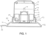
- Figure 1 represents an elevation sectional view of the beacon assembly of the invention.
- the luminous beacon assembly of the invention comprises a luminous beacon (10) and a suction cup-type fastening (20), intended to house the beacon (10), as explained below.
- the beacon (10) has a casing (11), with a bottom base (12) and a top portion (13), wherein the casing (11) houses lighting means (14) and a battery (not shown), which powers the lighting means (14).
- the top portion (13) is transparent or translucent, to allow the light emitted by the lighting means (14) to be seen.
- the casing (11) can also house control means (not shown) to control the operation of the lighting means (14).
- the lighting means (14) may include one or more LEDs (not shown), controlled by the control means, to light up in one or more predetermined colours, for example, according to a predefined sequence.
- the top portion (13) of the casing (11) can be coloured, such as by zones; for example, with a first band (15) of orange or yellow, located between two second bands (16) of red.
- the base (12) of the casing (11), for its part, is preferably cylindrical, and even more preferably has a circular section. It can also have other types of sections, such as a polygonal section, defining a faceted beacon.
- the base (12) can be magnetised, to make it possible to incorporate in the present beacon assembly a beacon (10) initially configured to be fastened magnetically.
- the base (12) has a bevelled narrowing (17), which serves as a transition from the base (12) to the top portion (13).
- the beacon (10) can preferably include a positioning system (not shown), such as GPS, as well as a communication system (not shown), powered by the battery and controlled by the control means, to communicate with Emergency Services (Department of Traffic, police, etc.), broadcasting the position of the beacon (10).
- the communication system is preferably configured to communicate and broadcast autonomously, without relying on an external telephone or data line, such as those of a user's mobile phone.
- the suction cup (22) preferably protrudes transversely (seen in plan view) with respect to the housing (23).
- the suction cup (22) can include a tab (25), preferably on its perimeter portion, to lift upwards and break the vacuum.
Landscapes
- Engineering & Computer Science (AREA)
- Mechanical Engineering (AREA)
- General Engineering & Computer Science (AREA)
- Hooks, Suction Cups, And Attachment By Adhesive Means (AREA)
- Non-Portable Lighting Devices Or Systems Thereof (AREA)
- Road Signs Or Road Markings (AREA)
Claims (6)
- Leuchtbakenanordnung, dadurch gekennzeichnet, dass sie umfasst:- eine Leuchtbake (10), die ein Gehäuse (11) mit einem oberen Abschnitt (13) und einer unteren Basis (12) und mit einer abgeschrägten Verengung (17) von der Basis (12) zu dem oberen Abschnitt (13) einschließt; und- eine saugnapfartige Befestigung (20), die dazu bestimmt ist, die Bake (10) unterzubringen und zu halten, und die einen Befestigungskörper (21) mit einem Saugnapf (22) an seinem unteren Abschnitt umfasst, um die Befestigung (20) an einer gewünschten Oberfläche zu befestigen, wobei der Befestigungskörper (21) ferner ein oberes Gehäuse (23) an seinem oberen Abschnitt umfasst, um die Basis (12) aufzunehmen und zu halten;wobei das Gehäuse (23) eine Form aufweist, die der Basis (12) entspricht, und das Gehäuse (23) eine abgeschrägte Verengung (24) einschließt, die der Verengung (17) der Basis (12) entspricht;wobei das Gehäuse (23) aus einem verformbaren Material besteht, das ermöglicht, die Basis (12) der Bake (10) durch einen Formschluss zu halten, der ein Einschieben der Basis (12), die größer ist, durch die im Gehäuse (23) definierte Verengung (24) erzwingt.
- Leuchtbakenanordnung nach Anspruch 1, dadurch gekennzeichnet, dass der Befestigungskörper (21) monolithisch ist, wobei der Saugnapf (22) des unteren Abschnitts und das Gehäuse (23) des oberen Abschnitts in ein einen gleichen Körper integriert sind.
- Leuchtbakenanordnung nach einem der Ansprüche 1 bis 2, dadurch gekennzeichnet, dass der Saugnapf (22) und das Gehäuse (23) koaxial sowie koaxial zur Basis (12) der Leuchtbake (10) konfiguriert sind.
- Leuchtbakenanordnung nach einem der Ansprüche 1 bis 3, dadurch gekennzeichnet, dass die Basis (12) magnetisiert ist.
- Leuchtbakenanordnung nach einem der Ansprüche 1 bis 4, dadurch gekennzeichnet, dass der Saugnapf (22) quer, d. h. in der Draufsicht, in Bezug auf das Gehäuse (23) hervorsteht.
- Leuchtbakenanordnung nach einem der Ansprüche 1 bis 5, dadurch gekennzeichnet, dass der Saugnapf (22) zusätzlich eine Lasche (25) einschließt, um den Saugnapf (22) nach oben zu heben und von der gewünschten Oberfläche zu trennen.
Applications Claiming Priority (1)
| Application Number | Priority Date | Filing Date | Title |
|---|---|---|---|
| ES202231118U ES1294744Y (es) | 2022-07-01 | 2022-07-01 | Conjunto de baliza luminosa |
Publications (3)
| Publication Number | Publication Date |
|---|---|
| EP4299376A1 EP4299376A1 (de) | 2024-01-03 |
| EP4299376B1 true EP4299376B1 (de) | 2025-04-16 |
| EP4299376C0 EP4299376C0 (de) | 2025-04-16 |
Family
ID=83452880
Family Applications (1)
| Application Number | Title | Priority Date | Filing Date |
|---|---|---|---|
| EP23182158.8A Active EP4299376B1 (de) | 2022-07-01 | 2023-06-28 | Leuchtbakenanordnung |
Country Status (2)
| Country | Link |
|---|---|
| EP (1) | EP4299376B1 (de) |
| ES (2) | ES1294744Y (de) |
Family Cites Families (5)
| Publication number | Priority date | Publication date | Assignee | Title |
|---|---|---|---|---|
| US2963256A (en) * | 1957-09-23 | 1960-12-06 | John E Borah | Article retainer |
| DE1925461U (de) * | 1965-08-16 | 1965-10-14 | Paulheinz Fitterer | Blinkleuchte, insbesondere fuer kraftfahrzeuge. |
| DE8100216U1 (de) * | 1981-01-08 | 1981-07-23 | Schütz, Wolfgang, 5810 Witten | Zusatzbrems- oder rueckleuchte zum nachtraeglichen einbau in strassenfahrzeuge |
| WO2015054979A1 (zh) * | 2013-10-17 | 2015-04-23 | 宁波市鄞州赛艾富光电科技有限公司 | 警示灯灯组及包含该灯组的灯塔 |
| CN213896863U (zh) * | 2020-11-11 | 2021-08-06 | 于慧 | 一种电气施工用安全警示装置 |
-
2022
- 2022-07-01 ES ES202231118U patent/ES1294744Y/es active Active
-
2023
- 2023-06-28 ES ES23182158T patent/ES3035634T3/es active Active
- 2023-06-28 EP EP23182158.8A patent/EP4299376B1/de active Active
Also Published As
| Publication number | Publication date |
|---|---|
| ES1294744Y (es) | 2022-12-27 |
| EP4299376C0 (de) | 2025-04-16 |
| EP4299376A1 (de) | 2024-01-03 |
| ES1294744U (es) | 2022-10-05 |
| ES3035634T3 (en) | 2025-09-05 |
Similar Documents
| Publication | Publication Date | Title |
|---|---|---|
| US7369061B1 (en) | Vehicle locator device | |
| US8581744B2 (en) | Traffic information warning systems and methods | |
| US7905622B2 (en) | Traffic safety cone incorporating a flashing light module | |
| US20070171082A1 (en) | Flashlight with sos and energy saver features | |
| US6305819B1 (en) | Illuminating warning device | |
| CN212313411U (zh) | 一种智能安全警示灯运营系统及其智能安全警示灯终端 | |
| US20190021921A1 (en) | Wheelchair systems and related methods | |
| CN108430829A (zh) | 信号警示灯 | |
| US6407675B1 (en) | Traffic sign warning light and method therefor | |
| EP4299376A1 (de) | Leuchtbakenanordnung | |
| EP4389522A1 (de) | Beleuchtete vorrichtung zur anzeige einer notsituation | |
| GB2041430A (en) | A portable warning sign | |
| WO2018100513A1 (en) | Pedestrian and hazard alert system | |
| JP2002275839A (ja) | 内部発光保安用表示具 | |
| EP4545357A1 (de) | Positionierungsbake mit einteiliger basis | |
| WO2006038853A1 (en) | A system for indicating presence of a person im a road area | |
| US20040164861A1 (en) | Antenna-mounted vehicle location system | |
| US20120200227A1 (en) | Portable illuminated house and vehicle locating device | |
| US20030160690A1 (en) | Magnetically mountable vehicle hazard device | |
| CN105034942A (zh) | 一种警示装置 | |
| US20250265949A1 (en) | Multifunctional Stop-Sign Device | |
| US8963738B2 (en) | Vehicle information systems and methods | |
| GB2362020A (en) | Warning device to alert people to in-car use of a mobile phone | |
| CN215911149U (zh) | 交通警示灯 | |
| JP3097952B2 (ja) | 発光リングを備えたデリネ―タ― |
Legal Events
| Date | Code | Title | Description |
|---|---|---|---|
| PUAI | Public reference made under article 153(3) epc to a published international application that has entered the european phase |
Free format text: ORIGINAL CODE: 0009012 |
|
| STAA | Information on the status of an ep patent application or granted ep patent |
Free format text: STATUS: THE APPLICATION HAS BEEN PUBLISHED |
|
| AK | Designated contracting states |
Kind code of ref document: A1 Designated state(s): AL AT BE BG CH CY CZ DE DK EE ES FI FR GB GR HR HU IE IS IT LI LT LU LV MC ME MK MT NL NO PL PT RO RS SE SI SK SM TR |
|
| STAA | Information on the status of an ep patent application or granted ep patent |
Free format text: STATUS: REQUEST FOR EXAMINATION WAS MADE |
|
| 17P | Request for examination filed |
Effective date: 20240701 |
|
| RBV | Designated contracting states (corrected) |
Designated state(s): AL AT BE BG CH CY CZ DE DK EE ES FI FR GB GR HR HU IE IS IT LI LT LU LV MC ME MK MT NL NO PL PT RO RS SE SI SK SM TR |
|
| RIC1 | Information provided on ipc code assigned before grant |
Ipc: F21W 111/00 20060101ALI20240920BHEP Ipc: F21V 21/092 20060101ALI20240920BHEP Ipc: F16B 47/00 20060101ALI20240920BHEP Ipc: F21V 17/10 20060101ALI20240920BHEP Ipc: B60Q 1/26 20060101AFI20240920BHEP |
|
| GRAP | Despatch of communication of intention to grant a patent |
Free format text: ORIGINAL CODE: EPIDOSNIGR1 |
|
| STAA | Information on the status of an ep patent application or granted ep patent |
Free format text: STATUS: GRANT OF PATENT IS INTENDED |
|
| INTG | Intention to grant announced |
Effective date: 20241113 |
|
| GRAS | Grant fee paid |
Free format text: ORIGINAL CODE: EPIDOSNIGR3 |
|
| GRAA | (expected) grant |
Free format text: ORIGINAL CODE: 0009210 |
|
| STAA | Information on the status of an ep patent application or granted ep patent |
Free format text: STATUS: THE PATENT HAS BEEN GRANTED |
|
| AK | Designated contracting states |
Kind code of ref document: B1 Designated state(s): AL AT BE BG CH CY CZ DE DK EE ES FI FR GB GR HR HU IE IS IT LI LT LU LV MC ME MK MT NL NO PL PT RO RS SE SI SK SM TR |
|
| REG | Reference to a national code |
Ref country code: GB Ref legal event code: FG4D |
|
| REG | Reference to a national code |
Ref country code: CH Ref legal event code: EP Ref country code: DE Ref legal event code: R096 Ref document number: 602023002913 Country of ref document: DE |
|
| REG | Reference to a national code |
Ref country code: IE Ref legal event code: FG4D |
|
| U01 | Request for unitary effect filed |
Effective date: 20250515 |
|
| U07 | Unitary effect registered |
Designated state(s): AT BE BG DE DK EE FI FR IT LT LU LV MT NL PT RO SE SI Effective date: 20250521 |
|
| U20 | Renewal fee for the european patent with unitary effect paid |
Year of fee payment: 3 Effective date: 20250627 |
|
| REG | Reference to a national code |
Ref country code: ES Ref legal event code: FG2A Ref document number: 3035634 Country of ref document: ES Kind code of ref document: T3 Effective date: 20250905 |
|
| PGFP | Annual fee paid to national office [announced via postgrant information from national office to epo] |
Ref country code: ES Payment date: 20250714 Year of fee payment: 3 |
|
| PG25 | Lapsed in a contracting state [announced via postgrant information from national office to epo] |
Ref country code: NO Free format text: LAPSE BECAUSE OF FAILURE TO SUBMIT A TRANSLATION OF THE DESCRIPTION OR TO PAY THE FEE WITHIN THE PRESCRIBED TIME-LIMIT Effective date: 20250716 Ref country code: GR Free format text: LAPSE BECAUSE OF FAILURE TO SUBMIT A TRANSLATION OF THE DESCRIPTION OR TO PAY THE FEE WITHIN THE PRESCRIBED TIME-LIMIT Effective date: 20250717 |
|
| PG25 | Lapsed in a contracting state [announced via postgrant information from national office to epo] |
Ref country code: PL Free format text: LAPSE BECAUSE OF FAILURE TO SUBMIT A TRANSLATION OF THE DESCRIPTION OR TO PAY THE FEE WITHIN THE PRESCRIBED TIME-LIMIT Effective date: 20250416 |
|
| PG25 | Lapsed in a contracting state [announced via postgrant information from national office to epo] |
Ref country code: HR Free format text: LAPSE BECAUSE OF FAILURE TO SUBMIT A TRANSLATION OF THE DESCRIPTION OR TO PAY THE FEE WITHIN THE PRESCRIBED TIME-LIMIT Effective date: 20250416 |
|
| PG25 | Lapsed in a contracting state [announced via postgrant information from national office to epo] |
Ref country code: RS Free format text: LAPSE BECAUSE OF FAILURE TO SUBMIT A TRANSLATION OF THE DESCRIPTION OR TO PAY THE FEE WITHIN THE PRESCRIBED TIME-LIMIT Effective date: 20250716 |
|
| PGFP | Annual fee paid to national office [announced via postgrant information from national office to epo] |
Ref country code: IE Payment date: 20250718 Year of fee payment: 3 |
|
| PG25 | Lapsed in a contracting state [announced via postgrant information from national office to epo] |
Ref country code: IS Free format text: LAPSE BECAUSE OF FAILURE TO SUBMIT A TRANSLATION OF THE DESCRIPTION OR TO PAY THE FEE WITHIN THE PRESCRIBED TIME-LIMIT Effective date: 20250816 |
|
| PG25 | Lapsed in a contracting state [announced via postgrant information from national office to epo] |
Ref country code: SM Free format text: LAPSE BECAUSE OF FAILURE TO SUBMIT A TRANSLATION OF THE DESCRIPTION OR TO PAY THE FEE WITHIN THE PRESCRIBED TIME-LIMIT Effective date: 20250416 |
|
| PG25 | Lapsed in a contracting state [announced via postgrant information from national office to epo] |
Ref country code: CZ Free format text: LAPSE BECAUSE OF FAILURE TO SUBMIT A TRANSLATION OF THE DESCRIPTION OR TO PAY THE FEE WITHIN THE PRESCRIBED TIME-LIMIT Effective date: 20250416 |
|
| PG25 | Lapsed in a contracting state [announced via postgrant information from national office to epo] |
Ref country code: SK Free format text: LAPSE BECAUSE OF FAILURE TO SUBMIT A TRANSLATION OF THE DESCRIPTION OR TO PAY THE FEE WITHIN THE PRESCRIBED TIME-LIMIT Effective date: 20250416 |
|
| PG25 | Lapsed in a contracting state [announced via postgrant information from national office to epo] |
Ref country code: MC Free format text: LAPSE BECAUSE OF FAILURE TO SUBMIT A TRANSLATION OF THE DESCRIPTION OR TO PAY THE FEE WITHIN THE PRESCRIBED TIME-LIMIT Effective date: 20250416 |
|
| PLBE | No opposition filed within time limit |
Free format text: ORIGINAL CODE: 0009261 |
|
| STAA | Information on the status of an ep patent application or granted ep patent |
Free format text: STATUS: NO OPPOSITION FILED WITHIN TIME LIMIT |
|
| REG | Reference to a national code |
Ref country code: CH Ref legal event code: L10 Free format text: ST27 STATUS EVENT CODE: U-0-0-L10-L00 (AS PROVIDED BY THE NATIONAL OFFICE) Effective date: 20260225 |
|
| 26N | No opposition filed |
Effective date: 20260119 |