EP4298375B1 - Verfahren zur befestigung einer abschlussscheibe für einen kraftfahrzeugscheinwerfer an einem kraftfahrzeugscheinwerfergehäuse - Google Patents
Verfahren zur befestigung einer abschlussscheibe für einen kraftfahrzeugscheinwerfer an einem kraftfahrzeugscheinwerfergehäuse Download PDFInfo
- Publication number
- EP4298375B1 EP4298375B1 EP22700669.9A EP22700669A EP4298375B1 EP 4298375 B1 EP4298375 B1 EP 4298375B1 EP 22700669 A EP22700669 A EP 22700669A EP 4298375 B1 EP4298375 B1 EP 4298375B1
- Authority
- EP
- European Patent Office
- Prior art keywords
- motor vehicle
- light
- vehicle headlamp
- assembly
- cover lens
- Prior art date
- Legal status (The legal status is an assumption and is not a legal conclusion. Google has not performed a legal analysis and makes no representation as to the accuracy of the status listed.)
- Active
Links
Images
Classifications
-
- F—MECHANICAL ENGINEERING; LIGHTING; HEATING; WEAPONS; BLASTING
- F21—LIGHTING
- F21S—NON-PORTABLE LIGHTING DEVICES; SYSTEMS THEREOF; VEHICLE LIGHTING DEVICES SPECIALLY ADAPTED FOR VEHICLE EXTERIORS
- F21S41/00—Illuminating devices specially adapted for vehicle exteriors, e.g. headlamps
- F21S41/20—Illuminating devices specially adapted for vehicle exteriors, e.g. headlamps characterised by refractors, transparent cover plates, light guides or filters
- F21S41/29—Attachment thereof
- F21S41/295—Attachment thereof specially adapted to projection lenses
-
- F—MECHANICAL ENGINEERING; LIGHTING; HEATING; WEAPONS; BLASTING
- F21—LIGHTING
- F21S—NON-PORTABLE LIGHTING DEVICES; SYSTEMS THEREOF; VEHICLE LIGHTING DEVICES SPECIALLY ADAPTED FOR VEHICLE EXTERIORS
- F21S41/00—Illuminating devices specially adapted for vehicle exteriors, e.g. headlamps
- F21S41/20—Illuminating devices specially adapted for vehicle exteriors, e.g. headlamps characterised by refractors, transparent cover plates, light guides or filters
- F21S41/29—Attachment thereof
-
- F—MECHANICAL ENGINEERING; LIGHTING; HEATING; WEAPONS; BLASTING
- F21—LIGHTING
- F21S—NON-PORTABLE LIGHTING DEVICES; SYSTEMS THEREOF; VEHICLE LIGHTING DEVICES SPECIALLY ADAPTED FOR VEHICLE EXTERIORS
- F21S41/00—Illuminating devices specially adapted for vehicle exteriors, e.g. headlamps
- F21S41/10—Illuminating devices specially adapted for vehicle exteriors, e.g. headlamps characterised by the light source
- F21S41/14—Illuminating devices specially adapted for vehicle exteriors, e.g. headlamps characterised by the light source characterised by the type of light source
- F21S41/141—Light emitting diodes [LED]
- F21S41/147—Light emitting diodes [LED] the main emission direction of the LED being angled to the optical axis of the illuminating device
- F21S41/148—Light emitting diodes [LED] the main emission direction of the LED being angled to the optical axis of the illuminating device the main emission direction of the LED being perpendicular to the optical axis
-
- F—MECHANICAL ENGINEERING; LIGHTING; HEATING; WEAPONS; BLASTING
- F21—LIGHTING
- F21S—NON-PORTABLE LIGHTING DEVICES; SYSTEMS THEREOF; VEHICLE LIGHTING DEVICES SPECIALLY ADAPTED FOR VEHICLE EXTERIORS
- F21S41/00—Illuminating devices specially adapted for vehicle exteriors, e.g. headlamps
- F21S41/20—Illuminating devices specially adapted for vehicle exteriors, e.g. headlamps characterised by refractors, transparent cover plates, light guides or filters
- F21S41/28—Cover glass
-
- F—MECHANICAL ENGINEERING; LIGHTING; HEATING; WEAPONS; BLASTING
- F21—LIGHTING
- F21S—NON-PORTABLE LIGHTING DEVICES; SYSTEMS THEREOF; VEHICLE LIGHTING DEVICES SPECIALLY ADAPTED FOR VEHICLE EXTERIORS
- F21S41/00—Illuminating devices specially adapted for vehicle exteriors, e.g. headlamps
- F21S41/20—Illuminating devices specially adapted for vehicle exteriors, e.g. headlamps characterised by refractors, transparent cover plates, light guides or filters
- F21S41/2805—Cover glass
-
- F—MECHANICAL ENGINEERING; LIGHTING; HEATING; WEAPONS; BLASTING
- F21—LIGHTING
- F21S—NON-PORTABLE LIGHTING DEVICES; SYSTEMS THEREOF; VEHICLE LIGHTING DEVICES SPECIALLY ADAPTED FOR VEHICLE EXTERIORS
- F21S41/00—Illuminating devices specially adapted for vehicle exteriors, e.g. headlamps
- F21S41/40—Illuminating devices specially adapted for vehicle exteriors, e.g. headlamps characterised by screens, non-reflecting members, light-shielding members or fixed shades
- F21S41/47—Attachment thereof
-
- F—MECHANICAL ENGINEERING; LIGHTING; HEATING; WEAPONS; BLASTING
- F21—LIGHTING
- F21V—FUNCTIONAL FEATURES OR DETAILS OF LIGHTING DEVICES OR SYSTEMS THEREOF; STRUCTURAL COMBINATIONS OF LIGHTING DEVICES WITH OTHER ARTICLES, NOT OTHERWISE PROVIDED FOR
- F21V15/00—Protecting lighting devices from damage
- F21V15/01—Housings, e.g. material or assembling of housing parts
Definitions
- the invention relates to a method for fastening a cover lens for a motor vehicle headlight to a motor vehicle headlight housing.
- headlights which are intended to produce at least two light functions or light distributions are designed in such a way that, in the best case, a chamber which is at least optically closed is provided for each light function.
- step b) the transfer of the assembly into the assembly position in step b) and into the final position in step c) is carried out using adjusting screws.
- the adjusting screws are accessible from outside the vehicle headlight housing.
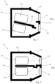
- Fig. 1 and Fig. 2 together show a method for fastening a cover lens 100 for a motor vehicle headlight 10 to a motor vehicle headlight housing 200 , wherein in a first step a) a motor vehicle headlight housing 200 is provided, wherein a first light module 210 , which contributes to generating a first light distribution, and a second light module 220 , which contributes to generating a second light distribution, are arranged in the motor vehicle headlight housing 200.
- a holding body is provided on which the first and second light modules 210 , 220 and the cover 230 are arranged, wherein the holding body, the first and second light modules 210 , 220 and the cover 230 form an assembly, and wherein the assembly can be brought into an assembly position P1 and into an end position P2 deviating from the assembly position P1 in the motor vehicle headlight housing 200 .
- a cover plate 100 which has a first projection section 110 and a second projection section 120 , which first and second projection sections 110 , 120 are at least partially transparent, wherein the first projection section 110 is assigned to the first light module 210 and in combination with the first light module 210 is configured to generate the first light distribution, and wherein the second projection section 120 is assigned to the second light module 220 and in combination with the second light module 220 is configured to generate the second light distribution.
- the cover plate 100 further comprises an opaque portion 130 which is arranged between the first and second projection portions 110 , 120 and is configured to optically and spatially separate the first and second projection portions 110 , 120 from one another, so that the light coupled into one projection portion is prevented from coupling into the other projection portion.
- the cover lens 100 is transferred to the motor vehicle headlight housing 200 in the fixing position and then fixed to the motor vehicle headlight housing 200 by means of vibration welding.
- the transfer of the assembly into the assembly position P1 in step b) and into the final position P2 in step c) is carried out by means of adjusting screws which are accessible from outside the motor vehicle headlight housing 200 .
Landscapes
- Engineering & Computer Science (AREA)
- General Engineering & Computer Science (AREA)
- Physics & Mathematics (AREA)
- Microelectronics & Electronic Packaging (AREA)
- Optics & Photonics (AREA)
- Non-Portable Lighting Devices Or Systems Thereof (AREA)
Description
- Die Erfindung betrifft ein Verfahren zur Befestigung einer Abschlussscheibe für einen Kraftfahrzeugscheinwerfer an einem Kraftfahrzeugscheinwerfergehäuse.
- Die Befestigung einer Abschlussscheibe für einen Kraftfahrzeugscheinwerfer an einem dafür vorgesehenen Kraftfahrzeugscheinwerfergehäuse wird im Stand der Technik mittels Vibrationsschweißen durchgeführt, wobei dabei zu beachten ist, dass ein Mindestabstand in allen Raumebenen zwischen nicht zu verschweißenden Teilen vorgehalten wird. Ein solches Verfahren ist aus der
US 2017/234503 A bekannt. - Insbesondere bei Scheinwerfern, welche zumindest zwei Lichtfunktionen bzw. Lichtverteilungen erzeugen sollen, sind derart konstruiert, dass für jede Lichtfunktion im Besten Fall eine zumindest optisch abgeschlossene Kammer vorgesehen ist.
- Durch oben genannte Bedingung in Bezug auf Vibrationsschweißen ergibt sich allerdings ein Problem sobald Scheinwerfer wenig Bauraum zur Verfügung haben, was beispielsweise bei Heckleuchten, welche eine bzw. mehrere Blinklicht-Lichtverteilungen erzeugen sollen, da insbesondere Trennstege bzw. Blenden, welche die einzelnen Lichtmodule zur Erzeugung der Lichtverteilungen bzw. Lichtfunktionen abschotten sollen ihre Funktion aufgrund des Mindestabstandes beim Vibrationsschweißen nicht mehr erfüllen können. Es kommt zu unerwünschtem Fehllicht.
- Es ist eine Aufgabe der Erfindung ein verbessertes Verfahren zur Befestigung einer Abschlussscheibe für einen Kraftfahrzeugscheinwerfer an einem Kraftfahrzeugscheinwerfergehäuse bereitzustellen.
- Diese Aufgabe wird dadurch gelöst, dass das genannte Verfahren folgende Schritte in chronologischer Reihenfolge umfasst:
- a. Bereitstellen eines Kraftfahrzeugscheinwerfergehäuse, wobei in dem Kraftfahrzeugscheinwerfergehäuse folgendes angeordnet ist:
- ein erstes Lichtmodul, welches zur Erzeugung einer ersten Lichtverteilung beiträgt,
- ein zweites Lichtmodul, welches zur Erzeugung einer zweiten Lichtverteilung beiträgt,
- eine Blende, welche zwischen dem ersten und zweiten Lichtmodul angeordnet ist, wobei die Blende derart angeordnet ist, dass das direkte Einkoppeln von einem der Lichtmodule emittierenden Licht in ein anderes Lichtmodul verhindert wird,
- einen Haltekörper, an welchem das erste und zweite Lichtmodul sowie die Blende angeordnet sind, wobei der Haltekörper, das erste und das zweite Lichtmodul sowie die Blende eine Baugruppe bilden, und wobei die Baugruppe in dem Kraftfahrzeugscheinwerfergehäuse in eine Montageposition und in eine von der Montageposition abweichende Endposition bringbar ist, und
- Bereitstellen einer Abschlussscheibe, welche einen ersten Projektionsabschnitt und einen zweiten Projektionsabschnitt aufweist, welcher erste und zweite Projektionsabschnitt zumindest teilweise lichtdurchlässig sind, wobei der erste Projektionsabschnitt dem ersten Lichtmodul zugeordnet ist und in Kombination mit dem ersten Lichtmodul eingerichtet ist, die erste Lichtverteilung zu erzeugen, und wobei der zweite Projektionsabschnitt dem zweiten Lichtmodul zugeordnet ist und in Kombination mit dem zweiten Lichtmodul eingerichtet ist, die zweite Lichtverteilung zu erzeugen,
- wobei die Abschlussscheibe einen opaken Abschnitt aufweist, welcher zwischen dem ersten und zweiten Projektionsabschnitt angeordnet ist und eingerichtet ist, den ersten und zweiten Projektionsabschnitt voneinander optisch und räumlich zu separieren, sodass das in einen Projektionsabschnitt eingekoppelte Licht daran gehindert wird, in den anderen Projektionsabschnitt einzukoppeln,
- b. Überführen der Baugruppe in Bezug auf das Kraftfahrzeugscheinwerfergehäuse in die Montageposition, wobei in der Montageposition die Baugruppe derart vorpositioniert ist, dass die Blende bei dem gemäß Schritt c) nachfolgenden Fixieren der Abschlussscheibe in einer Fixierungsposition an dem Kraftfahrzeugscheinwerfergehäuse frei von einem mechanischen Kontakt mit dem opaken Abschnitt der Abschlussscheibe ist,
- c. Überführen der Abschlussscheibe an das Kraftfahrzeugscheinwerfergehäuse in die Fixierungsposition und anschließendes Fixieren der Abschlussscheibe mit dem Kraftfahrzeugscheinwerfergehäuse mittels Vibrationsschweißen,
- d. Überführen der Baugruppe in die Endposition, wobei in der Endposition die Baugruppe derart angeordnet ist, dass die Blende sich durchgängig bis zum opaken Abschnitt erstreckt und in mechanischem Kontakt mit dem opaken Abschnitt der Abschlussscheibe ist, sodass ein Einkoppeln von Licht eines Lichtmoduls in einen dem anderen Lichtmodul zugeordneten Projektionsabschnitt der Abschlussscheibe verhindert wird.
- Es kann vorgesehen sein, dass das Überführen der Baugruppe in die Montageposition in Schritt b) und in die Endposition in Schritt c) mit Einstellschrauben erfolgt.
- Es kann vorgesehen sein, dass die Einstellschrauben von außerhalb des Kraftfahrzeugscheinwerfergehäuses zugänglich sind.
- Nachfolgend wird die Erfindung anhand von beispielhaften Zeichnungen näher erläutert. Hierbei zeigt
-
Fig. 1 einen Kraftfahrzeugscheinwerfer mit einem Kraftfahrzeugscheinwerfergehäuse und einer Baugruppe in dem Gehäuse, gebildet aus einem ersten und zweiten Lichtmodul sowie einer Blende, wobei die Baugruppe in einer Montageposition zur Fixierung einer Abschlussscheibe an dem Kraftfahrzeugscheinwerfergehäuse dargestellt ist, und -
Fig. 2 den Kraftfahrzeugscheinwerfer ausFig. 1 , wobei die Baugruppe in einer Endposition mit einer fixierten Abschlussscheibe dargestellt ist. -
Fig. 1 und Fig. 2 zeigen gemeinsam ein Verfahren zur Befestigung einer Abschlussscheibe 100 für einen Kraftfahrzeugscheinwerfer 10 an einem Kraftfahrzeugscheinwerfergehäuse 200, wobei in einem ersten Schritt a) ein Kraftfahrzeugscheinwerfergehäuses 200 bereitgestellt wird, wobei in dem Kraftfahrzeugscheinwerfergehäuse 200 ein erstes Lichtmodul 210, welches zur Erzeugung einer ersten Lichtverteilung beiträgt, und ein zweites Lichtmodul 220, welches zur Erzeugung einer zweiten Lichtverteilung beiträgt, angeordnet ist. - Ferner umfasst das Kraftfahrzeugscheinwerfergehäuse 200 eine Blende 230, welche zwischen dem ersten und zweiten Lichtmodul 210, 220 angeordnet ist, wobei die Blende 230 derart angeordnet ist, dass das direkte Einkoppeln von einem der Lichtmodule 210, 220 emittierenden Licht in ein anderes Lichtmodul verhindert wird.
- Darüber hinaus ist ein Haltekörper vorgesehen, an welchem das erste und zweite Lichtmodul 210, 220 sowie die Blende 230 angeordnet sind, wobei der Haltekörper, das erste und das zweite Lichtmodul 210, 220 sowie die Blende 230 eine Baugruppe bilden, und wobei die Baugruppe in dem Kraftfahrzeugscheinwerfergehäuse 200 in eine Montageposition P1 und in eine von der Montageposition P1 abweichende Endposition P2 bringbar ist.
- Ferner wird eine Abschlussscheibe 100 bereitgestellt, welche einen ersten Projektionsabschnitt 110 und einen zweiten Projektionsabschnitt 120 aufweist, welcher erste und zweite Projektionsabschnitt 110, 120 zumindest teilweise lichtdurchlässig sind, wobei der erste Projektionsabschnitt 110 dem ersten Lichtmodul 210 zugeordnet ist und in Kombination mit dem ersten Lichtmodul 210 eingerichtet ist, die erste Lichtverteilung zu erzeugen, und wobei der zweite Projektionsabschnitt 120 dem zweiten Lichtmodul 220 zugeordnet ist und in Kombination mit dem zweiten Lichtmodul 220 eingerichtet ist, die zweite Lichtverteilung zu erzeugen.
- Die Abschlussscheibe 100 weist weiters einen opaken Abschnitt 130 auf, welcher zwischen dem ersten und zweiten Projektionsabschnitt 110, 120 angeordnet ist und eingerichtet ist, den ersten und zweiten Projektionsabschnitt 110, 120 voneinander optisch und räumlich zu separieren, sodass das in einen Projektionsabschnitt eingekoppelte Licht daran gehindert wird, in den anderen Projektionsabschnitt einzukoppeln.
- In einem nächsten Schritt b) wird die Baugruppe in Bezug auf das Kraftfahrzeugscheinwerfergehäuse 200 in die Montageposition P1 überführt, welche Montageposition P1 in
Fig. 1 dargestellt ist, wobei in der Montageposition P1 die Baugruppe derart vorpositioniert ist, dass die Blende 230 bei dem gemäß Schritt c) nachfolgenden Fixieren der Abschlussscheibe 100 in einer Fixierungsposition an dem Kraftfahrzeugscheinwerfergehäuse 200 frei von einem mechanischen Kontakt mit dem opaken Abschnitt 230 der Abschlussscheibe 100 ist, d.h. die Blende 230 gelangt nicht zur Anlage an den opaken Abschnitt 130 der Abschlussscheibe 100, wenn die Abschlussscheibe 100 zur Fixierung an das Kraftfahrzeugscheinwerfergehäuse 200 appliziert wird. - Anschließend wird die Abschlussscheibe 100 in einem Schritt c) an das Kraftfahrzeugscheinwerfergehäuse 200 in die Fixierungsposition überführt und anschließend mit dem Kraftfahrzeugscheinwerfergehäuse 200 mittels Vibrationsschweißen fixiert.
- In einem nachfolgenden Schritt d) wird die Baugruppe in die Endposition P2 überführt, welche Endposition P2 in
Fig. 2 dargestellt ist, wobei in der Endposition P2 die Baugruppe derart angeordnet ist, dass die Blende 230 sich durchgängig bis zum opaken Abschnitt 130 erstreckt und in mechanischem Kontakt mit dem opaken Abschnitt 130 der Abschlussscheibe ist, sodass ein Einkoppeln von Licht eines Lichtmoduls in einen dem anderen Lichtmodul zugeordneten Projektionsabschnitt 110, 120 der Abschlussscheibe 100 verhindert wird. - Das Überführen der Baugruppe in die Montageposition P1 in Schritt b) und in die Endposition P2 in Schritt c) erfolgt dabei mittels Einstellschrauben, welche von außerhalb des Kraftfahrzeugscheinwerfergehäuses 200 zugänglich sind.
Claims (3)
- Verfahren zur Befestigung einer Abschlussscheibe (100) für einen Kraftfahrzeugscheinwerfer (10) an einem Kraftfahrzeugscheinwerfergehäuse (200), umfassend folgende Schritte in chronologischer Reihenfolge:a. Bereitstellen eines Kraftfahrzeugscheinwerfergehäuses (200), wobei in dem Kraftfahrzeugscheinwerfergehäuse (200) folgendes angeordnet ist:- ein erstes Lichtmodul (210), welches zur Erzeugung einer ersten Lichtverteilung beiträgt,- ein zweites Lichtmodul (220), welches zur Erzeugung einer zweiten Lichtverteilung beiträgt,- eine Blende (230), welche zwischen dem ersten und zweiten Lichtmodul (210, 220) angeordnet ist, wobei die Blende (230) derart angeordnet ist, dass das direkte Einkoppeln von einem der Lichtmodule (210, 220) emittierenden Licht in ein anderes Lichtmodul verhindert wird,- einen Haltekörper, an welchem das erste und zweite Lichtmodul (210, 220) sowie die Blende (230) angeordnet sind, wobei der Haltekörper, das erste und das zweite Lichtmodul (210, 220) sowie die Blende (230) eine Baugruppe bilden, und wobei die Baugruppe in dem Kraftfahrzeugscheinwerfergehäuse (200) in eine Montageposition (P1) und in eine von der Montageposition (P1) abweichende Endposition (P2) bringbar ist, undBereitstellen einer Abschlussscheibe (100), welche einen ersten Projektionsabschnitt (110) und einen zweiten Projektionsabschnitt (120) aufweist, welcher erste und zweite Projektionsabschnitt (110, 120) zumindest teilweise lichtdurchlässig sind, wobei der erste Projektionsabschnitt (110) dem ersten Lichtmodul (210) zugeordnet ist und in Kombination mit dem ersten Lichtmodul (210) eingerichtet ist, die erste Lichtverteilung zu erzeugen, und wobei der zweite Projektionsabschnitt (120) dem zweiten Lichtmodul (220) zugeordnet ist und in Kombination mit dem zweiten Lichtmodul (220) eingerichtet ist, die zweite Lichtverteilung zu erzeugen,wobei die Abschlussscheibe (100) einen opaken Abschnitt (130) aufweist, welcher zwischen dem ersten und zweiten Projektionsabschnitt (110, 120) angeordnet ist und eingerichtet ist, den ersten und zweiten Projektionsabschnitt (110, 120) voneinander optisch und räumlich zu separieren, sodass das in einen Projektionsabschnitt eingekoppelte Licht daran gehindert wird, in den anderen Projektionsabschnitt einzukoppeln,b. Überführen der Baugruppe in Bezug auf das Kraftfahrzeugscheinwerfergehäuse (200) in die Montageposition (P1), wobei in der Montageposition (P1) die Baugruppe derart vorpositioniert ist, dass die Blende (230) bei dem gemäß Schritt c) nachfolgenden Fixieren der Abschlussscheibe (100) in einer Fixierungsposition an dem Kraftfahrzeugscheinwerfergehäuse (200) frei von einem mechanischen Kontakt mit dem opaken Abschnitt (230) der Abschlussscheibe (100) ist,c. Überführen der Abschlussscheibe (100) an das Kraftfahrzeugscheinwerfergehäuse (200) in die Fixierungsposition und anschließendes Fixieren der Abschlussscheibe (100) mit dem Kraftfahrzeugscheinwerfergehäuse (200) mittels Vibrationsschweißen,d. Überführen der Baugruppe in die Endposition (P2), wobei in der Endposition (P2) die Baugruppe derart angeordnet ist, dass die Blende (230) sich durchgängig bis zum opaken Abschnitt (130) erstreckt und in mechanischem Kontakt mit dem opaken Abschnitt (130) der Abschlussscheibe ist, sodass ein Einkoppeln von Licht eines Lichtmoduls in einen dem anderen Lichtmodul zugeordneten Projektionsabschnitt (110, 120) der Abschlussscheibe (100) verhindert wird.
- Verfahren nach Anspruch 1, dadurch gekennzeichnet, dass das Überführen der Baugruppe in die Montageposition (P1) in Schritt b) und in die Endposition (P2) in Schritt c) mit Einstellschrauben erfolgt.
- Verfahren nach Anspruch 2, dadurch gekennzeichnet, dass die Einstellschrauben von außerhalb des Kraftfahrzeugscheinwerfergehäuses (200) zugänglich sind.
Applications Claiming Priority (2)
| Application Number | Priority Date | Filing Date | Title |
|---|---|---|---|
| EP21159583.0A EP4050252A1 (de) | 2021-02-26 | 2021-02-26 | Verfahren zur befestigung einer abschlussscheibe für einen kraftfahrzeugscheinwerfer an einem kraftfahrzeugscheinwerfergehäuse |
| PCT/EP2022/051478 WO2022179777A1 (de) | 2021-02-26 | 2022-01-24 | Verfahren zur befestigung einer abschlussscheibe für einen kraftfahrzeugscheinwerfer an einem kraftfahrzeugscheinwerfergehäuse |
Publications (2)
| Publication Number | Publication Date |
|---|---|
| EP4298375A1 EP4298375A1 (de) | 2024-01-03 |
| EP4298375B1 true EP4298375B1 (de) | 2024-12-18 |
Family
ID=74797805
Family Applications (2)
| Application Number | Title | Priority Date | Filing Date |
|---|---|---|---|
| EP21159583.0A Withdrawn EP4050252A1 (de) | 2021-02-26 | 2021-02-26 | Verfahren zur befestigung einer abschlussscheibe für einen kraftfahrzeugscheinwerfer an einem kraftfahrzeugscheinwerfergehäuse |
| EP22700669.9A Active EP4298375B1 (de) | 2021-02-26 | 2022-01-24 | Verfahren zur befestigung einer abschlussscheibe für einen kraftfahrzeugscheinwerfer an einem kraftfahrzeugscheinwerfergehäuse |
Family Applications Before (1)
| Application Number | Title | Priority Date | Filing Date |
|---|---|---|---|
| EP21159583.0A Withdrawn EP4050252A1 (de) | 2021-02-26 | 2021-02-26 | Verfahren zur befestigung einer abschlussscheibe für einen kraftfahrzeugscheinwerfer an einem kraftfahrzeugscheinwerfergehäuse |
Country Status (6)
| Country | Link |
|---|---|
| US (1) | US12140285B2 (de) |
| EP (2) | EP4050252A1 (de) |
| JP (1) | JP7504305B2 (de) |
| KR (1) | KR102883749B1 (de) |
| CN (1) | CN116848351A (de) |
| WO (1) | WO2022179777A1 (de) |
Family Cites Families (14)
| Publication number | Priority date | Publication date | Assignee | Title |
|---|---|---|---|---|
| US4498124A (en) * | 1982-06-28 | 1985-02-05 | Stewart-Warner Corporation | Dual halogen lamp assembly |
| JPH0244602A (ja) * | 1988-08-01 | 1990-02-14 | Nissan Motor Co Ltd | リアコンビネーションランプ |
| JP3005955B2 (ja) * | 1998-04-17 | 2000-02-07 | スタンレー電気株式会社 | 灯 具 |
| WO2005028250A1 (en) * | 2003-09-22 | 2005-03-31 | Decoma International Inc. | Vehicular light assembly |
| DE102005033709B4 (de) * | 2005-03-16 | 2021-12-16 | OSRAM Opto Semiconductors Gesellschaft mit beschränkter Haftung | Lichtemittierendes Modul |
| TW200916690A (en) * | 2007-10-12 | 2009-04-16 | Dosun Solar Technology Co Ltd | LED (light emitting diode) lamps |
| JP5349933B2 (ja) * | 2008-12-05 | 2013-11-20 | 株式会社小糸製作所 | 車両用灯具 |
| KR20090042750A (ko) * | 2008-12-31 | 2009-04-30 | 엘이디라이텍(주) | 자동차용 램프 조립체 |
| DE102011012742B4 (de) * | 2010-12-21 | 2023-02-16 | Mercedes-Benz Group AG | Projektionsmodul für einen Fahrzeugscheinwerfer und Fahrzeugscheinwerfer |
| US8845161B2 (en) * | 2011-02-09 | 2014-09-30 | Truck-Lite Co., Llc | Headlamp assembly with heat sink structure |
| US20170234503A1 (en) * | 2011-02-09 | 2017-08-17 | Truck-Lite Co., Llc | Headlamp Assembly with a Housing and Heat Sink Structure |
| DE102011081062A1 (de) * | 2011-08-17 | 2013-02-21 | Automotive Lighting Reutlingen Gmbh | Scheinwerfer für ein Kraftfahrzeug mit einer auswechselbaren komplexen Lichtquelle |
| CN208058735U (zh) * | 2018-05-04 | 2018-11-06 | 麦格纳(太仓)汽车科技有限公司 | 集转向灯、轮眉灯以及前照灯为一体的汽车灯具 |
| KR102882419B1 (ko) | 2019-12-12 | 2025-11-06 | 현대자동차주식회사 | 센서 내장형 램프, 램프 조립체, 사각지대 감지 시스템 및 사각지대 감지방법 |
-
2021
- 2021-02-26 EP EP21159583.0A patent/EP4050252A1/de not_active Withdrawn
-
2022
- 2022-01-24 EP EP22700669.9A patent/EP4298375B1/de active Active
- 2022-01-24 KR KR1020237024721A patent/KR102883749B1/ko active Active
- 2022-01-24 WO PCT/EP2022/051478 patent/WO2022179777A1/de not_active Ceased
- 2022-01-24 CN CN202280016764.2A patent/CN116848351A/zh active Pending
- 2022-01-24 US US18/278,906 patent/US12140285B2/en active Active
- 2022-01-24 JP JP2023545810A patent/JP7504305B2/ja active Active
Also Published As
| Publication number | Publication date |
|---|---|
| EP4050252A1 (de) | 2022-08-31 |
| CN116848351A (zh) | 2023-10-03 |
| KR20230121897A (ko) | 2023-08-21 |
| JP2024504778A (ja) | 2024-02-01 |
| US12140285B2 (en) | 2024-11-12 |
| US20240133533A1 (en) | 2024-04-25 |
| EP4298375A1 (de) | 2024-01-03 |
| KR102883749B1 (ko) | 2025-11-07 |
| WO2022179777A1 (de) | 2022-09-01 |
| JP7504305B2 (ja) | 2024-06-21 |
| US20240230050A9 (en) | 2024-07-11 |
Similar Documents
| Publication | Publication Date | Title |
|---|---|---|
| AT513444B1 (de) | Lichtmodul mit zwei oder mehr Reflektoren für ein Kraftfahrzeug sowie Kraftfahrzeugscheinwerfer | |
| DE102012213841A1 (de) | Lichtmodul | |
| WO2014121312A1 (de) | Verfahren zum herstellen einer leuchteinheit | |
| DE102015225664A1 (de) | Reflektoranordnung für ein Lichtmodul einer Kraftfahrzeugbeleuchtungseinrichtung | |
| WO2022179777A1 (de) | Verfahren zur befestigung einer abschlussscheibe für einen kraftfahrzeugscheinwerfer an einem kraftfahrzeugscheinwerfergehäuse | |
| DE102018131027A1 (de) | Beleuchtungsvorrichtung für Fahrzeuge | |
| EP3063040A1 (de) | Leuchtvorrichtung und scheinwerfer für ein kraftfahrzeug | |
| DE102020123460A1 (de) | Lichtmodul für eine Kraftfahrzeugbeleuchtungseinrichtung und Verfahren zum Aufbau eines Lichtmoduls | |
| DE102016108167A1 (de) | LED-Lichtmodul für einen Scheinwerfer zur Erzeugung eines Fernlichtes und einen Abblendlichtes | |
| EP3961088A1 (de) | Kraftfahrzeugscheinwerfer | |
| DE102016211992A1 (de) | Verfahren zur Vormontage einer Beleuchtungsanordnung | |
| EP4162196B1 (de) | Vorsatzoptikbaugruppe für ein teilfernlichtmodul für einen kraftfahrzeugscheinwerfer | |
| DE102013108746A1 (de) | Projektionsmodul für einen Scheinwerfer eines Fahrzeugs | |
| DE102010009733B4 (de) | Scheinwerfereinheit für ein Kraftfahrzeug | |
| DE102016113586A1 (de) | Leuchtenanordnung für ein Kraftfahrzeug und Verfahren zur Montage einer Leuchte in eine Leuchtenanordnung | |
| EP4374107B1 (de) | Beleuchtungsvorrichtung für kfz-scheinwerfer | |
| DE102019124176A1 (de) | Verbindungsbaugruppe sowie Verfahren zur Verbindung eines ersten Außenhautteils eines Kraftfahrzeugs mit einem zweiten Außenhautteil des Kraftfahrzeugs | |
| DE102024120521A1 (de) | Blendenelement für eine Beleuchtungseinrichtung, Beleuchtungseinrichtung und Verfahren zur Herstellung eines Blendenelements | |
| DE102023003983B4 (de) | Fahrzeug, Außenhautbauteil und Außenhautsystem | |
| DE102024129927A1 (de) | Scheinwerfermodul, ein Fahrzeug mit einem Scheinwerfermodul und ein Verfahren zum Montieren eines Scheinwerfermoduls | |
| DE102013216075A1 (de) | Beleuchtungseinrichtung zum Einbau in ein Kraftfahrzeug | |
| DE102020127218B4 (de) | Reflektorbauteil für eine Kraftfahrzeugbeleuchtungseinrichtung | |
| DE102021101255A1 (de) | Lichtmodul für eine Beleuchtungseinrichtung eines Kraftfahrzeugs und Verfahren zum Aufbau eines Lichtmoduls | |
| DE102023121992A1 (de) | In Abblendlicht-Schweinwerfer eines Fahrzeugs integriertes Nebellicht | |
| EP2320132B1 (de) | Fahrzeugscheinwerfer |
Legal Events
| Date | Code | Title | Description |
|---|---|---|---|
| STAA | Information on the status of an ep patent application or granted ep patent |
Free format text: STATUS: UNKNOWN |
|
| STAA | Information on the status of an ep patent application or granted ep patent |
Free format text: STATUS: THE INTERNATIONAL PUBLICATION HAS BEEN MADE |
|
| PUAI | Public reference made under article 153(3) epc to a published international application that has entered the european phase |
Free format text: ORIGINAL CODE: 0009012 |
|
| STAA | Information on the status of an ep patent application or granted ep patent |
Free format text: STATUS: REQUEST FOR EXAMINATION WAS MADE |
|
| 17P | Request for examination filed |
Effective date: 20230623 |
|
| AK | Designated contracting states |
Kind code of ref document: A1 Designated state(s): AL AT BE BG CH CY CZ DE DK EE ES FI FR GB GR HR HU IE IS IT LI LT LU LV MC MK MT NL NO PL PT RO RS SE SI SK SM TR |
|
| DAV | Request for validation of the european patent (deleted) | ||
| DAX | Request for extension of the european patent (deleted) | ||
| GRAP | Despatch of communication of intention to grant a patent |
Free format text: ORIGINAL CODE: EPIDOSNIGR1 |
|
| STAA | Information on the status of an ep patent application or granted ep patent |
Free format text: STATUS: GRANT OF PATENT IS INTENDED |
|
| GRAS | Grant fee paid |
Free format text: ORIGINAL CODE: EPIDOSNIGR3 |
|
| GRAA | (expected) grant |
Free format text: ORIGINAL CODE: 0009210 |
|
| STAA | Information on the status of an ep patent application or granted ep patent |
Free format text: STATUS: THE PATENT HAS BEEN GRANTED |
|
| INTG | Intention to grant announced |
Effective date: 20241025 |
|
| AK | Designated contracting states |
Kind code of ref document: B1 Designated state(s): AL AT BE BG CH CY CZ DE DK EE ES FI FR GB GR HR HU IE IS IT LI LT LU LV MC MK MT NL NO PL PT RO RS SE SI SK SM TR |
|
| REG | Reference to a national code |
Ref country code: CH Ref legal event code: EP |
|
| REG | Reference to a national code |
Ref country code: DE Ref legal event code: R096 Ref document number: 502022002431 Country of ref document: DE |
|
| REG | Reference to a national code |
Ref country code: IE Ref legal event code: FG4D Free format text: LANGUAGE OF EP DOCUMENT: GERMAN |
|
| P01 | Opt-out of the competence of the unified patent court (upc) registered |
Free format text: CASE NUMBER: APP_5241/2025 Effective date: 20250131 |
|
| REG | Reference to a national code |
Ref country code: LT Ref legal event code: MG9D |
|
| PG25 | Lapsed in a contracting state [announced via postgrant information from national office to epo] |
Ref country code: HR Free format text: LAPSE BECAUSE OF FAILURE TO SUBMIT A TRANSLATION OF THE DESCRIPTION OR TO PAY THE FEE WITHIN THE PRESCRIBED TIME-LIMIT Effective date: 20241218 |
|
| PG25 | Lapsed in a contracting state [announced via postgrant information from national office to epo] |
Ref country code: FI Free format text: LAPSE BECAUSE OF FAILURE TO SUBMIT A TRANSLATION OF THE DESCRIPTION OR TO PAY THE FEE WITHIN THE PRESCRIBED TIME-LIMIT Effective date: 20241218 |
|
| PG25 | Lapsed in a contracting state [announced via postgrant information from national office to epo] |
Ref country code: BG Free format text: LAPSE BECAUSE OF FAILURE TO SUBMIT A TRANSLATION OF THE DESCRIPTION OR TO PAY THE FEE WITHIN THE PRESCRIBED TIME-LIMIT Effective date: 20241218 |
|
| PG25 | Lapsed in a contracting state [announced via postgrant information from national office to epo] |
Ref country code: NO Free format text: LAPSE BECAUSE OF FAILURE TO SUBMIT A TRANSLATION OF THE DESCRIPTION OR TO PAY THE FEE WITHIN THE PRESCRIBED TIME-LIMIT Effective date: 20250318 |
|
| REG | Reference to a national code |
Ref country code: NL Ref legal event code: MP Effective date: 20241218 |
|
| PG25 | Lapsed in a contracting state [announced via postgrant information from national office to epo] |
Ref country code: LV Free format text: LAPSE BECAUSE OF FAILURE TO SUBMIT A TRANSLATION OF THE DESCRIPTION OR TO PAY THE FEE WITHIN THE PRESCRIBED TIME-LIMIT Effective date: 20241218 Ref country code: GR Free format text: LAPSE BECAUSE OF FAILURE TO SUBMIT A TRANSLATION OF THE DESCRIPTION OR TO PAY THE FEE WITHIN THE PRESCRIBED TIME-LIMIT Effective date: 20250319 |
|
| PG25 | Lapsed in a contracting state [announced via postgrant information from national office to epo] |
Ref country code: RS Free format text: LAPSE BECAUSE OF FAILURE TO SUBMIT A TRANSLATION OF THE DESCRIPTION OR TO PAY THE FEE WITHIN THE PRESCRIBED TIME-LIMIT Effective date: 20250318 |
|
| PG25 | Lapsed in a contracting state [announced via postgrant information from national office to epo] |
Ref country code: NL Free format text: LAPSE BECAUSE OF FAILURE TO SUBMIT A TRANSLATION OF THE DESCRIPTION OR TO PAY THE FEE WITHIN THE PRESCRIBED TIME-LIMIT Effective date: 20241218 |
|
| PG25 | Lapsed in a contracting state [announced via postgrant information from national office to epo] |
Ref country code: SM Free format text: LAPSE BECAUSE OF FAILURE TO SUBMIT A TRANSLATION OF THE DESCRIPTION OR TO PAY THE FEE WITHIN THE PRESCRIBED TIME-LIMIT Effective date: 20241218 |
|
| PG25 | Lapsed in a contracting state [announced via postgrant information from national office to epo] |
Ref country code: PL Free format text: LAPSE BECAUSE OF FAILURE TO SUBMIT A TRANSLATION OF THE DESCRIPTION OR TO PAY THE FEE WITHIN THE PRESCRIBED TIME-LIMIT Effective date: 20241218 |
|
| PG25 | Lapsed in a contracting state [announced via postgrant information from national office to epo] |
Ref country code: ES Free format text: LAPSE BECAUSE OF FAILURE TO SUBMIT A TRANSLATION OF THE DESCRIPTION OR TO PAY THE FEE WITHIN THE PRESCRIBED TIME-LIMIT Effective date: 20241218 |
|
| PG25 | Lapsed in a contracting state [announced via postgrant information from national office to epo] |
Ref country code: IS Free format text: LAPSE BECAUSE OF FAILURE TO SUBMIT A TRANSLATION OF THE DESCRIPTION OR TO PAY THE FEE WITHIN THE PRESCRIBED TIME-LIMIT Effective date: 20250418 |
|
| PG25 | Lapsed in a contracting state [announced via postgrant information from national office to epo] |
Ref country code: PT Free format text: LAPSE BECAUSE OF FAILURE TO SUBMIT A TRANSLATION OF THE DESCRIPTION OR TO PAY THE FEE WITHIN THE PRESCRIBED TIME-LIMIT Effective date: 20250421 |
|
| PG25 | Lapsed in a contracting state [announced via postgrant information from national office to epo] |
Ref country code: EE Free format text: LAPSE BECAUSE OF FAILURE TO SUBMIT A TRANSLATION OF THE DESCRIPTION OR TO PAY THE FEE WITHIN THE PRESCRIBED TIME-LIMIT Effective date: 20241218 |
|
| PG25 | Lapsed in a contracting state [announced via postgrant information from national office to epo] |
Ref country code: RO Free format text: LAPSE BECAUSE OF FAILURE TO SUBMIT A TRANSLATION OF THE DESCRIPTION OR TO PAY THE FEE WITHIN THE PRESCRIBED TIME-LIMIT Effective date: 20241218 |
|
| PG25 | Lapsed in a contracting state [announced via postgrant information from national office to epo] |
Ref country code: SK Free format text: LAPSE BECAUSE OF FAILURE TO SUBMIT A TRANSLATION OF THE DESCRIPTION OR TO PAY THE FEE WITHIN THE PRESCRIBED TIME-LIMIT Effective date: 20241218 |
|
| PG25 | Lapsed in a contracting state [announced via postgrant information from national office to epo] |
Ref country code: CZ Free format text: LAPSE BECAUSE OF FAILURE TO SUBMIT A TRANSLATION OF THE DESCRIPTION OR TO PAY THE FEE WITHIN THE PRESCRIBED TIME-LIMIT Effective date: 20241218 |
|
| PG25 | Lapsed in a contracting state [announced via postgrant information from national office to epo] |
Ref country code: IT Free format text: LAPSE BECAUSE OF FAILURE TO SUBMIT A TRANSLATION OF THE DESCRIPTION OR TO PAY THE FEE WITHIN THE PRESCRIBED TIME-LIMIT Effective date: 20241218 |
|
| REG | Reference to a national code |
Ref country code: CH Ref legal event code: PL |
|
| PG25 | Lapsed in a contracting state [announced via postgrant information from national office to epo] |
Ref country code: SE Free format text: LAPSE BECAUSE OF FAILURE TO SUBMIT A TRANSLATION OF THE DESCRIPTION OR TO PAY THE FEE WITHIN THE PRESCRIBED TIME-LIMIT Effective date: 20241218 |
|
| PG25 | Lapsed in a contracting state [announced via postgrant information from national office to epo] |
Ref country code: MC Free format text: LAPSE BECAUSE OF FAILURE TO SUBMIT A TRANSLATION OF THE DESCRIPTION OR TO PAY THE FEE WITHIN THE PRESCRIBED TIME-LIMIT Effective date: 20241218 Ref country code: LU Free format text: LAPSE BECAUSE OF NON-PAYMENT OF DUE FEES Effective date: 20250124 |
|
| REG | Reference to a national code |
Ref country code: DE Ref legal event code: R097 Ref document number: 502022002431 Country of ref document: DE |
|
| PG25 | Lapsed in a contracting state [announced via postgrant information from national office to epo] |
Ref country code: DK Free format text: LAPSE BECAUSE OF FAILURE TO SUBMIT A TRANSLATION OF THE DESCRIPTION OR TO PAY THE FEE WITHIN THE PRESCRIBED TIME-LIMIT Effective date: 20241218 |
|
| PG25 | Lapsed in a contracting state [announced via postgrant information from national office to epo] |
Ref country code: BE Free format text: LAPSE BECAUSE OF NON-PAYMENT OF DUE FEES Effective date: 20250131 |
|
| PG25 | Lapsed in a contracting state [announced via postgrant information from national office to epo] |
Ref country code: CH Free format text: LAPSE BECAUSE OF NON-PAYMENT OF DUE FEES Effective date: 20250131 |
|
| REG | Reference to a national code |
Ref country code: BE Ref legal event code: MM Effective date: 20250131 |
|
| PLBE | No opposition filed within time limit |
Free format text: ORIGINAL CODE: 0009261 |
|
| STAA | Information on the status of an ep patent application or granted ep patent |
Free format text: STATUS: NO OPPOSITION FILED WITHIN TIME LIMIT |
|
| 26N | No opposition filed |
Effective date: 20250919 |
|
| PG25 | Lapsed in a contracting state [announced via postgrant information from national office to epo] |
Ref country code: IE Free format text: LAPSE BECAUSE OF NON-PAYMENT OF DUE FEES Effective date: 20250124 |
|
| PGFP | Annual fee paid to national office [announced via postgrant information from national office to epo] |
Ref country code: DE Payment date: 20260120 Year of fee payment: 5 |
|
| PGFP | Annual fee paid to national office [announced via postgrant information from national office to epo] |
Ref country code: AT Payment date: 20260301 Year of fee payment: 5 |
|
| PGFP | Annual fee paid to national office [announced via postgrant information from national office to epo] |
Ref country code: FR Payment date: 20260127 Year of fee payment: 5 |