EP4297948B1 - Verfahren zur herstellung eines stapels untereinander verbundener rahmen - Google Patents
Verfahren zur herstellung eines stapels untereinander verbundener rahmen Download PDFInfo
- Publication number
- EP4297948B1 EP4297948B1 EP22708537.0A EP22708537A EP4297948B1 EP 4297948 B1 EP4297948 B1 EP 4297948B1 EP 22708537 A EP22708537 A EP 22708537A EP 4297948 B1 EP4297948 B1 EP 4297948B1
- Authority
- EP
- European Patent Office
- Prior art keywords
- frames
- stack
- thermoplastic
- interconnected
- melt
- Prior art date
- Legal status (The legal status is an assumption and is not a legal conclusion. Google has not performed a legal analysis and makes no representation as to the accuracy of the status listed.)
- Active
Links
Images
Classifications
-
- B—PERFORMING OPERATIONS; TRANSPORTING
- B29—WORKING OF PLASTICS; WORKING OF SUBSTANCES IN A PLASTIC STATE IN GENERAL
- B29C—SHAPING OR JOINING OF PLASTICS; SHAPING OF MATERIAL IN A PLASTIC STATE, NOT OTHERWISE PROVIDED FOR; AFTER-TREATMENT OF THE SHAPED PRODUCTS, e.g. REPAIRING
- B29C45/00—Injection moulding, i.e. forcing the required volume of moulding material through a nozzle into a closed mould; Apparatus therefor
- B29C45/17—Component parts, details or accessories; Auxiliary operations
- B29C45/26—Moulds
- B29C45/32—Moulds having several axially spaced mould cavities, i.e. for making several separated articles
- B29C45/322—Runner systems for distributing the moulding material to the stacked mould cavities
-
- F—MECHANICAL ENGINEERING; LIGHTING; HEATING; WEAPONS; BLASTING
- F28—HEAT EXCHANGE IN GENERAL
- F28F—DETAILS OF HEAT-EXCHANGE AND HEAT-TRANSFER APPARATUS, OF GENERAL APPLICATION
- F28F21/00—Constructions of heat-exchange apparatus characterised by the selection of particular materials
- F28F21/06—Constructions of heat-exchange apparatus characterised by the selection of particular materials of plastics material
- F28F21/065—Constructions of heat-exchange apparatus characterised by the selection of particular materials of plastics material the heat-exchange apparatus employing plate-like or laminated conduits
-
- B—PERFORMING OPERATIONS; TRANSPORTING
- B29—WORKING OF PLASTICS; WORKING OF SUBSTANCES IN A PLASTIC STATE IN GENERAL
- B29C—SHAPING OR JOINING OF PLASTICS; SHAPING OF MATERIAL IN A PLASTIC STATE, NOT OTHERWISE PROVIDED FOR; AFTER-TREATMENT OF THE SHAPED PRODUCTS, e.g. REPAIRING
- B29C45/00—Injection moulding, i.e. forcing the required volume of moulding material through a nozzle into a closed mould; Apparatus therefor
- B29C45/0001—Injection moulding, i.e. forcing the required volume of moulding material through a nozzle into a closed mould; Apparatus therefor characterised by the choice of material
-
- B—PERFORMING OPERATIONS; TRANSPORTING
- B29—WORKING OF PLASTICS; WORKING OF SUBSTANCES IN A PLASTIC STATE IN GENERAL
- B29C—SHAPING OR JOINING OF PLASTICS; SHAPING OF MATERIAL IN A PLASTIC STATE, NOT OTHERWISE PROVIDED FOR; AFTER-TREATMENT OF THE SHAPED PRODUCTS, e.g. REPAIRING
- B29C45/00—Injection moulding, i.e. forcing the required volume of moulding material through a nozzle into a closed mould; Apparatus therefor
- B29C45/14—Injection moulding, i.e. forcing the required volume of moulding material through a nozzle into a closed mould; Apparatus therefor incorporating preformed parts or layers, e.g. injection moulding around inserts or for coating articles
- B29C45/14008—Inserting articles into the mould
-
- B—PERFORMING OPERATIONS; TRANSPORTING
- B29—WORKING OF PLASTICS; WORKING OF SUBSTANCES IN A PLASTIC STATE IN GENERAL
- B29C—SHAPING OR JOINING OF PLASTICS; SHAPING OF MATERIAL IN A PLASTIC STATE, NOT OTHERWISE PROVIDED FOR; AFTER-TREATMENT OF THE SHAPED PRODUCTS, e.g. REPAIRING
- B29C45/00—Injection moulding, i.e. forcing the required volume of moulding material through a nozzle into a closed mould; Apparatus therefor
- B29C45/14—Injection moulding, i.e. forcing the required volume of moulding material through a nozzle into a closed mould; Apparatus therefor incorporating preformed parts or layers, e.g. injection moulding around inserts or for coating articles
- B29C45/14311—Injection moulding, i.e. forcing the required volume of moulding material through a nozzle into a closed mould; Apparatus therefor incorporating preformed parts or layers, e.g. injection moulding around inserts or for coating articles using means for bonding the coating to the articles
-
- B—PERFORMING OPERATIONS; TRANSPORTING
- B29—WORKING OF PLASTICS; WORKING OF SUBSTANCES IN A PLASTIC STATE IN GENERAL
- B29C—SHAPING OR JOINING OF PLASTICS; SHAPING OF MATERIAL IN A PLASTIC STATE, NOT OTHERWISE PROVIDED FOR; AFTER-TREATMENT OF THE SHAPED PRODUCTS, e.g. REPAIRING
- B29C45/00—Injection moulding, i.e. forcing the required volume of moulding material through a nozzle into a closed mould; Apparatus therefor
- B29C45/14—Injection moulding, i.e. forcing the required volume of moulding material through a nozzle into a closed mould; Apparatus therefor incorporating preformed parts or layers, e.g. injection moulding around inserts or for coating articles
- B29C45/14467—Joining articles or parts of a single article
-
- B—PERFORMING OPERATIONS; TRANSPORTING
- B29—WORKING OF PLASTICS; WORKING OF SUBSTANCES IN A PLASTIC STATE IN GENERAL
- B29C—SHAPING OR JOINING OF PLASTICS; SHAPING OF MATERIAL IN A PLASTIC STATE, NOT OTHERWISE PROVIDED FOR; AFTER-TREATMENT OF THE SHAPED PRODUCTS, e.g. REPAIRING
- B29C45/00—Injection moulding, i.e. forcing the required volume of moulding material through a nozzle into a closed mould; Apparatus therefor
- B29C45/14—Injection moulding, i.e. forcing the required volume of moulding material through a nozzle into a closed mould; Apparatus therefor incorporating preformed parts or layers, e.g. injection moulding around inserts or for coating articles
- B29C45/14467—Joining articles or parts of a single article
- B29C45/14508—Joining juxtaposed sheet-like articles, e.g. for making trim panels
-
- B—PERFORMING OPERATIONS; TRANSPORTING
- B29—WORKING OF PLASTICS; WORKING OF SUBSTANCES IN A PLASTIC STATE IN GENERAL
- B29C—SHAPING OR JOINING OF PLASTICS; SHAPING OF MATERIAL IN A PLASTIC STATE, NOT OTHERWISE PROVIDED FOR; AFTER-TREATMENT OF THE SHAPED PRODUCTS, e.g. REPAIRING
- B29C65/00—Joining or sealing of preformed parts, e.g. welding of plastics materials; Apparatus therefor
- B29C65/70—Joining or sealing of preformed parts, e.g. welding of plastics materials; Apparatus therefor by moulding
-
- F—MECHANICAL ENGINEERING; LIGHTING; HEATING; WEAPONS; BLASTING
- F28—HEAT EXCHANGE IN GENERAL
- F28D—HEAT-EXCHANGE APPARATUS, NOT PROVIDED FOR IN ANOTHER SUBCLASS, IN WHICH THE HEAT-EXCHANGE MEDIA DO NOT COME INTO DIRECT CONTACT
- F28D9/00—Heat-exchange apparatus having stationary plate-like or laminated conduit assemblies for both heat-exchange media, the media being in contact with different sides of a conduit wall
- F28D9/0031—Heat-exchange apparatus having stationary plate-like or laminated conduit assemblies for both heat-exchange media, the media being in contact with different sides of a conduit wall the conduits for one heat-exchange medium being formed by paired plates touching each other
- F28D9/0043—Heat-exchange apparatus having stationary plate-like or laminated conduit assemblies for both heat-exchange media, the media being in contact with different sides of a conduit wall the conduits for one heat-exchange medium being formed by paired plates touching each other the plates having openings therein for circulation of at least one heat-exchange medium from one conduit to another
-
- B—PERFORMING OPERATIONS; TRANSPORTING
- B29—WORKING OF PLASTICS; WORKING OF SUBSTANCES IN A PLASTIC STATE IN GENERAL
- B29C—SHAPING OR JOINING OF PLASTICS; SHAPING OF MATERIAL IN A PLASTIC STATE, NOT OTHERWISE PROVIDED FOR; AFTER-TREATMENT OF THE SHAPED PRODUCTS, e.g. REPAIRING
- B29C45/00—Injection moulding, i.e. forcing the required volume of moulding material through a nozzle into a closed mould; Apparatus therefor
- B29C45/0046—Details relating to the filling pattern or flow paths or flow characteristics of moulding material in the mould cavity
- B29C2045/0049—Details relating to the filling pattern or flow paths or flow characteristics of moulding material in the mould cavity the injected material flowing against a mould cavity protruding part
-
- B—PERFORMING OPERATIONS; TRANSPORTING
- B29—WORKING OF PLASTICS; WORKING OF SUBSTANCES IN A PLASTIC STATE IN GENERAL
- B29C—SHAPING OR JOINING OF PLASTICS; SHAPING OF MATERIAL IN A PLASTIC STATE, NOT OTHERWISE PROVIDED FOR; AFTER-TREATMENT OF THE SHAPED PRODUCTS, e.g. REPAIRING
- B29C45/00—Injection moulding, i.e. forcing the required volume of moulding material through a nozzle into a closed mould; Apparatus therefor
- B29C45/0053—Injection moulding, i.e. forcing the required volume of moulding material through a nozzle into a closed mould; Apparatus therefor combined with a final operation, e.g. shaping
- B29C45/006—Joining parts moulded in separate cavities
- B29C2045/0074—Joining parts moulded in separate cavities inserting a heating tool inside the mould
-
- B—PERFORMING OPERATIONS; TRANSPORTING
- B29—WORKING OF PLASTICS; WORKING OF SUBSTANCES IN A PLASTIC STATE IN GENERAL
- B29C—SHAPING OR JOINING OF PLASTICS; SHAPING OF MATERIAL IN A PLASTIC STATE, NOT OTHERWISE PROVIDED FOR; AFTER-TREATMENT OF THE SHAPED PRODUCTS, e.g. REPAIRING
- B29C45/00—Injection moulding, i.e. forcing the required volume of moulding material through a nozzle into a closed mould; Apparatus therefor
- B29C2045/0089—Injection moulding, i.e. forcing the required volume of moulding material through a nozzle into a closed mould; Apparatus therefor successive filling of parts of a mould cavity, i.e. one cavity part being filled before another part is filled
-
- B—PERFORMING OPERATIONS; TRANSPORTING
- B29—WORKING OF PLASTICS; WORKING OF SUBSTANCES IN A PLASTIC STATE IN GENERAL
- B29C—SHAPING OR JOINING OF PLASTICS; SHAPING OF MATERIAL IN A PLASTIC STATE, NOT OTHERWISE PROVIDED FOR; AFTER-TREATMENT OF THE SHAPED PRODUCTS, e.g. REPAIRING
- B29C45/00—Injection moulding, i.e. forcing the required volume of moulding material through a nozzle into a closed mould; Apparatus therefor
- B29C45/14—Injection moulding, i.e. forcing the required volume of moulding material through a nozzle into a closed mould; Apparatus therefor incorporating preformed parts or layers, e.g. injection moulding around inserts or for coating articles
- B29C45/14311—Injection moulding, i.e. forcing the required volume of moulding material through a nozzle into a closed mould; Apparatus therefor incorporating preformed parts or layers, e.g. injection moulding around inserts or for coating articles using means for bonding the coating to the articles
- B29C2045/14319—Injection moulding, i.e. forcing the required volume of moulding material through a nozzle into a closed mould; Apparatus therefor incorporating preformed parts or layers, e.g. injection moulding around inserts or for coating articles using means for bonding the coating to the articles bonding by a fusion bond
-
- B—PERFORMING OPERATIONS; TRANSPORTING
- B29—WORKING OF PLASTICS; WORKING OF SUBSTANCES IN A PLASTIC STATE IN GENERAL
- B29C—SHAPING OR JOINING OF PLASTICS; SHAPING OF MATERIAL IN A PLASTIC STATE, NOT OTHERWISE PROVIDED FOR; AFTER-TREATMENT OF THE SHAPED PRODUCTS, e.g. REPAIRING
- B29C45/00—Injection moulding, i.e. forcing the required volume of moulding material through a nozzle into a closed mould; Apparatus therefor
- B29C45/14—Injection moulding, i.e. forcing the required volume of moulding material through a nozzle into a closed mould; Apparatus therefor incorporating preformed parts or layers, e.g. injection moulding around inserts or for coating articles
- B29C45/14467—Joining articles or parts of a single article
- B29C2045/14532—Joining articles or parts of a single article injecting between two sheets
-
- B—PERFORMING OPERATIONS; TRANSPORTING
- B29—WORKING OF PLASTICS; WORKING OF SUBSTANCES IN A PLASTIC STATE IN GENERAL
- B29C—SHAPING OR JOINING OF PLASTICS; SHAPING OF MATERIAL IN A PLASTIC STATE, NOT OTHERWISE PROVIDED FOR; AFTER-TREATMENT OF THE SHAPED PRODUCTS, e.g. REPAIRING
- B29C45/00—Injection moulding, i.e. forcing the required volume of moulding material through a nozzle into a closed mould; Apparatus therefor
- B29C45/14—Injection moulding, i.e. forcing the required volume of moulding material through a nozzle into a closed mould; Apparatus therefor incorporating preformed parts or layers, e.g. injection moulding around inserts or for coating articles
- B29C2045/1486—Details, accessories and auxiliary operations
- B29C2045/14967—Injecting through an opening of the insert
- B29C2045/14975—Injecting through an opening of the insert the injection nozzle penetrating through the insert
-
- B—PERFORMING OPERATIONS; TRANSPORTING
- B29—WORKING OF PLASTICS; WORKING OF SUBSTANCES IN A PLASTIC STATE IN GENERAL
- B29C—SHAPING OR JOINING OF PLASTICS; SHAPING OF MATERIAL IN A PLASTIC STATE, NOT OTHERWISE PROVIDED FOR; AFTER-TREATMENT OF THE SHAPED PRODUCTS, e.g. REPAIRING
- B29C45/00—Injection moulding, i.e. forcing the required volume of moulding material through a nozzle into a closed mould; Apparatus therefor
- B29C45/16—Making multilayered or multicoloured articles
- B29C45/1615—The materials being injected at different moulding stations
- B29C2045/1617—The materials being injected at different moulding stations using stack moulds
-
- B—PERFORMING OPERATIONS; TRANSPORTING
- B29—WORKING OF PLASTICS; WORKING OF SUBSTANCES IN A PLASTIC STATE IN GENERAL
- B29K—INDEXING SCHEME ASSOCIATED WITH SUBCLASSES B29B, B29C OR B29D, RELATING TO MOULDING MATERIALS OR TO MATERIALS FOR MOULDS, REINFORCEMENTS, FILLERS OR PREFORMED PARTS, e.g. INSERTS
- B29K2009/00—Use of rubber derived from conjugated dienes, as moulding material
- B29K2009/06—SB polymers, i.e. butadiene-styrene polymers
-
- B—PERFORMING OPERATIONS; TRANSPORTING
- B29—WORKING OF PLASTICS; WORKING OF SUBSTANCES IN A PLASTIC STATE IN GENERAL
- B29K—INDEXING SCHEME ASSOCIATED WITH SUBCLASSES B29B, B29C OR B29D, RELATING TO MOULDING MATERIALS OR TO MATERIALS FOR MOULDS, REINFORCEMENTS, FILLERS OR PREFORMED PARTS, e.g. INSERTS
- B29K2021/00—Use of unspecified rubbers as moulding material
- B29K2021/003—Thermoplastic elastomers
-
- B—PERFORMING OPERATIONS; TRANSPORTING
- B29—WORKING OF PLASTICS; WORKING OF SUBSTANCES IN A PLASTIC STATE IN GENERAL
- B29K—INDEXING SCHEME ASSOCIATED WITH SUBCLASSES B29B, B29C OR B29D, RELATING TO MOULDING MATERIALS OR TO MATERIALS FOR MOULDS, REINFORCEMENTS, FILLERS OR PREFORMED PARTS, e.g. INSERTS
- B29K2623/00—Use of polyalkenes or derivatives thereof for preformed parts, e.g. for inserts
- B29K2623/10—Polymers of propylene
- B29K2623/12—PP, i.e. polypropylene
-
- B—PERFORMING OPERATIONS; TRANSPORTING
- B29—WORKING OF PLASTICS; WORKING OF SUBSTANCES IN A PLASTIC STATE IN GENERAL
- B29L—INDEXING SCHEME ASSOCIATED WITH SUBCLASS B29C, RELATING TO PARTICULAR ARTICLES
- B29L2031/00—Other particular articles
- B29L2031/18—Heat-exchangers or parts thereof
-
- F—MECHANICAL ENGINEERING; LIGHTING; HEATING; WEAPONS; BLASTING
- F28—HEAT EXCHANGE IN GENERAL
- F28F—DETAILS OF HEAT-EXCHANGE AND HEAT-TRANSFER APPARATUS, OF GENERAL APPLICATION
- F28F2255/00—Heat exchanger elements made of materials having special features or resulting from particular manufacturing processes
- F28F2255/14—Heat exchanger elements made of materials having special features or resulting from particular manufacturing processes molded
- F28F2255/143—Heat exchanger elements made of materials having special features or resulting from particular manufacturing processes molded injection molded
-
- F—MECHANICAL ENGINEERING; LIGHTING; HEATING; WEAPONS; BLASTING
- F28—HEAT EXCHANGE IN GENERAL
- F28F—DETAILS OF HEAT-EXCHANGE AND HEAT-TRANSFER APPARATUS, OF GENERAL APPLICATION
- F28F2275/00—Fastening; Joining
-
- F—MECHANICAL ENGINEERING; LIGHTING; HEATING; WEAPONS; BLASTING
- F28—HEAT EXCHANGE IN GENERAL
- F28F—DETAILS OF HEAT-EXCHANGE AND HEAT-TRANSFER APPARATUS, OF GENERAL APPLICATION
- F28F2275/00—Fastening; Joining
- F28F2275/08—Fastening; Joining by clamping or clipping
- F28F2275/085—Fastening; Joining by clamping or clipping with snap connection
Definitions
- the invention is directed to a process to manufacture an interconnected stack of thermoplastic frames having two sides.
- the stack may be used as part of a plate heat exchanger.
- thermoplastic frames A problem of the stacking processes for the thermoplastic frames is the strength of the resulting stack when snap fit connections are used.
- the ultrasonic melting is disadvantageous because it is a laborious process when connecting multiple frames into one stack.
- the object of the present invention is to provide a process to manufacture an interconnected stack of thermoplastic frames which does not have the problems of the prior art processes.
- a further advantage is that the frames are connected in a water tight manner. This is especially advantageous when the stack is used as part of an evaporator plate heat exchanger.
- the process allows one to make a stack having a water compartment from which water can be added to the spaces where evaporation takes place while no water leaks into the spaces between the frames where no evaporation is supposed to take place.
- Such a design allows one to supply pressurised water to such compartments without the risk that the afore mentioned leaking occurs.
- the invention is also directed to an interconnected stack of thermoplastic frames having two sides wherein the facing sides of two neighbouring frames are connected by fusion bonding at a contact area as defined by the subject matter of independent claim 11.
- thermoplastic frames may be polypropylene frames, polyethylene frames or polyamide frames.
- the frames are obtained by injection moulding.
- the stack is used as a plate heat exchanger where water evaporates in one of the gas flow channels it is advantageous that the frames are polypropylene frames.
- the injected moulded frames may comprise a surface at which heat exchange takes place wherein this surface is part of the injected moulded work product and made of the same thermoplastic material.
- the surface is a heat exchange sheet which may be combined with the frame after injection moulding as described in the aforementioned EP2068107 .
- the frames are insert moulded work products, also referred to as over moulding, comprising an insert consisting of a heat exchange sheet.
- the heat exchange sheet may be a paper sheet, a plastic sheet or preferably metal sheet.
- the metal sheet is preferably an aluminium sheet. Examples of such insert moulding or over moulding are described in the afore mentioned US2018/0266774 and WO2018/132014 .
- the frame may have a square, rectangular, rhombic or a hexagonal shape. Preferably it has a hexagonal shape resulting in that the stack has six sides and even more preferably it has a square shape or a rectangular shape in that the stack has four sides.
- the frame will be provided with one opening present in the frame which will form a longitudinal conduit.
- the longitudinal conduit will run along the length of the stack.
- the frame is provided with more than one opening which will form a longitudinal conduit.
- At least two longitudinal conduits are formed as a result of stacking the frames and wherein the at least two longitudinal conduits are not fluidly connected to each other and wherein the two elongated conduits are each fluidly connected to separate branched conduits.
- a frame having a square shape or a rectangular shape it may be preferred to have openings in the frame at the respective four corners of the frame.
- a square shape or a rectangular shaped frame suitably has at least four openings.
- an inlet will be present as the end of each longitudinal conduit.
- one opening of a longitudinal conduit is closed. This closing of this one opening may be achieved by the external means for holding the stack together.
- the stack may be held between two plates exerting a counter force on the stack when the pressurised melt is supplied thereby avoiding that the frames separate from each other.
- the shape and dimensions of the longitudinal conduits and the branches are such that the melt of the plastic material can fill the entire system.
- Such a shape and design may be obtained using the well known design rules for designing an injection mould for such a melt of the plastic material.
- the external means to hold the stack together may thus be the above described two plates between which the stack is positioned.
- the external means is an open container in which the stack can be positioned having the two walls described above.
- the sides and bottom of the stack may be supported by the container.
- a closed container is used which allows a support of all the sides of the stack. This is advantageous because the supply of the pressurised melt may also result in that the sides of the stack want to expand and such a support avoids that the melt of the plastic material leaks from the stack. By having external walls present to counteract this expansion the shape of the stack can be maintained.
- the container has an open position and a closed position, has an interior shape which is the form negative of the interconnected stack when in the closed position and wherein the container allows positioning of the stack of thermoplastic frames and removing of the interconnected stack of thermoplastic frames when in the open position and wherein the container is provided with an inlet for the pressurised melt of a plastic and which inlet is fluidly connected to the longitudinal conduit when the container is in a closed position.
- a container may be a plastic and preferably a metal container.
- the container may be made by well known additive or subtractive manufacturing methods.
- the shape of the stack may also include any added chamber or chambers added to a side of the stack.
- the upper side and bottom side may be provided with a chamber to supply water and collect water from part of the spaces between the heat exchanger frames of the stack.
- These chambers may be formed by adding a single plastic part to the upper and bottom side of the stack. This part is open to the upper side and the other part is open to the bottom side.
- the added chambers may be gas headers for the gasses which exchange heat and/or chamber to supply water or collect water from part of the spaces between the frames.
- This part may be an injected moulded part.
- the part is made from the same thermoplastic material as the frames.
- the added part or parts are connected to the stack by supplying the melt of a plastic material to the container and preferably such that the added part connects to the stack.
- the container having the open position and closed position has an interior shape which is the form negative of the interconnected stack and the one or two added parts.
- the flow path of the melt will then be such that it connects the sides of the added part to a side of the stack.
- the melt of the plastic is preferably simultaneously supplied to this contact area and to the longitudinal conduit or conduits.
- the frames may for example be provided with two indentations which form two parallel longitudinal gutters at one side of the stack as a result of stacking the frames.
- gutters are designed such that they allow the sides of the part to enter the gutter and allow a flow of the melt of a plastic material. In this way the part can be placed in a fixed position on one or both upper and lower side of the stack and connected to the stack in the process according to this invention.
- This container may be made of metal and be manufactured by subtractive machining. Alternatively the container may be manufactured by additive manufacturing techniques from various materials including metals and plastics.
- This container also referred to as a mould, can be designed for a certain fixed number of frames in the stack. This mould thus allows to manufacture multiple stacks of uniform size in a simple and quick process. Preferably stacks having a number of frames between 15 and 50 are made by this process.
- the frame is further provided with an elongated gutter as present on or in at least one side of the frame at the contact area.
- This elongated gutter will form a branched conduit at the contact area when the frames are stacked.
- the contact area of the neighbouring frame which faces the gutter is flat. In this way a conduit will be formed when the open end of the gutter is placed against this surface.
- the frame is designed such that these resulting branched conduits are fluidly connected to the elongated conduits.
- the melt of a plastic material is suitably a material which is compatible with the thermoplastic material of the frame. In this way the material of the two facing contact surfaces of the neighbouring frames will fuse together with the melt of the plastic material resulting in a strong connection between the frames. Further the melt of the plastic material should have flow properties enabling the melt to enter the longitudinal conduits and its branched conduits. Thus frames having a large dimension and larger dimensioned longitudinal conduits and branched conduits may use a more viscous melt of a plastic compared to when a smaller dimensioned frames are used for the stack.
- the melt of a plastic material is preferably a melt of a thermoplastic elastomer.
- An example of a suited combination for a polypropylene frame is a melt of a Styrene Ethylene Butylene Styrene Block Copolymer.
- the invention is therefore also directed to an interconnected stack of thermoplastic frames having two sides wherein the facing sides of two neighbouring frames are connected by fusion bonding at a contact area, wherein the frames are polypropylene frames and the insert is an aluminium sheet and wherein the fusion bonding is obtainable by pressing the facing sides of the neighbouring frames in the presence of a pressurised melt of a thermoplastic elastomer and preferably a Styrene Ethylene Butylene Styrene Block Copolymer.
- the stack of interconnected frames as described above and obtained by the process described above is suitably used as part of a plate heat exchanger.
- the plate heat exchangers may be used in the process described in WO2016/206714 .
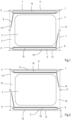
- Figure 1 shows a frame (1) provided with an aluminium sheet (2) as an insert moulded work product.
- the design of the frame shows an inlet (3) for a first gas flow and an outlet (4) for the first gas flow.
- the frame (1) is further provided with four openings (5,6,7,8) which will form the longitudinal conduit when the frames are stacked.
- the frame is further provided with a system (9) of gutters as formed by ridges (10) which extend upwards for the viewer of this figure from the plane of sheet (2). For a frame having a height and width of 35x38 cm the ridges (10) may extend 3 mm.
- the opposite side of the frame which is not visible in Figure 1 is flat.
- the gutters form the branched conduits.
- the dimensions of these gutters may have a cross-sectional area of between 5 and 20 mm 2 .
- a fluid connection is present as shown. This results in that when a stack is formed the longitudinal conduits are fluidly connected to the branched conduits.
- the stack is suitably used in a horizontal position.
- the sides of the stack and the sides of the frames (1,1a) are therefore referred to as the upper side (11), lower side (12) and sides (13,14).
- Figures 1 and 2 also shows an opening (18) which will not be filled with the melt of plastic material.
- a space for water will then be present which runs along upper side (11).
- an inlet (not shown) to this space for water and by providing openings (not shown) to certain spaces between frames (1) and (1a) an evaporating plate heat exchanger may be obtained.
- the water from this space is fed to these spaces where it may evaporate.
- an opening (19) may be present which is also not filled with the melt of plastic material.
- This space may be used to collect any not evaporated water from the above spaces. Openings (not shown) will then be present to allow water to enter these lower space running along lower side (12).
- a discharge for collected water (not shown) is present to discharge this water.
- Figure 2 shows a frame (1a).
- This frame is as frame (1) except that the shows an inlet (15) for a second gas flow and an outlet (16) for the second gas flow.
- frames (1) and frames (1a) are stacked in an alternating order a row of inlets (3) will be present at one side in the lower half and a row of outlets (15) will be present at the same side (13) in the upper half of this side (13).
- This allows one to attach a header for supplying the first gas to the lower side of the stack and attach a header for collecting the second gas flow at the upper side of the stack making use of ridges (17).
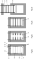
- Figures 3a-3d illustrate the process according to this invention.
- Figure 3a shows a mould (20) and a cover (21) enclosing the mould (20) as the container in a closed position.
- a stack (22) of eight frames (1,1a) are placed in the mould (20) .
- the inner shape of mould (20) just allows positioning stack (22) in the mould.
- the thickness of the frames is not to scale. For clarity reasons a thicker frame is drawn such that the invention can be better illustrated.
- the stack (22) comprises four longitudinal conduits (23) of which two are shown. These conduits are formed by openings (5,6,7,8) in the frames (1,1a).
- the cover (21) is provided with four inlets (25) for the pressurised melt of a plastic. These inlets (25) are fluidly connected to the longitudinal conduits (23) as shown.
- the longitudinal conduits (23) are connected to the branched conduits (24) as schematically shown.
- a melt of a plastic is supplied via the inlets (25) to the longitudinal conduits (23) of the stack (22) of Figure 3a .
- the melt flows from the individual longitudinal conduits (23) via the branched conduits (24) as illustrated by the smaller arrows (26).
- the supply of the melt of the plastic stops when all of the branched conduits are filled with the melt (27) as shown in Figure 3c .
- the connected stack (22) is removed from the mould (20) by lifting the cover (21).
- the connected stack (22) is connected to the cover (21) by means of the solidified plastic in the inlets (25) forming one mass with the solidified plastic in the longitudinal conduits (23).
Landscapes
- Engineering & Computer Science (AREA)
- Mechanical Engineering (AREA)
- Manufacturing & Machinery (AREA)
- Physics & Mathematics (AREA)
- Thermal Sciences (AREA)
- General Engineering & Computer Science (AREA)
- Stackable Containers (AREA)
- Laminated Bodies (AREA)
- Moulds For Moulding Plastics Or The Like (AREA)
- Injection Moulding Of Plastics Or The Like (AREA)
- Buffer Packaging (AREA)
- Heat-Exchange Devices With Radiators And Conduit Assemblies (AREA)
Claims (18)
- Verfahren, um einen untereinander verbundenen Stapel aus thermoplastischen Rahmen (1) herzustellen, aufweisend zwei Seiten, durchStapeln der thermoplastischen Rahmen (1,1a), um einen Stapel (22) aus Rahmen (1) zu erhalten, sodass die einander zugewandten Seiten von zwei benachbarten Rahmen (1,1a) an einer Kontaktfläche miteinander in Kontakt stehen,wobei aufgrund des Stapelns der Rahmen (1,1a) und aufgrund dessen, dass mindestens eine Öffnung (5,6,7,8) in dem Rahmen (1,1a) vorhanden ist, mindestens eine Längsleitung (23) ausgebildet wird, die entlang der Länge des Stapels (22) verläuft,wobei aufgrund des Stapelns der Rahmen (1,1a) und aufgrund einer an oder in mindestens einer Seite des Rahmens an der Kontaktfläche vorhandenen länglichen Rinne, eine verzweigte Leitung (24) an der Kontaktfläche ausgebildet wird, wobei die verzweigte Leitung (24) mit der Längsleitung (23) fluidisch verbunden ist und wobei eine unter Druck stehende Schmelze eines Kunststoffmaterials der länglichen Leitung (23) und den verzweigten Leitungen (24) zugeführt wird, während der Stapel (22) durch ein externes Mittel (20) zusammengehalten wird, um den untereinander verbundenen Stapel (22) aus thermoplastischen Rahmen zu erhalten.
- Verfahren nach Anspruch 1, wobei die Schmelze eines Kunststoffmaterials eine Schmelze eines thermoplastischen Elastomers ist.
- Verfahren nach einem der Ansprüche 1 bis 2, wobei die thermoplastischen Rahmen (1,1a) Polypropylenrahmen, Polyethylenrahmen oder Polyamidrahmen sind.
- Verfahren nach einem der Ansprüche 1 bis 3, wobei die Rahmen (1,1a) durch Spritzgießen erhalten werden.
- Verfahren nach Anspruch 4, wobei die Rahmen (1,1a) einsatzgegossene Arbeitsprodukte sind, umfassend einen Einsatz, bestehend aus einem Wärmeübertragungsblech.
- Verfahren nach Anspruch 5, wobei die Rahmen (1,1a) Polypropylenrahmen sind und der Einsatz ein Aluminiumblech ist und wobei die unter Druck stehende Schmelze eines Kunststoffs eine unter Druck stehende Schmelze eines Styrol-Ethylen-Butylen-Styrol-Blockcopolymers ist.
- Verfahren nach einem der Ansprüche 1 bis 6, wobei mindestens zwei Längsleitungen (23) aufgrund des Stapelns der Rahmen ausgebildet werden und wobei die mindestens zwei Längsleitungen (23) nicht fluidisch miteinander verbunden sind und wobei die zwei länglichen Leitungen (23) jeweils mit separaten verzweigten Leitungen (24) fluidisch verbunden sind.
- Verfahren nach einem der Ansprüche 1 bis 7, wobei das externe Mittel ein Behälter (20) ist, aufweisend eine offene und eine geschlossen Position, der eine Innengestalt aufweist, die das Formnegativ des untereinander verbundenen Stapels (22) ist, wenn er sich in der geschlossenen Position befindet, und wobei der Behälter ein Positionieren des Stapels (22) aus thermoplastischen Rahmen und ein Entfernen des untereinander verbundenen Stapels (22) aus thermoplastischen Rahmen ermöglicht, wenn er sich in der offenen Position befindet, und wobei der Behälter (20) mit mindestens einem Einlass (25) für die unter Druck stehende Schmelze eines Kunststoffs versehen ist und wobei mindestens ein Einlass (25) mit der mindestens einen Längsleitung (23) fluidisch verbunden ist, wenn sich der Behälter in einer geschlossenen Position befindet.
- Verfahren nach Anspruch 8, wobei dem Stapel (22) eine zusätzliche Kammer hinzugefügt wird, um einen Stapel (22) mit der zusätzlichen Kammer zu erhalten, und wobei der Behälter eine Innengestalt aufweist, die das Formnegativ des untereinander verbundenen Stapels mit der zusätzlichen Kammer ist, und wobei das zusätzliche Teil durch die Schmelze eines dem Behälter zugeführten Kunststoffmaterials mit dem Stapel verbunden wird.
- Untereinander verbundener Stapel nach einem der Ansprüche 1 bis 9, wobei der Stapel aus untereinander verbundenen Rahmen (22) geeignet ist, um ein Teil eines Plattenwärmetauschers zu sein.
- Untereinander verbundener Stapel (22) aus thermoplastischen Rahmen (1,1a), aufweisend zwei Seiten, wobei die einander zugewandten Seiten von zwei benachbarten Rahmen durch Fusionsbonden an einer Kontaktfläche verbunden und durch das Verfahren nach einem der vorstehenden Ansprüche erhalten werden.
- Untereinander verbundener Stapel aus thermoplastischen Rahmen nach Anspruch 11, wobei das thermoplastische Elastomer ein Styrol-Ethylen-Butylen-Styrol-Blockcopolymer ist.
- Untereinander verbundener Stapel nach einem der Ansprüche 11 bis 12, wobei die thermoplastischen Rahmen (1,1a) Polypropylenrahmen, Polyethylenrahmen oder Polyamidrahmen sind.
- Untereinander verbundener Stapel nach einem der Ansprüche 11 bis 13, wobei das Wärmeaustauschblech ein Metallblech ist.
- Untereinander verbundener Stapel nach Anspruch 14, wobei die thermoplastischen Rahmen (1,1a) Polypropylenrahmen sind und das Wärmeaustauschblech ein Aluminiumblech ist.
- Untereinander verbundener Stapel nach einem der Ansprüche 11 bis 15, wobei eine zusätzliche Kammer mit einer Seite des Stapels verbunden ist.
- Untereinander verbundener Stapel nach Anspruch 16, wobei die zusätzliche Kammer ein spritzgegossenes Teil ist, das aus dem gleichen thermoplastischen Material wie die Rahmen hergestellt und durch Fusionsbonden mit der Seite des Stapels verbunden ist.
- Untereinander verbundener Stapel nach einem der Ansprüche 14 bis 17 als Teil eines Plattenwärmetauschers.
Applications Claiming Priority (2)
| Application Number | Priority Date | Filing Date | Title |
|---|---|---|---|
| NL2027649A NL2027649B1 (en) | 2021-02-25 | 2021-02-25 | Process to manufacture an interconnected stack of thermoplastic frames |
| PCT/EP2022/054627 WO2022180151A1 (en) | 2021-02-25 | 2022-02-24 | Process to manufacture an interconnected stack of thermoplastic frames |
Publications (3)
| Publication Number | Publication Date |
|---|---|
| EP4297948A1 EP4297948A1 (de) | 2024-01-03 |
| EP4297948C0 EP4297948C0 (de) | 2025-04-16 |
| EP4297948B1 true EP4297948B1 (de) | 2025-04-16 |
Family
ID=75108749
Family Applications (1)
| Application Number | Title | Priority Date | Filing Date |
|---|---|---|---|
| EP22708537.0A Active EP4297948B1 (de) | 2021-02-25 | 2022-02-24 | Verfahren zur herstellung eines stapels untereinander verbundener rahmen |
Country Status (14)
| Country | Link |
|---|---|
| US (1) | US20240227265A9 (de) |
| EP (1) | EP4297948B1 (de) |
| JP (1) | JP2024509102A (de) |
| KR (1) | KR20230151514A (de) |
| CN (1) | CN116887966A (de) |
| AU (1) | AU2022227186A1 (de) |
| CA (1) | CA3209107A1 (de) |
| ES (1) | ES3025196T3 (de) |
| IL (1) | IL305097A (de) |
| MX (1) | MX2023009179A (de) |
| NL (1) | NL2027649B1 (de) |
| PL (1) | PL4297948T3 (de) |
| WO (1) | WO2022180151A1 (de) |
| ZA (1) | ZA202307312B (de) |
Family Cites Families (12)
| Publication number | Priority date | Publication date | Assignee | Title |
|---|---|---|---|---|
| DE2555079C3 (de) * | 1975-12-06 | 1979-06-07 | Basf Ag, 6700 Ludwigshafen | Vorrichtung zum Temperieren von hochviskosen Lösungen oder Schmelzen thermoplastischer Kunststoffe |
| JP2002372393A (ja) * | 2001-06-19 | 2002-12-26 | Matsushita Seiko Co Ltd | 熱交換素子とその製造方法 |
| CN2762044Y (zh) * | 2003-11-14 | 2006-03-01 | 张洪 | 注塑装配成型的逆流或交叉流平板式空气热量交换器 |
| JP4816517B2 (ja) | 2006-09-28 | 2011-11-16 | パナソニック株式会社 | 熱交換素子 |
| EP2614764A3 (de) * | 2012-01-12 | 2017-03-29 | Winterhalter Gastronom Gmbh | Abwasserwärmetauscher für Geschirrspülmaschinen sowie Geschirrspülmaschine |
| CA2879447C (en) * | 2012-07-19 | 2018-02-06 | Asahi Kasei Fibers Corporation | Multilayered structure comprising fine fiber cellulose layer |
| RU2694379C1 (ru) | 2015-06-22 | 2019-07-12 | Дач Инновейшн Ин Эр Тритмент Бв | Здание, снабженное системой обработки воздуха |
| CN105241296B (zh) | 2015-09-25 | 2018-09-14 | 森德(中国)暖通设备有限公司 | 热交换器 |
| NL2018175B1 (nl) * | 2017-01-16 | 2018-07-26 | Recair Holding B V | Recuperator |
| US10113767B1 (en) * | 2018-02-01 | 2018-10-30 | Berg Companies, Inc. | Air handling unit |
| WO2020045003A1 (ja) * | 2018-08-31 | 2020-03-05 | パナソニックIpマネジメント株式会社 | 熱交換素子及びそれを用いた熱交換形換気装置 |
| US11584049B2 (en) * | 2019-08-02 | 2023-02-21 | Arris Composites Inc. | Structural foam molding method using continuous fiber composites, and parts formed therefrom |
-
2021
- 2021-02-25 NL NL2027649A patent/NL2027649B1/en active
-
2022
- 2022-02-24 KR KR1020237027453A patent/KR20230151514A/ko active Pending
- 2022-02-24 IL IL305097A patent/IL305097A/en unknown
- 2022-02-24 ES ES22708537T patent/ES3025196T3/es active Active
- 2022-02-24 PL PL22708537.0T patent/PL4297948T3/pl unknown
- 2022-02-24 CA CA3209107A patent/CA3209107A1/en active Pending
- 2022-02-24 JP JP2023551723A patent/JP2024509102A/ja active Pending
- 2022-02-24 CN CN202280016665.4A patent/CN116887966A/zh active Pending
- 2022-02-24 US US18/546,990 patent/US20240227265A9/en active Pending
- 2022-02-24 AU AU2022227186A patent/AU2022227186A1/en active Pending
- 2022-02-24 EP EP22708537.0A patent/EP4297948B1/de active Active
- 2022-02-24 MX MX2023009179A patent/MX2023009179A/es unknown
- 2022-02-24 WO PCT/EP2022/054627 patent/WO2022180151A1/en not_active Ceased
-
2023
- 2023-07-21 ZA ZA2023/07312A patent/ZA202307312B/en unknown
Also Published As
| Publication number | Publication date |
|---|---|
| US20240131763A1 (en) | 2024-04-25 |
| WO2022180151A1 (en) | 2022-09-01 |
| US20240227265A9 (en) | 2024-07-11 |
| CN116887966A (zh) | 2023-10-13 |
| EP4297948C0 (de) | 2025-04-16 |
| AU2022227186A1 (en) | 2023-08-10 |
| ZA202307312B (en) | 2024-11-27 |
| CA3209107A1 (en) | 2022-09-01 |
| IL305097A (en) | 2023-10-01 |
| ES3025196T3 (en) | 2025-06-06 |
| MX2023009179A (es) | 2023-10-23 |
| EP4297948A1 (de) | 2024-01-03 |
| KR20230151514A (ko) | 2023-11-01 |
| PL4297948T3 (pl) | 2025-08-11 |
| NL2027649B1 (en) | 2022-09-20 |
| NL2027649A (en) | 2022-09-20 |
| JP2024509102A (ja) | 2024-02-29 |
Similar Documents
| Publication | Publication Date | Title |
|---|---|---|
| EP0954362B1 (de) | Wärmeaustauscher | |
| US20170317394A1 (en) | Heat exchanger for a battery | |
| NL2018175B1 (nl) | Recuperator | |
| WO2011088997A1 (de) | Temperierbare batteriezellenanordnung | |
| CN103872405A (zh) | 热交换器安排 | |
| EP3745076A1 (de) | Rohrsammelkasten und wärmetauscher | |
| SK280079B6 (sk) | Puzdro akumulátora | |
| EP4297948B1 (de) | Verfahren zur herstellung eines stapels untereinander verbundener rahmen | |
| US20200153065A1 (en) | Accumulator arrangement | |
| AU2019410407B2 (en) | Mould configuration | |
| WO2019081769A1 (en) | UNIT AND HEAT EXCHANGE ASSEMBLY | |
| EP4298393B1 (de) | Verdampferplattenwärmetauscher | |
| US7261285B2 (en) | Internal inserts in cooling towers | |
| JP2024509102A5 (de) | ||
| NL2034333B1 (en) | Process for manufacture of heat exchanger | |
| CN222688509U (zh) | 制冰隔板及蒸发器 | |
| EP4529977A1 (de) | Destillationssystem | |
| BR112023015920B1 (pt) | Trocador de calor a placas evaporativas | |
| RU2197692C2 (ru) | Теплообменник |
Legal Events
| Date | Code | Title | Description |
|---|---|---|---|
| STAA | Information on the status of an ep patent application or granted ep patent |
Free format text: STATUS: UNKNOWN |
|
| STAA | Information on the status of an ep patent application or granted ep patent |
Free format text: STATUS: THE INTERNATIONAL PUBLICATION HAS BEEN MADE |
|
| PUAI | Public reference made under article 153(3) epc to a published international application that has entered the european phase |
Free format text: ORIGINAL CODE: 0009012 |
|
| STAA | Information on the status of an ep patent application or granted ep patent |
Free format text: STATUS: REQUEST FOR EXAMINATION WAS MADE |
|
| 17P | Request for examination filed |
Effective date: 20230825 |
|
| AK | Designated contracting states |
Kind code of ref document: A1 Designated state(s): AL AT BE BG CH CY CZ DE DK EE ES FI FR GB GR HR HU IE IS IT LI LT LU LV MC MK MT NL NO PL PT RO RS SE SI SK SM TR |
|
| DAV | Request for validation of the european patent (deleted) | ||
| DAX | Request for extension of the european patent (deleted) | ||
| STAA | Information on the status of an ep patent application or granted ep patent |
Free format text: STATUS: EXAMINATION IS IN PROGRESS |
|
| 17Q | First examination report despatched |
Effective date: 20241002 |
|
| GRAP | Despatch of communication of intention to grant a patent |
Free format text: ORIGINAL CODE: EPIDOSNIGR1 |
|
| STAA | Information on the status of an ep patent application or granted ep patent |
Free format text: STATUS: GRANT OF PATENT IS INTENDED |
|
| GRAS | Grant fee paid |
Free format text: ORIGINAL CODE: EPIDOSNIGR3 |
|
| GRAA | (expected) grant |
Free format text: ORIGINAL CODE: 0009210 |
|
| STAA | Information on the status of an ep patent application or granted ep patent |
Free format text: STATUS: THE PATENT HAS BEEN GRANTED |
|
| INTG | Intention to grant announced |
Effective date: 20250217 |
|
| AK | Designated contracting states |
Kind code of ref document: B1 Designated state(s): AL AT BE BG CH CY CZ DE DK EE ES FI FR GB GR HR HU IE IS IT LI LT LU LV MC MK MT NL NO PL PT RO RS SE SI SK SM TR |
|
| REG | Reference to a national code |
Ref country code: GB Ref legal event code: FG4D |
|
| REG | Reference to a national code |
Ref country code: CH Ref legal event code: EP |
|
| REG | Reference to a national code |
Ref country code: IE Ref legal event code: FG4D |
|
| REG | Reference to a national code |
Ref country code: DE Ref legal event code: R096 Ref document number: 602022013232 Country of ref document: DE |
|
| REG | Reference to a national code |
Ref country code: ES Ref legal event code: FG2A Ref document number: 3025196 Country of ref document: ES Kind code of ref document: T3 Effective date: 20250606 |
|
| U01 | Request for unitary effect filed |
Effective date: 20250508 |
|
| U07 | Unitary effect registered |
Designated state(s): AT BE BG DE DK EE FI FR IT LT LU LV MT NL PT RO SE SI Effective date: 20250515 |
|
| REG | Reference to a national code |
Ref country code: GR Ref legal event code: EP Ref document number: 20250401082 Country of ref document: GR Effective date: 20250707 |
|
| PG25 | Lapsed in a contracting state [announced via postgrant information from national office to epo] |
Ref country code: NO Free format text: LAPSE BECAUSE OF FAILURE TO SUBMIT A TRANSLATION OF THE DESCRIPTION OR TO PAY THE FEE WITHIN THE PRESCRIBED TIME-LIMIT Effective date: 20250716 |
|
| PG25 | Lapsed in a contracting state [announced via postgrant information from national office to epo] |
Ref country code: HR Free format text: LAPSE BECAUSE OF FAILURE TO SUBMIT A TRANSLATION OF THE DESCRIPTION OR TO PAY THE FEE WITHIN THE PRESCRIBED TIME-LIMIT Effective date: 20250416 |
|
| PG25 | Lapsed in a contracting state [announced via postgrant information from national office to epo] |
Ref country code: RS Free format text: LAPSE BECAUSE OF FAILURE TO SUBMIT A TRANSLATION OF THE DESCRIPTION OR TO PAY THE FEE WITHIN THE PRESCRIBED TIME-LIMIT Effective date: 20250716 |
|
| PG25 | Lapsed in a contracting state [announced via postgrant information from national office to epo] |
Ref country code: IS Free format text: LAPSE BECAUSE OF FAILURE TO SUBMIT A TRANSLATION OF THE DESCRIPTION OR TO PAY THE FEE WITHIN THE PRESCRIBED TIME-LIMIT Effective date: 20250816 |
|
| PG25 | Lapsed in a contracting state [announced via postgrant information from national office to epo] |
Ref country code: SM Free format text: LAPSE BECAUSE OF FAILURE TO SUBMIT A TRANSLATION OF THE DESCRIPTION OR TO PAY THE FEE WITHIN THE PRESCRIBED TIME-LIMIT Effective date: 20250416 |
|
| PG25 | Lapsed in a contracting state [announced via postgrant information from national office to epo] |
Ref country code: CZ Free format text: LAPSE BECAUSE OF FAILURE TO SUBMIT A TRANSLATION OF THE DESCRIPTION OR TO PAY THE FEE WITHIN THE PRESCRIBED TIME-LIMIT Effective date: 20250416 |
|
| PG25 | Lapsed in a contracting state [announced via postgrant information from national office to epo] |
Ref country code: SK Free format text: LAPSE BECAUSE OF FAILURE TO SUBMIT A TRANSLATION OF THE DESCRIPTION OR TO PAY THE FEE WITHIN THE PRESCRIBED TIME-LIMIT Effective date: 20250416 |
|
| PLBE | No opposition filed within time limit |
Free format text: ORIGINAL CODE: 0009261 |
|
| STAA | Information on the status of an ep patent application or granted ep patent |
Free format text: STATUS: NO OPPOSITION FILED WITHIN TIME LIMIT |
|
| REG | Reference to a national code |
Ref country code: CH Ref legal event code: L10 Free format text: ST27 STATUS EVENT CODE: U-0-0-L10-L00 (AS PROVIDED BY THE NATIONAL OFFICE) Effective date: 20260225 |
|
| 26N | No opposition filed |
Effective date: 20260119 |
|
| U20 | Renewal fee for the european patent with unitary effect paid |
Year of fee payment: 5 Effective date: 20260227 |
|
| PGFP | Annual fee paid to national office [announced via postgrant information from national office to epo] |
Ref country code: GB Payment date: 20260227 Year of fee payment: 5 |
|
| PGFP | Annual fee paid to national office [announced via postgrant information from national office to epo] |
Ref country code: ES Payment date: 20260302 Year of fee payment: 5 |
|
| PGFP | Annual fee paid to national office [announced via postgrant information from national office to epo] |
Ref country code: TR Payment date: 20260206 Year of fee payment: 5 |
|
| PGFP | Annual fee paid to national office [announced via postgrant information from national office to epo] |
Ref country code: PL Payment date: 20260203 Year of fee payment: 5 Ref country code: GR Payment date: 20260226 Year of fee payment: 5 |