EP4529977A1 - Destillationssystem - Google Patents
Destillationssystem Download PDFInfo
- Publication number
- EP4529977A1 EP4529977A1 EP23200404.4A EP23200404A EP4529977A1 EP 4529977 A1 EP4529977 A1 EP 4529977A1 EP 23200404 A EP23200404 A EP 23200404A EP 4529977 A1 EP4529977 A1 EP 4529977A1
- Authority
- EP
- European Patent Office
- Prior art keywords
- steam
- frame
- sealing
- inner area
- feed
- Prior art date
- Legal status (The legal status is an assumption and is not a legal conclusion. Google has not performed a legal analysis and makes no representation as to the accuracy of the status listed.)
- Pending
Links
Images


Classifications
-
- B—PERFORMING OPERATIONS; TRANSPORTING
- B01—PHYSICAL OR CHEMICAL PROCESSES OR APPARATUS IN GENERAL
- B01D—SEPARATION
- B01D61/00—Processes of separation using semi-permeable membranes, e.g. dialysis, osmosis or ultrafiltration; Apparatus, accessories or auxiliary operations specially adapted therefor
- B01D61/36—Pervaporation; Membrane distillation; Liquid permeation
- B01D61/364—Membrane distillation
- B01D61/3641—Membrane distillation comprising multiple membrane distillation steps
-
- B—PERFORMING OPERATIONS; TRANSPORTING
- B01—PHYSICAL OR CHEMICAL PROCESSES OR APPARATUS IN GENERAL
- B01D—SEPARATION
- B01D5/00—Condensation of vapours; Recovering volatile solvents by condensation
- B01D5/0003—Condensation of vapours; Recovering volatile solvents by condensation by using heat-exchange surfaces for indirect contact between gases or vapours and the cooling medium
- B01D5/0015—Plates
-
- B—PERFORMING OPERATIONS; TRANSPORTING
- B01—PHYSICAL OR CHEMICAL PROCESSES OR APPARATUS IN GENERAL
- B01D—SEPARATION
- B01D1/00—Evaporating
- B01D1/22—Evaporating by bringing a thin layer of the liquid into contact with a heated surface
- B01D1/221—Composite plate evaporators
-
- B—PERFORMING OPERATIONS; TRANSPORTING
- B01—PHYSICAL OR CHEMICAL PROCESSES OR APPARATUS IN GENERAL
- B01D—SEPARATION
- B01D1/00—Evaporating
- B01D1/30—Accessories for evaporators ; Constructional details thereof
-
- B—PERFORMING OPERATIONS; TRANSPORTING
- B01—PHYSICAL OR CHEMICAL PROCESSES OR APPARATUS IN GENERAL
- B01D—SEPARATION
- B01D5/00—Condensation of vapours; Recovering volatile solvents by condensation
- B01D5/0057—Condensation of vapours; Recovering volatile solvents by condensation in combination with other processes
- B01D5/006—Condensation of vapours; Recovering volatile solvents by condensation in combination with other processes with evaporation or distillation
-
- B—PERFORMING OPERATIONS; TRANSPORTING
- B01—PHYSICAL OR CHEMICAL PROCESSES OR APPARATUS IN GENERAL
- B01D—SEPARATION
- B01D2311/00—Details relating to membrane separation process operations and control
- B01D2311/10—Temperature control
- B01D2311/106—Cooling
- B01D2311/1061—Cooling between serial separation steps
-
- B—PERFORMING OPERATIONS; TRANSPORTING
- B01—PHYSICAL OR CHEMICAL PROCESSES OR APPARATUS IN GENERAL
- B01D—SEPARATION
- B01D2313/00—Details relating to membrane modules or apparatus
- B01D2313/22—Cooling or heating elements
- B01D2313/221—Heat exchangers
-
- B—PERFORMING OPERATIONS; TRANSPORTING
- B01—PHYSICAL OR CHEMICAL PROCESSES OR APPARATUS IN GENERAL
- B01D—SEPARATION
- B01D2317/00—Membrane module arrangements within a plant or an apparatus
- B01D2317/04—Elements in parallel
Definitions
- the present disclosure is related to a distillation system, in particular for producing a distillate (e.g. sterile water).
- the distillation system may in particular comprise a modular flow system comprising a plurality of frame elements.
- Modular flow systems comprising a plurality of frame elements are known e.g. from EP2427263 (A1 ) (or US2012038069 (A1 ) of the same family).
- the plurality of frame elements can be combined by means of welded web structures to various stacks comprising in each case at least two, in particular at least ten frame elements, in order to form a membrane distillation stage.
- the frame elements comprise in each case an outer frame provided with passage openings and vapor and/or liquid channels as well as a central inner region surrounded by the outer frame.
- the vapor and/or liquid channels are arranged on the left and right sides of a respective frame element when combined together to form the modular flow system.
- a pervaporation membrane is used, for example, to overcome the azeotropic point in the separation of multi-substance mixtures, such as alcohol and water, which cannot be overcome by conventional distillation methods.
- EP 2 627 437 B1 describes a multistage membrane distillation device comprising a heating stage, preferably multiple condensing/evaporating stages, and a condensing stage through which a liquid to be concentrated is passed in succession.
- Each condensing/evaporating stage comprises at least one condensing unit and at least one evaporating unit.
- Each condensing unit comprises a first steam chamber that is delimited at least partly by a condensation wall, and each evaporating unit comprises a second steam chamber that is delimited at least partly by a steam-permeable liquid-tight membrane wall.
- a further device for distilling solutions using a membrane is known from WO 2005/089914 A1 .
- the apparatus comprises a plurality of multistage membrane distillation modules.
- the frame elements of the apparatus comprise channel openings in the form through holes inside an a frame wall of the inner frame. Said frame wall separates an inner region of a frame element from a vapor and/or liquid channels. Said through holes require a relatively complex manufacturing process (e.g. requiring the use of special injection mold tools in an injection molding process). Moreover, no non-destructive inspection of the inner region is possible.
- Modular, i.e. frame-based flow systems have shown to be useful in practice due to their high flexibility. However, they may imply disadvantages in terms of maintenance, as the inside of the welded stacks of frame-elements may not be accessible from outside, e.g. for cleaning. Therefore, e.g. salt crystals or other solids remaining on the surface of (porous) membranes may only hardly be removed. Such flow systems may thus be less suitable for specific functions, e.g. for a crystallization process. In a crystallization process, a feed liquid is concentrated until saturation, i.e. until crystals grow.
- the present disclosure relates to a distillation system for concentrating a feed liquid, comprising at least one condensation unit and at least one adjacent evaporation unit, each unit being provided by at least one frame element.
- the frame elements of the system are assembled together to form a stack of frame elements.
- Each frame element comprises:
- the first group comprises a feed connection notch connecting a feed channel with the inner area.
- Each frame element further comprises:
- each condensation unit may be equipped with a liquid-tight condensing surface, which covers the open inner area and tightly separates the feed and steam sides.
- the distillation system By providing such a system, it becomes possible to open the distillation system in a non-destructive manner, i.e. to demount or de-assemble the assembled frame elements. Therefore, it becomes possible to clean the inner regions of a used system and e.g. remove salt or other particles or elements, e.g. in case of scaling, fouling or clogging. Furthermore, in case of a production defect or damage of a single frame element, the defective single part can be exchanged. The system can be re-assembled afterwards.
- the sealing elements may be removeable and may replace a welding, i.e. the frame elements do not need to be welded to each other.
- the production can be further simplified, since only one frame type may be sufficient what is especially beneficial in injection molding process. Moreover, the sealing may take place on one side only.
- the specific function of the (basically standardized) frame element may be defined by the specific sealing element. Since such a specific sealing element is arranged between two adjacent frame elements (and thus giving the function to this couple and/or to the space between the couple of frame elements), the frame elements may also be referred to as "half frames".
- the manufacturing process is less complex, because the frame elements do not require through holes inside a frame wall of the frame element. Said frame wall may separate an inner area of a frame element from a channel. Hence, an injection molding process for manufacturing the frame elements is less complex, as no specific shifter tools are required.
- the system of the present disclosure also provides several advantages compared to a conventional plate distillation apparatus (e.g. comparable to a conventional heat exchanger):
- liquid tight wall e.g. a foil
- membrane e.g. a membrane
- the condensing and evaporating surfaces of the system may be (at least slightly) flexible or moveable. As a result, adhesions can be loosened more easily.
- system of the present disclosure can be relatively inexpensive, since rather inexpensive materials are required for manufacturing the system.
- each frame element may further comprise a sealing area surrounding the inner area and arranged on the feed side.
- Each frame element may further comprise a sealing groove arranged on both the feed side and the steam side and configured to receive a sealing element which connects adjacent frame elements.
- Each frame element may be axis symmetrical with the axis of symmetry vertical when the frame elements are stacked together in the system.
- at least one of the following elements of the system may be desirably symmetrical: the sealing groove, the channels 8and optionally the connection notches), and the inner area.
- a symmetry of the outer shape of the frame elements is possible but not necessary.
- the inner region may provide an open 3D (three-dimensional) space surrounded by the frame element.
- a grid element may be arranged in the open space of the inner area.
- the different sealing types may be configured to leave different connection notches unblocked.
- the different sealing types may be made of the same base type, wherein different sections may be cut off.
- the system may be configured such that at least one sealing element may be removeable from the frame elements. This may facilitate maintenance or cleaning of the system, as well as replacing single elements, e.g. a single sealing element or a single frame element.
- the sealing types may comprise at least a first type being a condensation sealing, a second type being a feeding sealing and a third type being an evaporation sealing.
- the condensation sealing may be configured to block all connection notches except:
- the feeding sealing may be configured to block all connection notches except:
- the evaporation sealing may be configured to block all connection notches except:
- the first group may further comprise a concentrate connection notch connecting a concentrate channel with the inner area.
- this concentrate connection notch may also be part of the second group, i.e. be arranged on the steam side, e.g. in case the evaporation unit does not comprise a membrane element.
- a feed liquid passing the inner area may namely be evacuated by a concentrate connection notch arranged on the steam side of an adjacent frame element
- the frame elements of the system may basically be made of the same base type.
- a first frame type may be a condensation frame comprising a liquid tight wall in the form of a foil attached to the sealing area to cover the inner area and/or the space of the inner area on the feed side.
- a second frame type may be an evaporation frame which may comprise a membrane attached to the sealing area to cover the inner area and/or the space of the inner area on the feed side.
- the second frame type may be an evaporation frame, wherein the inner area and/or the space of the inner area may be open on the feed side, i.e. open towards an adjacent frame element or in other words, without being covered by a membrane or a foil.
- the evaporation frame may be equipped with or without a membrane.
- the condensation unit may comprise two stacked condensation frames arranged such that their steam sides face each other.
- the evaporation unit may comprise two stacked evaporation frames arranged such that their steam sides face each other.
- the system may comprise a plurality of stacked condensation-evaporation sets.
- Each set may comprise a condensation unit and an evaporation unit, wherein the sets may be alternately connected via the steam sides so that the same unit types may be (always) adjacent to each other.
- the sets may be arranged such that the steam sides of the condensation units of two adjacent sets face each other, and the steam sides of the evaporation units of two adjacent sets face each other.
- the condensation frames of the condensation unit may be connected by a condensation sealing.
- the evaporation frames of the evaporation unit may be connected by an evaporation sealing.
- the frames of the condensation unit and of the evaporation unit may be adjacent to each other and connected by a feeding sealing.
- the channels may be provided by openings in the frame element from the feed side to the opposite steam side.
- connection notches may be arranged on a surface of one of the feed side and the steam side.
- the two steam channels may be arranged above the inner region.
- the distillate channel and the optional leakage channel may be arranged below the inner region.
- the feed channel may also be arranged above the inner region or on a lateral side of the inner region.
- the concentrate channel may be arranged below the inner region or on a lateral side of the inner region.
- the feed channel is be arranged below the inner region of the inner region, and the concentrate channel is arranged above the inner region.
- the channels and the notches may be arranged between the outer frame and the inner frame.
- Each frame element may comprise a lowered area having a reduce thickness compared to the outer area and/or outer frame.
- the lowered area may include at least one of the inner area, the inner frame, and a section of the frame element where the sealing area may be arranged.
- the section of the frame element where the sealing area may be arranged may be the inner frame.
- Each frame element may comprise a distribution notch on the feed side connected to the feed connection notch and configured to distribute a feed liquid across the inner area.
- the thickness of at least one of the inner frame, a section of the frame element where the sealing area may be arranged, and the grid element may be thinner than the outer frame.
- the feed spacer may be arranged in a feed space, which may be arranged between the condensation wall and a membrane.
- the feed spacer may be used to keep the feed space between the condensation wall and the adjacent membrane open, in order to allow a feed liquid to pass the feed space. In case a membrane is not used, the feed spacer is not required.
- Each membrane frame or at least one membrane frame may have a plane surface on the steam side, i.e. no lowered area.
- the present disclosure may further relate to a multistage distillation system, comprising a plurality of multistage distillation modules, the modules being configured to be flowed through in parallel by a liquid to be concentrated.
- Each module may comprise a plurality of serial condensation/evaporation stages configured to be flowed through in series or in parallel by the liquid to be concentrated.
- Each condensation/evaporation stage may comprise a plurality of parallel condensation/evaporation elements configured to be flowed through in parallel by the liquid to be concentrated.
- Each condensation/ evaporation element comprises at least one condensation unit and at least one evaporation unit.
- the system further desirably comprises at least one of: a centralized heating stage configured to generate steam and to provide the steam to each of the modules in parallel, and a centralized condensation stage configured to receive steam from each of the modules in parallel and to condensate the steam.
- the system may comprise up to several thousand condensation/evaporation elements, e.g. by simply combining several thousand first and a second frame elements, respectively.
- the energy consumption of the centralized (or single) heating stage and/or a centralized (or single) condensation stage may be shared by a plurality of parallel modules what leads to an optimized efficiency of the system and at the same time (due to the use of more than one module) to a higher total output of the system.
- the centralized heating and condensation stages can lead to a simplified design of the system, because several modules may be operated in parallel and each module does not require its own heating system.
- An increase in efficiency of the system may thus also be obtained and depends e.g. on the number of stages connected in series.
- the heat flow supplied at the front (i.e. at a first stage) and dissipated on the cold side (i.e. from the last stage toward the centralized condensation stage) may be used several times (i.e. at each stage from the first to the last stage) for condensation and evaporation due to the serial connection of the stages. If modules are connected in parallel, more heating heat may be required per additional module.
- the centralized heating stage generates steam (i.e. a vapor; the terms may be used interchangeably) and provides the steam to each of the modules in parallel. Accordingly the modules (i.e. desirably the respective first stages) are heated with the supplied steam.
- the present disclosure has the advantage that due to thermodynamics steam will automatically be attracted most by the coldest surface. Hence, a module which is colder than the others will automatically be heated more. As a consequence, the temperature of the modules (i.e. in particular of their respective first stages) is automatically balanced.
- the centralized heating stage may be configured to provide the steam in each module to a first stage of the serial condensation/evaporation stages.
- the first stage of each module may be heated by the centralized heating stage.
- the centralized heating stage may be configured to provide the steam in each module to the condensation units of the first stage in parallel, in particular for heating said condensation units to a first predetermined temperature.
- the centralized heating stage and/or the centralized condensation stage may be external to the modules, e.g. to the single stacks of frame elements forming the modules.
- the centralized heating stage and/or the centralized condensation stage may be connected to the modules by e.g. pipes, tubes and/or hoses.
- Each condensation/evaporation stage may be formed by a single stack of frame elements providing the parallel condensation/ evaporation elements.
- Each module may be formed by a single stack of frame elements providing the serial condensation/evaporation stages.
- Fig. 1a shows the schematic distillation process of fig. 1b , wherein the system does not have a membrane.
- Fig. 1b shows a schematic representation of a distillation process in a system having a membrane according to embodiments of the present disclosure.
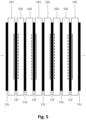
- the distillation process may be performed by a distillation system, as schematically shown in fig. 1a , and shown in the examples of fig. 3 and fig. 5 .
- the distillation system may be configured for concentrating a feed liquid F, e.g. dirt water or any solvent containing a salt.
- the system comprises at least one condensation unit and at least one adjacent evaporation unit.
- Each unit is provided by respective frame element 101, 102 assembled together to form a stack of frame elements (cf. e.g. fig. 3 and 5 ).
- the condensation unit may comprise a first steam space 40a and a condensation wall W at least partly bordering the first steam space 40a.
- the evaporation unit 102 may comprise a second steam space 40b.
- a feeding area 40' may be provided substantially between the condensation unit and the evaporation unit (and by a feeding sealing, as described in the context of fig. 3 and fig. 4b ). The feeding area 40' is bordered by the condensation wall.
- the system is configured such that the condensation wall can be heated by a first steam V1 in the first steam space 40a.
- the system is further configured such that feed liquid F flows on the condensation wall W in the feeding area, such that a second steam V2 arising from the feed liquid F moves into the second steam space 40b.
- the feeding area 40' may be open towards the second steam space 40b in the sense that there is desirably no membrane between the feeding area 40' and the second steam space 40b. However, there may be arranged a membrane M, as shown in fig. 1b .
- the condensation wall W may be flexible, wherein the condensation wall W optionally may comprise or may be a foil.
- the first steam space 40a may be connected to at least one vapor channel 17 by at least one first steam connection notch (as described in more detail in context of the subsequent figures) such that the first steam V1 can enter the first steam space.
- the first steam space 40a may be further connected a condensate collection passage 19a, 19b arranged below the first steam space 40a, e.g. by at least one distillate connection notch (as described in more detail in context of the subsequent figures).
- a condensate D resulting from the condensed first steam V1 may thus leave the first steam space 40a via said collection passage 19a, 19b (also cf. fig.2b ).
- the frame elements 101, 102 are configured (e.g. by a sealing element arranged between them, as explained in the context of fig. 3 and 4b ) such that a gap remains between the frame elements when they are stacked in the modular flow system.
- This gap in particular forms a feeding area 40' being aligned with the inner regions of the stacked frame elements and being in front of the first and second steam spaces 40a, 40b of the adjacent frame elements.
- the feeding area 40' is bordered on a first side by the condensation wall W (i.e. a liquid tight wall) toward the first steam space 40a.
- the condensation wall W i.e. a liquid tight wall
- the feeding area 40' may be open towards the second steam space 40b (cf. fig. 1a ) or may be bordered by a membrane M (cf. fig, 1b ).
- a feed (or feed liquid) F is supplied via the first passage opening 13 to the feeding area 40'.
- Said feed may be a liquid, e.g. salt water or dirt water which is distilled and/or cleaned by the modular flow system.
- the feed may have a temperature slightly lower than the vapor V1, e.g. a difference of 4 to 6°C.
- the feed F Due to the heat transferred from the condensing vapor V1, the feed F is heated and evaporates, such that the second steam V2 is generated. In this regard it is possible that the pressure within the feeding area or in parts of the modular flow system is reduced such that the feed boils when heated.
- the second steam V2 enters from the feeding area 40' the second steam space 40b of the frame element 102.
- Said steam V2 may have an equal or only a slightly lower temperature than the (boiling) feed F.
- the arrangement shown in Fig. 1a , 1b or 3 may be a first stage of a modular flow system (not shown).
- the vapor V2 leaving the second frame element 102 may be transmitted to a second stage of the modular flow system where it may be used as (heating) vapor in a first frame element 101 again.
- the modular flow system may have several stages (e.g. 10 or more) wherein in each subsequent stage the temperatures of the supplied vapor and feed are slightly decreased with regard to the preceding stage.
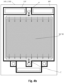
- the second steam space 40b may be connected to a vapor channel 18 by at least one a second steam connection notch (as described in more detail in context of the subsequent figures 2a to 4c ).
- the second steam space 40b may further be connected to the drain passage 20 by at least one drain or leakage connection notch 47f (as described in more detail in context of the subsequent figures 2a to 4c ).
- the second steam V2 may thus leave the second steam space 40b via the vapor channel 18 and/or the drain passage 20.
- the whole inner region 40 may serve as a barrier for droplets being carried with the flow of the created vapor V2.
- the feed would need to fill the complete inner region, in order to pass the barrier given by the configuration of the frame element, i.e. to flow into the vapor channel 18. Accordingly, there must be a proper separation of the steam V2 from feed.
- the vapor channels arranged in an upper area of the frame element are advantageous because of the gravity separation. Hence, any contamination of the final product (i.e. the distillate) can be effectively prevented.
- the condensation wall W may be moveable within the feeding area.
- the system may be configured such that the condensation wall may be deformed by the first steam into or towards the second steam space 40b.
- the system may be configured such that the condensation wall moves back to its initial position when the first steam may be stopped to enter the first steam space or in case of a pressure balance between the first and the second steam space.
- a feed spacer (not shown in fig. 1a or 1b ) may be arranged within the feeding area 40', as explained in more detail below.
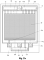
- Fig. 2a shows a schematic representation of the basic design of a feed side of a frame element 100 according to embodiments of the present disclosure
- Fig. 2b shows a schematic representation of the basic design of a steam side of a frame element 100 according to embodiments of the present disclosure.
- each frame element 100 of the system comprises a feed side 10f (cf. fig. 2a ) and an opposite steam side 10v (cf. fig. 2b ).
- An outer area of the frame element comprises a plurality of channels and an inner area 40.
- each frame element may comprise an outer frame and an inner frame, the inner frame encasing the inner region 40 and being surrounded by the outer frame.
- the channels and connection notches may be arranged between the outer frame and the inner frame.
- the plurality of channels may include at least one of a feed channel 13 above an inner area 40, a concentrate channel 16 below the inner area 40, two steam channels 17, 18 above an inner area 40, one or several distillate channel 19a, 19b below an inner area 40, and optionally a drain passage 20 below an inner area 40.
- a concentrate channel 16 and in addition a drain passage 20 may be in particular useful, in case the system comprises membranes, as it will be also explained in context of fig. 3 .
- the channels may be openings from the feed side to the steam side of the frame element.
- each frame element may be axis symmetrical with the axis of symmetry vertical when the frame elements are stacked together in the system.
- An inner area of the frame element 100 is basically open, encased by the outer area and limited by the feed side and the opposite steam side.
- the inner area may comprise a grid element. Depending on the function of the inner area it can be bordered (or limited) with a liquid tight wall on the feed side and optionally with a membrane on the steam side.
- Each frame element may further comprise a sealing area 12 surrounding the inner area and arranged on the feed side.
- the sealing area and the comprised inner area may be slightly thinner (in a side view like in fig. 5 ) than the outer area of the frame element. In this way, there is some remaining space between two adjacent frame elements 101, 102 in this sealing area for a feed spacer, which may be placed in a feed area (also cf. the flow of feed F between frame elements 101 and 102 in fig. 3 ).
- the sealing area 12 may also be referred to as a lowered area 12.
- the lowered area 12 may in particular serve to accommodate the feed spacer (not shown) and optionally at least one of the membrane M and the condensation wall W (depending on the frame type and the use of a one of these elements).
- the feed spacer may have a mesh-like form and be relatively thin, e.g. me have a thickness of 0.5mm or less.
- the frame element comprises on the feed side a first group of connection notches connecting some of the channels with the inner area.
- the first group comprises a first feed connection notch 47a connecting the feed channel 13 with the inner area and optionally a concentrate connection notch 47b connection the inner area with the concentrate channel 16.
- the concentrate connection notch 47b and the concentrate channel 16 are only necessary, in case the steam side is bordered (limited or covered) by a membrane. If not, the concentrate C may also leave the inner area via a drain connection notch 27f (arranged on the steam side of an adjacent frame element) and the drain passage 20 together with a potential leakage L, as it will be understood from fig. 3 .
- the feed connection notch 47 may be connected to a feed distribution notch 45a, which may extend in a horizontal direction across the upper side of the inner area 40.
- the concentrate connection notch may be connected to a concentrate collection notch 45b, which may extend in a horizontal direction across the lower side of the inner area 40.
- Each frame element further comprises a second group of connection notches arranged on the steam side and connecting others of the channels with the inner area.
- the second group comprises a first steam connection notch (or a plurality of steam connection notches to increase the steam flow) 47c connecting a first steam channel 18 with the inner area, a second steam connection notch (or a plurality of steam connection notches to increase the steam flow) 47d connecting a second steam channel 17 with the inner area, and a distillate connection notch 47e connecting a distillate channel 19a, 19b with the inner area.
- connection notch may be a groove in the (material of the) frame element.
- Each frame element may further comprise a sealing groove 11 arranged on both the feed side and the steam side and configured to receive the sealing element which connects adjacent frame elements.
- the system further comprises sealing elements 11c, 11f, 11e (cf. fig. 4a to 4c ) configured to connect adjacent frame elements.
- the outer areas of adjacent frame elements of the system may be in contact to each other.
- the sealing elements comprise different sealing types, as shown in fig. 4a to 4c , which are formed such that they block different connection notches.
- the different sealing types may be configured to leave different connection notches unblocked.
- the different sealing types may be made of the same base type, wherein different sections may be cut off.
- the system may be configured such that at least one sealing element may be removeable from the frame elements. This may facilitate maintenance or cleaning of the system, as well as replacing single elements, e.g. a single sealing element or a single frame element.
- Fig. 3 shows a schematic representation of a system with a membrane and four frame elements according to embodiments of the present disclosure, wherein the distillation system is schematically shown.
- Fig. 4b shows a schematic representation of the feed side of a first frame type 101 with a condensation wall W or of a second frame type 102 with membrane wall M and a placed feeding sealing 11f according to embodiments of the present disclosure.
- Fig. 4c shows a schematic representation of the steam side of a second frame type 102 with a placed evaporation sealing 11e according to embodiments of the present disclosure.
- the distillation (i.e. condensation and evaporation) process performed by the system shown in the example of fig. 3 may principally correspond to that one in fig. 1a or 1b .
- the frame types 101 and 102 may basically correspond to the frame element shown in fig. 2a and 2b .
- the frame elements 101, 102 of the system may basically be made of the same base type shown in fig. 2a and 2b .
- the different frame types 101 and 102 may merely differ from the basic frame element of fig. 2a , 2b and from each other by comprising (or not comprising) a sealed liquid tight wall W and/or an optional membrane M, as described in the following.
- different sealing types 11c, 11f, 11e may be used to connect adjacent frame elements. The sealing element may be removeable from the frame elements.
- the different frame types 101, 102 and their respective sealing types 11c, 11f, 11e of fig. 4a to 4c are also shown in fig. 3 in the form of a stack.
- This stack may constitute a distillation system.
- a first frame type 101 may be a condensation frame comprising a liquid tight wall W in the form of a foil attached to the sealing area to cover the inner area and/or the space of the inner area on the feed side.
- a second frame type 102 may be an evaporation frame which may comprise a membrane M attached to the sealing area to cover the inner area and/or the space of the inner area on the feed side.
- the second frame type may be an evaporation frame, wherein the inner area and/or the space of the inner area may be open on the feed side, i.e. open towards an adjacent frame element or in other words, without being covered by a membrane or a foil.
- the evaporation frame element 102 may be equipped with or without a membrane.
- the sealing types may comprise at least a first type being a condensation sealing 11c, a second type being a feeding sealing 11f and a third type being an evaporation sealing 11e.
- the condensation sealing 11c may be arranged between two adjacent frame elements 101, which both face the condensation sealing 11c with their steam side 10v (also cf. fig. 4a ). These two frame elements 101 may together be referred to as a condensation unit of the system.
- the evaporation sealing 11e may be arranged between two adjacent frame elements 102, which both face the evaporation sealing 11e with their steam side 10v (also cf. fig. 4c ). These two frame elements 102 may together be referred to as an evaporation unit of the system.
- a condensation frame 101 may be adjacent to an evaporation unit 102 in the stack and may be connected by a feeding sealing 11f with their feed side 10f.
- the condensation sealing 11c may be configured to block all connection notches except the first steam connection notch(es) 47c connecting a first steam channel 18 with the inner area, and the distillate connection notch(es) 47g, 47e connecting one or several distillate channels 19a, 19b with the inner area 40 (also cf. fig. 2b ). Accordingly, the condensation sealing 11c allow a vapor V1 to enter the inner area and a distillate D to leave the inner area (also cf. fig. 3 ).
- the feeding sealing 11f may be configured to block all connection notches except a feed connection notch 47a connecting a feed channel 13 with the inner area 40, and optionally a concentrate connection notch 47b connecting a concentrate channel 16 with the inner area, e.g. in case the evaporation frame comprises a membrane arranged on the feed side, or in case the connection notch to the concentrate channel is arranged on the steam side of the frame. Accordingly, the feeding sealing 11f allows a feed liquid F to enter the inner area and a concentrate C to leave the inner area (also cf. fig. 3 ).
- the evaporation sealing 11e may be configured to block all connection notches except steam connection notch(es) 47d connecting a further steam channel 17 with the inner area 40, and optionally additional leakage connection notch(es) 47f connecting a leakage channel 20 with the inner area 40. Accordingly, the evaporation sealing 11e allows a vapor V2 to leave the inner area and a potential leakage L to leave the inner area (also cf. fig. 3 ).
- the leakage channel may be present, in case the evaporation unit comprises a membrane. Otherwise the leakage channel may be combined with (or represented by) the existing concentrate channel of an adjacent frame element.
- the first group of connection notches arranged on the feed side 10f may further comprise a concentrate connection notch connecting a concentrate channel with the inner area.
- this concentrate connection notch may also be part of the second group, i.e. be arranged on the steam side, e.g. in case the evaporation unit does not comprise a membrane element.
- a feed liquid passing the inner area may namely be evacuated by a concentrate connection notch arranged on the steam side of an adjacent frame element.
- a vapor (or steam) V1 may enter the inner area of the first frame element 101 via a first vapor channel and condensate at the liquid tight frame wall W.
- a feed liquid F entering a gap between the first and the second frame type 101, 102 may evaporate due to the heat transferred by the condensing vapor.
- the resulting evaporated vapor V2 may enter the second frame element 102 and leave it via a further vapor channel.
- the evaporation units 102+102 and condensation units 101+101 may be stacked to form the distillation system.
- the evaporation and condensation units may be connected in parallel to each other, such that the overall distillation capacity of the system can be increased. These parallel evaporation and condensation units may form a stage of the system.
- system may be a multistage distillation apparatus comprising a plurality of serial stages, each stage comprising at least one condensation unit and at least one evaporation unit, wherein a first stage is configured to generate steam and feed the steam to a second stage.
Landscapes
- Chemical & Material Sciences (AREA)
- Chemical Kinetics & Catalysis (AREA)
- Engineering & Computer Science (AREA)
- Water Supply & Treatment (AREA)
- Separation Using Semi-Permeable Membranes (AREA)
- Vaporization, Distillation, Condensation, Sublimation, And Cold Traps (AREA)
Priority Applications (3)
| Application Number | Priority Date | Filing Date | Title |
|---|---|---|---|
| EP23200404.4A EP4529977A1 (de) | 2023-09-28 | 2023-09-28 | Destillationssystem |
| US18/887,063 US20250108316A1 (en) | 2023-09-28 | 2024-09-17 | Distillation system |
| CN202411350407.7A CN119706999A (zh) | 2023-09-28 | 2024-09-26 | 蒸馏系统 |
Applications Claiming Priority (1)
| Application Number | Priority Date | Filing Date | Title |
|---|---|---|---|
| EP23200404.4A EP4529977A1 (de) | 2023-09-28 | 2023-09-28 | Destillationssystem |
Publications (1)
| Publication Number | Publication Date |
|---|---|
| EP4529977A1 true EP4529977A1 (de) | 2025-04-02 |
Family
ID=88236682
Family Applications (1)
| Application Number | Title | Priority Date | Filing Date |
|---|---|---|---|
| EP23200404.4A Pending EP4529977A1 (de) | 2023-09-28 | 2023-09-28 | Destillationssystem |
Country Status (3)
| Country | Link |
|---|---|
| US (1) | US20250108316A1 (de) |
| EP (1) | EP4529977A1 (de) |
| CN (1) | CN119706999A (de) |
Citations (6)
| Publication number | Priority date | Publication date | Assignee | Title |
|---|---|---|---|---|
| WO2005089914A1 (de) | 2004-03-19 | 2005-09-29 | Wolfgang Heinzl | Verfahren und vorrichtung zur destillation von lösungen an einer membran |
| EP2156880A1 (de) * | 2008-08-19 | 2010-02-24 | Nederlandse Organisatie voor toegepast- natuurwetenschappelijk onderzoek TNO | Verfahren zur Trennung flüssiger Mischungen |
| US20120038069A1 (en) | 2009-05-06 | 2012-02-16 | Wolfgang Heinzl | Modular flow system |
| EP2627437B1 (de) | 2010-10-11 | 2014-12-24 | AAA Water Technologies AG | Mehrstufige membrandestillationsvorrichtung |
| US20190299164A1 (en) * | 2018-03-27 | 2019-10-03 | King Fahd University Of Petroleum And Minerals | Water gap membrane distillation module with a circulating line |
| WO2019233610A1 (en) | 2018-06-08 | 2019-12-12 | Evcon Gmbh | Multistage membrane distillation apparatus |
Family Cites Families (15)
| Publication number | Priority date | Publication date | Assignee | Title |
|---|---|---|---|---|
| US5968321A (en) * | 1996-02-13 | 1999-10-19 | Ridgewood Waterpure Corporation | Vapor compression distillation system and method |
| WO2005056150A2 (en) * | 2003-12-03 | 2005-06-23 | Arizona Board Of Regents | Method and apparatus for simultaneous heat and mass transfer utilizing a carrier-gas at various absolute pressures |
| US8613839B2 (en) * | 2009-10-13 | 2013-12-24 | Idalex Technologies | Water distillation method and apparatus |
| WO2011050317A2 (en) * | 2009-10-23 | 2011-04-28 | Altela, Inc. | Leverage of waste product to provide clean water |
| US8512567B2 (en) * | 2010-08-31 | 2013-08-20 | General Electric Company | Vapor compression membrane distillation system and method |
| US20120055776A1 (en) * | 2010-09-03 | 2012-03-08 | Peter Feher | Multi effect distiller with falling film evaporator and condenser cells |
| GB2504503A (en) * | 2012-07-31 | 2014-02-05 | Ibm | Desalination system |
| US10376807B2 (en) * | 2013-01-03 | 2019-08-13 | Huei Meng Chang | Methods and apparatuses for water purification |
| DE102014110746B4 (de) * | 2014-07-29 | 2019-08-22 | Major Bravo Ltd. | Verfahren zur Regeneration einer Membranwand in einer Destillationsvorrichtung |
| US11833473B2 (en) * | 2018-06-08 | 2023-12-05 | Evcon Gmbh | Modular flow system with asymmetric or discontinuous liquid passage |
| WO2019233607A1 (en) * | 2018-06-08 | 2019-12-12 | Evcon Gmbh | Modular flow system with internal strut members |
| WO2019233611A1 (en) * | 2018-06-08 | 2019-12-12 | Evcon Gmbh | Membrane distillation apparatus for producing water |
| EP3801845B1 (de) * | 2018-06-08 | 2024-10-30 | EvCon GmbH | Modulares strömungssystem mit verbesserter dampf- und/oder flüssigkeitskanalkonfiguration |
| EP4385610A1 (de) * | 2022-12-13 | 2024-06-19 | EvCon GmbH | Mehrstufiges destillationssystem |
| EP4417282A1 (de) * | 2023-02-20 | 2024-08-21 | EvCon GmbH | Destillationssystem |
-
2023
- 2023-09-28 EP EP23200404.4A patent/EP4529977A1/de active Pending
-
2024
- 2024-09-17 US US18/887,063 patent/US20250108316A1/en active Pending
- 2024-09-26 CN CN202411350407.7A patent/CN119706999A/zh active Pending
Patent Citations (8)
| Publication number | Priority date | Publication date | Assignee | Title |
|---|---|---|---|---|
| WO2005089914A1 (de) | 2004-03-19 | 2005-09-29 | Wolfgang Heinzl | Verfahren und vorrichtung zur destillation von lösungen an einer membran |
| EP2156880A1 (de) * | 2008-08-19 | 2010-02-24 | Nederlandse Organisatie voor toegepast- natuurwetenschappelijk onderzoek TNO | Verfahren zur Trennung flüssiger Mischungen |
| US20120038069A1 (en) | 2009-05-06 | 2012-02-16 | Wolfgang Heinzl | Modular flow system |
| EP2427263A1 (de) | 2009-05-06 | 2012-03-14 | Heinzl, Wolfgang | Modulares strömungssystem |
| EP2427263B1 (de) | 2009-05-06 | 2014-12-10 | Heinzl, Wolfgang | Modulares strömungssystem |
| EP2627437B1 (de) | 2010-10-11 | 2014-12-24 | AAA Water Technologies AG | Mehrstufige membrandestillationsvorrichtung |
| US20190299164A1 (en) * | 2018-03-27 | 2019-10-03 | King Fahd University Of Petroleum And Minerals | Water gap membrane distillation module with a circulating line |
| WO2019233610A1 (en) | 2018-06-08 | 2019-12-12 | Evcon Gmbh | Multistage membrane distillation apparatus |
Also Published As
| Publication number | Publication date |
|---|---|
| US20250108316A1 (en) | 2025-04-03 |
| CN119706999A (zh) | 2025-03-28 |
Similar Documents
| Publication | Publication Date | Title |
|---|---|---|
| US6635150B1 (en) | Method for distilling a fluid with horizontal vapor transfer into a condensation zone and modular device for implementing said method | |
| US11857928B2 (en) | Multistage membrane distillation apparatus | |
| KR102478955B1 (ko) | 판형 열 교환기, 열 교환 판 및 해수 등의 공급물을 처리하는 방법 | |
| KR20140064853A (ko) | 열 및 질량 전달을 위한 판 및 프레임 및 나선형으로 감긴 멤브레인 모듈 | |
| EP3801845B1 (de) | Modulares strömungssystem mit verbesserter dampf- und/oder flüssigkeitskanalkonfiguration | |
| EP4529977A1 (de) | Destillationssystem | |
| US20240278146A1 (en) | Distillation system | |
| US12134075B2 (en) | Membrane distillation apparatus for producing water | |
| US3493040A (en) | Heat exchangers | |
| US11712662B2 (en) | Modular flow system with internal strut members | |
| US11833473B2 (en) | Modular flow system with asymmetric or discontinuous liquid passage | |
| EP4385610A1 (de) | Mehrstufiges destillationssystem | |
| US3201332A (en) | Plate heat exchanger | |
| JPS6034402B2 (ja) | 蒸溜装置 | |
| WO2019233608A1 (en) | Modular flow system and method of forming a modular flow system with a one-side welding web |
Legal Events
| Date | Code | Title | Description |
|---|---|---|---|
| PUAI | Public reference made under article 153(3) epc to a published international application that has entered the european phase |
Free format text: ORIGINAL CODE: 0009012 |
|
| STAA | Information on the status of an ep patent application or granted ep patent |
Free format text: STATUS: THE APPLICATION HAS BEEN PUBLISHED |
|
| AK | Designated contracting states |
Kind code of ref document: A1 Designated state(s): AL AT BE BG CH CY CZ DE DK EE ES FI FR GB GR HR HU IE IS IT LI LT LU LV MC ME MK MT NL NO PL PT RO RS SE SI SK SM TR |
|
| STAA | Information on the status of an ep patent application or granted ep patent |
Free format text: STATUS: REQUEST FOR EXAMINATION WAS MADE |
|
| 17P | Request for examination filed |
Effective date: 20251219 |