EP4297920B1 - Vertikal geteilter speiser zur verwendung beim giessen von metallen in giessformen sowie verfahren zu dessen herstellung - Google Patents
Vertikal geteilter speiser zur verwendung beim giessen von metallen in giessformen sowie verfahren zu dessen herstellung Download PDFInfo
- Publication number
- EP4297920B1 EP4297920B1 EP22710009.6A EP22710009A EP4297920B1 EP 4297920 B1 EP4297920 B1 EP 4297920B1 EP 22710009 A EP22710009 A EP 22710009A EP 4297920 B1 EP4297920 B1 EP 4297920B1
- Authority
- EP
- European Patent Office
- Prior art keywords
- feeder
- shells
- shell
- insert
- cavity
- Prior art date
- Legal status (The legal status is an assumption and is not a legal conclusion. Google has not performed a legal analysis and makes no representation as to the accuracy of the status listed.)
- Active
Links
Images


Classifications
-
- B—PERFORMING OPERATIONS; TRANSPORTING
- B22—CASTING; POWDER METALLURGY
- B22C—FOUNDRY MOULDING
- B22C9/00—Moulds or cores; Moulding processes
- B22C9/08—Features with respect to supply of molten metal, e.g. ingates, circular gates, skim gates
- B22C9/084—Breaker cores
-
- B—PERFORMING OPERATIONS; TRANSPORTING
- B22—CASTING; POWDER METALLURGY
- B22C—FOUNDRY MOULDING
- B22C9/00—Moulds or cores; Moulding processes
- B22C9/08—Features with respect to supply of molten metal, e.g. ingates, circular gates, skim gates
-
- B—PERFORMING OPERATIONS; TRANSPORTING
- B22—CASTING; POWDER METALLURGY
- B22C—FOUNDRY MOULDING
- B22C9/00—Moulds or cores; Moulding processes
- B22C9/08—Features with respect to supply of molten metal, e.g. ingates, circular gates, skim gates
- B22C9/088—Feeder heads
Definitions
- the invention relates to a feeder insert according to claim 1.
- the invention further relates to a method for producing such a feeder insert.
- Feeder sleeves are known in the art and are used for casting metals in casting molds.
- the feeder sleeves are surrounded, at least in part, by a molding material used to manufacture the casting molds, such as molding sand.
- the molding material surrounding the feeder sleeve holds the feeder sleeve in a predetermined position within the casting mold or a mold part of the casting mold.
- the feeder body defines a feeder cavity for receiving the liquid metal used during casting within the feeder sleeve.
- the feeder body has a first end with a passage opening for the liquid metal, by means of which a connection to areas of a mold cavity of the mold part of the casting mold to be produced. A portion of the metal filled into the mold cavity during casting passes through the passage opening into the feeder cavity of the feeder sleeve. As the metal solidifies in the mold, the metal held in the liquid state in the feeder sleeve can flow back into the mold. This compensates for shrinkage of the cast part.
- the feeder body has a second end opposite the first end, through which the feeder cavity is closed. This creates a virtually closed feeder cavity.
- feeder inserts are often used, the overall height of which can be adjusted during the compaction process of the mold material into a finished molded part.
- a feeder insert for use in metal casting comprising a feeder body and a feeder element, wherein the feeder body and the feeder element can be telescopically displaced into one another in sections. During the compression process, the feeder body and the feeder element are thus moved relative to one another.
- This two-part feeder insert has proven itself in practice.
- a one-piece feeder insert is made of DE 20 2012 102 546 U1
- This feeder insert differs from the feeder insert described above according to EP 1 184 104 A1 in particular in that the feeder element and the feeder body are formed as one piece. This is to prevent individual elements, namely in particular the holding elements of the EP 1 184 104 A1 described feeder insert, break off and mix with the molding sand. This should also simplify production.
- CN 110153376 A discloses a feeder having a feeder body comprising a heating layer, an insulation layer and a housing layer.
- EP 1 775 045 A2 discloses a feeder insert for arrangement in a casting mold used in metal casting, comprising a feeder body made of an exothermic and/or insulating material and having a feeder volume.
- the feeder body has an interior space defined by side walls and an upper region as the feeder volume, and a feeder opening is formed in the bottom region of the feeder body as a connection to the mold cavity.
- the feeder insert has a predetermined breaking point in the upper region for the penetration of a mandrel.
- the feeder insert can be designed without a break core and have at least one division.
- Additional feeders or feeder inserts are DE 20 2012 102 546 U1 , DE 10 2013 209 775 B3 , WO 2016/034872 A1 and DE 24 28 885 A1 known.
- the invention solves the problem with the feeder insert of the type mentioned at the outset in that the feeder body is separated at least at one parting plane running in the direction of the central axis and is formed from at least a first feeder shell and a second feeder shell, the first and second feeder shells being connected to one another to form the feeder body.
- the central axis is the central axis of the cylindrical body.
- the central axis can be an axis of rotational symmetry, but this is not mandatory.
- the central axis runs through the passage opening and forms the central axis of the passage opening. This means that the central axis also lies in the direction of flow through the passage opening as the liquid metal enters and exits.
- the feeder body is separated along at least one parting plane extending in the direction of the central axis.
- the parting plane may encompass the central axis or be offset parallel to it.
- the feeder body may also be separated along two or more parting planes, which may be aligned at an angle to one another.
- the feeder sleeve according to the present invention is separated vertically.
- the feeder body is then formed by two or more feeder shells, namely in particular a first feeder shell and a second feeder shell.
- the feeder shells are assembled and connected together to form the feeder body, which then defines and limits the feeder cavity.
- the feeder body can have undercuts along the central axis without the need to form the feeder cavity inside, for example, using a lost core technique or similar.
- Dividing the feeder shells into two vertically split halves also allows the feeder shells to be manufactured as a single piece.
- the first and second feeder shells can be connected to each other by a form-fitting or material-fitting connection.
- an adhesive such as a dot of adhesive or a hot melt adhesive, can be applied to the first and second feeder shells. Since feeder inserts are primarily loaded along the central axis during use, the connection between the first and second feeder shells does not need to withstand particularly high forces.
- the first feeder shell has a first dividing surface
- the second feeder shell has a second dividing surface corresponding to the first dividing surface to interconnect the first and second feeder shells.
- the first and second dividing surfaces are the surfaces with which the feeder shells are placed against one another to form the feeder body.
- the first and second dividing surfaces can be substantially or completely flat. This is particularly preferred when the first and second feeder shells are interconnected by a material bond, preferably by means of an adhesive.
- the first feeder shell has at least one first projection and at least one first recess
- the second feeder shell has at least one second projection and a second recess
- the first projection engages in the second recess
- the second projection engages in the first recess.
- the first and second projections and recesses are preferably formed on the first and second dividing surfaces.
- the first feeder shell has only projections and the second feeder shell has only recesses.
- one or more first projections are provided, and one or more first recesses are provided on the second dividing surface, which correspond to the first projections.
- the first and second feeder shells can be positively connected to one another by means of the projections and recesses.
- the projections and recesses thus jointly form positive-locking elements for the positive connection of the first and second feeder shells.
- the projections and recesses can be designed such that the projections clamp in the corresponding recesses and thus the first and second feeder shells are held together solely by this clamping.
- the projections can be designed with a slight oversize relative to the corresponding recesses, generally conical or truncated cone-shaped, with clamping elements such as clamping strips, clamping knobs or clamping webs, and/or have a type of barb. Such a barb could also be made of metal and arranged on the respective projection when the respective feeder shell is shot or subsequently. It is also conceivable to arrange a type of clamping ring around one or more projections and/or in one or more of the recesses, which then enables the projection and recess to be clamped together.
- first and second feeder shells can be connected by means of one or more pins.
- the first and second feeder shells have corresponding first and second pin receptacles, which can be formed, for example, as blind holes or through holes.
- a pin can then be arranged such that it extends into the corresponding holes and is held there in a form-fitting and/or force-fitting and/or material-fitting manner.
- a particularly simple solution is to use a wooden pin, which is first placed in the pin receptacle in the first feeder shell and then, when joined to the second feeder shell, comes into the second pin receptacle of the second feeder shell.
- a pin made of another material can also be used, preferably selected from molding compound, metal, plastic, paper, or cardboard.
- the pin can be made of solid material or partially hollow.
- a distance in a range of 20 mm or less, 15 mm or less, 10 mm or less, 5 mm or less, 3 mm or less is provided between each two adjacent projections or recesses. Intermediate regions, preferably in 1 mm increments, are also provided.
- the projections or recesses are provided along the first and second dividing surfaces. These then form a barrier from the feeder cavity to the radially outward direction, even when they engage. If completely flat parting surfaces are provided, a gap can form between the adjacent parting surfaces and create a straight passage from the interior of the feeder body to the radially outward direction. Liquid metal can collect here during use, which can then lead to so-called springs in the casting process.
- the interlocking projections and recesses interrupt this and ensure that springs are shorter, namely only as long as the distance between two adjacent projections or recesses. In addition, even better insulation is created because there is no clear passage between the two feeder shells.
- a total area of 50% or less, 40% or less, 35% or less, or 30% or less, measured along the central axis, is free of projections or recesses.
- the area free of projections or recesses is preferably selected to be as small as possible in order to keep the clearance between the first and second feeder shells as small as possible.
- the projections are preferably formed by inserting a material insert from residual material that is not completely removed through the inlet openings of a core box in which the feeder shell was manufactured.
- Feeder inserts, and thus also the feeder shells of the present invention, are shot from a molding material in so-called core boxes. Core boxes are boxes with a mold cavity into which the molding material is introduced, i.e. shot, by means of air pressure.
- Such core boxes generally have at least one, usually several inlets, to which so-called shot nozzles are connected in order to fill the molding material. Since these inlets cannot be completely flush with the mold cavity, material inserts form there. By not completely removing these, the feeder shells have projections that can be used as projections within the scope of this invention for the positive connection of the first and second feeder shells. This further simplifies production and allows some or all of the work steps to be eliminated.
- a retaining collar is preferably provided, which partially or completely surrounds the feeder body. This is particularly preferred when the feeder shells are only positively connected to one another, for example, by inserting the projections and recesses into one another. To then secure the feeder shells against one another, thus simplifying transport and handling during use, The retaining collar is preferably provided. This is particularly simple if the retaining collar completely surrounds the feeder body. However, it can also be provided that the retaining collar only partially surrounds the feeder body, and for this purpose, corresponding holders are provided on the first and second feeder shells.
- the retaining sleeve is expediently designed as a: paper sleeve, plastic sleeve, elastomer sleeve, rubber sleeve, metal sleeve, retaining sleeve made from renewable raw materials, retaining sleeve made from a material that burns essentially completely, or combinations thereof.
- a paper sleeve can be designed either as a single piece or as a paper strip that is closed by means of an adhesive, or else is attached to the feeder body by means of an adhesive, as is known, for example, from beverage bottle labels.
- a plastic sleeve can in particular be designed as a plastic film in order to use as little material as possible. Elastomer and rubber sleeves are preferably designed as bands that, under tension, preferably completely surround the feeder body.
- a metal collar or a plastic collar can be designed as a one-piece or multi-piece, open or closed ring or partial ring.
- a closed metal or plastic ring can, for example, simply be slipped over the assembled feeder shells from above to secure them against each other.
- a metal ring similar to a hose clamp can be used to secure the two feeder shells against each other.
- An open ring which is, for example, essentially C-shaped, can be pushed over the first and second feeder shells transversely to the central axis like a clamp.
- Such a partial ring can also be formed from other materials that have sufficient tension to hold the first and second feeder shells together.
- a retaining sleeve made from renewable raw materials can, in turn, be essentially similar to a paper sleeve and, for example, be made from a fibrous material such as hemp.
- the retaining sleeve, including one of the aforementioned types, is preferably designed to be essentially completely combustible. This allows the molding sand in the casting mold to be kept free of foreign matter.
- a circumferential recess may be provided on the feeder body to accommodate the retaining sleeve.
- the circumferential recess thus extends along the first and second feeder shells and can, for example, be designed as a circumferential groove.
- a retaining web can also be provided that extends circumferentially along the feeder body and prevents the retaining sleeve from slipping down at least in one of the axial directions of the feeder body.
- the feeder cavity has at least one undercut.
- Undercut preferably refers to the passage opening from which a mold core would have to be removed if the feeder body were manufactured as a single piece.
- the undercut is preferably understood to be in the direction of the central axis.
- the feeder cavity is preferably partially spherical or spherical. It has been found that a spherical shape, due to the particularly advantageous surface-to-volume ratio, leads to a particularly long maintenance of the temperature in the liquid metal contained in the feeder cavity.
- the more unfavorable this ratio i.e., the smaller the volume-to-surface ratio, the more quickly the liquid metal contained in the feeder cavity cools and can then no longer adequately compensate for shrinkage of the molded body during casting.
- Such a shape requires a passage opening that is small compared to the feeder cavity, which widens from outside the feeder body to inside the feeder body, i.e., in the feeder cavity. This, in turn, requires an undercut.
- the present invention allows such a feeder body to be formed from two feeder shells. These feeder shells are preferably free of undercuts and thus easy to manufacture.
- a partially spherical shape of a feeder cavity can, for example, be formed by two feeder shells, which in turn define a hemisphere of the partially spherical shape within and are thus each free of undercuts and thus easy to manufacture.
- the feeder body tapers toward the passage opening, thus defining a feeder neck.
- the feeder body tapers toward the passage opening in a substantially frustoconical manner if the passage opening is circular.
- the passage opening can also be elongated, so that the feeder body then tapers in a manner similar to an elongated cone. This is intended to form a notch that simplifies the removal of the feeder insert, including any metal that may have hardened therein, after the metal has solidified.
- the feeder body has at least one circumferential weakened region which divides the feeder body into a base section with the through-opening and a cap section coaxial along the central axis, such that when a force is applied in the direction of the central axis, the feeder body can be broken in the weakened region, wherein the base section and the cap section can be telescopically displaced into one another in sections.
- a feeder insert can be formed in the manner of a telescopic feeder.
- the base section with the through-opening is fixedly arranged on the mold or mold box.
- the pressure on the feeder body increases, so that the cap section, which in a conventional orientation of the feeder insert is arranged vertically above the base section, is pressed downwards.
- the feeder body breaks and the cap section moves downwards.
- either the base section can dip into the cap section or the cap section dips into the base section.
- the simplest approach is for the base section to dip into the cap section.
- the weakened area can be formed as an area with reduced wall thickness, an area with multiple perforations, a clamp between separately formed base and cap sections, or another breakable connection.
- a metallic attachment with a collar extending in the direction of the central axis can be arranged on the feeder body around the passage opening.
- a metallic attachment can also be referred to as a breaker core and serves to further constrict the metal at the attachment point between the feeder insert and the mold.
- the extending collar reduces the attachment area of the feeder insert, thus further simplifying the arrangement of the feeder insert on a casting mold.
- the metallic attachment can also be used to secure the first and second feeder shells against one another.
- the metallic attachment preferably at least partially radially encloses the first and second feeder shells to secure their connection.
- first and second feeder shells are essentially identical. They can also be completely identical. By appropriately arranging the projections and recesses, it is thus possible to use identical parts and it is not necessary to use two different molds for Forming the two feeder bowls is also recommended. This also simplifies assembly.
- the positional stability or a desired orientation of the feeder insert relative to a mold pattern or mold plate receiving the feeder insert can be easily maintained.
- the recess provided on the feeder body provides guidance for the feeder body or the cap element during the compaction process of the molding material forming the casting mold, during which the cap element must be moved relative to the base element and thus also to the centering mandrel.
- the centering mandrel recess has an insertion chamfer oriented toward the feeder cavity. This is particularly advantageous for feeder bodies designed as spherical feeders.
- the insertion chamfer allows the centering mandrel to enter the recess more easily, and chipping or breakout of material around the recess can be prevented. Chipped material could otherwise contaminate the liquid metal being held in the feeder, which could impair component quality. This particularly facilitates robot-guided placement of the feeder insert.
- the feeder body comprises an exothermic heating mass, at least in sections.
- an exothermic heating mass Using such an exothermic heating mass, the solidification behavior of the liquid metal within the feeder cavity can be specifically influenced.
- the more the feeder body consists of or comprises an exothermic mass the longer the liquid metal in the feeder insert can be kept liquid by the exothermic heating mass, and the longer the process of feeding into the casting is possible.
- the feeder body is preferably equipped with such an exothermic heating mass at certain points or in certain sections.
- the feeder insert preferably has a modulus in the range of approximately 0.5 cm to 9 cm, more preferably approximately 1.2 cm to 2.6 cm.
- the specified ratio of 0.5 cm to approximately 9 cm between volume and heat-dissipating surface preferably indicates the feeder inserts by means of which good, tight feeding of a cast part to be produced can be achieved.
- the modulus of the feeder insert according to the invention is in a range of approximately 1.2 to 2.6 cm.
- the feeder insert comprises a metallic attachment arranged on the feeder body surrounding the passage opening and connecting the first feeder shell and the second feeder shell.
- the feeder shells can be held together solely by the metallic attachment, or the metallic attachment can be provided additionally.
- the metallic attachment is preferably formed from a single piece, for example, by deep drawing.
- the metallic attachment has at least one first locking element, and the feeder body has at least one second locking element corresponding to the first locking element, such that the metallic attachment can be locked to the feeder body.
- the metallic attachment has a projection that can positively engage a locking recess formed on the feeder body.
- the metallic attachment can be fastened to the feeder body in the manner of a bayonet lock.
- a feeder insert for use in the casting of metals in vertically divisible casting molds, wherein the feeder body is configured for positioning by means of a centering mandrel positionable along a centering axis, and wherein the feeder cavity is designed such that, when the centering axis is arranged horizontally, a predominant volume portion of the feeder cavity can be positioned above the centering axis.
- a corresponding feeder insert according to the invention can, in a preferred embodiment, be used as a side feeder, by means of which, instead of a conventional seal feed on a casting mold from the top thereof, critical areas of the casting mold located in a side region of the casting mold can also be refilled.
- the feeder body is designed asymmetrically to the central axis of the feeder body, which is defined by the passage opening on the feeder body or a centering mandrel projecting through the passage opening into the feeder cavity.
- an asymmetrical configuration of the feeder cavity relative to the central axis of the feeder body is achieved by a non-uniform configuration of the feeder body on one side of the central axis.
- the feeder insert is positioned with a preferred direction on a mold model or on a mold plate.
- the feeder body has an odd number of material webs on its inside defining the feeder cavity, so that when the centering axis is arranged horizontally, a larger number of material webs are arranged below the centering axis than above the centering axis.
- the feeder body is formed from exothermic feeder material or comprises exothermic feeder material at least in sections.
- the feeder body is formed from insulating feeder material or comprises insulating feeder material at least in sections.
- the feeder body is formed from a material or contains a material selected from the group consisting of metals, plastics, cardboard, mixtures thereof, and composite materials thereof.
- exothermic feeder material achieves high economic efficiency and, in particular, good tight feeding during the casting process, since the exothermic feeder material can keep the metal in the feeder insert in a liquid state for a comparatively long period of time.
- molding sand bound with a binder, particularly quartz sand can also be used as the feeder material.
- an exothermic material is often preferred for forming at least parts of the mold elements.
- Certain areas of the feeder insert can be made of different materials with different properties (exothermic or insulating).
- the feeder body can be formed from a homogeneous material mixture with exothermic or insulating components.
- a further aspect of the present invention relates to a method for producing a feeder insert according to one of the preferred embodiments described above, comprising the steps of: shooting a first feeder shell in a core box; shooting a second feeder shell in the or a core box; and connecting the first and second feeder shells to form a feeder body.
- the shooting of the first and second feeder shells in a or the core box can also take place simultaneously or essentially simultaneously.
- the first and second feeder shells can also be formed one after the other, i.e. sequentially, in the same shot mold. This is particularly preferred when the first and second feeder shells are essentially identical.
- the connecting of the first and second feeder shells to form the feeder body can take place, as described above, both in a form-fitting manner and by means of a material fit.
- the method preferably further comprises the step of forming at least one first projection on the first feeder shell by partially or incompletely removing a material insert formed by an inlet opening of the core box. It may be provided that the material insert is partially removed or partially or completely smoothed to form the projection. Alternatively, it may also be provided that a projection is separately and additionally formed on the feeder shell.
- the method comprises: arranging a retaining sleeve circumferentially around the first and second feeder shells.
- Arranging the retaining sleeve can, on the one hand, comprise slipping an already formed retaining sleeve approximately coaxially to the central axis over the feeder body.
- the step of arranging a retaining sleeve circumferentially around the first and second feeder shells preferably also comprises the step of producing or providing a retaining sleeve.
- the retaining sleeve can be formed from various materials as described above.
- the step of arranging the retaining sleeve circumferentially around the first and second feeder shells can also comprise producing the retaining sleeve.
- a paper strip is wrapped around the first and second feeder shells that are already connected to one another and that the retaining sleeve is then produced in this way when the retaining sleeve is arranged around the first and second feeder shells.
- arranging the retaining sleeve around the first and second feeder shells comprises wrapping a material around the first and second feeder shells and thus around the central axis.
- connecting the first and second feeder shells comprises inserting a pin into at least one pin receptacle, wherein the pin is preferably made of molding compound, metal, plastic, or paper or cardboard.
- the pin is preferably designed such that it can be inserted into molded holes or pin receptacles, thus firmly connecting the two feeder shells after compression. Multiple pins may also be provided.
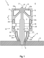
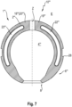
- FIG. 1 shows a first embodiment of a feeder insert 1 according to the invention, which is used in the casting of metals in a casting mold (not shown in detail).
- the feeder insert 1 comprises a feeder body 2, which defines a feeder cavity 4 for receiving liquid metal.
- the feeder body 2 has a first end 6 with a passage opening 8 for the liquid metal.
- the feeder body 2 further has a second end 10, which is opposite the first end 6, wherein the second end 10 of the feeder body 2 is closed.
- a centering pin 12 is inserted into the feeder body 2, which is arranged on a model plate 14 or a mold model.
- the centering pin 12 serves to ensure the exact position of the feeder insert 1.
- the centering pin 12 is not part of the feeder insert 1 itself, but merely serves to position the feeder insert 1 during mold production and is removed after the production of at least one mold part of the casting mold.
- a centering tip 16 of the centering pin 12 extends in the Figure 1 shown embodiment through the second end 10 of the feeder body 2, although this is not absolutely necessary, but the centering mandrel 12 with its centering tip 16 can also end within the feeder body 2.
- the feeder insert 1 or the feeder body 2 is thus divided vertically and each of the feeder shells 18, 20 can be manufactured individually and separately. In this way, even complex shapes such as in Figure 1
- the feeder cavity 4 of the Figure 1 The embodiment shown has an undercut, which is characterized in that the feeder cavity 4 initially widens from the through-opening 8 and then tapers again towards the second end 10. In order to produce such a feeder cavity 4 in a one-piece feeder body 2, it would be necessary to work with a lost core in the interior. Alternatively, such a feeder cavity 4 would have to be produced by means of a lift-off manufacturing process.
- such a shape has been formed by the feeder body 2 being divided horizontally, namely consisting of a lower feeder part and a top feeder part, which can be separated from one another in the vertical direction. Nevertheless, even with the conventional method of operation Restrictions in geometry that no longer exist due to the existing vertical division.
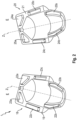
- the first feeder shell 18 has a first dividing surface 19, and the second feeder shell 20 has a second dividing surface 21.
- the first and second dividing surfaces 19, 21 are designed to abut one another when the feeder shells 18, 20 are assembled.
- Three projections are provided on the first dividing surface 19 of the first feeder shell 18: a first projection 22a, a further first projection 22b, and a third first projection 22c.
- the first dividing surface 19 of the first feeder shell 18 also has a first recess 23a, a further first recess 23b, and a third first recess 23c.
- the second feeder shell 20 or the second dividing surface 21 corresponds to the first feeder shell 18 or the first dividing surface 19 and has a second projection 24a, a further second projection 24b, and a third second projection 24c. It also has a second recess 25a, a further second recess 25b, and a third second recess 25c.
- the projections and recesses of the two feeder shells 18, 20 can interact.
- the first projection 22a enters the second recess 25a
- the second projection 24a enters the first recess 23a.
- the projection 22c enters the recess 25c
- the projection 24c enters the recess 23c
- the projection 22b enters the recess 25b
- the projection 24b enters the recess 23b.
- the first and second feeder shells 18, 20 of the first embodiment are further characterized by the fact that the feeder shells 18, 20 are identically designed. This can be achieved through the clever arrangement of the projections and recesses. This allows identical parts to be used, and the feeder shells 18, 20 can be manufactured in the same core shooters.
- a retaining collar 26 is also provided.
- the retaining collar 26 is accommodated in a circumferential recess 28 in order to fix the retaining collar 26 in the axial position.
- this recess 28 is not required and in the Figure 2
- the retaining sleeve 26 can be made, for example, from paper, rubber, elastomer material, metal, or other materials.
- the retaining sleeve 26 It is not necessary for the retaining sleeve 26 to absorb particularly high forces; rather, it serves to prevent the first and second feeder shells 18, 20 from falling apart during transport or positioning on the model plate 14.
- the retaining sleeve 26 is made from a material that burns completely during the casting process. In this way, the molding sand surrounding the feeder insert 1 can be kept free of residues of other materials.
- the various projections 22a - 22c, 24a - 24c, and recesses 23a - 23c, 25a - 25c, are arranged on the first and second dividing surfaces 19, 21 in such a way that a distance A between adjacent ones of these elements (cf. Figure 1 ) is not greater than a predetermined value, namely preferably not greater than 20 mm. The shorter this distance, the better, in order to avoid so-called springs.
- liquid metal entering the feeder cavity 4 through the passage opening 8 could flow between the parting surfaces 19, 21 and there radially through them towards the outside of the feeder insert 1.
- the interlacing of the projections and recesses forms a certain barrier.
- the feeder insert 1 is designed as a so-called telefeeder and has a weakened area 30 at which the feeder body 2 can break and be compressed. This is particularly important with reference to the Figures 3a, 3b shown.
- the feeder body 2 has a base section 32 and a cap section 34, which are separated from each other by the weakened area 30.
- the weakened area 30 is designed as a section with reduced wall thickness, as can easily be seen from the Figures 1 - 3b can be seen.
- the base section 32 has a first outer diameter D1 which is equal to or smaller than a second diameter D2, namely the inner diameter of the feeder cavity 4 in the region of the cap section 34. In this way, when the weakened region 30 breaks, the base section 32 can dip into the cap section 34.
- the base section 32 is also slightly conical. It tapers toward the passage opening 8 on both its outer surface 38 and its inner surface 40. This creates a constriction so that the solidified metal located in the feeder cavity 4 after the completion of the casting process can be easily removed.
- the taper thus serves to create a notch with a notch effect. Furthermore, the taper, particularly the taper on the outer surface 38, results in a smaller footprint for the feeder insert 1.
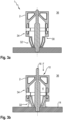
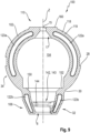
- FIGS. 4a, 4b show a second embodiment of the present invention.
- the feeder insert 1' has a feeder body 2', which defines a feeder cavity 4' for receiving liquid metal.
- Identical and similar elements are provided with reference numerals, which are preceded by an apostrophe for the second embodiment. The differences from the first embodiment are particularly highlighted below.
- the feeder cavity 4' is partially spherical.
- the feeder body 2' is again made of two Feeder bowls 18', 20' are formed, of which in the Figures 4a, 4b but only one feeder shell 18' is shown.
- the second feeder shell 20' is again formed identically to the first feeder shell 18'. This can be clearly seen from the first projection 22a', the further first projection 22b', as well as the first recess 23a' and the further first recess 23b'.
- the feeder body 2' differs in its geometry from that of the first embodiment ( Figures 1 - 3b ) in particular in that the cap section 34 of the feeder body 2' is also substantially partially spherical. Accordingly, the first projection 22a' and the first recess 23a' are also partially circular or arcuate.
- the feeder insert 1' according to the second embodiment ( Figures 4a, 4b ) is designed as a telefeeder and has a weakening area 30, which is similar in function to that of the first embodiment ( Figures 1 - 3b ) corresponds.
- a spherical shape is a particularly preferred shape because a sphere has a particularly favorable surface-to-volume ratio. This allows the temperature of the metal contained in the feeder cavity 4 to be maintained high, and the metal remains liquid for a longer period than with other geometries.
- the feeder body 2' of the second embodiment ( Figures 4a - 4b ) has an undercut, and the feeder cavity 4' initially widens from the passage opening 8 in the direction of the second end 10' along the central axis Z and then tapers again.
- the spherical shape is a particularly complex shape to produce for feeders and is particularly preferred within the scope of the invention because it can be manufactured easily and economically due to the two feeder shells 18', 20'.
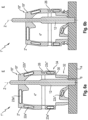
- FIG. 5a A third in the Figures 5a, 5b
- the embodiment shown is essentially based on the second one shown in the Figures 4a and 4b illustrated embodiment, so that in the following the differences to the second embodiment ( Figure 4a, 4b ) are highlighted.
- a metallic attachment 42 is provided, which is arranged around the passage opening 8 and has a collar 44 extending axially in the direction of the central axis Z.
- the metallic attachment 42 covers the conical region of the outer surface 38, but not a cylindrical part 39 with the first diameter D1.
- the cylindrical part 39 should, in case of breakage of the weakened area 30, dip into the cap section 34 of the feeder body 2' (as in Figure 5b shown), so that it is advantageous if the metallic attachment 42 is not arranged here.
- the projecting collar 44 serves to hold the feeder body 2' slightly away from the pattern plate 14 and at the same time to reduce the standing area.
- the inner diameter of the collar 44 essentially corresponds to the outer diameter of the centering mandrel 12. Otherwise, the feeder body 2' corresponds to that of the third embodiment ( Figures 4a, 4b ).
- the metallic attachment 42 which is preferably made in one piece, preferably completely encloses the conical section of the base section 42 radially and thus also provides further support for the two feeder shells 18', 20' and thus supports the function of the retaining sleeve 26.
- FIG. 6a, 6b A so-called side feeder is shown, which is used to be attached to the side of a casting mold.
- the first and second feeder shells 18", 20" cannot be formed identically, as was the case in the previous embodiments, which is easily apparent from the Figures 6a, 6b Rather, the feeder shells 18", 20" must be designed essentially mirror-symmetrically along the parting plane E, with projections and recesses being complementary to each other.
- the first feeder shell 18" again has a first dividing surface 19" on which a first projection 22a", a further first projection 22b", and a third first projection 22c" are formed.
- first and second feeder shells 18", 20" are arranged in a clockwise or counterclockwise direction, alternating with a first recess 23a", a further first recess 23b", and a third first recess 23c".
- the alternating arrangement of the projection and recess leads to a better connection of the first and second feeder shells 18", 20".
- a retaining sleeve 26 is also provided, although this is not absolutely necessary, and the feeder shells 18", 20" can also be connected, for example, by means of an adhesive.
- the feeder insert 1 which is designed as a side feeder, is also designed in this case as a so-called telefeeder. It also has a weakened area 30 as well as a base section 32 and a cap section 34, wherein again an outer diameter of the base section 32 is smaller than or equal to the inner diameter of the cap section 34.
- Figure 6b shows a compressed representation in which the cap section 34 has been shifted downwards relative to the base section 32 and the weakened area 30 has already broken.
- a centering mandrel 12 is also provided in this embodiment, which also serves to hold the feeder insert 1" designed as a side feeder on the pattern plate 14.
- the geometry of the feeder cavity 4" is very complex.
- this complex geometry can be produced simply and cost-effectively.
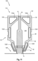
- FIG. 7 now shows a feeder insert 1′′′ in a fifth embodiment.
- This feeder insert 1′′′ is essentially based on the feeder insert according to the second and third embodiments ( Fig. 4a to 5b ), wherein the feeder insert 1′′′ according to the fifth embodiment, in contrast to the second and third embodiments, is not designed as a telescopic feeder. For this reason, it has no base section, but merely a feeder body 2′′′, which essentially corresponds to the cap section according to the second and third embodiments.
- a first and second feeder shell 18"', 20′′′ (only the feeder shell 18′′′ in Figure 7 shown), which comprises a first dividing surface 19′′′ with a projection 22′′′ and a recess 23′′′. It can be referred to as a spherical feeder and has a spherical or partially spherical feeder cavity 4′′′'.
- the first and second feeder shells 18′′′, 20′′′ according to the fifth embodiment can again be identical to one another.
- a recess 28 is also provided for a retaining sleeve (not shown).
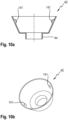
- a first difference to the embodiment of the Fig. 5a, 5b lies in the fact that the feeder body 102 according to Fig. 8 and 9 is intended to be connected to the metallic attachment 42 as shown in the Figures 10a, 10b
- the metallic attachment 42 has, in the Fig. 10a, 10b
- the embodiment shown has first locking elements 141, which here are in the form of projections or noses. These can be incorporated directly during the deep-drawing manufacturing process of the metallic attachment 42.
- the feeder body 102 has corresponding second locking elements 142, here in the form of an L-shaped groove 143.
- the first locking element 141 of the metallic attachment 42 can interact with this in the manner of a bayonet closure.
- the metallic attachment 42 is initially placed axially from below onto the assembled feeder shells 118, 120, with the first locking elements 141 entering the sections of the groove 143 aligned parallel to the central axis Z.
- the metallic attachment 42 must then be rotated about the central axis Z, clockwise in the embodiment shown.
- a constriction 144 is preferably provided in the groove 143, narrowing the cross-section in front of one end of the groove 143.
- the first locking element 141 can then be pushed over the constriction 144, applying force, and move behind it in the direction of movement, thus securing the metallic attachment 42 against reverse rotation. This prevents it from getting lost during transport.
- an insertion chamfer 17 is provided on the recess 15 for the centering mandrel tip 16. This serves to ensure that when the feeder insert 100 is placed on a centering mandrel 12, the tip does not strike the ceiling of the feeder cavity 104 and prevent pieces from breaking off.
- the material of the feeder body 102 is preferably exothermic, and fragments thereof can contaminate liquid metal entering the feeder cavity 104, which can lead to deteriorated component quality.
- the insertion chamfer preferably provided here therefore serves to improve the component quality of a cast component.
- a bevel 150 is also provided in the lower region of the feeder body 102, specifically on the base section 32. Tests have shown that in a variant as shown in the Figures 4a to 5b shown, which do not have such a bevel, material breaking out of the ceiling can remain on the annular shoulder 152 of the base section 32. This As described above, material can then negatively impact the component quality during the subsequent casting process.
- the chamfer 150 serves to ensure that any material that breaks out can fall toward the through-hole 8 and can then be removed from the feeder cavity 104 when the centering mandrel 12 is withdrawn. The chamfer 150 thus also serves to improve the component quality.
- the Fig. 8 , 9 It is provided that an area of the cap section 34, opposite the through-opening 8, is flattened and has a flat surface 160.
- the flat surface 160 serves to allow the feeder insert 100 to be placed on a support during transport. This simplifies transport and handling.
- Figure 11 shows a seventh embodiment based on the embodiment of the Fig. 3a, 3b based, but additionally the metallic attachment 42 according to Fig. 10a, 10b uses.
Landscapes
- Engineering & Computer Science (AREA)
- Mechanical Engineering (AREA)
- Molds, Cores, And Manufacturing Methods Thereof (AREA)
Applications Claiming Priority (2)
| Application Number | Priority Date | Filing Date | Title |
|---|---|---|---|
| DE102021104435.9A DE102021104435A1 (de) | 2021-02-24 | 2021-02-24 | Vertikal geteilter Speiser zur Verwendung beim Gießen von Metallen in Gießformen sowie Verfahren zu dessen Herstellung |
| PCT/EP2022/054539 WO2022180103A1 (de) | 2021-02-24 | 2022-02-23 | Vertikal geteilter speiser zur verwendung beim giessen von metallen in giessformen sowie verfahren zu dessen herstellung |
Publications (3)
| Publication Number | Publication Date |
|---|---|
| EP4297920A1 EP4297920A1 (de) | 2024-01-03 |
| EP4297920B1 true EP4297920B1 (de) | 2025-03-12 |
| EP4297920C0 EP4297920C0 (de) | 2025-03-12 |
Family
ID=80738828
Family Applications (1)
| Application Number | Title | Priority Date | Filing Date |
|---|---|---|---|
| EP22710009.6A Active EP4297920B1 (de) | 2021-02-24 | 2022-02-23 | Vertikal geteilter speiser zur verwendung beim giessen von metallen in giessformen sowie verfahren zu dessen herstellung |
Country Status (10)
| Country | Link |
|---|---|
| US (2) | US12151281B2 (pl) |
| EP (1) | EP4297920B1 (pl) |
| JP (1) | JP2024509094A (pl) |
| KR (1) | KR20230148342A (pl) |
| CN (1) | CN116917061A (pl) |
| DE (1) | DE102021104435A1 (pl) |
| ES (1) | ES3026122T3 (pl) |
| MX (1) | MX2023009894A (pl) |
| PL (1) | PL4297920T3 (pl) |
| WO (1) | WO2022180103A1 (pl) |
Families Citing this family (1)
| Publication number | Priority date | Publication date | Assignee | Title |
|---|---|---|---|---|
| DE202021106147U1 (de) * | 2021-11-10 | 2022-11-14 | Ask Chemicals Gmbh | Speiser |
Citations (1)
| Publication number | Priority date | Publication date | Assignee | Title |
|---|---|---|---|---|
| EP1775045B1 (de) * | 2005-10-14 | 2010-03-03 | Hofmann Ceramic GmbH | Speisereinsatz für eine Giessform |
Family Cites Families (13)
| Publication number | Priority date | Publication date | Assignee | Title |
|---|---|---|---|---|
| DE2428885A1 (de) * | 1974-06-14 | 1976-01-02 | Eduard Dr Ing Baur | Blinder, verlorener kopf fuer giessformen |
| GB9113121D0 (en) | 1991-06-18 | 1991-08-07 | Foseco Int | Vertically parted mould having a feeder unit therein |
| DE10039519B4 (de) | 2000-08-08 | 2007-05-31 | Chemex Gmbh | Speisereinsatz |
| DE102006055988A1 (de) * | 2006-11-24 | 2008-05-29 | Chemex Gmbh | Speisereinsatz und Speiserelement |
| CN201136039Y (zh) * | 2007-12-27 | 2008-10-22 | 济南圣泉集团股份有限公司 | 一种组合式铸造用冒口套 |
| EP2659996B1 (en) * | 2012-04-30 | 2015-04-15 | Foseco International Limited | Feeder sleeve |
| CN103624208A (zh) * | 2012-08-25 | 2014-03-12 | 天津湶钰冒口有限公司 | 铸造用冒口热芯盒成型技术工艺 |
| DE102013209775B3 (de) | 2013-05-27 | 2014-10-23 | Chemex Gmbh | Speisereinsatz |
| GB201415516D0 (en) | 2014-09-02 | 2014-10-15 | Foseco Int | Feeder system |
| CN204672906U (zh) * | 2015-06-01 | 2015-09-30 | 天津凯星科技有限公司 | 一种拼接组合式冒口套 |
| DE102015115437A1 (de) * | 2015-09-14 | 2017-03-16 | GTP Schäfer Gießtechnische Produkte GmbH | Verfahren zur Herstellung eines Speisers in einer Kernschießmaschine und zur Durchführung des Verfahrens geeigneter Kernkasten |
| CN110153376A (zh) * | 2019-06-18 | 2019-08-23 | 莒南县友园机械有限公司 | 一种新型发热冒口 |
| DE202021106147U1 (de) * | 2021-11-10 | 2022-11-14 | Ask Chemicals Gmbh | Speiser |
-
2021
- 2021-02-24 DE DE102021104435.9A patent/DE102021104435A1/de active Pending
-
2022
- 2022-02-23 CN CN202280016743.0A patent/CN116917061A/zh active Pending
- 2022-02-23 JP JP2023551687A patent/JP2024509094A/ja active Pending
- 2022-02-23 ES ES22710009T patent/ES3026122T3/es active Active
- 2022-02-23 EP EP22710009.6A patent/EP4297920B1/de active Active
- 2022-02-23 PL PL22710009.6T patent/PL4297920T3/pl unknown
- 2022-02-23 KR KR1020237031993A patent/KR20230148342A/ko active Pending
- 2022-02-23 US US18/547,376 patent/US12151281B2/en active Active
- 2022-02-23 MX MX2023009894A patent/MX2023009894A/es unknown
- 2022-02-23 WO PCT/EP2022/054539 patent/WO2022180103A1/de not_active Ceased
-
2024
- 2024-07-15 US US18/772,954 patent/US20250010359A1/en active Pending
Patent Citations (1)
| Publication number | Priority date | Publication date | Assignee | Title |
|---|---|---|---|---|
| EP1775045B1 (de) * | 2005-10-14 | 2010-03-03 | Hofmann Ceramic GmbH | Speisereinsatz für eine Giessform |
Also Published As
| Publication number | Publication date |
|---|---|
| US20240123493A1 (en) | 2024-04-18 |
| US20250010359A1 (en) | 2025-01-09 |
| DE102021104435A1 (de) | 2022-08-25 |
| MX2023009894A (es) | 2023-09-04 |
| CN116917061A (zh) | 2023-10-20 |
| PL4297920T3 (pl) | 2025-06-23 |
| WO2022180103A1 (de) | 2022-09-01 |
| EP4297920C0 (de) | 2025-03-12 |
| JP2024509094A (ja) | 2024-02-29 |
| ES3026122T3 (en) | 2025-06-10 |
| KR20230148342A (ko) | 2023-10-24 |
| EP4297920A1 (de) | 2024-01-03 |
| US12151281B2 (en) | 2024-11-26 |
Similar Documents
| Publication | Publication Date | Title |
|---|---|---|
| DE10039519B4 (de) | Speisereinsatz | |
| EP1345716B1 (de) | Speiser mit einem rohrähnlichen körper | |
| EP3003601B1 (de) | Speisereinsatz, formelement für den speisereinsatz und verfahren zum giessen von metall unter verwendung derselben | |
| EP2982458B1 (de) | Anordnung zur verwendung beim herstellen einer teilbaren giessform | |
| EP0241009A2 (de) | Verfahren und Formwerkzeug zur Herstellung eines in ein Mauerwerk einsetzbaren Steigbügels | |
| DE102005008324A1 (de) | Speiser mit beweglicher Tülle | |
| EP3056297B1 (de) | Verwendung eines speisereinsatzes und verfahren zum herstellen einer giessform mit vertikaler formteilung | |
| EP4297920B1 (de) | Vertikal geteilter speiser zur verwendung beim giessen von metallen in giessformen sowie verfahren zu dessen herstellung | |
| WO2005095020A2 (de) | Speiser mit verformbarer tülle | |
| EP2956256B1 (de) | Speisereinsatz und verfahren zu dessen anordnung in einer giessform | |
| EP2511067B1 (de) | Kühlhülse mit Stützelement | |
| EP3727723A1 (de) | Verfahren zum herstellen eines formteils sowie speisereinsatz zur verwendung in einem solchen verfahren | |
| DE3047621A1 (de) | "formeinlass, der die einleitung einer steifen formmasse in einen formraum zulaesst" | |
| DE10142357B4 (de) | Speiser mit einem rohrähnlichen Körper | |
| EP3927483A1 (de) | EINTEILIGER SPEISERKÖRPER ZUR VERWENDUNG BEIM GIEßEN VON METALLEN | |
| DE840905C (de) | Spritzgiessform | |
| EP3917698B1 (de) | Einteiliger speiserkörper zur verwendung beim giessen von metallen | |
| DE102010022834A1 (de) | Federdorn und Gießmodell mit Federdorn | |
| EP2532500B1 (de) | Verfahren und Vorrichtung zur Herstellung von Keramikartikeln | |
| EP1232050B1 (de) | Kernausschmelzverfahren zur herstellung einer hohlraumstruktur | |
| DE10334855B3 (de) | Verfahren und Vorrichtung zur Positionierung metallischer Teile in oder an Gießereikernen und Gießformen | |
| DE102016100970A1 (de) | Verfahren zum Herstellen eines Kunststoffbauteils und Kunststoffbauteil | |
| DE202017103989U1 (de) | Speisersystem | |
| DE102022106807A1 (de) | Speiser und Speisersystem für Gießformen | |
| EP3405324A1 (de) | Verfahren zum spritzgiessen eines kunststoffbauteils und kunststoffbauteil |
Legal Events
| Date | Code | Title | Description |
|---|---|---|---|
| STAA | Information on the status of an ep patent application or granted ep patent |
Free format text: STATUS: UNKNOWN |
|
| STAA | Information on the status of an ep patent application or granted ep patent |
Free format text: STATUS: THE INTERNATIONAL PUBLICATION HAS BEEN MADE |
|
| PUAI | Public reference made under article 153(3) epc to a published international application that has entered the european phase |
Free format text: ORIGINAL CODE: 0009012 |
|
| STAA | Information on the status of an ep patent application or granted ep patent |
Free format text: STATUS: REQUEST FOR EXAMINATION WAS MADE |
|
| 17P | Request for examination filed |
Effective date: 20230925 |
|
| AK | Designated contracting states |
Kind code of ref document: A1 Designated state(s): AL AT BE BG CH CY CZ DE DK EE ES FI FR GB GR HR HU IE IS IT LI LT LU LV MC MK MT NL NO PL PT RO RS SE SI SK SM TR |
|
| DAV | Request for validation of the european patent (deleted) | ||
| DAX | Request for extension of the european patent (deleted) | ||
| GRAP | Despatch of communication of intention to grant a patent |
Free format text: ORIGINAL CODE: EPIDOSNIGR1 |
|
| STAA | Information on the status of an ep patent application or granted ep patent |
Free format text: STATUS: GRANT OF PATENT IS INTENDED |
|
| INTG | Intention to grant announced |
Effective date: 20241126 |
|
| GRAS | Grant fee paid |
Free format text: ORIGINAL CODE: EPIDOSNIGR3 |
|
| GRAA | (expected) grant |
Free format text: ORIGINAL CODE: 0009210 |
|
| STAA | Information on the status of an ep patent application or granted ep patent |
Free format text: STATUS: THE PATENT HAS BEEN GRANTED |
|
| AK | Designated contracting states |
Kind code of ref document: B1 Designated state(s): AL AT BE BG CH CY CZ DE DK EE ES FI FR GB GR HR HU IE IS IT LI LT LU LV MC MK MT NL NO PL PT RO RS SE SI SK SM TR |
|
| REG | Reference to a national code |
Ref country code: GB Ref legal event code: FG4D Free format text: NOT ENGLISH |
|
| REG | Reference to a national code |
Ref country code: CH Ref legal event code: EP |
|
| REG | Reference to a national code |
Ref country code: DE Ref legal event code: R096 Ref document number: 502022003184 Country of ref document: DE |
|
| REG | Reference to a national code |
Ref country code: IE Ref legal event code: FG4D Free format text: LANGUAGE OF EP DOCUMENT: GERMAN |
|
| U01 | Request for unitary effect filed |
Effective date: 20250404 |
|
| U07 | Unitary effect registered |
Designated state(s): AT BE BG DE DK EE FI FR IT LT LU LV MT NL PT RO SE SI Effective date: 20250411 |
|
| REG | Reference to a national code |
Ref country code: ES Ref legal event code: FG2A Ref document number: 3026122 Country of ref document: ES Kind code of ref document: T3 Effective date: 20250610 |
|
| PG25 | Lapsed in a contracting state [announced via postgrant information from national office to epo] |
Ref country code: RS Free format text: LAPSE BECAUSE OF FAILURE TO SUBMIT A TRANSLATION OF THE DESCRIPTION OR TO PAY THE FEE WITHIN THE PRESCRIBED TIME-LIMIT Effective date: 20250612 |
|
| PG25 | Lapsed in a contracting state [announced via postgrant information from national office to epo] |
Ref country code: NO Free format text: LAPSE BECAUSE OF FAILURE TO SUBMIT A TRANSLATION OF THE DESCRIPTION OR TO PAY THE FEE WITHIN THE PRESCRIBED TIME-LIMIT Effective date: 20250612 |
|
| PG25 | Lapsed in a contracting state [announced via postgrant information from national office to epo] |
Ref country code: HR Free format text: LAPSE BECAUSE OF FAILURE TO SUBMIT A TRANSLATION OF THE DESCRIPTION OR TO PAY THE FEE WITHIN THE PRESCRIBED TIME-LIMIT Effective date: 20250312 |
|
| PG25 | Lapsed in a contracting state [announced via postgrant information from national office to epo] |
Ref country code: GR Free format text: LAPSE BECAUSE OF FAILURE TO SUBMIT A TRANSLATION OF THE DESCRIPTION OR TO PAY THE FEE WITHIN THE PRESCRIBED TIME-LIMIT Effective date: 20250613 |
|
| PG25 | Lapsed in a contracting state [announced via postgrant information from national office to epo] |
Ref country code: SM Free format text: LAPSE BECAUSE OF FAILURE TO SUBMIT A TRANSLATION OF THE DESCRIPTION OR TO PAY THE FEE WITHIN THE PRESCRIBED TIME-LIMIT Effective date: 20250312 |
|
| PG25 | Lapsed in a contracting state [announced via postgrant information from national office to epo] |
Ref country code: SK Free format text: LAPSE BECAUSE OF FAILURE TO SUBMIT A TRANSLATION OF THE DESCRIPTION OR TO PAY THE FEE WITHIN THE PRESCRIBED TIME-LIMIT Effective date: 20250312 |
|
| PG25 | Lapsed in a contracting state [announced via postgrant information from national office to epo] |
Ref country code: IS Free format text: LAPSE BECAUSE OF FAILURE TO SUBMIT A TRANSLATION OF THE DESCRIPTION OR TO PAY THE FEE WITHIN THE PRESCRIBED TIME-LIMIT Effective date: 20250712 |