EP4297910B1 - Reservoir sowie fluidabgabevorrichtung - Google Patents
Reservoir sowie fluidabgabevorrichtung Download PDFInfo
- Publication number
- EP4297910B1 EP4297910B1 EP22710671.3A EP22710671A EP4297910B1 EP 4297910 B1 EP4297910 B1 EP 4297910B1 EP 22710671 A EP22710671 A EP 22710671A EP 4297910 B1 EP4297910 B1 EP 4297910B1
- Authority
- EP
- European Patent Office
- Prior art keywords
- basket
- insert
- fluid product
- advantageously
- product reservoir
- Prior art date
- Legal status (The legal status is an assumption and is not a legal conclusion. Google has not performed a legal analysis and makes no representation as to the accuracy of the status listed.)
- Active
Links
Images


Classifications
-
- B—PERFORMING OPERATIONS; TRANSPORTING
- B05—SPRAYING OR ATOMISING IN GENERAL; APPLYING FLUENT MATERIALS TO SURFACES, IN GENERAL
- B05B—SPRAYING APPARATUS; ATOMISING APPARATUS; NOZZLES
- B05B11/00—Single-unit hand-held apparatus in which flow of contents is produced by the muscular force of the operator at the moment of use
- B05B11/0005—Components or details
- B05B11/0037—Containers
- B05B11/0039—Containers associated with means for compensating the pressure difference between the ambient pressure and the pressure inside the container, e.g. pressure relief means
- B05B11/0044—Containers associated with means for compensating the pressure difference between the ambient pressure and the pressure inside the container, e.g. pressure relief means compensating underpressure by ingress of atmospheric air into the container, i.e. with venting means
- B05B11/00442—Containers associated with means for compensating the pressure difference between the ambient pressure and the pressure inside the container, e.g. pressure relief means compensating underpressure by ingress of atmospheric air into the container, i.e. with venting means the means being actuated by the difference between the atmospheric pressure and the pressure inside the container
-
- B—PERFORMING OPERATIONS; TRANSPORTING
- B05—SPRAYING OR ATOMISING IN GENERAL; APPLYING FLUENT MATERIALS TO SURFACES, IN GENERAL
- B05B—SPRAYING APPARATUS; ATOMISING APPARATUS; NOZZLES
- B05B11/00—Single-unit hand-held apparatus in which flow of contents is produced by the muscular force of the operator at the moment of use
- B05B11/0005—Components or details
- B05B11/0008—Sealing or attachment arrangements between sprayer and container
-
- B—PERFORMING OPERATIONS; TRANSPORTING
- B05—SPRAYING OR ATOMISING IN GENERAL; APPLYING FLUENT MATERIALS TO SURFACES, IN GENERAL
- B05B—SPRAYING APPARATUS; ATOMISING APPARATUS; NOZZLES
- B05B11/00—Single-unit hand-held apparatus in which flow of contents is produced by the muscular force of the operator at the moment of use
- B05B11/0005—Components or details
- B05B11/0037—Containers
- B05B11/0039—Containers associated with means for compensating the pressure difference between the ambient pressure and the pressure inside the container, e.g. pressure relief means
- B05B11/0044—Containers associated with means for compensating the pressure difference between the ambient pressure and the pressure inside the container, e.g. pressure relief means compensating underpressure by ingress of atmospheric air into the container, i.e. with venting means
- B05B11/00444—Containers associated with means for compensating the pressure difference between the ambient pressure and the pressure inside the container, e.g. pressure relief means compensating underpressure by ingress of atmospheric air into the container, i.e. with venting means with provision for filtering or cleaning the air flow drawn into the container
-
- B—PERFORMING OPERATIONS; TRANSPORTING
- B05—SPRAYING OR ATOMISING IN GENERAL; APPLYING FLUENT MATERIALS TO SURFACES, IN GENERAL
- B05B—SPRAYING APPARATUS; ATOMISING APPARATUS; NOZZLES
- B05B11/00—Single-unit hand-held apparatus in which flow of contents is produced by the muscular force of the operator at the moment of use
- B05B11/0005—Components or details
- B05B11/0037—Containers
- B05B11/0054—Cartridges, i.e. containers specially designed for easy attachment to or easy removal from the rest of the sprayer
-
- B—PERFORMING OPERATIONS; TRANSPORTING
- B05—SPRAYING OR ATOMISING IN GENERAL; APPLYING FLUENT MATERIALS TO SURFACES, IN GENERAL
- B05B—SPRAYING APPARATUS; ATOMISING APPARATUS; NOZZLES
- B05B11/00—Single-unit hand-held apparatus in which flow of contents is produced by the muscular force of the operator at the moment of use
- B05B11/0005—Components or details
- B05B11/0089—Dispensing tubes
-
- B—PERFORMING OPERATIONS; TRANSPORTING
- B05—SPRAYING OR ATOMISING IN GENERAL; APPLYING FLUENT MATERIALS TO SURFACES, IN GENERAL
- B05B—SPRAYING APPARATUS; ATOMISING APPARATUS; NOZZLES
- B05B11/00—Single-unit hand-held apparatus in which flow of contents is produced by the muscular force of the operator at the moment of use
- B05B11/01—Single-unit hand-held apparatus in which flow of contents is produced by the muscular force of the operator at the moment of use characterised by the means producing the flow
- B05B11/10—Pump arrangements for transferring the contents from the container to a pump chamber by a sucking effect and forcing the contents out through the dispensing nozzle
- B05B11/1042—Components or details
- B05B11/1043—Sealing or attachment arrangements between pump and container
- B05B11/1046—Sealing or attachment arrangements between pump and container the pump chamber being arranged substantially coaxially to the neck of the container
- B05B11/1047—Sealing or attachment arrangements between pump and container the pump chamber being arranged substantially coaxially to the neck of the container the pump being preassembled as an independent unit before being mounted on the container
-
- B—PERFORMING OPERATIONS; TRANSPORTING
- B05—SPRAYING OR ATOMISING IN GENERAL; APPLYING FLUENT MATERIALS TO SURFACES, IN GENERAL
- B05B—SPRAYING APPARATUS; ATOMISING APPARATUS; NOZZLES
- B05B15/00—Details of spraying plant or spraying apparatus not otherwise provided for; Accessories
- B05B15/30—Dip tubes
Definitions
- the present invention relates to a fluid product reservoir comprising a container defining a neck and a mounting part mounted on the neck.
- the mounting part forms a basket disposed at the neck and a dip tube which extends from the basket into the container.
- the dip tube is initially sealed by a sealing member, which may be in the form of a membrane to be pierced, a plug to be dislodged, etc.
- This type of reservoir is often used as a refill on which a top assembly comprising a pump or a valve is removably mounted, so that it can be removed from a reservoir to be refitted on a new reservoir.
- the preferred fields of application of the present invention are those of cosmetics, food, household products and even pharmacy.
- the present invention aims to overcome this problem related to the clearance of the dip tube.
- Another aim of the invention is to be able to use a standard dispensing member to cause the piercing or movement of a sealing member in the dip tube.
- the present invention provides a fluid product reservoir which further comprises an insert arranged in the basket and comprising a piercing element movable between an initial position in which the sealing member is closing and a final position in which the sealing member is moved into a state passing through the piercing element.
- an insert arranged in the basket and comprising a piercing element movable between an initial position in which the sealing member is closing and a final position in which the sealing member is moved into a state passing through the piercing element.
- the insert is mainly housed inside the basket and comprises a sleeve forming a housing for receiving the fitting of an inlet sleeve of a dispensing member (pump or valve), the sleeve being integral in movement with the piercing element.
- the housing and the piercing element constitute a sort of extension for the inlet sleeve, but this extension is part of the reservoir and not of the dispensing member.
- the insert is integral with the basket in the initial position and in the final position. It can even be said that the insert is permanently integral with the basket, even if its piercing element is moved in the basket by the inlet sleeve of the dispensing member which is received in the receiving housing.
- the basket and the insert may delimit between them a buffer space, which advantageously communicates with the outside in the final position of the insert and which advantageously communicates with the container through a one-way valve or a filter allowing air from the buffer space to enter the container.
- the buffer space may be isolated from the outside in the initial position.
- the mounting part may comprise a fixing socket for mounting a member of distribution, such as a pump, comprising an inlet sleeve and a fixing ring adapted to engage with the fixing sleeve.
- This fixing sleeve is preferably threaded, as is the fixing ring, so that the displacement or piercing of the sealing member by the piercing element and/or the fitting of the inlet sleeve into the receiving housing takes place when the ring is screwed onto the sleeve.
- the insert can be slidably mounted in the basket between the initial and final positions, the insert being advantageously in sealed contact with the basket in the initial position and advantageously in non-sealing contact with the basket in the final position.
- the insert can comprise a sliding lip which is in sealed contact with a cylindrical wall of the basket in the initial position, can then slide in a sealed manner in the cylindrical wall, this cylindrical wall being able to form a relief (hollow or protruding) which will generate a sealing defect in the final position.
- the insert may comprise a deformable membrane connecting the piercing element to a fixed edge secured to the basket, the insert being advantageously made in a single piece with the mounting part.
- the basket and the insert may be molded flat side by side, being connected by a hinge or a flexible connection: the insert is then pivoted into the basket.
- the fixed edge of the insert is snapped onto the basket.
- the insert can be snapped into the basket in the final position.
- a friction lock can also fulfill the function of maintaining the snap in the final position. The aim is to prevent the insert from being removed from the basket when the dispensing member is separated from the reservoir: the insert must remain in place in the basket.
- the insert may form an inlet well, which is closed by a tear-off or pierceable cover, which advantageously extends to an upper edge of the basket.
- the inlet well may be surrounded by a flat annular area which is flush with the upper edge of the basket, so that the cover may extend flat on both the flat annular area and the top edge.
- This seal does not need to be watertight, since the tank is already sealed by the sealing member. The seal simply needs to prevent dirt from entering the insert through its inlet well. It also gives an indication to the user that the tank has never been opened. The seal can remain in place, then pierced, or conversely can be removed by the user.
- the sealing member is a pierceable membrane which remains connected to the dip tube once pierced, the dip tube advantageously forming an internal shoulder under which the pierceable membrane, once pierced, is housed.
- the pierceable membrane is made in a single piece with the rest of the mounting part.
- an upper extension of the basket may form a threaded sleeve which projects beyond a fixing cup, which engages, advantageously snap-fit, around the neck of the container.
- the container may be extremely simple, for example in the form of a blown can with a neck provided with an external snap-fit profile.
- the present invention also defines a fluid product dispenser comprising a dispensing member, such as a pump, comprising an inlet sleeve and a fixing ring for fixing the dispensing member to a fluid product reservoir as defined above comprising a receiving housing for the inlet sleeve.
- a dispensing member such as a pump
- a fixing ring for fixing the dispensing member to a fluid product reservoir as defined above comprising a receiving housing for the inlet sleeve.
- the mounting part may form a fixing sleeve, the fixing ring engaging, advantageously threaded, with the fixing sleeve on an axial fixing stroke, the engagement of the inlet sleeve in the receiving housing and/or the displacement of the sealing member by the piercing element advantageously occurring during the axial fixing stroke.
- the pump or the valve is therefore in fluid communication through the insert and the dip tube, the sealing member of which has been neutralized by the displacement of the insert under the stress of the inlet sleeve.
- the sealing member may be a pierceable membrane
- the fixing ring may be a screw-on fixing ring
- the piercing element may be a section of beveled tube
- the screw-on fixing ring when screwed onto the threaded sleeve, moves the inlet sleeve and the insert over an axial screwing stroke, the section of beveled tube advantageously piercing the pierceable membrane during this axial screwing stroke.
- the spirit of the invention lies in the fact of integrating piercing or "unsealing" means into the tank, so as not to need to adapt the dispensing member, which can therefore be standard: its only function being to push, and no longer to pierce or intervene directly on the sealing means.
- the removable fixing by screwing (or bayonet) of the dispensing member on the tank of the invention makes it possible to multiply the forces to facilitate the fitting of the entry sleeve into the receiving housing and/or the piercing of the sealing member.
- An important advantage of the invention is that the dispensing member, and more particularly its inlet sleeve, can be separated from the tank in a perfectly clean state, given that only the inside of the inlet sleeve is in contact with the fluid product: the outside of the sleeve is embedded in the housing of the insert. And even in the event of a leak through the valve or the filter, the fluid product remains in the buffer space. As a result, the dispensing member can be removed from an empty tank and refitted on a new, filled tank without the risk of depositing fluid product anywhere.
- the fact of making the threaded sleeve and the sealing member (pierceable membrane) in a single part, namely the mounting part, is a feature that could be implemented regardless of whether the basket contains an insert.
- This feature is advantageous in two ways. Firstly, the axial distance between the tank thread and the pierceable membrane is constant: this is not the case in the document US10226782 . Piercing of the membrane during the screwing stroke is therefore easier to ensure. Secondly, the container can be made more simply without external thread. A protection could therefore be sought for a tank with a mounting part forming a threaded sleeve and a sealing member.
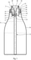
- the reservoir R comprises a container R1 comprising a neck R2 which can be provided externally with one or more attachment profile(s) R3, preferably in the form of snap-fastening profiles.
- the container R1 can very simply be produced in the form of a can. It can be obtained using a blow-molding process, given that the design of its neck R2 is very simple.
- the tank R also comprises a mounting part 1 which is preferably made by injection molding of suitable plastic material.
- the mounting part is preferably a single piece, with the exception of its single directional valve 13, as will be seen below.
- This mounting part 1 comprises a basket 11, a dip tube 12, a one-way valve 13 and a fixing cup 14.
- the basket 11, the dip tube 12 and the cup 14 can be made as a single piece. Separate embodiments are however conceivable.
- the dip tube 12 could be mounted on the basket 11.
- the dip tube 12 is connected to the lower end of the basket 11 and extends into the container R1 up to near its bottom.
- the dip tube 12 can be rigid or flexible.
- the communication between the basket 11 and the dip tube 12 is cut off by a sealing member 121, which is here arranged inside the dip tube 12, close to the basket 11.
- This sealing member 121 is here in the form of a pierceable membrane which is made in one piece with the rest of the mounting part 1. Instead of this pierceable membrane, it would also be possible to use an added cover or a part capable of being moved between a closing state and a passing state.
- the sealing member 121 is here made inside the dip tube 12, but it could also be arranged at the basket 11. The function of this sealing member is to cut off the communication between the inlet of the basket 11 and the outlet of the dip tube 12. It can be seen on the Figure 1 that the dip tube 12 extends inside the basket 11 in the form of a tubular section 122.
- the basket 11 is arranged at the neck R2: it extends downwards inside the container R1 and also upwards, forming a sleeve 113 which is externally threaded. It can be noted that the basket 11 has an overall cylindrical shape with its bottom partially closed and its upper end open.
- the fixing cup 14 extends radially outwards from the basket 11 to engage, advantageously snap-fit, with the neck R2 of the R1 container. Screw fixing can be considered, but is not preferable.
- the basket 11 also defines a seat for the one-way valve 13 which only allows the entry of outside air into the container R1. Any exit of fluid product from the container R1 through this valve 13 is prohibited.
- the reservoir R also comprises an insert 2 which is mainly housed inside the basket 11.
- the insert 2 generally has a funnel shape, with a passage section which decreases from top to bottom.
- the insert 2 comprises a piercing element 21 which is formed at the lower end of a tube 20 which is partially engaged inside the dip tube 12, or more precisely its tubular section 122.
- the piercing element 21 may be in the form of a beveled tube section, and advantageously sharpened.
- the tube 20 defines a passage conduit 22. In the initial position, as shown in the Figure 1 , the piercing element 21 is arranged close to or in contact with the sealing member 121 which closes the dip tube 12.
- the insert 2 Upstream of the tubing 20, the insert 2 forms a sleeve 23 which internally defines a receiving housing 24, the function of which will be given below. It can be noted that the sleeve 23 comprises a truncated upper part and a cylindrical lower part. The receiving housing 24 communicates directly with the passage conduit 22. Upstream of the sleeve 23, the insert 2 forms a crown 25 which is engaged inside the basket 11, at its threaded sleeve 113. This crown 25 defines an inlet well 26 which communicates directly with the receiving housing 24. It can be noted that the upper edge of the crown 25 is advantageously arranged flush with the upper edge of the threaded sleeve 113.
- a seal 28 can be glued both to the upper edge of the crown 25 and the upper edge of the sleeve 113, so as to prevent any introduction of foreign bodies or particles inside the insert 2.
- the seal 28 does not need to be fixed in a sealed manner, given that the interior of the container R1 is already isolated from the outside by the sealing member 121.
- a buffer space 10 is formed between the basket 11 and the insert 2. In the initial position, as shown in the Figure 1 , this buffer space 10 cannot communicate with the outside, due to the sealed contact of the crown 25 with the sleeve 113, and moreover the sealed application of the cover 28. On the other hand, the buffer space 10 can communicate with the inside of the container R1 through the one-way valve 13, as soon as a depression is formed inside the container R1. The air contained in the buffer space 10 can thus penetrate inside the tank R1.
- the mounting part 1 forms both the sealing member 121 and the threaded sleeve 113, so that the mutual arrangement of these two elements is fixed and precise. This is a characteristic which is independent of the fact that the basket 11 contains an insert 2.
- This distribution member P which can integrate a pump or a valve, also comprises an inlet sleeve P1, a fixing ring P2 and a pusher P3.
- the inlet sleeve P1 defines an internal conduit which communicates with the pump or valve chamber, generally through an inlet flap (not shown).
- the inlet sleeve P1 is of a completely conventional type adapted to receive a conventional dip tube by fitting it around or inside the inlet sleeve P1.
- the fixing member P2 preferably comprises an internal thread P21 whose pitch corresponds to that of the threaded sleeve 113 of the mounting part 1 of the tank according to the invention. It can be said that the dispensing member P does not include any inventive feature, and that it is therefore not critical to the invention.
- the dispensing member P has already been attached to the reservoir of the invention, with its inlet sleeve P1 which has already penetrated inside the inlet well 26 of the crown 25 by tearing or piercing the cover 28.
- the cover 28 can be removed before engaging the sleeve P1 inside the insert 2.
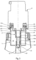
- the fixing cup 14 comprises an external skirt 141 which forms one or more snap-in teeth 144 intended to cooperate with the profiles R3 of the neck R2.
- the cup 14 also defines a self-sealing lip 142 intended to come into sealed contact with the internal wall of the neck R2 to provide a seal there.
- the threads 114 formed on the external wall of the fixing sleeve 113 which extends the basket 11 outwards can be clearly seen.
- the inner wall of the sleeve 113 is perfectly cylindrical and the crown 25 forms an annular sealing lip 251 which comes into sealed sliding contact inside the sleeve 113.
- the inner cylindrical wall 111 of the basket 11 forms one or more vertical rib(s) 1111 which thus break the cylindricity of the basket. It is then easily understood that the sliding of the insert 2 downwards will bring the annular sealing lip 251 to the level of this or these rib(s) 1111 so as to create a sealing defect. It may also be noted that the tubing 20 externally defines a snap-on bead 211 intended to engage inside a snap-on groove 123 formed inside the cylindrical section 122, which forms an extension of the dip tube 12 inside the basket 11.
- the fixing ring P2 is in its final screwing position with its thread P21 in final engagement with the thread 114 of the sleeve 113.
- the insert 2 has been moved by sliding inside the basket 11, which results in a corresponding movement of its tubing 20 inside the tubular section 122 and the dip tube 12, leading to the piercing of the sealing member 121 by the piercing element 21.
- the lip 251 of the crown 25 is then arranged at the height of the rib(s) 1111, thus creating a sealing defect.
- the snap-in rib 211 is housed inside its corresponding snap-in rib 123.
- the final mounting position is then reached.
- the buffer space 10 allows the interior of the tank R1 to communicate with the exterior through the one-way valve 13 and the sealing defect between the lip 251 and the rib 1111.
- the path of the incoming air is represented by a bubble path.
- the movement of the insert 2 inside the basket 11 takes place during the screwing phase of the ring P2 onto the sleeve 113.
- the axial movement of the insert 2 corresponds substantially to the axial screwing stroke of the dispensing member P onto the reservoir R.
- the piercing of the sealing member 21 by the piercing element 21 takes place during this axial screwing stroke.
- the fitting of the inlet sleeve P1 into the receiving housing 24 also takes place during this axial screwing stroke.
- the sealing member 121 is rendered inoperative by the piercing element 21.
- the tubing 20 ends with a section of tube that is both beveled and thinned, forming the piercing element 21.
- the dip tube 12, the section of which is preferably constant over most of its length, here comprises an inlet section 125 with reduced passage, thus forming a shoulder 124 oriented downwards.
- the sealing member 121 is in the form of a membrane which is connected to this shoulder 124.
- the membrane 121 comprises a central part 1211 of constant thickness and a thinned peripheral edge 1212 which is connected to the shoulder 124.
- this shoulder 124 makes it possible to house the membrane 121 between the piercing element 21 and the dip tube 12.
- the membrane 121 does not detach from the rest of the mounting part, and does not fall to the bottom of the dip tube 12. This avoids any risk of blockage or malfunction linked to the floating of the membrane 121.
- the mounting part 1' also includes a basket 11', a dip tube 12' and a fixing cup 14'.
- the basket 11' includes an upper annular area 114' forming a retracting rim 115.
- the basket also includes a unidirectional filter 13'.
- the insert 2' also includes a piercing element 21', a receiving housing 23' and an outer ring 25' forming a deformable flexible membrane 251'.
- the ring 25' is bordered by a fixed annular flange 252. It is then easily understood that it is possible to fold the insert 2' onto the mounting part 1' so as to cause the piercing element 21' and receiving housing 23' to penetrate inside the basket 11'. In doing so, the annular flat flange 252 will be housed inside the re-entrant rim 115 so that the ring 25' comes flush with the annular area 114' of the cup 14'.
- the fixed annular flange 252 can be snapped, preferably in a non-sealed manner, into the re-entrant rim 115.
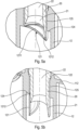
- This folded configuration is shown in the Figure 7a .
- the deformable membrane 251' is in its rest state and the piercing element 21' is away from the sealing member 121, which may be similar or identical to that of the first embodiment.
- a buffer space 10' is also formed between the basket 11' and the insert 2'.
- the fixing cup 14' externally forms a threaded fixing sleeve 113'.
- the first step is to fit the inlet sleeve P1 inside the receiving housing 23'. This is shown in the Figure 7b . Insert 2' is still in its initial state with the sealing member intact.
- the fixing of the distribution member P' on the reservoir R' has the effect of moving the inlet sleeve P1, which leads to a deformation of the membrane 251' and a movement of the piercing element 21' which then releases the sealing member 121, as shown in an enlarged manner on the figure 8 .
- the insert 2' does not slide inside the basket 11', but is however moved by deformation of its membrane 251'.
- the drilling of the sealing member 121 and/or the fitting of the sleeve input P1 in the receiving housing 23' takes place during the axial stroke of fixing the distribution member P' on the reservoir R'.
- an insert 2, 2' is an integral part of the reservoir of the invention, in the sense that it is already integrated into the reservoir, well before attaching the dispensing member to the reservoir.
- the movement of the insert under the stress of the inlet sleeve to pierce or dislodge or release the dip tube is an essential characteristic of the invention.
- the insert is permanently secured to the basket, even if its piercing element is movable in the basket.
- the formation of a buffer space 10, 10' is also advantageous, because it makes it possible to collect and trap any fluid product which could leak through the one-way valve 13, which could also be replaced by a one-way filter.
- the insert also makes it possible to maintain the dispensing member in a very satisfactory state of cleanliness, which is particularly advantageous, since the reservoir of the invention is mainly intended to serve as a refill, which implies that the dispensing member is required to be removed from an empty reservoir and then refitted onto a full reservoir.
Landscapes
- Closures For Containers (AREA)
- Containers And Packaging Bodies Having A Special Means To Remove Contents (AREA)
Claims (13)
- Reservoir (R; R') für ein Fluidprodukt, umfassend einen Behälter (R1; R1'), der einen Hals (R2) und ein Montageteil (1; 1') definiert, das auf dem Hals (R2) angebracht ist, wobei das Montageteil (1; 1') einen Korb (11; 11') bildet, der im Bereich des Halses (R2) angeordnet ist, und ein Tauchrohr (12; 12'), das sich von dem Korb (11; 11') in den Behälter (R1; R1') erstreckt, wobei das Tauchrohr (12; 12') anfänglich durch ein Versiegelungsorgan (121) verschlossen ist, wobei das Reservoir für ein Fluidprodukt (R; R') ferner einen Einsatz (2; 2') umfasst, der in dem Korb (11; 11') angeordnet ist, wobei der Einsatz (2; 2') ein Durchstechelement (21; 21') umfasst, das zwischen einer Ausgangsposition, in der das Versiegelungsorgan (121) verschließt, und einer Endposition, in der das Versiegelungsorgan (121) von dem Durchstechelement (21; 21') in einen Durchgangszustand verlagert wird, verlagerbar ist;
dadurch gekennzeichnet, dass der Einsatz (2; 2') mehrheitlich im Inneren des Korbs (11; 11') untergebracht ist und eine Manschette (23; 23') umfasst, die eine Empfangsaufnahme (24; 24') für das Einpassen einer Eingangsmuffe (P1) eines Abgabeorgans (P; P') bildet, wobei die Manschette (23; 23') mit dem Durchstechelement (21; 21') verlagerungsfest verbunden ist. - Reservoir (R; R') für ein Fluidprodukt nach Anspruch 1, wobei der Einsatz (2; 2') in der Ausgangsposition und in der Endposition fest mit dem Korb (11; 11') verbunden ist.
- Reservoir (R; R') für ein Fluidprodukt nach einem der vorhergehenden Ansprüche, wobei der Korb (11; 11') und der Einsatz (2; 2') zwischen sich einen Pufferraum (10; 10') begrenzen, der in vorteilhafter Weise in der Endposition des Einsatzes (2; 2') mit außerhalb kommuniziert und der in vorteilhafter Weise mit dem Behälter (R1; R1') über ein Einwegeventil (13; 13') kommuniziert, das die Luft aus dem Pufferraum (10; 10') in den Behälter (R1; R1') eintreten lässt.
- Reservoir (R; R') für ein Fluidprodukt nach einem der vorhergehenden Ansprüche, wobei das Montageteil (1; 1') eine Befestigungshülse (113; 113') für die Montage einer Abgabevorrichtung (P; P') wie eine Pumpe umfasst, umfassend eine Eingangsmuffe (P1) und einen Befestigungsring (P2), der geeignet ist, mit der Befestigungshülse (113; 113') in Eingriff zu kommen.
- Reservoir (R; R') für ein Fluidprodukt nach einem der vorhergehenden Ansprüche, wobei der Einsatz (2) zwischen der Anfangs- und der Endposition gleitend im Korb (11) angebracht ist, wobei der Einsatz (2) in der Ausgangsposition in vorteilhafter Weise in dichtem Kontakt mit dem Korb (11) und in der Endposition in vorteilhafter Weise in nicht dichtem Kontakt mit dem Korb (11) ist.
- Reservoir (R; R') für ein Fluidprodukt nach einem der Ansprüche 1 bis 4, wobei der Einsatz (2') eine verformbare Membran (251') umfasst, die das Durchstechelement (21') mit einem festen Rand (252) verbindet, der fest mit dem Korb (11') verbunden ist, wobei der Einsatz (2') in vorteilhafter Weise einteilig mit dem Montageteil (1') ausgeführt ist.
- Reservoir (R; R') für ein Fluidprodukt nach einem der vorhergehenden Ansprüche, wobei der Einsatz (2; 2') in der Endposition in den Korb (11; 11') eingerastet ist.
- Reservoir (R; R') für ein Fluidprodukt nach einem der vorhergehenden Ansprüche, wobei der Einsatz (2) einen Einlassschacht (26) bildet, der durch einen abtrennbaren oder durchstechbaren Deckel (28) verschlossen ist, der sich in vorteilhafter Weise bis zu einem oberen Rand des Korbes (11) erstreckt.
- Reservoir (R; R') für ein Fluidprodukt nach einem der vorhergehenden Ansprüche, wobei das Versiegelungsorgan eine durchstechbare Membran (121) ist, die mit dem Tauchrohr (12; 12') verbunden bleibt, wenn sie einmal durchstochen ist, wobei das Tauchrohr (12; 12') in vorteilhafter Weise einen inneren Absatz (124) bildet, unter dem die durchstechbare Membran (121), wenn sie einmal durchstochen ist, untergebracht ist.
- Reservoir (R; R') für ein Fluidprodukt nach einem der vorhergehenden Ansprüche, wobei eine obere Verlängerung des Korbes (11) eine Gewindehülse (113) bildet, die über eine Befestigungsschale (14) hinausragt, die um den Hals (R2) des Behälters (R1) in vorteilhafter Weise rastend in Eingriff kommt.
- Abgabevorrichtung für ein Fluidprodukt, umfassend ein Reservoir (R; R') für ein Fluidprodukt nach einem der vorhergehenden Ansprüche und ein Abgabeorgan (P; P') wie einer Pumpe, umfassend eine Eingangsmuffe (P1) und einen Befestigungsring (P2), um das Abgabeorgan (P; P') auf dem Reservoir für ein Fluidprodukt (R; R') zu befestigen, wobei die Eingangsmuffe (P1) in die Empfangsaufnahme (24; 24') der Manschette (23; 23') eingepasst ist.
- Abgabevorrichtung nach Anspruch 11, wobei das Montageteil (1; 1') eine Befestigungshülse (113; 113') bildet, wobei der in vorteilhafter Weise gewindete Befestigungsring (P2) mit der Befestigungshülse (113; 113') über einen axialen Befestigungshub in Eingriff kommt, wobei das Einpassen der Eingangsmuffe (P1) in die Empfangsaufnahme (23; 23') und/oder das Verlagern des Versiegelungsorgans (121) mittels des Durchstechelements (21; 21') in vorteilhafter Weise während des axialen Befestigungshubs erfolgt.
- Abgabevorrichtung nach Anspruch 12, wobei das Versiegelungsorgan eine durchstechbare Membran (121) ist, der Befestigungsring ein Einschraubbefestigungsring (P2) ist, das Durchstechelement ein abgeschrägter Rohrabschnitt (21; 21 ') ist, der Einschraubbefestigungsring (P2) beim Aufschrauben auf die Gewindehülse (113 ; 113') die Eingangsmuffe (P1) und den Einsatz (2; 2') über einen axialen Einschraubhub bewegt, wobei der abgeschrägte Rohrabschnitt (21; 21') die durchstechbare Membran (121) in vorteilhafter Weise bei diesem axialen Einschraubhub durchstößt.
Applications Claiming Priority (2)
| Application Number | Priority Date | Filing Date | Title |
|---|---|---|---|
| FR2101755A FR3120056B1 (fr) | 2021-02-23 | 2021-02-23 | Réservoir et distributeur de produit fluide |
| PCT/FR2022/050310 WO2022180335A1 (fr) | 2021-02-23 | 2022-02-22 | Reservoir et distributeur de produit fluide |
Publications (2)
| Publication Number | Publication Date |
|---|---|
| EP4297910A1 EP4297910A1 (de) | 2024-01-03 |
| EP4297910B1 true EP4297910B1 (de) | 2025-04-09 |
Family
ID=75108617
Family Applications (1)
| Application Number | Title | Priority Date | Filing Date |
|---|---|---|---|
| EP22710671.3A Active EP4297910B1 (de) | 2021-02-23 | 2022-02-22 | Reservoir sowie fluidabgabevorrichtung |
Country Status (6)
| Country | Link |
|---|---|
| US (1) | US12515231B2 (de) |
| EP (1) | EP4297910B1 (de) |
| KR (1) | KR20230149832A (de) |
| CN (1) | CN117062674A (de) |
| FR (1) | FR3120056B1 (de) |
| WO (1) | WO2022180335A1 (de) |
Family Cites Families (10)
| Publication number | Priority date | Publication date | Assignee | Title |
|---|---|---|---|---|
| US2412728A (en) * | 1943-12-08 | 1946-12-17 | Nasa | Device for producing aerosols |
| FR2593147B1 (fr) * | 1986-01-17 | 1988-03-18 | Aerosol Inventions Dev | Conditionnement sterile de substances fluides liquides et semi-liquides. |
| US6269976B1 (en) * | 2000-08-17 | 2001-08-07 | Saint-Gobain Calmar Inc. | Vial access spike adapter for pump sprayer |
| FR2927888B1 (fr) * | 2008-02-25 | 2013-03-22 | Seriplast | > |
| JP6581506B2 (ja) | 2013-11-29 | 2019-09-25 | 株式会社ダイゾー | 内容物収容容器、それを用いた内容物収容製品、吐出製品および吐出装置 |
| FR3016618B1 (fr) * | 2014-01-17 | 2016-02-19 | Aptar France Sas | Reservoir de produit fluide et distributeur integrant un tel reservoir. |
| EP4209238B1 (de) * | 2016-12-21 | 2025-01-22 | Boehringer Ingelheim International GmbH | Zerstäuber und kartusche |
| EP3672463B1 (de) * | 2017-12-29 | 2022-09-07 | Colgate-Palmolive Company | Spendersystem |
| US10676259B1 (en) * | 2018-11-15 | 2020-06-09 | Silgan Dispensing Systems Corporation | Two-part dispensing closure system with internal seal and methods of using the same |
| GB201900718D0 (en) * | 2019-01-18 | 2019-03-06 | Rpc Bramlage Gmbh | Dispenser |
-
2021
- 2021-02-23 FR FR2101755A patent/FR3120056B1/fr active Active
-
2022
- 2022-02-22 US US18/277,807 patent/US12515231B2/en active Active
- 2022-02-22 CN CN202280016292.0A patent/CN117062674A/zh active Pending
- 2022-02-22 EP EP22710671.3A patent/EP4297910B1/de active Active
- 2022-02-22 WO PCT/FR2022/050310 patent/WO2022180335A1/fr not_active Ceased
- 2022-02-22 KR KR1020237032473A patent/KR20230149832A/ko active Pending
Also Published As
| Publication number | Publication date |
|---|---|
| EP4297910A1 (de) | 2024-01-03 |
| FR3120056A1 (fr) | 2022-08-26 |
| US20240226933A9 (en) | 2024-07-11 |
| WO2022180335A1 (fr) | 2022-09-01 |
| FR3120056B1 (fr) | 2024-05-17 |
| CN117062674A (zh) | 2023-11-14 |
| US12515231B2 (en) | 2026-01-06 |
| KR20230149832A (ko) | 2023-10-27 |
| US20240131542A1 (en) | 2024-04-25 |
Similar Documents
| Publication | Publication Date | Title |
|---|---|---|
| EP3999245A1 (de) | Vorrichtung zum verschliessen eines behälters eines flüssigen bis pastösen produkts und mit einer solchen vorrichtung verschlossene nachfüllpackung | |
| EP2838667B1 (de) | Behälter für ein flüssiges produkt und spender mit einem solchen behälter | |
| WO2007128935A1 (fr) | Organe de distribution de produit fluide et distributeur comprenant un tel organe de distribution | |
| EP2482992B1 (de) | Vorrichtung zur abgabe eines flüssigen produkts | |
| WO2015107306A1 (fr) | Reservoir de produit fluide et distributeur integrant un tel reservoir | |
| EP2678118B1 (de) | Flüssigproduktverteiler | |
| EP1472007B1 (de) | Spender für fliessfähige medien mit einer pumpe | |
| FR3026726A1 (fr) | Dispositif de conditionnement et d'application au moyen d'une pipette | |
| EP1671705A1 (de) | Mit einer Pumpe ausgestatteter Kunststoffspender | |
| FR2928357A1 (fr) | Obturateur d'organe de distribution de produit fluide. | |
| EP1651539B1 (de) | Fluidproduktabgabekopf | |
| WO2018002521A1 (fr) | Système de conditionnement et de distribution d'un produit fluide, en particulier d'un produit cosmétique fluide | |
| EP4297910B1 (de) | Reservoir sowie fluidabgabevorrichtung | |
| FR2999959A1 (fr) | Distributeur de produit fluide. | |
| WO2005012127A1 (fr) | Tete de distribution de produit fluide et utilisation d’une telle tete | |
| EP4175760B1 (de) | Fluidspender | |
| EP3525937B1 (de) | Verteiler mit füllkartusche | |
| WO2018172624A1 (fr) | Distributeur de produit fluide | |
| EP3490406B1 (de) | Vorrichtung zum entnehmen und auftragen eines flüssigprodukts | |
| EP3448198B1 (de) | Flüssigkeitsspender | |
| FR3154335A1 (fr) | Recharge de produit fluide | |
| EP4686670A1 (de) | Verschlussvorrichtung zum verschliessen des halses eines behälters oder eines behälters | |
| WO2025083372A1 (fr) | Recharge de produit fluide | |
| FR3003480A1 (fr) | Distributeur de produit fluide rechargeable. | |
| FR3102759A1 (fr) | Capsule avec valve intégrée pour récipient de stockage de produit, notamment d’un produit cosmétique |
Legal Events
| Date | Code | Title | Description |
|---|---|---|---|
| STAA | Information on the status of an ep patent application or granted ep patent |
Free format text: STATUS: UNKNOWN |
|
| STAA | Information on the status of an ep patent application or granted ep patent |
Free format text: STATUS: THE INTERNATIONAL PUBLICATION HAS BEEN MADE |
|
| PUAI | Public reference made under article 153(3) epc to a published international application that has entered the european phase |
Free format text: ORIGINAL CODE: 0009012 |
|
| STAA | Information on the status of an ep patent application or granted ep patent |
Free format text: STATUS: REQUEST FOR EXAMINATION WAS MADE |
|
| 17P | Request for examination filed |
Effective date: 20230920 |
|
| AK | Designated contracting states |
Kind code of ref document: A1 Designated state(s): AL AT BE BG CH CY CZ DE DK EE ES FI FR GB GR HR HU IE IS IT LI LT LU LV MC MK MT NL NO PL PT RO RS SE SI SK SM TR |
|
| P01 | Opt-out of the competence of the unified patent court (upc) registered |
Effective date: 20240207 |
|
| DAV | Request for validation of the european patent (deleted) | ||
| DAX | Request for extension of the european patent (deleted) | ||
| REG | Reference to a national code |
Ref country code: DE Ref legal event code: R079 Free format text: PREVIOUS MAIN CLASS: B05B0015300000 Ipc: B05B0011100000 Ref document number: 602022012923 Country of ref document: DE |
|
| GRAP | Despatch of communication of intention to grant a patent |
Free format text: ORIGINAL CODE: EPIDOSNIGR1 |
|
| RIC1 | Information provided on ipc code assigned before grant |
Ipc: B05B 15/30 20180101ALI20240904BHEP Ipc: B05B 11/10 20230101AFI20240904BHEP |
|
| STAA | Information on the status of an ep patent application or granted ep patent |
Free format text: STATUS: GRANT OF PATENT IS INTENDED |
|
| INTG | Intention to grant announced |
Effective date: 20241010 |
|
| GRAS | Grant fee paid |
Free format text: ORIGINAL CODE: EPIDOSNIGR3 |
|
| GRAA | (expected) grant |
Free format text: ORIGINAL CODE: 0009210 |
|
| STAA | Information on the status of an ep patent application or granted ep patent |
Free format text: STATUS: THE PATENT HAS BEEN GRANTED |
|
| AK | Designated contracting states |
Kind code of ref document: B1 Designated state(s): AL AT BE BG CH CY CZ DE DK EE ES FI FR GB GR HR HU IE IS IT LI LT LU LV MC MK MT NL NO PL PT RO RS SE SI SK SM TR |
|
| REG | Reference to a national code |
Ref country code: GB Ref legal event code: FG4D Free format text: NOT ENGLISH |
|
| REG | Reference to a national code |
Ref country code: CH Ref legal event code: EP |
|
| REG | Reference to a national code |
Ref country code: DE Ref legal event code: R096 Ref document number: 602022012923 Country of ref document: DE |
|
| REG | Reference to a national code |
Ref country code: IE Ref legal event code: FG4D Free format text: LANGUAGE OF EP DOCUMENT: FRENCH |
|
| REG | Reference to a national code |
Ref country code: NL Ref legal event code: MP Effective date: 20250409 |
|
| PG25 | Lapsed in a contracting state [announced via postgrant information from national office to epo] |
Ref country code: NL Free format text: LAPSE BECAUSE OF FAILURE TO SUBMIT A TRANSLATION OF THE DESCRIPTION OR TO PAY THE FEE WITHIN THE PRESCRIBED TIME-LIMIT Effective date: 20250409 |
|
| REG | Reference to a national code |
Ref country code: AT Ref legal event code: MK05 Ref document number: 1783097 Country of ref document: AT Kind code of ref document: T Effective date: 20250409 |
|
| PG25 | Lapsed in a contracting state [announced via postgrant information from national office to epo] |
Ref country code: FI Free format text: LAPSE BECAUSE OF FAILURE TO SUBMIT A TRANSLATION OF THE DESCRIPTION OR TO PAY THE FEE WITHIN THE PRESCRIBED TIME-LIMIT Effective date: 20250409 Ref country code: PT Free format text: LAPSE BECAUSE OF FAILURE TO SUBMIT A TRANSLATION OF THE DESCRIPTION OR TO PAY THE FEE WITHIN THE PRESCRIBED TIME-LIMIT Effective date: 20250811 Ref country code: ES Free format text: LAPSE BECAUSE OF FAILURE TO SUBMIT A TRANSLATION OF THE DESCRIPTION OR TO PAY THE FEE WITHIN THE PRESCRIBED TIME-LIMIT Effective date: 20250409 |
|
| REG | Reference to a national code |
Ref country code: LT Ref legal event code: MG9D |
|
| PG25 | Lapsed in a contracting state [announced via postgrant information from national office to epo] |
Ref country code: NO Free format text: LAPSE BECAUSE OF FAILURE TO SUBMIT A TRANSLATION OF THE DESCRIPTION OR TO PAY THE FEE WITHIN THE PRESCRIBED TIME-LIMIT Effective date: 20250709 Ref country code: GR Free format text: LAPSE BECAUSE OF FAILURE TO SUBMIT A TRANSLATION OF THE DESCRIPTION OR TO PAY THE FEE WITHIN THE PRESCRIBED TIME-LIMIT Effective date: 20250710 |
|
| PG25 | Lapsed in a contracting state [announced via postgrant information from national office to epo] |
Ref country code: PL Free format text: LAPSE BECAUSE OF FAILURE TO SUBMIT A TRANSLATION OF THE DESCRIPTION OR TO PAY THE FEE WITHIN THE PRESCRIBED TIME-LIMIT Effective date: 20250409 |
|
| PG25 | Lapsed in a contracting state [announced via postgrant information from national office to epo] |
Ref country code: BG Free format text: LAPSE BECAUSE OF FAILURE TO SUBMIT A TRANSLATION OF THE DESCRIPTION OR TO PAY THE FEE WITHIN THE PRESCRIBED TIME-LIMIT Effective date: 20250409 |
|
| PG25 | Lapsed in a contracting state [announced via postgrant information from national office to epo] |
Ref country code: HR Free format text: LAPSE BECAUSE OF FAILURE TO SUBMIT A TRANSLATION OF THE DESCRIPTION OR TO PAY THE FEE WITHIN THE PRESCRIBED TIME-LIMIT Effective date: 20250409 |
|
| PG25 | Lapsed in a contracting state [announced via postgrant information from national office to epo] |
Ref country code: AT Free format text: LAPSE BECAUSE OF FAILURE TO SUBMIT A TRANSLATION OF THE DESCRIPTION OR TO PAY THE FEE WITHIN THE PRESCRIBED TIME-LIMIT Effective date: 20250409 |
|
| PG25 | Lapsed in a contracting state [announced via postgrant information from national office to epo] |
Ref country code: RS Free format text: LAPSE BECAUSE OF FAILURE TO SUBMIT A TRANSLATION OF THE DESCRIPTION OR TO PAY THE FEE WITHIN THE PRESCRIBED TIME-LIMIT Effective date: 20250709 |
|
| PG25 | Lapsed in a contracting state [announced via postgrant information from national office to epo] |
Ref country code: IS Free format text: LAPSE BECAUSE OF FAILURE TO SUBMIT A TRANSLATION OF THE DESCRIPTION OR TO PAY THE FEE WITHIN THE PRESCRIBED TIME-LIMIT Effective date: 20250809 |
|
| PG25 | Lapsed in a contracting state [announced via postgrant information from national office to epo] |
Ref country code: LV Free format text: LAPSE BECAUSE OF FAILURE TO SUBMIT A TRANSLATION OF THE DESCRIPTION OR TO PAY THE FEE WITHIN THE PRESCRIBED TIME-LIMIT Effective date: 20250409 |
|
| REG | Reference to a national code |
Ref country code: DE Ref legal event code: R097 Ref document number: 602022012923 Country of ref document: DE |
|
| PG25 | Lapsed in a contracting state [announced via postgrant information from national office to epo] |
Ref country code: DK Free format text: LAPSE BECAUSE OF FAILURE TO SUBMIT A TRANSLATION OF THE DESCRIPTION OR TO PAY THE FEE WITHIN THE PRESCRIBED TIME-LIMIT Effective date: 20250409 Ref country code: SM Free format text: LAPSE BECAUSE OF FAILURE TO SUBMIT A TRANSLATION OF THE DESCRIPTION OR TO PAY THE FEE WITHIN THE PRESCRIBED TIME-LIMIT Effective date: 20250409 |
|
| PG25 | Lapsed in a contracting state [announced via postgrant information from national office to epo] |
Ref country code: CZ Free format text: LAPSE BECAUSE OF FAILURE TO SUBMIT A TRANSLATION OF THE DESCRIPTION OR TO PAY THE FEE WITHIN THE PRESCRIBED TIME-LIMIT Effective date: 20250409 |
|
| PG25 | Lapsed in a contracting state [announced via postgrant information from national office to epo] |
Ref country code: EE Free format text: LAPSE BECAUSE OF FAILURE TO SUBMIT A TRANSLATION OF THE DESCRIPTION OR TO PAY THE FEE WITHIN THE PRESCRIBED TIME-LIMIT Effective date: 20250409 |
|
| PG25 | Lapsed in a contracting state [announced via postgrant information from national office to epo] |
Ref country code: SK Free format text: LAPSE BECAUSE OF FAILURE TO SUBMIT A TRANSLATION OF THE DESCRIPTION OR TO PAY THE FEE WITHIN THE PRESCRIBED TIME-LIMIT Effective date: 20250409 |
|
| PG25 | Lapsed in a contracting state [announced via postgrant information from national office to epo] |
Ref country code: IT Free format text: LAPSE BECAUSE OF FAILURE TO SUBMIT A TRANSLATION OF THE DESCRIPTION OR TO PAY THE FEE WITHIN THE PRESCRIBED TIME-LIMIT Effective date: 20250409 |
|
| PLBE | No opposition filed within time limit |
Free format text: ORIGINAL CODE: 0009261 |
|
| STAA | Information on the status of an ep patent application or granted ep patent |
Free format text: STATUS: NO OPPOSITION FILED WITHIN TIME LIMIT |
|
| REG | Reference to a national code |
Ref country code: CH Ref legal event code: L10 Free format text: ST27 STATUS EVENT CODE: U-0-0-L10-L00 (AS PROVIDED BY THE NATIONAL OFFICE) Effective date: 20260218 |
|
| 26N | No opposition filed |
Effective date: 20260112 |
|
| PGFP | Annual fee paid to national office [announced via postgrant information from national office to epo] |
Ref country code: DE Payment date: 20260206 Year of fee payment: 5 |
|
| PGFP | Annual fee paid to national office [announced via postgrant information from national office to epo] |
Ref country code: FR Payment date: 20260227 Year of fee payment: 5 |