EP4175760B1 - Fluidspender - Google Patents
Fluidspender Download PDFInfo
- Publication number
- EP4175760B1 EP4175760B1 EP21748920.2A EP21748920A EP4175760B1 EP 4175760 B1 EP4175760 B1 EP 4175760B1 EP 21748920 A EP21748920 A EP 21748920A EP 4175760 B1 EP4175760 B1 EP 4175760B1
- Authority
- EP
- European Patent Office
- Prior art keywords
- neck
- support
- dispenser according
- fluid product
- dispensing member
- Prior art date
- Legal status (The legal status is an assumption and is not a legal conclusion. Google has not performed a legal analysis and makes no representation as to the accuracy of the status listed.)
- Active
Links
Images


Classifications
-
- B—PERFORMING OPERATIONS; TRANSPORTING
- B05—SPRAYING OR ATOMISING IN GENERAL; APPLYING FLUENT MATERIALS TO SURFACES, IN GENERAL
- B05B—SPRAYING APPARATUS; ATOMISING APPARATUS; NOZZLES
- B05B11/00—Single-unit hand-held apparatus in which flow of contents is produced by the muscular force of the operator at the moment of use
- B05B11/0005—Components or details
- B05B11/0097—Means for filling or refilling the sprayer
-
- B—PERFORMING OPERATIONS; TRANSPORTING
- B05—SPRAYING OR ATOMISING IN GENERAL; APPLYING FLUENT MATERIALS TO SURFACES, IN GENERAL
- B05B—SPRAYING APPARATUS; ATOMISING APPARATUS; NOZZLES
- B05B11/00—Single-unit hand-held apparatus in which flow of contents is produced by the muscular force of the operator at the moment of use
- B05B11/01—Single-unit hand-held apparatus in which flow of contents is produced by the muscular force of the operator at the moment of use characterised by the means producing the flow
- B05B11/10—Pump arrangements for transferring the contents from the container to a pump chamber by a sucking effect and forcing the contents out through the dispensing nozzle
- B05B11/1042—Components or details
- B05B11/1043—Sealing or attachment arrangements between pump and container
- B05B11/1046—Sealing or attachment arrangements between pump and container the pump chamber being arranged substantially coaxially to the neck of the container
- B05B11/1047—Sealing or attachment arrangements between pump and container the pump chamber being arranged substantially coaxially to the neck of the container the pump being preassembled as an independent unit before being mounted on the container
-
- B—PERFORMING OPERATIONS; TRANSPORTING
- B05—SPRAYING OR ATOMISING IN GENERAL; APPLYING FLUENT MATERIALS TO SURFACES, IN GENERAL
- B05B—SPRAYING APPARATUS; ATOMISING APPARATUS; NOZZLES
- B05B15/00—Details of spraying plant or spraying apparatus not otherwise provided for; Accessories
- B05B15/30—Dip tubes
Definitions
- the present invention relates to a refillable fluid dispenser comprising a fluid reservoir defining a neck, a dispensing member, such as a pump, mounted on the neck of the fluid reservoir for drawing fluid, a fixing member for fixing the dispensing member to the neck of the fluid reservoir, and a dip tube connected to the inlet of the dispensing member and which extends into the fluid reservoir.
- the preferred field of application of the present invention is that of perfumery, without forgetting cosmetics or even pharmacy.
- refillable dispensers are already known, often referred to as "portable dispensers". They comprise a reservoir of reduced volume, of the order of 5 to 20 ml, and are refillable using a source of fluid product capable of injecting fluid product under pressure through a filling valve.
- the source generally comprises a valve stem which is applied against the outer edge of the filling orifice. Each time the valve stem is pushed against the filling orifice, a dose of fluid product is injected.
- valve stem At the end of the filling operation, the valve stem is moved away from the filling flap, but a small amount of fluid remains present. Sometimes, a small drop may separate from it. This residual fluid can then contaminate an object brought into contact with the filling orifice or onto which the small drop falls.
- the present invention aims to propose another type of refillable dispenser that does not include a filling valve.
- the filling operation must be intuitive, quick and without risk of contamination.
- the present invention proposes that the dip tube is secured to the fluid reservoir by means of a support which forms at least one filling window which communicates directly with the interior of the fluid reservoir.
- the fixing member it allows removal of the dispensing member, so as to access the support to fill the fluid reservoir through said at least one filling window.
- the support is integrated into a fixed part mounted on the fluid reservoir and the dispensing member is secured to a movable part removably mounted on the fixed part.
- the support comprises an annular support plate extending above the neck and supporting a pump seal.
- the fixed part comprises a fixing ring forming first removable fixing means which cooperate with second removable fixing means formed by the movable part.
- the fixing ring can hold the pump seal on the support.
- This pump seal has the function of ensuring sealing between the fixed and moving parts.
- the holder may form a gripping skirt engaging around the neck, the securing ring locking the gripping skirt around the neck.
- the securing ring may directly engage the neck and hold the holder in the neck.
- the dip tube Since the dip tube remains in place in the tank, there is no risk of it becoming dirty. In fact, it is mainly the dip tube that is likely to lose fluid once removed from the tank. It is immersed in the fluid and is filled with fluid. The pump, once removed, can easily be placed on a surface without soiling it: it can be placed upside down on the pusher, if possible. Filling is not done through the dip tube, but through the filling window(s), which preferably have an increased flow section, in order to avoid creating a phenomenon of overflow, then overflow.
- the support can form at least one vent window to allow air to escape from the fluid reservoir when it is filled with fluid.
- the flows of fluid and air intersect in the support.
- Different configurations for the filling and vent windows can dictate the nature of the flow passing through them.
- the fluid favors the window that offers it the least pressure drop and the air is then forced to escape through the other window that has a greater pressure drop.
- said at least one filling window and said at least one vent window are located at the same axial height. Thus, filling stops as soon as air can no longer escape from the reservoir.
- the support can form a sealed connection end piece in which the inlet of the dispensing member is engaged, the dip tube being in fluid communication with this sealed connection end piece.
- the sealed connection end piece can be movable between an extended rest position and a retracted engagement position, elastic means biasing the sealed connection end piece in the extended rest position, so that the sealed connection end piece, in the retracted engagement position, is elastically biased against the inlet of the dispensing member.
- This elasticity also makes it possible to mount pumps of different sizes (lengths). This elasticity can also be used to vary the size of the filling and venting windows. Their passage section can be maximum in the retracted engagement position and minimum in the extended rest position.
- the support can comprise a peripheral body in which the sealed connection end piece slides against the elastic means.
- the sealed connection tip In the retracted engagement position, the sealed connection tip can seal the filling and vent windows in a sealed or non-sealed manner.
- a filling source can thus be provided which is introduced into the support so as to push the sealed connection tip back into the retracted engagement position.
- a neck seal is compressed between the annular support plate and the neck.
- the pump seal may be held in place on the annular support plate by a fixing ring which extends around the neck.
- the fixing ring comprises a retracting flap which engages with the outer periphery of the pump seal.
- the fixing ring may form first removable fixing means which cooperate with second removable fixing means formed by the movable part.
- the support may comprise a peripheral body, a transition section, a sealed connection end piece and a connection sleeve, the peripheral body and/or the transition section forming the filling window and the venting window, the sealed connection end piece receiving the inlet of the dispensing member and the connection sleeve receiving the dip tube, the sealed connection end piece being advantageously movable relative to the connection sleeve by masking/unmasking the filling and venting windows.
- the spirit of the invention lies in separating the dip tube from the pump or valve to leave it in the tank, so that the risks of contamination with the pump or valve alone are reduced. Filling is done by gravity or injection through one or more filling windows, and not through the dip tube.
- the fixing ring and the pump seal allow a stable and leak-proof mounting of a source tank for filling the tank or another device for withdrawing the contents of the filled tank.
- the pump seal can be implemented without the fixing ring. But preferably, they are implemented together.
- the dispenser of the invention comprises two separable sub-assemblies, namely a first sub-assembly comprising a fluid product reservoir R and a fixed part F mounted on the reservoir R and a second sub-assembly consisting of a dispensing head T comprising a dispensing member P, a pusher B and a movable part M used to removably mount the dispensing member P on the fixed part F of the first sub-assembly.
- the dispensing head T can be removed from the first sub-assembly with a simple and rapid gesture, leading to the separation of the movable part M from the fixed part F.
- the removable connection between these two parts can be ensured by any suitable means, such as screwing/unscrewing, magnetization, snap-fastening, bayonet, etc.
- the fluid reservoir R is not critical to the invention. It can be made of any suitable material and have any shape. It is sufficient that it forms a neck R2 defining an opening.
- the neck R2 may protrude from a shoulder R1.
- the neck R2 may include an external annular reinforcement R3 which may be used for attachment.
- the fixed part F essentially comprises a support 1 supporting a dip tube D and a fixing ring 2 which fulfills a double function, namely the maintenance of the support 1 on or in the neck R2 and the removable connection with the removable part M.
- the support 1 is an essential part of the invention. It is used first of all to suspend the dip tube D inside the tank R, as can be seen in the Figure 2 . It is also used to fill the tank with fluid product, since the fluid product is poured into the support 1. It can be made by injection/molding of plastic material.
- the support 1 is preferably made in one piece. It comprises a cylindrical peripheral body 11, internally defining a receiving housing for the dispensing member P, as will be seen below.
- This body 11 is extended at its upper end by an annular support plate 12 which extends radially outwards.
- This plate 12 is arranged above the annular upper edge of the neck R2, with a neck seal 122 possibly crushed between them.
- the plate 12 thus defines a lower annular sealing surface which comes into sealed contact with the fluid reservoir.
- This plate 12 can also be provided on its upper face with a pump seal 121.
- the plate 12 thus defines an upper annular sealing surface which comes into sealed contact with the dispensing head T, as will be seen below.
- the plate 12 extends on its external periphery by a hooking skirt 13 which engages around the neck R2.
- the skirt 13 can be split vertically or on the contrary continuous.
- the skirt 13 can form projecting internal profiles 131 which are housed below the reinforcement R3 of the neck R2.
- the body 11 is extended at its lower end by a transition section 14, here of truncated cone shape. It is pierced with several windows 15, 16, at least one of which is a filling window 15 and at least one other is a venting window 16.
- the windows 15 and 16 can be identical or different in section and/or length. They are preferably arranged at the same axial height, in order to stop filling, as soon as air can no longer escape from the tank through the vent window(s) 16.
- the transition section 14 connects downwards to a connecting sleeve 17 and upwards to a sealed connection end piece 18.
- the connecting sleeve 17 and the sealed connection end piece 18 are aligned and communicate with each other.
- the dip tube D is force-fitted into the connecting sleeve 17.
- the sealed connection end piece 18 is adapted to receive the inlet P2 of the distribution member P, as will be seen below.
- the support 1 defines an internal housing 10 mainly formed by the body 11. This internal housing 10 is largely open at the top and partially closed at the bottom by the transition section 14 and the sealed connection end piece 18.
- the fixing ring 2 comprises a casing 21, which is internally cylindrical so as to engage around the skirt 13 of the support 1.
- the casing 21 is lowered around the skirt, so as to block its projecting profiles 131 under the reinforcement R3 and to crush the neck seal 122 between the plate 12 and the upper edge of the neck R2.
- the casing 21 forms first removable fixing means 22, which may be in the form of screw threads or cam tracks.
- the fixing ring 2 comprises a retracting flap 23 which engages with the external periphery of the pump seal 121.
- the support 1 could be devoid of a skirt 13 and the fixing ring 2 could be provided with attachment means (snap-fastening, screwing, crimping, etc.) in direct engagement with the neck R2.
- attachment means sekunder-fastening, screwing, crimping, etc.
- the fixing ring 2 extends around the neck R2 and holds the pump seal 121 in place on the plate 12 at its external periphery.
- the body 11 instead of being solid, could be openwork over all or part of its height, thus forming filling windows and venting in place of or in addition to those of the transition section 14.
- the dip tube D may be in one piece with the connecting sleeve 17.
- the seals 121 and 122 could also be omitted.
- the plate 12 would directly form the lower and upper annular sealing surfaces, for example with deformable sealing beads or rings.
- the dispensing member P of the dispensing head T may be a conventional pump or valve. It comprises a base body P1 which forms an inlet P2 at its lower end and a fixing collar P3 at its upper end.
- the dispensing member P also comprises an actuating rod P4, which moves back and forth in the base body P1. This rod P4 is capped by a pusher B, which the user can press to actuate the dispensing member P.
- the movable part M comprises a capsule 3 forming a receiving housing 30 for the base body P1 of the dispensing member P.
- This housing 30 comprises an annular snap-on flange 31 which engages around and below the fixing collar P3 of the dispensing member P.
- the capsule 3 also comprises a connection sleeve 32 which forms second removable fixing means 33, for example in the form of one or more pins which project inwards.
- the capsule 3 can be masked with a covering band 4, which only fulfills an aesthetic function.
- the dispensing head T can be mounted on the subassembly formed by the reservoir R and the fixed part F.
- the basic body P1 of the dispensing member P is arranged in the internal housing 10 of the support 1. Its inlet P2 is engaged in and the sealed connection end piece 18.
- the capsule 3 surrounds the ring 2, with the pins 33 engaged with the threads or cam paths 22: a rotation, preferably dextrorotatory, has the effect of lowering the capsule 3 around the ring 2. This has the effect consequence that the neck seal 122 is crushed between the neck R2 and the plate 12 and that the pump seal 121 is crushed between the plate 12 and the flange 31.
- a first seal is made at the level of the engagement of the inlet P2 in the sealed connection end piece 18: it guarantees that the distribution member P is only supplied through the dip tube D.
- This seal can be radial, as illustrated in the Figure 6a or on the contrary axial, as illustrated on the Figure 6b , where the sealed connection tip 18a is provided with a small O-ring 18b.
- a second seal is made at the neck seal 122: it guarantees that the fluid product stored in the reservoir R cannot leak between the neck R2 and the support 1.
- a third seal is made at the pump seal 121: it guarantees that the fluid product stored in the reservoir R cannot leak between the support 1 and the base body P1 of the dispensing member P.
- the internal housing 10 communicates with the reservoir R through the dip tube D, but also through the filling 15 and venting 16 windows.
- the dispensing head T can be removed or separated from the first subassembly by unscrewing the capsule 3, for example by imparting a levorotatory rotation to the hoop 4.
- the internal housing 10 is widely open to the outside: a user can then fill the reservoir R by pouring fluid product into the internal housing 10, which communicates with the reservoir through the filling windows 15. Simultaneously, the air contained in the reservoir R escapes through the vent windows 16. The user can easily control the filling operation by observing the level of fluid product inside the housing 10. Once filling is complete, the head T can be put back in place by screwing.
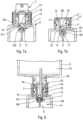
- FIGS. 7a, 7b and 8 illustrates a second embodiment of the invention, which differs only in its support 1', which comprises two separate parts, movable relative to each other.
- This support 1' is part, with the ring 2, of a fixed part F'.
- This support 1' comprises a first part which is formed by a peripheral body 11', a plate 12, a skirt 13, a transition section 14' and a connecting sleeve 17'.
- the plate 12 and the skirt 13 are identical to those of the first embodiment.
- the body 11' is pierced with several windows 15', 16', while the transition section 14' is free of them.
- the sleeve 17' extends inside the body 11': the dip tube D is engaged in the sleeve 17'.
- This support 1' comprises a second part 180 which forms a sealed connection end piece 18', a piston 181 and a spring 182.
- the sealed connection end piece 18' is similar or identical to that of the first embodiment. However, it is axially movable in the body 11' against the spring 182 which extends around the sleeve 17' and bears at the bottom of the transition section 14'.
- the piston extends around the sealed connection end piece 18' and comes into sealed or non-sealed contact with the internal wall of the body 11'.
- the sealed connection end piece 18' and the piston 181 can thus slide in the body 11' between a retracted engagement position shown in the Figure 7a and an extended resting position shown on the Figure 7b .
- the piston 181 is located axially below the windows 15, 16 on the Figure 7a and above windows 15, 16 on the Figure 7b . Communication between the reservoir and the outside through the windows 15, 16 is cut off in the extended rest position. Thus, the risk of spilling fluid contained in the reservoir is very greatly reduced, since it now only communicates through the dip tube D.
- the part 180 therefore fulfills a shutter role when the head T is removed.
- the spring 182 urges the sealed connection end piece 18' against the inlet P2 of the dispensing member P, which improves the seal between them.
- the sliding of the sealed connection end piece 18' can also be used to mount dispensing members P of different sizes or heights.
- a filling source S has been mounted on the first subassembly in place of the head T.
- This source S comprises a source reservoir S1, a mounting ring S2 and a nozzle S3.
- the mounting ring S2 can be screwed onto the fixing ring 2 in place of the capsule 3.
- the S3 nozzle has moved the 18' sealed connection tip into the retracted engagement position, as in the Figure 7a .
- the windows 15', 16' are open and the fluid product from the source tank S2 can flow by gravity into the tank R through one of the windows 15' or 16'.
- the nozzle S3 comprises a short fluid product conduit S4 and a long air conduit S5, which extends into the source tank S2 by a chimney S6.
- the descending fluid product will take the short conduit S4, while the ascending air will take the long conduit S5.
- a one-piece support the body and/or the transition section of which is elastically deformable by elongation.
- the body could, for example, have the shape of a bellows with or without windows. In the rest position, the bellows could at least partially obstruct the windows.
- the transition section would be connected to the internal wall of the neck of the reservoir, while the threads or cam tracks would be directly formed by the external wall of the neck.
- the reservoir would then have to include an attached bottom.
- the screwing/unscrewing connection can be replaced by any other removable connection, for example by magnets, snap-fastening, etc.
Landscapes
- Containers And Packaging Bodies Having A Special Means To Remove Contents (AREA)
- Closures For Containers (AREA)
- Devices For Dispensing Beverages (AREA)
Claims (14)
- Nachfüllbarer Spender für ein Fluidprodukt, umfassend:- ein Fluidproduktreservoir (R), das einen Hals (R2) definiert,- ein Abgabeorgan (P), wie etwa eine Pumpe, das am Hals (R2) des Fluidproduktreservoirs (R) angebracht ist, um das Fluidprodukt zu entnehmen, wobei das Abgabeorgan (P) einen Einlass (P2) aufweist,- ein Befestigungsorgan (2, 3) zum Befestigen des Abgabeorgans (P) an dem Hals (R2) des Fluidproduktreservoirs (R),- ein Tauchrohr (D), das mit dem Einlass (P2) des Abgabeorgans (P) verbunden ist und sich in das Fluidproduktreservoir (R) erstreckt,wobei das Tauchrohr (D) mittels einer Halterung (1; 1') fest mit dem Fluidproduktreservoir (R) verbunden ist, welche zumindest ein Einfüllfenster (15; 15') bildet, das direkt mit dem Inneren des Fluidproduktreservoirs (R) in Verbindung steht, wobei das Befestigungsorgan (2, 3) ein Herausziehen des Abgabeorgans (P) zulässt, so dass ein Zugang zur Halterung (1; 1') möglich ist, um das Fluidproduktreservoir (R) durch das zumindest eine Einfüllfenster (15; 15') zu befüllen, wobei die Halterung (1; 1') in einem feststehenden Abschnitt (F; F') integriert ist, der am Fluidproduktreservoir (R) angebracht ist, und das Abgabeorgan (P) mit einem beweglichen Abschnitt (M) fest verbunden ist, der abnehmbar am feststehenden Abschnitt (F; F') angebracht ist,dadurch gekennzeichnet, dass die Halterung (1; 1') einen ringförmigen Auflageteller (12) aufweist, der oberhalb des Halses (R2) verläuft und eine Pumpendichtung (121) trägt.
- Spender nach Anspruch 1, wobei der feststehende Abschnitt (F; F') einen Befestigungsring (2) umfasst, der erste lösbare Befestigungsmittel (22) bildet, die mit zweiten lösbaren Befestigungsmitteln (33) zusammenwirken, die aus dem beweglichen Abschnitt (M) gebildet sind.
- Spender nach Anspruch 2, wobei der Befestigungsring (2) die Pumpendichtung (121) an der Halterung (1; 1') hält.
- Spender nach Anspruch 2 oder 3, wobei die Halterung (1; 1') eine den Hals (R2) umgreifende Verankerungsschürze (13) bildet, wobei der Befestigungsring (2) die Verankerungsschürze (13) um den Hals (R2) arretiert.
- Spender nach einem der vorangehenden Ansprüche, wobei zwischen dem ringförmigen Auflageteller (12) und dem Hals (R2) eine Halsdichtung (122) angedrückt ist.
- Spender nach einem der vorangehenden Ansprüche, wobei die Pumpendichtung (121) mit einem sich um den Hals (R2) herum erstreckenden Befestigungsring (2) an dem ringförmigen Auflageteller (12) in Position gehalten wird.
- Spender nach Anspruch 6, wobei der Befestigungsring (2) eine eingezogene Lasche (23) aufweist, die mit dem Außenumfang der Pumpendichtung (121) in Eingriff gelangt.
- Spender nach Anspruch 7, wobei der Befestigungsring (2) erste lösbare Befestigungsmittel (22) bildet, die mit zweiten lösbaren Befestigungsmitteln (33) zusammenwirken, die aus dem beweglichen Abschnitt (M) gebildet sind.
- Spender nach einem der vorangehenden Ansprüche, wobei die Halterung (1; 1') zumindest ein Entlüftungsfenster (16; 16') bildet, um Luft aus dem Fluidproduktreservoir (R) entweichen zu lassen, wenn dieser mit Fluidprodukt befüllt wird.
- Spender nach Anspruch 9, wobei das zumindest eine Einfüllfenster (15; 15') und das zumindest eine Entlüftungsfenster (16; 16') auf der gleichen axialen Höhe angeordnet sind.
- Spender nach einem der vorangehenden Ansprüche, wobei die Halterung (1; 1') ein abdichtendes Verbindungsstück (18; 18a; 18') bildet, in das der Einlass (P2) des Abgabeorgans (P) eingreift, wobei das Tauchrohr (D) mit diesem abdichtenden Verbindungsstück (18; 18a; 18') in Fluidverbindung steht.
- Spender nach Anspruch 11, wobei das abdichtende Verbindungsstück (18') zwischen einer ausgefahrenen Ruhestellung und einer eingefahrenen Eingriffsstellung verschiebbar ist, wobei das abdichtende Verbindungsstück (18') in der ausgefahrenen Ruhestellung von Federmitteln (182) beaufschlagt wird, so dass das abdichtende Verbindungsstück (18') in der eingefahrenen Eingriffsstellung federnd gegen den Einlass (P2) des Abgabeorgans (P) gedrückt wird, wobei das Einfüllfenster (15') und/oder das Entlüftungsfenster (16') einen Durchgangsquerschnitt aufweisen, der in der eingefahrenen Eingriffsstellung maximal und in der ausgefahrenen Ruhestellung minimal ist.
- Spender nach Anspruch 12, wobei die Halterung (1') einen Umfangskörper (11') umfasst, in dem das abdichtende Verbindungsstück (18') entgegen der Federmittel (182) gleitet.
- Spender nach Anspruch 9, wobei die Halterung (1; 1') einen Umfangskörper (11; 11'), einen Übergangsabschnitt (14; 14'), ein abdichtendes Verbindungsstück (18; 18a; 18') und einen Anschlussstutzen (17; 17') umfasst, wobei der Umfangskörper (11; 11') und/oder der Übergangsabschnitt (14; 14') das Einfüllfenster (15; 15') und das Entlüftungsfenster (16; 16') bilden, wobei das abdichtende Verbindungsstück (18; 18a; 18') den Einlass (P2) des Abgabeorgans (P) aufnimmt und der Anschlussstutzen (17; 17') das Tauchrohr (D) aufnimmt.
Applications Claiming Priority (2)
| Application Number | Priority Date | Filing Date | Title |
|---|---|---|---|
| FR2007085A FR3112090B1 (fr) | 2020-07-03 | 2020-07-03 | Distributeur de produit fluide |
| PCT/FR2021/051219 WO2022003304A1 (fr) | 2020-07-03 | 2021-07-02 | Distributeur de produit fluide |
Publications (2)
| Publication Number | Publication Date |
|---|---|
| EP4175760A1 EP4175760A1 (de) | 2023-05-10 |
| EP4175760B1 true EP4175760B1 (de) | 2025-04-16 |
Family
ID=73401614
Family Applications (1)
| Application Number | Title | Priority Date | Filing Date |
|---|---|---|---|
| EP21748920.2A Active EP4175760B1 (de) | 2020-07-03 | 2021-07-02 | Fluidspender |
Country Status (7)
| Country | Link |
|---|---|
| US (1) | US12350692B2 (de) |
| EP (1) | EP4175760B1 (de) |
| CN (1) | CN115734825B (de) |
| BR (1) | BR112022027105A2 (de) |
| ES (1) | ES3026753T3 (de) |
| FR (1) | FR3112090B1 (de) |
| WO (1) | WO2022003304A1 (de) |
Families Citing this family (1)
| Publication number | Priority date | Publication date | Assignee | Title |
|---|---|---|---|---|
| FR3167141A1 (fr) | 2024-10-04 | 2026-04-10 | Aptar France Sas | Dispositif de distribution de produit fluide |
Family Cites Families (8)
| Publication number | Priority date | Publication date | Assignee | Title |
|---|---|---|---|---|
| FR2377946A1 (fr) * | 1977-01-19 | 1978-08-18 | Oreal | Recipient de conditionnement et de distribution de liquide comportant une pompe manuelle |
| US5343901A (en) * | 1993-03-17 | 1994-09-06 | Philip Meshberg | Insertable barrier bag or liner for a narrow neck dispensing container and method of filling such a barrier bag or liner |
| US6755327B1 (en) * | 2001-08-29 | 2004-06-29 | Richard H. Davey, Inc. | Dispensing pump with deformable pump wall and positive shut-off |
| EP2409775B1 (de) * | 2009-01-16 | 2015-08-26 | Colgate-Palmolive Company | Abgabebehälter mit Pumpenaufnahmefassung |
| FR2971774B1 (fr) * | 2011-02-23 | 2014-06-06 | Valois Sas | Distributeur de produit fluide |
| WO2014085875A1 (fr) * | 2012-12-06 | 2014-06-12 | Philippe Kriwin | Ensemble rechargeable x |
| FR3004624B1 (fr) * | 2013-04-22 | 2015-05-15 | Aptar France Sas | Distributeur de produit fluide. |
| WO2018172624A1 (fr) * | 2017-03-20 | 2018-09-27 | Aptar France Sas | Distributeur de produit fluide |
-
2020
- 2020-07-03 FR FR2007085A patent/FR3112090B1/fr active Active
-
2021
- 2021-07-02 EP EP21748920.2A patent/EP4175760B1/de active Active
- 2021-07-02 US US18/013,840 patent/US12350692B2/en active Active
- 2021-07-02 WO PCT/FR2021/051219 patent/WO2022003304A1/fr not_active Ceased
- 2021-07-02 ES ES21748920T patent/ES3026753T3/es active Active
- 2021-07-02 BR BR112022027105A patent/BR112022027105A2/pt unknown
- 2021-07-02 CN CN202180046912.0A patent/CN115734825B/zh active Active
Also Published As
| Publication number | Publication date |
|---|---|
| FR3112090A1 (fr) | 2022-01-07 |
| BR112022027105A2 (pt) | 2023-01-31 |
| US20230286001A1 (en) | 2023-09-14 |
| EP4175760A1 (de) | 2023-05-10 |
| WO2022003304A1 (fr) | 2022-01-06 |
| ES3026753T3 (en) | 2025-06-12 |
| US12350692B2 (en) | 2025-07-08 |
| CN115734825A (zh) | 2023-03-03 |
| FR3112090B1 (fr) | 2025-04-11 |
| CN115734825B (zh) | 2026-03-17 |
Similar Documents
| Publication | Publication Date | Title |
|---|---|---|
| EP3999245B1 (de) | Vorrichtung zum verschliessen eines behälters eines flüssigen bis pastösen produkts und mit einer solchen vorrichtung verschlossene nachfüllpackung | |
| WO2007128935A1 (fr) | Organe de distribution de produit fluide et distributeur comprenant un tel organe de distribution | |
| EP2838667B1 (de) | Behälter für ein flüssiges produkt und spender mit einem solchen behälter | |
| FR2997640A1 (fr) | Distributeur de produit fluide | |
| EP3094418B1 (de) | Flüssigkeitsbehälter und spender | |
| EP1472007B1 (de) | Spender für fliessfähige medien mit einer pumpe | |
| EP4175760B1 (de) | Fluidspender | |
| FR2877320A1 (fr) | Organe de distribution de produit fluide et distributeur de produit fluide pourvu d'un tel organe de distribution | |
| EP2934764A1 (de) | Flüssigkeitsspender | |
| FR2643338A1 (fr) | Dispositif distributeur doseur a pompe pour produits fluides | |
| FR2852933A1 (fr) | Distributeur de produit fluide. | |
| EP3525937B1 (de) | Verteiler mit füllkartusche | |
| EP3490406B1 (de) | Vorrichtung zum entnehmen und auftragen eines flüssigprodukts | |
| EP4297910B1 (de) | Reservoir sowie fluidabgabevorrichtung | |
| EP4064927B1 (de) | Vorrichtung zur ausgabe eines flüssigen oder pastösen produkts | |
| FR3139446A1 (fr) | Ensemble de flacon source et distributeur rechargeable | |
| FR3148385A1 (fr) | Dispositif de distribution de produit fluide | |
| FR3138416A1 (fr) | Distributeur d’un produit fluide, recharge associée et réceptacle associé | |
| EP4587196A1 (de) | Quellenflasche und nachfüllbare spenderanordnung | |
| WO2017220910A1 (fr) | Dispositif de prelevement et d'application de produit fluide. | |
| FR3050724A1 (fr) | Distributeur de produit fluide. | |
| FR2975022A1 (fr) | Dispositif doseur pour fluide |
Legal Events
| Date | Code | Title | Description |
|---|---|---|---|
| STAA | Information on the status of an ep patent application or granted ep patent |
Free format text: STATUS: UNKNOWN |
|
| STAA | Information on the status of an ep patent application or granted ep patent |
Free format text: STATUS: THE INTERNATIONAL PUBLICATION HAS BEEN MADE |
|
| PUAI | Public reference made under article 153(3) epc to a published international application that has entered the european phase |
Free format text: ORIGINAL CODE: 0009012 |
|
| STAA | Information on the status of an ep patent application or granted ep patent |
Free format text: STATUS: REQUEST FOR EXAMINATION WAS MADE |
|
| 17P | Request for examination filed |
Effective date: 20230127 |
|
| AK | Designated contracting states |
Kind code of ref document: A1 Designated state(s): AL AT BE BG CH CY CZ DE DK EE ES FI FR GB GR HR HU IE IS IT LI LT LU LV MC MK MT NL NO PL PT RO RS SE SI SK SM TR |
|
| DAV | Request for validation of the european patent (deleted) | ||
| DAX | Request for extension of the european patent (deleted) | ||
| RIN1 | Information on inventor provided before grant (corrected) |
Inventor name: BERANGER, STEPHANE |
|
| P01 | Opt-out of the competence of the unified patent court (upc) registered |
Effective date: 20230913 |
|
| REG | Reference to a national code |
Ref country code: DE Ref legal event code: R079 Free format text: PREVIOUS MAIN CLASS: B05B0011000000 Ref country code: DE Ref legal event code: R079 Ref document number: 602021029265 Country of ref document: DE Free format text: PREVIOUS MAIN CLASS: B05B0011000000 Ipc: B05B0011100000 |
|
| GRAP | Despatch of communication of intention to grant a patent |
Free format text: ORIGINAL CODE: EPIDOSNIGR1 |
|
| STAA | Information on the status of an ep patent application or granted ep patent |
Free format text: STATUS: GRANT OF PATENT IS INTENDED |
|
| RIC1 | Information provided on ipc code assigned before grant |
Ipc: B05B 15/30 20180101ALI20241024BHEP Ipc: B05B 11/10 20230101AFI20241024BHEP |
|
| INTG | Intention to grant announced |
Effective date: 20241114 |
|
| GRAS | Grant fee paid |
Free format text: ORIGINAL CODE: EPIDOSNIGR3 |
|
| GRAA | (expected) grant |
Free format text: ORIGINAL CODE: 0009210 |
|
| STAA | Information on the status of an ep patent application or granted ep patent |
Free format text: STATUS: THE PATENT HAS BEEN GRANTED |
|
| AK | Designated contracting states |
Kind code of ref document: B1 Designated state(s): AL AT BE BG CH CY CZ DE DK EE ES FI FR GB GR HR HU IE IS IT LI LT LU LV MC MK MT NL NO PL PT RO RS SE SI SK SM TR |
|
| REG | Reference to a national code |
Ref country code: GB Ref legal event code: FG4D Free format text: NOT ENGLISH |
|
| REG | Reference to a national code |
Ref country code: CH Ref legal event code: EP Ref country code: DE Ref legal event code: R096 Ref document number: 602021029265 Country of ref document: DE |
|
| REG | Reference to a national code |
Ref country code: IE Ref legal event code: FG4D Free format text: LANGUAGE OF EP DOCUMENT: FRENCH |
|
| REG | Reference to a national code |
Ref country code: ES Ref legal event code: FG2A Ref document number: 3026753 Country of ref document: ES Kind code of ref document: T3 Effective date: 20250612 |
|
| REG | Reference to a national code |
Ref country code: NL Ref legal event code: MP Effective date: 20250416 |
|
| PG25 | Lapsed in a contracting state [announced via postgrant information from national office to epo] |
Ref country code: NL Free format text: LAPSE BECAUSE OF FAILURE TO SUBMIT A TRANSLATION OF THE DESCRIPTION OR TO PAY THE FEE WITHIN THE PRESCRIBED TIME-LIMIT Effective date: 20250416 |
|
| REG | Reference to a national code |
Ref country code: AT Ref legal event code: MK05 Ref document number: 1785234 Country of ref document: AT Kind code of ref document: T Effective date: 20250416 |
|
| PG25 | Lapsed in a contracting state [announced via postgrant information from national office to epo] |
Ref country code: FI Free format text: LAPSE BECAUSE OF FAILURE TO SUBMIT A TRANSLATION OF THE DESCRIPTION OR TO PAY THE FEE WITHIN THE PRESCRIBED TIME-LIMIT Effective date: 20250416 Ref country code: PT Free format text: LAPSE BECAUSE OF FAILURE TO SUBMIT A TRANSLATION OF THE DESCRIPTION OR TO PAY THE FEE WITHIN THE PRESCRIBED TIME-LIMIT Effective date: 20250818 |
|
| PGFP | Annual fee paid to national office [announced via postgrant information from national office to epo] |
Ref country code: ES Payment date: 20250811 Year of fee payment: 5 |
|
| REG | Reference to a national code |
Ref country code: LT Ref legal event code: MG9D |
|
| PG25 | Lapsed in a contracting state [announced via postgrant information from national office to epo] |
Ref country code: GR Free format text: LAPSE BECAUSE OF FAILURE TO SUBMIT A TRANSLATION OF THE DESCRIPTION OR TO PAY THE FEE WITHIN THE PRESCRIBED TIME-LIMIT Effective date: 20250717 Ref country code: NO Free format text: LAPSE BECAUSE OF FAILURE TO SUBMIT A TRANSLATION OF THE DESCRIPTION OR TO PAY THE FEE WITHIN THE PRESCRIBED TIME-LIMIT Effective date: 20250716 |
|
| PG25 | Lapsed in a contracting state [announced via postgrant information from national office to epo] |
Ref country code: PL Free format text: LAPSE BECAUSE OF FAILURE TO SUBMIT A TRANSLATION OF THE DESCRIPTION OR TO PAY THE FEE WITHIN THE PRESCRIBED TIME-LIMIT Effective date: 20250416 |
|
| PG25 | Lapsed in a contracting state [announced via postgrant information from national office to epo] |
Ref country code: BG Free format text: LAPSE BECAUSE OF FAILURE TO SUBMIT A TRANSLATION OF THE DESCRIPTION OR TO PAY THE FEE WITHIN THE PRESCRIBED TIME-LIMIT Effective date: 20250416 |
|
| PG25 | Lapsed in a contracting state [announced via postgrant information from national office to epo] |
Ref country code: HR Free format text: LAPSE BECAUSE OF FAILURE TO SUBMIT A TRANSLATION OF THE DESCRIPTION OR TO PAY THE FEE WITHIN THE PRESCRIBED TIME-LIMIT Effective date: 20250416 |
|
| PG25 | Lapsed in a contracting state [announced via postgrant information from national office to epo] |
Ref country code: AT Free format text: LAPSE BECAUSE OF FAILURE TO SUBMIT A TRANSLATION OF THE DESCRIPTION OR TO PAY THE FEE WITHIN THE PRESCRIBED TIME-LIMIT Effective date: 20250416 |
|
| PGFP | Annual fee paid to national office [announced via postgrant information from national office to epo] |
Ref country code: FR Payment date: 20250730 Year of fee payment: 5 |
|
| PG25 | Lapsed in a contracting state [announced via postgrant information from national office to epo] |
Ref country code: RS Free format text: LAPSE BECAUSE OF FAILURE TO SUBMIT A TRANSLATION OF THE DESCRIPTION OR TO PAY THE FEE WITHIN THE PRESCRIBED TIME-LIMIT Effective date: 20250716 |
|
| PG25 | Lapsed in a contracting state [announced via postgrant information from national office to epo] |
Ref country code: IS Free format text: LAPSE BECAUSE OF FAILURE TO SUBMIT A TRANSLATION OF THE DESCRIPTION OR TO PAY THE FEE WITHIN THE PRESCRIBED TIME-LIMIT Effective date: 20250816 |
|
| PG25 | Lapsed in a contracting state [announced via postgrant information from national office to epo] |
Ref country code: LV Free format text: LAPSE BECAUSE OF FAILURE TO SUBMIT A TRANSLATION OF THE DESCRIPTION OR TO PAY THE FEE WITHIN THE PRESCRIBED TIME-LIMIT Effective date: 20250416 |
|
| PG25 | Lapsed in a contracting state [announced via postgrant information from national office to epo] |
Ref country code: SM Free format text: LAPSE BECAUSE OF FAILURE TO SUBMIT A TRANSLATION OF THE DESCRIPTION OR TO PAY THE FEE WITHIN THE PRESCRIBED TIME-LIMIT Effective date: 20250416 Ref country code: DK Free format text: LAPSE BECAUSE OF FAILURE TO SUBMIT A TRANSLATION OF THE DESCRIPTION OR TO PAY THE FEE WITHIN THE PRESCRIBED TIME-LIMIT Effective date: 20250416 |
|
| REG | Reference to a national code |
Ref country code: DE Ref legal event code: R097 Ref document number: 602021029265 Country of ref document: DE |
|
| PG25 | Lapsed in a contracting state [announced via postgrant information from national office to epo] |
Ref country code: CZ Free format text: LAPSE BECAUSE OF FAILURE TO SUBMIT A TRANSLATION OF THE DESCRIPTION OR TO PAY THE FEE WITHIN THE PRESCRIBED TIME-LIMIT Effective date: 20250416 |
|
| PG25 | Lapsed in a contracting state [announced via postgrant information from national office to epo] |
Ref country code: EE Free format text: LAPSE BECAUSE OF FAILURE TO SUBMIT A TRANSLATION OF THE DESCRIPTION OR TO PAY THE FEE WITHIN THE PRESCRIBED TIME-LIMIT Effective date: 20250416 |
|
| PG25 | Lapsed in a contracting state [announced via postgrant information from national office to epo] |
Ref country code: SK Free format text: LAPSE BECAUSE OF FAILURE TO SUBMIT A TRANSLATION OF THE DESCRIPTION OR TO PAY THE FEE WITHIN THE PRESCRIBED TIME-LIMIT Effective date: 20250416 |
|
| PG25 | Lapsed in a contracting state [announced via postgrant information from national office to epo] |
Ref country code: IT Free format text: LAPSE BECAUSE OF FAILURE TO SUBMIT A TRANSLATION OF THE DESCRIPTION OR TO PAY THE FEE WITHIN THE PRESCRIBED TIME-LIMIT Effective date: 20250416 |
|
| REG | Reference to a national code |
Ref country code: DE Ref legal event code: R119 Ref document number: 602021029265 Country of ref document: DE |
|
| PLBE | No opposition filed within time limit |
Free format text: ORIGINAL CODE: 0009261 |
|
| STAA | Information on the status of an ep patent application or granted ep patent |
Free format text: STATUS: NO OPPOSITION FILED WITHIN TIME LIMIT |
|
| REG | Reference to a national code |
Ref country code: CH Ref legal event code: H13 Free format text: ST27 STATUS EVENT CODE: U-0-0-H10-H13 (AS PROVIDED BY THE NATIONAL OFFICE) Effective date: 20260224 |
|
| REG | Reference to a national code |
Ref country code: CH Ref legal event code: L10 Free format text: ST27 STATUS EVENT CODE: U-0-0-L10-L00 (AS PROVIDED BY THE NATIONAL OFFICE) Effective date: 20260225 |
|
| PG25 | Lapsed in a contracting state [announced via postgrant information from national office to epo] |
Ref country code: RO Free format text: LAPSE BECAUSE OF FAILURE TO SUBMIT A TRANSLATION OF THE DESCRIPTION OR TO PAY THE FEE WITHIN THE PRESCRIBED TIME-LIMIT Effective date: 20250416 |
|
| PG25 | Lapsed in a contracting state [announced via postgrant information from national office to epo] |
Ref country code: LU Free format text: LAPSE BECAUSE OF NON-PAYMENT OF DUE FEES Effective date: 20250702 |
|
| 26N | No opposition filed |
Effective date: 20260119 |
|
| GBPC | Gb: european patent ceased through non-payment of renewal fee |
Effective date: 20250716 |
|
| REG | Reference to a national code |
Ref country code: BE Ref legal event code: MM Effective date: 20250731 |
|
| PG25 | Lapsed in a contracting state [announced via postgrant information from national office to epo] |
Ref country code: GB Free format text: LAPSE BECAUSE OF NON-PAYMENT OF DUE FEES Effective date: 20250716 |
|
| PG25 | Lapsed in a contracting state [announced via postgrant information from national office to epo] |
Ref country code: DE Free format text: LAPSE BECAUSE OF NON-PAYMENT OF DUE FEES Effective date: 20260203 |
|
| PG25 | Lapsed in a contracting state [announced via postgrant information from national office to epo] |
Ref country code: BE Free format text: LAPSE BECAUSE OF NON-PAYMENT OF DUE FEES Effective date: 20250731 |