EP4294573B1 - Hochdruckwalzenpresse mit vibrierenden seitenwänden - Google Patents
Hochdruckwalzenpresse mit vibrierenden seitenwänden Download PDFInfo
- Publication number
- EP4294573B1 EP4294573B1 EP22706309.6A EP22706309A EP4294573B1 EP 4294573 B1 EP4294573 B1 EP 4294573B1 EP 22706309 A EP22706309 A EP 22706309A EP 4294573 B1 EP4294573 B1 EP 4294573B1
- Authority
- EP
- European Patent Office
- Prior art keywords
- roller
- gap
- grinding
- pressure
- vibration
- Prior art date
- Legal status (The legal status is an assumption and is not a legal conclusion. Google has not performed a legal analysis and makes no representation as to the accuracy of the status listed.)
- Active
Links
Images

Classifications
-
- B—PERFORMING OPERATIONS; TRANSPORTING
- B02—CRUSHING, PULVERISING, OR DISINTEGRATING; PREPARATORY TREATMENT OF GRAIN FOR MILLING
- B02C—CRUSHING, PULVERISING, OR DISINTEGRATING IN GENERAL; MILLING GRAIN
- B02C4/00—Crushing or disintegrating by roller mills
- B02C4/02—Crushing or disintegrating by roller mills with two or more rollers
-
- B—PERFORMING OPERATIONS; TRANSPORTING
- B02—CRUSHING, PULVERISING, OR DISINTEGRATING; PREPARATORY TREATMENT OF GRAIN FOR MILLING
- B02C—CRUSHING, PULVERISING, OR DISINTEGRATING IN GENERAL; MILLING GRAIN
- B02C4/00—Crushing or disintegrating by roller mills
- B02C4/28—Details
- B02C4/283—Lateral sealing shields
-
- B—PERFORMING OPERATIONS; TRANSPORTING
- B02—CRUSHING, PULVERISING, OR DISINTEGRATING; PREPARATORY TREATMENT OF GRAIN FOR MILLING
- B02C—CRUSHING, PULVERISING, OR DISINTEGRATING IN GENERAL; MILLING GRAIN
- B02C4/00—Crushing or disintegrating by roller mills
- B02C4/28—Details
- B02C4/32—Adjusting, applying pressure to, or controlling the distance between, milling members
-
- B—PERFORMING OPERATIONS; TRANSPORTING
- B02—CRUSHING, PULVERISING, OR DISINTEGRATING; PREPARATORY TREATMENT OF GRAIN FOR MILLING
- B02C—CRUSHING, PULVERISING, OR DISINTEGRATING IN GENERAL; MILLING GRAIN
- B02C4/00—Crushing or disintegrating by roller mills
- B02C4/28—Details
- B02C4/42—Driving mechanisms; Roller speed control
- B02C4/423—Driving mechanisms; Roller speed control with vibrating or oscillating mechanisms
-
- B—PERFORMING OPERATIONS; TRANSPORTING
- B30—PRESSES
- B30B—PRESSES IN GENERAL
- B30B3/00—Presses characterised by the use of rotary pressing members, e.g. rollers, rings, discs
- B30B3/04—Presses characterised by the use of rotary pressing members, e.g. rollers, rings, discs co-operating with one another, e.g. with co-operating cones
Definitions
- the invention relates to a high-pressure roller press for comminuting brittle grinding material, comprising at least two grinding rollers arranged next to one another and rotating in opposite directions, which form a roller gap between them, wherein a first grinding roller is a fixed roller and a second grinding roller is a loose roller, and a side wall at each of the two ends of the roller gap.
- High-pressure roller presses are often used to crush or compact brittle, granular material such as ores and rocks. These consist of two press rollers arranged next to each other, rotating in opposite directions and usually of the same size, which rotate at the same peripheral speed and form a narrow roller gap between them. The material to be crushed or compacted is pulled through this roller gap, whereby the material to be crushed or compacted is crushed or compacted under the high pressure that prevails in the roller gap.
- the result of this treatment namely crushing or compacting, depends to a large extent on the material properties of the material to be crushed.
- the crushing in the roller gap described here without shearing and without impact was first described by Schönert et al. in the German patent application DE 27 08 053 A1 as high-pressure comminution and since then it has been considered a type of comminution alongside grinding by shearing and crushing.
- High-pressure roller presses for crushing granular material according to Schönert differ fundamentally from other presses that are used for crushing other materials.
- high-pressure roller presses that intended for crushing rock are not comparable with roller presses, for example for crushing grain.
- Grain is ground in grain rollers.
- Grain rollers have a maximum weight of 100 kg.
- the entire apparatus structure of a grain roller differs greatly from high-pressure roller presses.
- Grain rollers also work by shearing.
- High-pressure roller presses also differ significantly from strip rollers for rolling steel.
- Steel strip rollers are characterized by their smooth running due to their use.
- the steel between the strip rollers is either very ductile because the steel to be rolled is hot-formed, or the steel is cold-formable.
- the smooth running of a steel roller is very high due to the nature of the rolling process. It is therefore possible to operate a strip roller with two rollers arranged horizontally one above the other, whereby the roller gap pressure can be generated by the weight of the rollers and also by hydraulic aids.
- the steel to be rolled passes through the roller gap of a strip roller in a horizontal direction, namely perpendicular to the force of gravity which the upper grinding roller presses onto the strip steel.
- strip rollers can reach a roller gap speed of up to 200 km/h.
- Steel belt rollers are comparable to a cake dough roller that rolls over raw pizza dough and spreads the pizza dough in the process, although the forces acting in a steel belt roller are many orders of magnitude greater.
- High-pressure roller presses for crushing ores and rock usually have rollers arranged horizontally next to one another with the material being ground passing through in a vertical direction. The roller gap speeds in high-pressure roller presses for crushing ores and rock reach speeds in the low double-digit km/h range at best.
- Strip rollers for steel therefore operate at a different extreme than high-pressure roller presses.
- Strip rollers run quickly and evenly and deform ductile steel, which deforms under the roller.
- High-pressure roller presses run slowly, and in the roller gap the material to be ground suddenly and spontaneously gives way to the pressure in the roller gap due to brittleness.
- the rollers are arranged horizontally next to one another and form a roller gap through which the material to be ground runs vertically.
- High-pressure roller presses have a roller gap pressure of 50 MPa and more.
- the overall mechanical behavior of the high-pressure roller press is not comparable to the mechanical behavior of strip rollers arranged vertically one above the other, which also show a dampened and even run due to the ductility of the steel to be rolled.
- the ground material in a high-pressure roller press is inhomogeneously permeated with air, the ground material has the opportunity to escape into the air space as it passes through the roller gap and thus avoid the high pressure in the roller gap, which significantly reduces the shredding performance of the high-pressure roller press. Furthermore, this can cause the high-pressure roller press to run unevenly because the rollers perform a rotational oscillation because the drive of the high-pressure roller press rollers is repeatedly braked and then allowed to run freely again. This abrupt load change continues throughout the entire high-pressure roller press and is noticeable as vibration of the entire high-pressure roller press. Under unfavorable conditions, the vibration can continue into the foundation and, under unfavorable circumstances, even damage the foundation.
- feeding devices for grinding material in such a high-pressure roller press which vary the inflow of grinding material in a controlled manner so that a constant cone of material is formed in the Space between the two counter-rotating rollers.
- this type of pressurization of the roller gap is not sufficient to ensure vibration-free operation of the high-pressure roller press rollers and to achieve continuous operation of the entire shredding machine as a high-pressure roller press.
- Uneven grain distribution in the material to be ground and air inclusions in the material cannot always be sufficiently evened out by simply regulating the material cone in the space between the counter-rotating rollers.
- vibration rods such as those known from concrete casting technology as concrete vibrators
- the vibration rods deaerate the ground material by fluidizing it and thus ensure a more even running.
- the vibration rods are not sufficient for the harsh conditions in the high-pressure roller press.
- the vibration rods are worn out too quickly by the ground material or even bent.
- the service life of concrete vibrators or of metal rods that are vibrated with the help of the concrete vibrator is not sufficient to ensure sufficiently long operation without the high-pressure roller press coming to a standstill.
- the German publication EN 10 2011 018 705 A1 taught to regulate the hydraulics that maintain the pressure in the roller gap according to the vibration of the high-pressure roller press. This regulation leads to a smooth and even running of the high-pressure roller press.
- the document DE202012012460U1 discloses a high-pressure roller press having a control device for controlling the roller gap pressure.
- the present invention is dedicated to the pressure distribution along the roller gap from the middle of the roller gap to the two ends of the roller gap. Because the roller gap is open on both sides, a flow movement of the grinding material takes place in the compaction zone, which begins just above the roller gap and extends into the roller gap. This flow movement results in a material flow from the middle of the roller gap to the two ends of the roller gap. Since the grinding material can flow out of the roller gap at the ends of the roller gap, the grinding material follows the pressure gradient in the gap and thus avoids compression.
- the object of the invention is therefore to uniform the pressure distribution along the roll gap.
- each side wall has a vibration device which causes the side wall to vibrate mechanically.
- the side walls of the high-pressure roller press which close the roller gap, are set into mechanical vibration by a vibration device.
- the mechanical vibrations fluidize the ground material and thus facilitate the gap passage, so that the roller gap pressure in the area of the roller gap ends is constantly increased.
- the roller gap pressure is a quotient of the pressure surface, namely the height of the compaction zone above the roller gap, and the product of the height of the actual compaction zone times the length of the roller gap
- the roller gap pressure decreases in the middle of the roller gap and increases at the ends of the roller gap.
- This pressure equalization means that the loose roller does not wobble, i.e.
- the high-pressure roller press works with constant efficiency over a longer period of time.
- the wear pattern of the grinding rollers is also evened out, so that the grinding rollers do not become too tapered due to wear.
- the energy input of the vibration device into the material to be ground is such that the vibration device operates at a frequency between 10 Hz and 150 Hz, preferably at a frequency between 10 Hz and 60 Hz and introduces an energy input of between 0.1 kJ/m 3 and 10 kJ/m 3 , preferably between 0.1 kJ/m 3 and 1.0 kJ/m 3 into the ground material.
- the design required for this can be determined by simple experimental measurement.
- the energy input depends on the exact geometry of the side wall, which, when vibrated, displays a wave pattern that is individual to the geometry in question.
- the wave pattern in turn is responsible for the points at which the energy is introduced into the ground material.
- the simple experiment requires measuring the power consumption and the mass flow, which can be determined by weighing the ground material that has passed through it.
- the vibration device During operation, it has been found that there is an optimum for the energy input. It can therefore be advantageous for the vibration device to have a control device or to be connected to one which regulates the vibration intensity according to the energy absorbed for operation, with increased energy absorption resulting in a reduction in the vibration intensity and reduced energy absorption resulting in an increase in the vibration intensity.
- This control strategy prevents the side wall from interfering too strongly with the grinding behavior and itself becoming damaged in the process.
- the control strategy can also include control based on the energy consumption of the roller drive. It can therefore be provided that the control device controls cumulatively or alternatively based on the energy consumption of a roller drive, whereby an increased energy consumption of the roller drive results in a reduction in the vibration intensity and a reduced energy consumption results in an increase in the vibration intensity.
- This control strategy takes into account the fact that when a fluidization effect develops in the ground material, the average pressure in the roller gap increases and requires a high drive power of the grinding rollers. However, operation with high drive power is not necessarily the most energy-efficient drive.
- the vibration device is additionally the gap width of the roller gap is controlled, whereby an increased gap width results in an increase in the vibration intensity and a reduced gap width results in a reduction in the vibration intensity.
- This control strategy takes into account the observable effect that the roller gap widens when the roller gap is overfilled. Fluidization of the ground material helps to eliminate the short-term overfilling effect.
- Yet another cumulative or alternative control strategy may include additionally controlling the vibration device according to the inclination of the idler roller to rotate about a vertical axis, with increasing rotational vibration frequency of the idler roller increasing the vibration intensity and vice versa.
- This control strategy includes avoiding a wobbling movement of the idler roller by fractions of an angular degree, with the wobbling occurring at a frequency of less than 0.1 Hz.
- This control strategy involves rather slow changes of parameters with a longer response time than is the case with the previous control strategies.
- position sensors can be used on the bearings, which measure the relative distance of the roller axes of both axes at both ends of the rollers and store them over a longer period of time in the range of 1 min to 10 min for a statistical analysis of the wobbling movement.
- vibration device impulsively.
- a manual triggering device can be provided for the vibration device. An operator operates the triggering device when overfilling is detected in the roller gap.
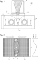
- FIG. 1 a sketch of a high-pressure roller press 100 according to the invention is shown in a side view.
- the high-pressure roller press 100 according to the invention for comminuting brittle grinding material M has at least two grinding rollers 110, 120 arranged next to one another and rotating in opposite directions.
- the two grinding rollers 110, 120 form a roller gap W between them, through which the grinding material M is pulled with no or only very slight relative slip of the grinding rollers 110, 120.
- a first grinding roller (110) is a fixed roller and a second grinding roller 120 is a loose roller.
- the loose roller 120 has two degrees of freedom of movement. It can move away from the fixed roller 110 while widening the roller gap W and can also rotate about the vertical axis A by fractions of an angular degree.
- each side wall 150, 150' has a vibration device which causes the respective side wall 150, 150' to vibrate mechanically. This mechanical vibration is transferred to the ground material M which is located near the respective end of the roller gap W and flows on or in the compaction zone. This vibration fluidizes the ground material M and thereby helps it to pass through the roller gap W, in which a pressure of 50 MPa or higher prevails.
- FIG 2 is a plan view of a roller gap W of a high-pressure roller press 100 covered with grinding material M without side walls 150, 150', shown here in view of the grinding rollers 110, 120.
- the grinding material M is laid as a bulk material on the roller gap W and covers the roller gap W.
- Arrows are drawn on the grinding material M, which show the approximate flow movement of the grinding material M on the Roller gap W up to the area of the compaction zone.
- the actual movement of a grinding material particle is not necessarily the length of the arrows, but can also move only a fraction of it along the paths of the arrows.
- a diagram is shown that shows the possible pressure p in the roll gap W as position x along the roll gap W.
- FIG 3 is a plan view of a roller gap W of a high-pressure roller press 100 covered with grinding material M with static side walls 150, 150', shown here in view of the grinding rollers 110, 120.
- the pressure drop in the roller gap W to the roller shoulder i.e. in the area of one end of the roller gap, is compared to the arrangement in Figure 1 significantly reduced but still present.
- This effect is called the "edge zone effect”.
- This effect is partly caused by the friction on the side wall.
- the side wall forms a flow barrier and the resulting friction increases with increasing pressing pressure because the counter pressure on the side wall surface increases.
- the more the material from the gap is pressed against the side wall the greater the friction coefficient and thus less material flows into the edge zone of the gap. This reduces the material bed compression and thus the resulting pressure of the edge zone accordingly. This leads to a somewhat bell-shaped pressure distribution along the roller gap.
- FIG 4 is a plan view of a roller gap W covered with grinding material M of a high-pressure roller press 100 according to the invention with vibrating side walls 150, 150', here in view of the grinding rollers 110, 120.
- the vibration is generated by a vibration device 160, the intensity of which if necessary, is regulated by a control device 170. Due to the vibrating side wall (150, 150') the pressure at the ends of the roller gap W is maintained because the grinding material M can flow unhindered into the roller gap W. The vibration helps the grinding material M to pass through the roller gap.
- the unhindered flow of material along the entire roller width ensures a uniform pressure profile and uniform wear of the grinding rollers 110 and 120, so that no severe tapering occurs.
Landscapes
- Engineering & Computer Science (AREA)
- Food Science & Technology (AREA)
- Mechanical Engineering (AREA)
- Crushing And Grinding (AREA)
Priority Applications (2)
| Application Number | Priority Date | Filing Date | Title |
|---|---|---|---|
| HRP20241725TT HRP20241725T1 (hr) | 2021-02-18 | 2022-02-17 | Visokotlačni valjkasti mlin s vibrirajućim bočnim stijenkama |
| RS20241414A RS66324B1 (sr) | 2021-02-18 | 2022-02-17 | Visokopritisna presa sa valjcima sa vibrirajućim bočnim zidovima |
Applications Claiming Priority (2)
| Application Number | Priority Date | Filing Date | Title |
|---|---|---|---|
| DE102021103889.8A DE102021103889B4 (de) | 2021-02-18 | 2021-02-18 | Hochdruckwalzenpresse mit vibrierenden Seitenwänden |
| PCT/EP2022/053909 WO2022175372A1 (de) | 2021-02-18 | 2022-02-17 | Hochdruckwalzenpresse mit vibrierenden seitenwänden |
Publications (2)
| Publication Number | Publication Date |
|---|---|
| EP4294573A1 EP4294573A1 (de) | 2023-12-27 |
| EP4294573B1 true EP4294573B1 (de) | 2024-09-18 |
Family
ID=80461024
Family Applications (1)
| Application Number | Title | Priority Date | Filing Date |
|---|---|---|---|
| EP22706309.6A Active EP4294573B1 (de) | 2021-02-18 | 2022-02-17 | Hochdruckwalzenpresse mit vibrierenden seitenwänden |
Country Status (13)
| Country | Link |
|---|---|
| US (1) | US20240226908A9 (pl) |
| EP (1) | EP4294573B1 (pl) |
| KR (1) | KR20230145588A (pl) |
| CN (1) | CN116887922A (pl) |
| DE (1) | DE102021103889B4 (pl) |
| DK (1) | DK4294573T3 (pl) |
| ES (1) | ES3007007T3 (pl) |
| FI (1) | FI4294573T3 (pl) |
| HR (1) | HRP20241725T1 (pl) |
| HU (1) | HUE069659T2 (pl) |
| PL (1) | PL4294573T3 (pl) |
| RS (1) | RS66324B1 (pl) |
| WO (1) | WO2022175372A1 (pl) |
Families Citing this family (1)
| Publication number | Priority date | Publication date | Assignee | Title |
|---|---|---|---|---|
| DE102022121387A1 (de) * | 2022-08-24 | 2024-02-29 | Khd Humboldt Wedag Gmbh | Hochdruckwalzenpresse mit Seitenwandanordnung |
Family Cites Families (10)
| Publication number | Priority date | Publication date | Assignee | Title |
|---|---|---|---|---|
| US2808215A (en) * | 1955-03-03 | 1957-10-01 | Buehler Ag Geb | Sealing shields for roller mills |
| DE2708053C3 (de) | 1977-02-24 | 1986-05-07 | Schönert, Klaus, Prof. Dr.-Ing., 7500 Karlsruhe | Verfahren zur Fein- und Feinstzerkleinerung von Materialien spröden Stoffverhaltens |
| WO2009083005A1 (de) * | 2008-01-03 | 2009-07-09 | Karl-Otto Gericke | Walzenbrecher |
| DE202009014079U1 (de) | 2009-10-17 | 2009-12-31 | Khd Humboldt Wedag Gmbh | Rollenpresse mit Vorrichtung zum Vorverdichten des Mahlgutes |
| DE102011018705C5 (de) * | 2011-04-26 | 2020-03-26 | Khd Humboldt Wedag Gmbh | Verfahren zur Regelung des Walzenspaltdrucks einer Rollenpresse und Rollenpresse |
| DE202012012460U1 (de) * | 2012-01-25 | 2013-01-25 | Thyssenkrupp Polysius Ag | Walzenpresse zur Zerkleinerung von sprödem Mahlgut |
| DE102014100199B3 (de) * | 2014-01-09 | 2015-02-19 | Thyssenkrupp Ag | Verfahren zum Betreiben einer Walzenmühle sowie eine Walzenmühle zur Zerkleinerung von sprödem Mahlgut |
| CN205731381U (zh) * | 2016-05-16 | 2016-11-30 | 兰州交通大学 | 一种辊压机 |
| DE102019120469B4 (de) * | 2019-07-30 | 2025-07-24 | Khd Humboldt Wedag Gmbh | Aufgabevorrichtung für eine Hochdruckwalzenpresse |
| CN111266292A (zh) * | 2020-03-20 | 2020-06-12 | 辽宁科技大学 | 一种电磁复合振动式物料分层装置及其使用方法 |
-
2021
- 2021-02-18 DE DE102021103889.8A patent/DE102021103889B4/de active Active
-
2022
- 2022-02-17 CN CN202280015817.9A patent/CN116887922A/zh active Pending
- 2022-02-17 ES ES22706309T patent/ES3007007T3/es active Active
- 2022-02-17 KR KR1020237031281A patent/KR20230145588A/ko active Pending
- 2022-02-17 PL PL22706309.6T patent/PL4294573T3/pl unknown
- 2022-02-17 HU HUE22706309A patent/HUE069659T2/hu unknown
- 2022-02-17 WO PCT/EP2022/053909 patent/WO2022175372A1/de not_active Ceased
- 2022-02-17 EP EP22706309.6A patent/EP4294573B1/de active Active
- 2022-02-17 FI FIEP22706309.6T patent/FI4294573T3/fi active
- 2022-02-17 HR HRP20241725TT patent/HRP20241725T1/hr unknown
- 2022-02-17 RS RS20241414A patent/RS66324B1/sr unknown
- 2022-02-17 DK DK22706309.6T patent/DK4294573T3/da active
- 2022-02-17 US US18/546,724 patent/US20240226908A9/en active Pending
Also Published As
| Publication number | Publication date |
|---|---|
| RS66324B1 (sr) | 2025-01-31 |
| CN116887922A (zh) | 2023-10-13 |
| PL4294573T4 (pl) | 2025-03-03 |
| EP4294573A1 (de) | 2023-12-27 |
| DE102021103889B4 (de) | 2024-03-07 |
| HUE069659T2 (hu) | 2025-04-28 |
| PL4294573T3 (pl) | 2025-03-03 |
| US20240226908A9 (en) | 2024-07-11 |
| DE102021103889A1 (de) | 2022-08-18 |
| HRP20241725T1 (hr) | 2025-02-28 |
| US20240131524A1 (en) | 2024-04-25 |
| KR20230145588A (ko) | 2023-10-17 |
| ES3007007T3 (en) | 2025-03-19 |
| FI4294573T3 (fi) | 2024-12-19 |
| DK4294573T3 (da) | 2025-01-02 |
| WO2022175372A1 (de) | 2022-08-25 |
Similar Documents
| Publication | Publication Date | Title |
|---|---|---|
| DE102011018705B4 (de) | Verfahren zur Regelung des Walzenspaltdrucks einer Rollenpresse und Rollenpresse | |
| EP2525911B1 (de) | Verfahren und vorrichtung zur vor- und fertigmahlung von mineralischen und nichtmineralischen materialien | |
| DE3855619T2 (de) | Walzenbrecher und Brechverfahren mit Anwendung desselben | |
| EP2307144B1 (de) | Aufgabevorrichtung mit zwei unabhängig voneinander variierbaren drehschiebern | |
| EP4294572B1 (de) | Hochdruck-walzenpresse | |
| EP4294573B1 (de) | Hochdruckwalzenpresse mit vibrierenden seitenwänden | |
| DE4226182A1 (de) | Anlage und Verfahren zur Druckbehandlung körnigen Gutes | |
| DE102020115891B3 (de) | Hochdruckwalzenpresse mit Vibrationsvorrichtung in der Aufgabevorrichtung | |
| EP4106924A1 (de) | Hochdruck-walzenpresse | |
| DE102020110468B4 (de) | Verfahren zur Regelung der Dämpfung der Bewegung einer Presswalze einer Hochdruckwalzenpresse und korrespondierende Hochdruckwalzenpresse | |
| EP2560761B2 (de) | Aufgabevorrichtung für eine hochdruckrollenpresse | |
| EP2488304B1 (de) | Rollenpresse mit vorrichtung zum vorverdichten des mahlgutes | |
| DE202010009151U1 (de) | Aufgabeschacht für eine Walzenpresse | |
| EP0636414A2 (de) | Kollergang | |
| DE102019210047B3 (de) | Vertikal-Rollenmühle | |
| DE202019100300U1 (de) | Hochdruckrollenpresse mit konischen Mahlwalzen | |
| EP3294539A1 (de) | Kontinuierlich arbeitende presse |
Legal Events
| Date | Code | Title | Description |
|---|---|---|---|
| REG | Reference to a national code |
Ref country code: HR Ref legal event code: TUEP Ref document number: P20241725T Country of ref document: HR |
|
| STAA | Information on the status of an ep patent application or granted ep patent |
Free format text: STATUS: UNKNOWN |
|
| STAA | Information on the status of an ep patent application or granted ep patent |
Free format text: STATUS: THE INTERNATIONAL PUBLICATION HAS BEEN MADE |
|
| PUAI | Public reference made under article 153(3) epc to a published international application that has entered the european phase |
Free format text: ORIGINAL CODE: 0009012 |
|
| STAA | Information on the status of an ep patent application or granted ep patent |
Free format text: STATUS: REQUEST FOR EXAMINATION WAS MADE |
|
| 17P | Request for examination filed |
Effective date: 20230913 |
|
| AK | Designated contracting states |
Kind code of ref document: A1 Designated state(s): AL AT BE BG CH CY CZ DE DK EE ES FI FR GB GR HR HU IE IS IT LI LT LU LV MC MK MT NL NO PL PT RO RS SE SI SK SM TR |
|
| GRAP | Despatch of communication of intention to grant a patent |
Free format text: ORIGINAL CODE: EPIDOSNIGR1 |
|
| STAA | Information on the status of an ep patent application or granted ep patent |
Free format text: STATUS: GRANT OF PATENT IS INTENDED |
|
| INTG | Intention to grant announced |
Effective date: 20240409 |
|
| DAV | Request for validation of the european patent (deleted) | ||
| DAX | Request for extension of the european patent (deleted) | ||
| GRAS | Grant fee paid |
Free format text: ORIGINAL CODE: EPIDOSNIGR3 |
|
| GRAA | (expected) grant |
Free format text: ORIGINAL CODE: 0009210 |
|
| STAA | Information on the status of an ep patent application or granted ep patent |
Free format text: STATUS: THE PATENT HAS BEEN GRANTED |
|
| AK | Designated contracting states |
Kind code of ref document: B1 Designated state(s): AL AT BE BG CH CY CZ DE DK EE ES FI FR GB GR HR HU IE IS IT LI LT LU LV MC MK MT NL NO PL PT RO RS SE SI SK SM TR |
|
| REG | Reference to a national code |
Ref country code: GB Ref legal event code: FG4D Free format text: NOT ENGLISH |
|
| REG | Reference to a national code |
Ref country code: CH Ref legal event code: EP |
|
| REG | Reference to a national code |
Ref country code: IE Ref legal event code: FG4D Free format text: LANGUAGE OF EP DOCUMENT: GERMAN |
|
| REG | Reference to a national code |
Ref country code: DE Ref legal event code: R096 Ref document number: 502022001710 Country of ref document: DE |
|
| REG | Reference to a national code |
Ref country code: FI Ref legal event code: FGE |
|
| REG | Reference to a national code |
Ref country code: DK Ref legal event code: T3 Effective date: 20241219 |
|
| REG | Reference to a national code |
Ref country code: NL Ref legal event code: FP |
|
| REG | Reference to a national code |
Ref country code: LT Ref legal event code: MG9D |
|
| PG25 | Lapsed in a contracting state [announced via postgrant information from national office to epo] |
Ref country code: NO Free format text: LAPSE BECAUSE OF FAILURE TO SUBMIT A TRANSLATION OF THE DESCRIPTION OR TO PAY THE FEE WITHIN THE PRESCRIBED TIME-LIMIT Effective date: 20241218 |
|
| PG25 | Lapsed in a contracting state [announced via postgrant information from national office to epo] |
Ref country code: GR Free format text: LAPSE BECAUSE OF FAILURE TO SUBMIT A TRANSLATION OF THE DESCRIPTION OR TO PAY THE FEE WITHIN THE PRESCRIBED TIME-LIMIT Effective date: 20241219 |
|
| PG25 | Lapsed in a contracting state [announced via postgrant information from national office to epo] |
Ref country code: BG Free format text: LAPSE BECAUSE OF FAILURE TO SUBMIT A TRANSLATION OF THE DESCRIPTION OR TO PAY THE FEE WITHIN THE PRESCRIBED TIME-LIMIT Effective date: 20240918 |
|
| PG25 | Lapsed in a contracting state [announced via postgrant information from national office to epo] |
Ref country code: LV Free format text: LAPSE BECAUSE OF FAILURE TO SUBMIT A TRANSLATION OF THE DESCRIPTION OR TO PAY THE FEE WITHIN THE PRESCRIBED TIME-LIMIT Effective date: 20240918 |
|
| PG25 | Lapsed in a contracting state [announced via postgrant information from national office to epo] |
Ref country code: NO Free format text: LAPSE BECAUSE OF FAILURE TO SUBMIT A TRANSLATION OF THE DESCRIPTION OR TO PAY THE FEE WITHIN THE PRESCRIBED TIME-LIMIT Effective date: 20241218 Ref country code: LV Free format text: LAPSE BECAUSE OF FAILURE TO SUBMIT A TRANSLATION OF THE DESCRIPTION OR TO PAY THE FEE WITHIN THE PRESCRIBED TIME-LIMIT Effective date: 20240918 Ref country code: GR Free format text: LAPSE BECAUSE OF FAILURE TO SUBMIT A TRANSLATION OF THE DESCRIPTION OR TO PAY THE FEE WITHIN THE PRESCRIBED TIME-LIMIT Effective date: 20241219 Ref country code: BG Free format text: LAPSE BECAUSE OF FAILURE TO SUBMIT A TRANSLATION OF THE DESCRIPTION OR TO PAY THE FEE WITHIN THE PRESCRIBED TIME-LIMIT Effective date: 20240918 |
|
| REG | Reference to a national code |
Ref country code: HR Ref legal event code: T1PR Ref document number: P20241725 Country of ref document: HR |
|
| REG | Reference to a national code |
Ref country code: HR Ref legal event code: ODRP Ref document number: P20241725 Country of ref document: HR Payment date: 20250207 Year of fee payment: 4 |
|
| PGFP | Annual fee paid to national office [announced via postgrant information from national office to epo] |
Ref country code: NL Payment date: 20250218 Year of fee payment: 4 |
|
| REG | Reference to a national code |
Ref country code: ES Ref legal event code: FG2A Ref document number: 3007007 Country of ref document: ES Kind code of ref document: T3 Effective date: 20250319 |
|
| PGFP | Annual fee paid to national office [announced via postgrant information from national office to epo] |
Ref country code: HU Payment date: 20250220 Year of fee payment: 4 |
|
| PG25 | Lapsed in a contracting state [announced via postgrant information from national office to epo] |
Ref country code: PT Free format text: LAPSE BECAUSE OF FAILURE TO SUBMIT A TRANSLATION OF THE DESCRIPTION OR TO PAY THE FEE WITHIN THE PRESCRIBED TIME-LIMIT Effective date: 20250120 Ref country code: IS Free format text: LAPSE BECAUSE OF FAILURE TO SUBMIT A TRANSLATION OF THE DESCRIPTION OR TO PAY THE FEE WITHIN THE PRESCRIBED TIME-LIMIT Effective date: 20250118 |
|
| PGFP | Annual fee paid to national office [announced via postgrant information from national office to epo] |
Ref country code: HR Payment date: 20250207 Year of fee payment: 4 |
|
| PG25 | Lapsed in a contracting state [announced via postgrant information from national office to epo] |
Ref country code: SM Free format text: LAPSE BECAUSE OF FAILURE TO SUBMIT A TRANSLATION OF THE DESCRIPTION OR TO PAY THE FEE WITHIN THE PRESCRIBED TIME-LIMIT Effective date: 20240918 Ref country code: RO Free format text: LAPSE BECAUSE OF FAILURE TO SUBMIT A TRANSLATION OF THE DESCRIPTION OR TO PAY THE FEE WITHIN THE PRESCRIBED TIME-LIMIT Effective date: 20240918 |
|
| PGFP | Annual fee paid to national office [announced via postgrant information from national office to epo] |
Ref country code: DK Payment date: 20250224 Year of fee payment: 4 Ref country code: FI Payment date: 20250220 Year of fee payment: 4 |
|
| PG25 | Lapsed in a contracting state [announced via postgrant information from national office to epo] |
Ref country code: EE Free format text: LAPSE BECAUSE OF FAILURE TO SUBMIT A TRANSLATION OF THE DESCRIPTION OR TO PAY THE FEE WITHIN THE PRESCRIBED TIME-LIMIT Effective date: 20240918 |
|
| PGFP | Annual fee paid to national office [announced via postgrant information from national office to epo] |
Ref country code: CH Payment date: 20250301 Year of fee payment: 4 Ref country code: AT Payment date: 20250417 Year of fee payment: 4 Ref country code: BE Payment date: 20250218 Year of fee payment: 4 |
|
| PGFP | Annual fee paid to national office [announced via postgrant information from national office to epo] |
Ref country code: FR Payment date: 20250227 Year of fee payment: 4 Ref country code: PL Payment date: 20250207 Year of fee payment: 4 Ref country code: CZ Payment date: 20250212 Year of fee payment: 4 |
|
| PG25 | Lapsed in a contracting state [announced via postgrant information from national office to epo] |
Ref country code: SK Free format text: LAPSE BECAUSE OF FAILURE TO SUBMIT A TRANSLATION OF THE DESCRIPTION OR TO PAY THE FEE WITHIN THE PRESCRIBED TIME-LIMIT Effective date: 20240918 |
|
| PGFP | Annual fee paid to national office [announced via postgrant information from national office to epo] |
Ref country code: IT Payment date: 20250228 Year of fee payment: 4 |
|
| REG | Reference to a national code |
Ref country code: HU Ref legal event code: AG4A Ref document number: E069659 Country of ref document: HU |
|
| PGFP | Annual fee paid to national office [announced via postgrant information from national office to epo] |
Ref country code: RS Payment date: 20250207 Year of fee payment: 4 |
|
| PGFP | Annual fee paid to national office [announced via postgrant information from national office to epo] |
Ref country code: TR Payment date: 20250210 Year of fee payment: 4 |
|
| REG | Reference to a national code |
Ref country code: DE Ref legal event code: R097 Ref document number: 502022001710 Country of ref document: DE |
|
| PGFP | Annual fee paid to national office [announced via postgrant information from national office to epo] |
Ref country code: DE Payment date: 20250428 Year of fee payment: 4 |
|
| PGFP | Annual fee paid to national office [announced via postgrant information from national office to epo] |
Ref country code: ES Payment date: 20250331 Year of fee payment: 4 |
|
| PLBE | No opposition filed within time limit |
Free format text: ORIGINAL CODE: 0009261 |
|
| STAA | Information on the status of an ep patent application or granted ep patent |
Free format text: STATUS: NO OPPOSITION FILED WITHIN TIME LIMIT |
|
| 26N | No opposition filed |
Effective date: 20250619 |
|
| PG25 | Lapsed in a contracting state [announced via postgrant information from national office to epo] |
Ref country code: SE Free format text: LAPSE BECAUSE OF FAILURE TO SUBMIT A TRANSLATION OF THE DESCRIPTION OR TO PAY THE FEE WITHIN THE PRESCRIBED TIME-LIMIT Effective date: 20240918 |
|
| PG25 | Lapsed in a contracting state [announced via postgrant information from national office to epo] |
Ref country code: MC Free format text: LAPSE BECAUSE OF FAILURE TO SUBMIT A TRANSLATION OF THE DESCRIPTION OR TO PAY THE FEE WITHIN THE PRESCRIBED TIME-LIMIT Effective date: 20240918 |
|
| PG25 | Lapsed in a contracting state [announced via postgrant information from national office to epo] |
Ref country code: LU Free format text: LAPSE BECAUSE OF NON-PAYMENT OF DUE FEES Effective date: 20250217 |