EP4293282A2 - Wasserheizvorrichtung mit flammensensor - Google Patents
Wasserheizvorrichtung mit flammensensor Download PDFInfo
- Publication number
- EP4293282A2 EP4293282A2 EP23165324.7A EP23165324A EP4293282A2 EP 4293282 A2 EP4293282 A2 EP 4293282A2 EP 23165324 A EP23165324 A EP 23165324A EP 4293282 A2 EP4293282 A2 EP 4293282A2
- Authority
- EP
- European Patent Office
- Prior art keywords
- hole
- detecting sensor
- heating device
- mounting hole
- water heating
- Prior art date
- Legal status (The legal status is an assumption and is not a legal conclusion. Google has not performed a legal analysis and makes no representation as to the accuracy of the status listed.)
- Pending
Links
Images



Classifications
-
- F—MECHANICAL ENGINEERING; LIGHTING; HEATING; WEAPONS; BLASTING
- F23—COMBUSTION APPARATUS; COMBUSTION PROCESSES
- F23D—BURNERS
- F23D14/00—Burners for combustion of a gas, e.g. of a gas stored under pressure as a liquid
- F23D14/02—Premix gas burners, i.e. in which gaseous fuel is mixed with combustion air upstream of the combustion zone
-
- F—MECHANICAL ENGINEERING; LIGHTING; HEATING; WEAPONS; BLASTING
- F24—HEATING; RANGES; VENTILATING
- F24H—FLUID HEATERS, e.g. WATER OR AIR HEATERS, HAVING HEAT-GENERATING MEANS, e.g. HEAT PUMPS, IN GENERAL
- F24H9/00—Details
- F24H9/20—Arrangement or mounting of control or safety devices
- F24H9/2007—Arrangement or mounting of control or safety devices for water heaters
- F24H9/2035—Arrangement or mounting of control or safety devices for water heaters using fluid fuel
-
- F—MECHANICAL ENGINEERING; LIGHTING; HEATING; WEAPONS; BLASTING
- F23—COMBUSTION APPARATUS; COMBUSTION PROCESSES
- F23D—BURNERS
- F23D11/00—Burners using a direct spraying action of liquid droplets or vaporised liquid into the combustion space
- F23D11/001—Spraying nozzle combined with forced draft fan in one unit
-
- F—MECHANICAL ENGINEERING; LIGHTING; HEATING; WEAPONS; BLASTING
- F23—COMBUSTION APPARATUS; COMBUSTION PROCESSES
- F23D—BURNERS
- F23D11/00—Burners using a direct spraying action of liquid droplets or vaporised liquid into the combustion space
- F23D11/36—Details
- F23D11/40—Mixing tubes; Burner heads
- F23D11/404—Flame tubes
-
- F—MECHANICAL ENGINEERING; LIGHTING; HEATING; WEAPONS; BLASTING
- F23—COMBUSTION APPARATUS; COMBUSTION PROCESSES
- F23N—REGULATING OR CONTROLLING COMBUSTION
- F23N5/00—Systems for controlling combustion
- F23N5/02—Systems for controlling combustion using devices responsive to thermal changes or to thermal expansion of a medium
-
- F—MECHANICAL ENGINEERING; LIGHTING; HEATING; WEAPONS; BLASTING
- F23—COMBUSTION APPARATUS; COMBUSTION PROCESSES
- F23N—REGULATING OR CONTROLLING COMBUSTION
- F23N5/00—Systems for controlling combustion
- F23N5/02—Systems for controlling combustion using devices responsive to thermal changes or to thermal expansion of a medium
- F23N5/08—Systems for controlling combustion using devices responsive to thermal changes or to thermal expansion of a medium using light-sensitive elements
- F23N5/082—Systems for controlling combustion using devices responsive to thermal changes or to thermal expansion of a medium using light-sensitive elements using electronic means
-
- F—MECHANICAL ENGINEERING; LIGHTING; HEATING; WEAPONS; BLASTING
- F23—COMBUSTION APPARATUS; COMBUSTION PROCESSES
- F23D—BURNERS
- F23D2208/00—Control devices associated with burners
- F23D2208/10—Sensing devices
-
- F—MECHANICAL ENGINEERING; LIGHTING; HEATING; WEAPONS; BLASTING
- F23—COMBUSTION APPARATUS; COMBUSTION PROCESSES
- F23D—BURNERS
- F23D2900/00—Special features of, or arrangements for burners using fluid fuels or solid fuels suspended in a carrier gas
- F23D2900/11403—Flame surrounding tubes in front of burner nozzle
-
- F—MECHANICAL ENGINEERING; LIGHTING; HEATING; WEAPONS; BLASTING
- F23—COMBUSTION APPARATUS; COMBUSTION PROCESSES
- F23N—REGULATING OR CONTROLLING COMBUSTION
- F23N2229/00—Flame sensors
-
- F—MECHANICAL ENGINEERING; LIGHTING; HEATING; WEAPONS; BLASTING
- F23—COMBUSTION APPARATUS; COMBUSTION PROCESSES
- F23N—REGULATING OR CONTROLLING COMBUSTION
- F23N2231/00—Fail safe
-
- F—MECHANICAL ENGINEERING; LIGHTING; HEATING; WEAPONS; BLASTING
- F23—COMBUSTION APPARATUS; COMBUSTION PROCESSES
- F23N—REGULATING OR CONTROLLING COMBUSTION
- F23N2239/00—Fuels
- F23N2239/04—Gaseous fuels
-
- F—MECHANICAL ENGINEERING; LIGHTING; HEATING; WEAPONS; BLASTING
- F23—COMBUSTION APPARATUS; COMBUSTION PROCESSES
- F23N—REGULATING OR CONTROLLING COMBUSTION
- F23N2239/00—Fuels
- F23N2239/06—Liquid fuels
-
- F—MECHANICAL ENGINEERING; LIGHTING; HEATING; WEAPONS; BLASTING
- F23—COMBUSTION APPARATUS; COMBUSTION PROCESSES
- F23N—REGULATING OR CONTROLLING COMBUSTION
- F23N2241/00—Applications
- F23N2241/02—Space-heating
-
- F—MECHANICAL ENGINEERING; LIGHTING; HEATING; WEAPONS; BLASTING
- F23—COMBUSTION APPARATUS; COMBUSTION PROCESSES
- F23N—REGULATING OR CONTROLLING COMBUSTION
- F23N2241/00—Applications
- F23N2241/04—Heating water
-
- F—MECHANICAL ENGINEERING; LIGHTING; HEATING; WEAPONS; BLASTING
- F23—COMBUSTION APPARATUS; COMBUSTION PROCESSES
- F23N—REGULATING OR CONTROLLING COMBUSTION
- F23N2900/00—Special features of, or arrangements for controlling combustion
- F23N2900/05005—Mounting arrangements for sensing, detecting or measuring devices
-
- F—MECHANICAL ENGINEERING; LIGHTING; HEATING; WEAPONS; BLASTING
- F24—HEATING; RANGES; VENTILATING
- F24H—FLUID HEATERS, e.g. WATER OR AIR HEATERS, HAVING HEAT-GENERATING MEANS, e.g. HEAT PUMPS, IN GENERAL
- F24H9/00—Details
- F24H9/0005—Details for water heaters
- F24H9/001—Guiding means
- F24H9/0026—Guiding means in combustion gas channels
- F24H9/0031—Guiding means in combustion gas channels with means for changing or adapting the path of the flue gas
Definitions
- the present disclosure relates to a water heating device.
- a water heating device such as a boiler, heats water that flows in an interior thereof, and provides heating or hot water based on the heated water.
- a burner that induces a combustion reaction in an interior thereof to heat water that is introduced into the interior of the water heating device is provided, and heat generated in the interior of the water heating device may heat the water through the combustion reaction. Because the combustion reaction occurs in the interior of the water heating device, a flame detecting sensor that may sense the interior to monitor an emergency situation, such as a fire, may be provided.
- the flame detecting sensor when excessive heat or the combustion gas due to the combustion reaction in the interior of the water heating device is delivered to the flame detecting sensor, the flame detecting sensor cannot be properly used, for example, soot may be generated or a board may be damaged.
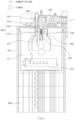
- the burner 300 may include an ignition plug 310.
- the ignition plug 310 may ignite a mixture material, in which the ejected fuel and the ejected air are mixed.
- the ignition plug 310 may generate an electric spark, and a mixture material may be ignited by the electric spark.
- the ignition plug 310 may generate the electric spark in the interior space 110 through an ignition plug hole (e.g., an ignition plug hole 310-1 of FIG. 4 ).
- the burner 300 may include a fuel nozzle 320.
- the fuel nozzle 320 may be a nozzle that may inject the fuel into the interior space 110.
- the fuel nozzle 320 may be disposed to pass through the upper housing 200.
- the burner 300 may include an air nozzle 330.
- the water heating device 1 may include the flame detecting sensor 400.
- the flame detecting sensor 400 may sense physical characteristics, such as a temperature of the flames that may be generated in the interior space 110.
- the flame detecting sensor 400 may be a UV sensor that detects physical characteristics of the flames by receiving ultraviolet rays generated in the interior space 110.
- the flame detecting sensor 400 may detect whether a combustion reaction occurs in the interior space 110, presence of flames, and physical characteristics of the flames.
- the upper housing 200 may include a mounting hole 210.
- the mounting hole 210 may be a hole, into which the flame detecting sensor 400 is inserted to sense the flames in the interior space 110.
- the flame detecting sensor 400 may be disposed to be inserted into the mounting hole 210 to pass through the upper housing 200.
- the upper housing 200 may include a temperature sensor mounting part 201.
- the temperature sensor mounting part 201 may be a hole that is configured such that at least a portion of the temperature sensor that may sense the temperature of the interior space 110 passes through the upper housing 200.
- the temperature sensor may be disposed such that at least a portion thereof is inserted into the temperature sensor mounting part 201 to pass through the upper housing 200.
- the water heating device 1 may include a flame tube 500.
- the flame tube 500 may include a tube part 510 that is formed to surround at least some of the flames that may be generated in the interior space 110.
- the tube part 510 may surround at least a portion of an ignition space that is configured such that the mixture material of the fuel and the air are ignited, and may surround at least some of the flames that are generated through ignition.
- the ignition space may be a partial space included in the interior space 110, and may be a space that is defined while being surrounded by an inner space of the tube part 510.
- the mounting hole 210 may be a hole that is provided in the upper housing 200 such that the flame detecting sensor 400 is mounted therein, and the flame detecting sensor 400 may be inserted into the mounting hole 210 to sense the interior space 110.
- the flame detecting sensor 400 may sense the interior space 110 through the sensing hole 521.
- the sensing hole 521 (or the extending part 520) may be formed at a location corresponding to the mounting hole 210, in the extending part 520 of the flame tube 500, such that the flame detecting sensor 400 senses the interior space 110.
- the flame tube 500 may include a fuel nozzle mounting part 530.
- the fuel nozzle mounting part 530 may be configured such that the fuel nozzle 320 is mounted thereon.
- a fuel nozzle mounting hole 531 may be formed in the fuel nozzle mounting part 530, and at least a portion of the fuel nozzle 320 may be mounted to pass through the fuel nozzle mounting hole 531.
- the fuel nozzle 320 may be mounted on the fuel nozzle mounting part 530 to inject the fuel for generating the combustion reaction in the interior space 110 (or an ignition space that is a partial space of the interior space 110).
- the fuel nozzle 320 may pass through the fuel nozzle hole 320-1 of the upper housing 200 to be mounted on the fuel nozzle mounting part 530.
- the water heating device 1 may include a tube packing 410.
- the tube packing 410 may be disposed between the mounting hole 210 and the extending part 520.
- the tube packing 410 may be disposed between an inner surface (e.g., a second opening inner-surface 121 that will be described below) of the upper housing 200, which defines the mounting hole 210, and the extending part 520.
- the tube packing 410 may be disposed between the extending part 520 and the flame detecting sensor 400.
- the tube packing 410 may define a flow path from the sensing hole 521 of the combustion gas generated by the combustion reaction to the mounting hole 210.
- the tube packing 410 may be disposed between the inner surface (e.g., the second opening inner-surface 1212 that will be described below) and the extending part 520 (or between the extending part 520 and the flame detecting sensor 400) to define a flow path, in which the combustion gas that flows along the extending part 520 in the interior space 110 (or the ignition space that is a partial space of the interior space 110) of the tube part 510 flows.
- the tube packing 410 may restrain the circulating combustion gas from flowing to the mounting hole 210.
- the flow direction of the combustion gas may be reversed by the combustion guide 120, and thus the combustion gas may flow in a direction that faces the mounting hole 210.
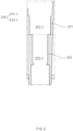
- FIG. 5 illustrates a longitudinal sectional view of the mounting hole 210 according to an embodiment of the present disclosure.
- the contents described in the above-described embodiment may be applied to the present embodiment in the same or similar way.
- the first hole part 211-1 and the second hole part 212-1 may have different cross-sectional areas.
- the first hole part 211-1 may have a first cross-sectional area
- the second hole part 212-1 may have a second cross-sectional area that is smaller than the first cross-sectional area.
- the first hole part 211-1 and the second hole part 212-1 may have different cross-sectional areas with respect to a border that distinguishes them.
- the first cross-sectional area of the first hole part 211-1 corresponding to a border of the first hole part 211-1 and the second hole part 212-1 may be larger than the second cross-sectional area of the second hole part 212-1 corresponding to the border.
- the first opening inner-surface 211 and the second opening inner-surface 212 may define a step.
- the second opening inner-surface 212 may protrude toward the mounting hole 210 such that a step is formed on the first opening inner-surface 211 and the second opening inner-surface 212.
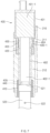
- the flame detecting sensor 400 may include a main part 401.
- the main part 401 may include a main board 401-1.
- the main board 401-1 may be a printed circuit board.
- the flame detecting sensor 400 may include a sub part 402.
- the sub part 402 may be a part that extends from the main part 401 toward the sensing hole 521.
- the sub part 402 may include a sub part end 402-1.
- the sub part end 402-1 may include a lens 435.
- a cross-sectional area of the main part 401 may be larger than a cross-sectional area of the sub part 402.
- the sub part 402 may extend from the main part 401 to include the sub part end 402-1 at an end thereof, and may include a sub board that electrically connects the main board 401-1 and the sub part end 402-1 (or the lens 435) in an interior thereof.
- the sub part 402 including the sub part end 402-1 may extend toward the sensing hole 521 to minimize thermal damage to the main part 401 that senses the flames that may be generated in the interior space 110, due to heat or the combustion gas, or an influence of soot.
- the flame detecting sensor 400 may include a slide preventing pattern 403.
- the slide preventing pattern 403 may be formed on the sub part 402, and the support member 430 described below may be disposed at a location corresponding to the slide preventing pattern 403.
- the water heating device 1, as described above, may include the tube packing 410.
- the tube packing 410 may at least partially surround the extending part 520 and the flame detecting sensor 400.
- the tube packing 410 may be disposed to surround at least a portion of an end of the extending part 520 and at least a portion of an end of the flame detecting sensor 400.
- a diameter of the tube packing 410 may be larger than a diameter of a end of the extending part 520 and a diameter of the flame detecting sensor 400 (or an end of the sub part 402).
- an inner diameter of the tube packing 410 may be larger than an outer diameter of the end of the extending part 520 and an outer diameter of the end of the flame detecting sensor 400.
- the inner diameter of the tube packing 410 may be smaller than or equal to the outer diameter of the end of the extending part 520 and the outer diameter of the end of the flame detecting sensor 400 such that the tube packing 410 is elastically fixed.
- the present disclosure is not limited to the above description, and may be variously implemented according to designs.
- the water heating device 1 may include the sensor packing 420.
- the sensor packing 420 may be disposed between an outer surface of the flame detecting sensor 400 and the opening inner-surfaces 211 and 212.
- the sensor packing 420 may be disposed between the first opening inner-surface 211 that defines the first hole part 211-1 and the sub part 402 of the flame detecting sensor 400.
- the sensor packing 420 may be disposed to surround at least a portion of the sub part 402.
- the sensor packing 420 may be disposed to contact the first opening inner-surface 211, and may be disposed to contact the sub part 402 while contacting the first opening inner-surface 211.
- the sensor packing 420 may include an elastic member.
- the sensor packing 420 may be disposed as described above, and may restrain the combustion gas or the soot from passing through the mounting hole 210. Because the combustion gas or the soot may be restrained from passing through the mounting hole 210, thermal damage to the main board 401-1 of the flame detecting sensor 400 or diffusion of the soot also may be restrained.
- the water heating device 1 may include the support member 430.
- the support member 430 may be disposed between the sensor packing 420 and the main part 401.
- the support member 430 may be disposed between the first opening inner-surface 211 that defines the first hole part 211-1 and the sub part 402 of the flame detecting sensor 400.
- the support member 430 may be disposed to support the sensor packing 420 on an opposite side to the interior space 110 with respect to the sensor packing 420.
- the support member 430 may be disposed on an opposite side to a side that faces the extending part 520 with respect to the sensor packing 420.
- the support member 430 may be disposed to at least partially surround the sub part 402.
- the support member 430 may support the sensor packing 420.
- the support member 430 may be configured to restrain movement of the sub part 402.
- the support member 430 may surround the sub part 402, and may be disposed on the slide preventing pattern 403 such that movement thereof is restrained at a surrounded location. Because the support member 430 is disposed on the slide preventing pattern 403, a relative movement of the support member 430 to the sub part 402 may be restrained further when compared with the sensor packing 420.
- the support member 430 may have a groove 430-1 on an inner surface thereof such that movement thereof with respect to the sub part 402 is restrained.
- the support member 430 may include the groove 430-1 formed on the inner surface thereof in a lengthwise direction of the flame detecting sensor 400, and a disposition form thereof is not particularly restricted.
- the groove 430-1 formed on an inner surface of the support member 430 may protrude from the sub part 402 of the flame detecting sensor 400 to an outside, and may be stopped by a protruding part 404 formed along a lengthwise direction thereof. Because the groove 430-1 of the support member 430 is stopped by the protruding part 404 of the sub part 402, the support member 430 may be prevented from being rotated about the sub part 402 whereby the support member 430 may be prevented from deviating from the flame detecting sensor 400 or an inner surface of the support member 430 may be prevented from being worn. Due to the above-described disposition, the support member 430 may prevent the flame detecting sensor 400 from being pushed out by elasticity of the sensor packing 420, or prevent the sensor packing 420 from being pushed out, or prevent damage to the sensor packing 420.
- the water heating device 1 may include a soot preventing glass 440.
- the soot preventing glass 440 may be provided at the sub part end 402-1.
- the glass 440 may be disposed between the lens 435 provided at the sub part end 402-1 and the sensing hole 521.
- the glass 440 may have a size, by which the sub part end 402-1 (or the lens 435) is covered, and may be disposed to a side that is close to the sensing hole 521 of the sub part end 402-1.
- the glass 440 may have a size of an outer diameter corresponding to an inner diameter of the sub part end 402-1.
- the outer diameter of the glass 440 may be formed to be larger than an outer diameter of the lens 435, but the present disclosure is not limited thereto.
- the glass 440 may be a quartz glass, by which diffusion or adsorption of the soot may be restrained, and may be a complex glass including the quartz glass. Because the glass 440 is disposed around the sub part end 402-1 (or the lens 435), diffusion or adsorption of the soot may be restrained whereby it may be more advantageous for the flame detecting sensor 400 to sense the flames.
- thermal damage to the flame detecting sensor or generation of soot due to the combustion gas may be restrained.
- a durability of the flame detecting sensor may be enhanced.
- an emergency situation may be effectively monitored by restraining damage to the flame detecting sensor.
Landscapes
- Engineering & Computer Science (AREA)
- Chemical & Material Sciences (AREA)
- Combustion & Propulsion (AREA)
- Mechanical Engineering (AREA)
- General Engineering & Computer Science (AREA)
- Physics & Mathematics (AREA)
- Thermal Sciences (AREA)
- Control Of Combustion (AREA)
Applications Claiming Priority (1)
| Application Number | Priority Date | Filing Date | Title |
|---|---|---|---|
| KR1020220071768A KR20230171326A (ko) | 2022-06-13 | 2022-06-13 | 물 가열기 |
Publications (2)
| Publication Number | Publication Date |
|---|---|
| EP4293282A2 true EP4293282A2 (de) | 2023-12-20 |
| EP4293282A3 EP4293282A3 (de) | 2024-02-21 |
Family
ID=85791927
Family Applications (1)
| Application Number | Title | Priority Date | Filing Date |
|---|---|---|---|
| EP23165324.7A Pending EP4293282A3 (de) | 2022-06-13 | 2023-03-30 | Wasserheizvorrichtung mit flammensensor |
Country Status (2)
| Country | Link |
|---|---|
| EP (1) | EP4293282A3 (de) |
| KR (1) | KR20230171326A (de) |
Family Cites Families (5)
| Publication number | Priority date | Publication date | Assignee | Title |
|---|---|---|---|---|
| KR102475418B1 (ko) * | 2019-05-03 | 2022-12-09 | 주식회사 경동나비엔 | 오일 보일러 |
| KR102449885B1 (ko) * | 2019-05-03 | 2022-10-04 | 주식회사 경동나비엔 | 오일 보일러 |
| KR102372925B1 (ko) * | 2019-05-03 | 2022-03-11 | 주식회사 경동나비엔 | 오일 보일러 |
| KR102483154B1 (ko) * | 2019-05-03 | 2023-01-04 | 주식회사 경동나비엔 | 화염튜브 및 이를 이용하는 오일 보일러 |
| KR102435060B1 (ko) * | 2019-05-03 | 2022-08-23 | 주식회사 경동나비엔 | 오일 보일러 |
-
2022
- 2022-06-13 KR KR1020220071768A patent/KR20230171326A/ko active Pending
-
2023
- 2023-03-30 EP EP23165324.7A patent/EP4293282A3/de active Pending
Also Published As
| Publication number | Publication date |
|---|---|
| KR20230171326A (ko) | 2023-12-20 |
| EP4293282A3 (de) | 2024-02-21 |
Similar Documents
| Publication | Publication Date | Title |
|---|---|---|
| JP2010169086A (ja) | ボアクール冷却孔を備えた点火プラグ付きガスエンジン | |
| US6204442B1 (en) | Thermophotovoltaic generator | |
| KR101547716B1 (ko) | 버너 | |
| EP4293282A2 (de) | Wasserheizvorrichtung mit flammensensor | |
| US6702458B2 (en) | Device for installing a thermocouple | |
| RU2738987C1 (ru) | Топочная камера и отопительный котел, содержащий такую камеру | |
| KR20110092293A (ko) | 연소기 | |
| US20070190470A1 (en) | Method for igniting a burner | |
| KR200196669Y1 (ko) | 숯불고기구이기의 가스버너 점화장치 | |
| KR100515605B1 (ko) | 주연료 공급관과 파일럿 버너가 일체화된 축열식 복사관버너 | |
| JP4616717B2 (ja) | 液体燃料燃焼装置 | |
| JP3625175B2 (ja) | 燃焼装置 | |
| JP6430339B2 (ja) | フレームレス燃焼装置 | |
| KR200155549Y1 (ko) | 가스렌지의 세라믹 그릴버너 | |
| CN220287437U (zh) | 火盖及燃气灶 | |
| JP2541740Y2 (ja) | 水素燃焼式水蒸気発生装置 | |
| KR200150047Y1 (ko) | 보일러용 버어너의 연소화염감지 장치 | |
| KR100556394B1 (ko) | 가스복사버너 | |
| KR200158419Y1 (ko) | 가스오븐렌지용 세라믹 그릴버너의 점화장치 | |
| KR100651605B1 (ko) | 연소공기를 이중으로 공급하는 버너 | |
| KR200284931Y1 (ko) | 보일러의 버너구 열교환기능을 갖춘 안전구조 | |
| KR200309360Y1 (ko) | 가스버너의 센서 보호 구조 | |
| KR19980013705U (ko) | 소화방지용 버너 | |
| JP2670957B2 (ja) | 熱板加熱式ガスバーナを用いたガス燃焼装置 | |
| JP7111584B2 (ja) | 加熱調理器 |
Legal Events
| Date | Code | Title | Description |
|---|---|---|---|
| PUAI | Public reference made under article 153(3) epc to a published international application that has entered the european phase |
Free format text: ORIGINAL CODE: 0009012 |
|
| STAA | Information on the status of an ep patent application or granted ep patent |
Free format text: STATUS: THE APPLICATION HAS BEEN PUBLISHED |
|
| AK | Designated contracting states |
Kind code of ref document: A2 Designated state(s): AL AT BE BG CH CY CZ DE DK EE ES FI FR GB GR HR HU IE IS IT LI LT LU LV MC ME MK MT NL NO PL PT RO RS SE SI SK SM TR |
|
| PUAL | Search report despatched |
Free format text: ORIGINAL CODE: 0009013 |
|
| AK | Designated contracting states |
Kind code of ref document: A3 Designated state(s): AL AT BE BG CH CY CZ DE DK EE ES FI FR GB GR HR HU IE IS IT LI LT LU LV MC ME MK MT NL NO PL PT RO RS SE SI SK SM TR |
|
| RIC1 | Information provided on ipc code assigned before grant |
Ipc: F23N 5/08 20060101ALI20240117BHEP Ipc: F23D 14/02 20060101ALI20240117BHEP Ipc: F23D 11/40 20060101ALI20240117BHEP Ipc: F23D 11/00 20060101AFI20240117BHEP |
|
| STAA | Information on the status of an ep patent application or granted ep patent |
Free format text: STATUS: REQUEST FOR EXAMINATION WAS MADE |
|
| 17P | Request for examination filed |
Effective date: 20240820 |
|
| RBV | Designated contracting states (corrected) |
Designated state(s): AL AT BE BG CH CY CZ DE DK EE ES FI FR GB GR HR HU IE IS IT LI LT LU LV MC ME MK MT NL NO PL PT RO RS SE SI SK SM TR |
|
| STAA | Information on the status of an ep patent application or granted ep patent |
Free format text: STATUS: EXAMINATION IS IN PROGRESS |
|
| 17Q | First examination report despatched |
Effective date: 20250731 |
|
| GRAP | Despatch of communication of intention to grant a patent |
Free format text: ORIGINAL CODE: EPIDOSNIGR1 |
|
| STAA | Information on the status of an ep patent application or granted ep patent |
Free format text: STATUS: GRANT OF PATENT IS INTENDED |
|
| INTG | Intention to grant announced |
Effective date: 20260306 |