EP4290671A2 - Batterievorrichtung - Google Patents
Batterievorrichtung Download PDFInfo
- Publication number
- EP4290671A2 EP4290671A2 EP22202379.8A EP22202379A EP4290671A2 EP 4290671 A2 EP4290671 A2 EP 4290671A2 EP 22202379 A EP22202379 A EP 22202379A EP 4290671 A2 EP4290671 A2 EP 4290671A2
- Authority
- EP
- European Patent Office
- Prior art keywords
- welding
- busbar
- battery apparatus
- notches
- insulating
- Prior art date
- Legal status (The legal status is an assumption and is not a legal conclusion. Google has not performed a legal analysis and makes no representation as to the accuracy of the status listed.)
- Pending
Links
Images




Classifications
-
- H—ELECTRICITY
- H01—ELECTRIC ELEMENTS
- H01M—PROCESSES OR MEANS, e.g. BATTERIES, FOR THE DIRECT CONVERSION OF CHEMICAL ENERGY INTO ELECTRICAL ENERGY
- H01M50/00—Constructional details or processes of manufacture of the non-active parts of electrochemical cells other than fuel cells, e.g. hybrid cells
- H01M50/50—Current conducting connections for cells or batteries
- H01M50/502—Interconnectors for connecting terminals of adjacent batteries; Interconnectors for connecting cells outside a battery casing
- H01M50/514—Methods for interconnecting adjacent batteries or cells
- H01M50/516—Methods for interconnecting adjacent batteries or cells by welding, soldering or brazing
-
- H—ELECTRICITY
- H01—ELECTRIC ELEMENTS
- H01M—PROCESSES OR MEANS, e.g. BATTERIES, FOR THE DIRECT CONVERSION OF CHEMICAL ENERGY INTO ELECTRICAL ENERGY
- H01M50/00—Constructional details or processes of manufacture of the non-active parts of electrochemical cells other than fuel cells, e.g. hybrid cells
- H01M50/50—Current conducting connections for cells or batteries
- H01M50/528—Fixed electrical connections, i.e. not intended for disconnection
-
- H—ELECTRICITY
- H01—ELECTRIC ELEMENTS
- H01M—PROCESSES OR MEANS, e.g. BATTERIES, FOR THE DIRECT CONVERSION OF CHEMICAL ENERGY INTO ELECTRICAL ENERGY
- H01M50/00—Constructional details or processes of manufacture of the non-active parts of electrochemical cells other than fuel cells, e.g. hybrid cells
- H01M50/50—Current conducting connections for cells or batteries
- H01M50/502—Interconnectors for connecting terminals of adjacent batteries; Interconnectors for connecting cells outside a battery casing
- H01M50/503—Interconnectors for connecting terminals of adjacent batteries; Interconnectors for connecting cells outside a battery casing characterised by the shape of the interconnectors
-
- H—ELECTRICITY
- H01—ELECTRIC ELEMENTS
- H01M—PROCESSES OR MEANS, e.g. BATTERIES, FOR THE DIRECT CONVERSION OF CHEMICAL ENERGY INTO ELECTRICAL ENERGY
- H01M50/00—Constructional details or processes of manufacture of the non-active parts of electrochemical cells other than fuel cells, e.g. hybrid cells
- H01M50/50—Current conducting connections for cells or batteries
- H01M50/502—Interconnectors for connecting terminals of adjacent batteries; Interconnectors for connecting cells outside a battery casing
- H01M50/507—Interconnectors for connecting terminals of adjacent batteries; Interconnectors for connecting cells outside a battery casing comprising an arrangement of two or more busbars within a container structure, e.g. busbar modules
-
- H—ELECTRICITY
- H01—ELECTRIC ELEMENTS
- H01M—PROCESSES OR MEANS, e.g. BATTERIES, FOR THE DIRECT CONVERSION OF CHEMICAL ENERGY INTO ELECTRICAL ENERGY
- H01M50/00—Constructional details or processes of manufacture of the non-active parts of electrochemical cells other than fuel cells, e.g. hybrid cells
- H01M50/50—Current conducting connections for cells or batteries
- H01M50/543—Terminals
- H01M50/547—Terminals characterised by the disposition of the terminals on the cells
-
- H—ELECTRICITY
- H01—ELECTRIC ELEMENTS
- H01M—PROCESSES OR MEANS, e.g. BATTERIES, FOR THE DIRECT CONVERSION OF CHEMICAL ENERGY INTO ELECTRICAL ENERGY
- H01M50/00—Constructional details or processes of manufacture of the non-active parts of electrochemical cells other than fuel cells, e.g. hybrid cells
- H01M50/50—Current conducting connections for cells or batteries
- H01M50/543—Terminals
- H01M50/547—Terminals characterised by the disposition of the terminals on the cells
- H01M50/55—Terminals characterised by the disposition of the terminals on the cells on the same side of the cell
-
- H—ELECTRICITY
- H01—ELECTRIC ELEMENTS
- H01M—PROCESSES OR MEANS, e.g. BATTERIES, FOR THE DIRECT CONVERSION OF CHEMICAL ENERGY INTO ELECTRICAL ENERGY
- H01M50/00—Constructional details or processes of manufacture of the non-active parts of electrochemical cells other than fuel cells, e.g. hybrid cells
- H01M50/50—Current conducting connections for cells or batteries
- H01M50/543—Terminals
- H01M50/552—Terminals characterised by their shape
-
- H—ELECTRICITY
- H01—ELECTRIC ELEMENTS
- H01M—PROCESSES OR MEANS, e.g. BATTERIES, FOR THE DIRECT CONVERSION OF CHEMICAL ENERGY INTO ELECTRICAL ENERGY
- H01M50/00—Constructional details or processes of manufacture of the non-active parts of electrochemical cells other than fuel cells, e.g. hybrid cells
- H01M50/50—Current conducting connections for cells or batteries
- H01M50/543—Terminals
- H01M50/552—Terminals characterised by their shape
- H01M50/553—Terminals adapted for prismatic, pouch or rectangular cells
-
- H—ELECTRICITY
- H01—ELECTRIC ELEMENTS
- H01M—PROCESSES OR MEANS, e.g. BATTERIES, FOR THE DIRECT CONVERSION OF CHEMICAL ENERGY INTO ELECTRICAL ENERGY
- H01M50/00—Constructional details or processes of manufacture of the non-active parts of electrochemical cells other than fuel cells, e.g. hybrid cells
- H01M50/50—Current conducting connections for cells or batteries
- H01M50/572—Means for preventing undesired use or discharge
- H01M50/584—Means for preventing undesired use or discharge for preventing incorrect connections inside or outside the batteries
- H01M50/588—Means for preventing undesired use or discharge for preventing incorrect connections inside or outside the batteries outside the batteries, e.g. incorrect connections of terminals or busbars
-
- H—ELECTRICITY
- H01—ELECTRIC ELEMENTS
- H01M—PROCESSES OR MEANS, e.g. BATTERIES, FOR THE DIRECT CONVERSION OF CHEMICAL ENERGY INTO ELECTRICAL ENERGY
- H01M50/00—Constructional details or processes of manufacture of the non-active parts of electrochemical cells other than fuel cells, e.g. hybrid cells
- H01M50/50—Current conducting connections for cells or batteries
- H01M50/572—Means for preventing undesired use or discharge
- H01M50/584—Means for preventing undesired use or discharge for preventing incorrect connections inside or outside the batteries
- H01M50/59—Means for preventing undesired use or discharge for preventing incorrect connections inside or outside the batteries characterised by the protection means
- H01M50/593—Spacers; Insulating plates
-
- Y—GENERAL TAGGING OF NEW TECHNOLOGICAL DEVELOPMENTS; GENERAL TAGGING OF CROSS-SECTIONAL TECHNOLOGIES SPANNING OVER SEVERAL SECTIONS OF THE IPC; TECHNICAL SUBJECTS COVERED BY FORMER USPC CROSS-REFERENCE ART COLLECTIONS [XRACs] AND DIGESTS
- Y02—TECHNOLOGIES OR APPLICATIONS FOR MITIGATION OR ADAPTATION AGAINST CLIMATE CHANGE
- Y02E—REDUCTION OF GREENHOUSE GAS [GHG] EMISSIONS, RELATED TO ENERGY GENERATION, TRANSMISSION OR DISTRIBUTION
- Y02E60/00—Enabling technologies; Technologies with a potential or indirect contribution to GHG emissions mitigation
- Y02E60/10—Energy storage using batteries
Definitions
- the disclosure relates to the technical field of batteries, and in particular, relates to a battery apparatus.
- the position of welding between the battery terminal component and the busbar is not accurately positioned, so false welding may easily occur. Further, welding may even be positioned on the insulating member of the battery terminal component, leading to structural damage of the insulating member and the risk of insulation failure as a result.
- the disclosure provides a battery apparatus including a terminal component and a busbar. At least one of the terminal component and the busbar is provided with a welding identification portion, and the welding identification portion includes two notches opposite to each other.
- connection In particular, a reference to “the” object or “a” and “an” object is intended to denote also one of a possible plurality of such objects.
- the terms “connect”, “fix” should be broadly interpreted, for example, the term “connect” can be “fixedly connect”, “detachably connect”, “integrally connect”, “electrically connect” or “signal connect”.
- the term “connect” also can be “directly connect” or “indirectly connect via a medium”.
- the present embodiment provides a battery apparatus including a terminal component 100 and a busbar 200. At least one of the terminal component 100 and the busbar 200 is provided with a welding identification portion, and the welding identification portion includes two notches 300 opposite to each other.
- the welding identification portion includes two opposite notches 300, and the two notches 300 may define a welding region between the terminal component 100 and the busbar 200. To be specific, the two notches 300 may define the center of the welding region between the terminal component 100 and the busbar 200, so that the positioning accuracy of welding between the terminal component 100 and the busbar 200 is improved.
- the battery apparatus further includes a battery 600, and the terminal component 100 is connected to the battery 600.
- the terminal component 100 includes a terminal 103 and an insulating member.
- the terminal 103 includes a first welding surface 104, at least a portion of the insulating member is located at two ends of the first welding surface 104, and the welding identification portion is disposed on the insulating member.
- the busbar 200 is provided with a relief space to expose the welding identification portion on the insulating member.
- the welding region may be formed by the first welding surface 104 of the terminal 103.
- the contour of the first welding surface 104 is generally rectangular.
- the terminal 103 has two opposite long sides and two opposite short sides, and the length of the long sides is greater than the length of the short sides.
- the two short sides are individually named as a first short side and a second short side.
- One of the long sides is connected to a large surface of the battery 600, and the two short sides are both perpendicular to the large surface of the battery 600, where the large surface of the battery 600 refers to the side surface of the battery with the largest area.
- the insulating member and the terminal 103 are injection-molded.
- the insulating member includes a first insulating portion 101 and a second insulating portion 102.
- the first insulating portion 101 is located on the first short side
- the second insulating portion 102 is located on the second short side
- the first insulating portion 101 and the second insulating portion 102 are opposite to each other.
- the welding identification portion is arranged on the insulating member, and to be specific, the welding identification portion is provided on the first insulating portion 101 and the second insulating portion 102.
- a first relief space 202 is provided on the busbar 200 to expose the welding identification portion on the insulating member.
- flanges are formed on both sides of the busbar 200, and the flanges form welding ends 201 of the busbar 200.
- the number of welding ends 201 is two, and the two welding ends 201 are configured to be connected to the positive and negative electrodes of two adjacent batteries 600.
- the first relief space 202 is a concave portion provided on the flange, and exemplarily, the concave portion is a right-angle notch.
- the form of the relief space is not limited to the above, as long as the welding identification portion on the insulating member is exposed through the relief space.
- the two opposite notches 300 are axisymmetrically arranged.
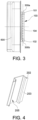
- the two opposite notches 300 are axisymmetrically arranged with respect to the center line (the double-dotted line in FIG. 3 ) of the terminal component 100 perpendicular to the large surface of the battery 600 as the axis of symmetry.
- the notches 300 are of an axisymmetric structure, the axis of symmetry is the center line of the notches 300, and the intersection of the axis of symmetry and the edge of the notches 300 is the midpoint of the notches 300.
- the two opposite notches 300 are located at two ends of the first welding surface 104.
- the two opposite notches 300 are individually named as a first notch 300a and a second notch 300b, the first notch 300a is disposed on the first insulating portion 101, and the second notch 300b is disposed on the second insulating portion 102.
- a connecting line between midpoints of the two opposite notches 300 is a welding reference line.
- the connecting line between the midpoint of the first notch 300a and the midpoint of the second notch 300b is the welding reference line.
- the dotted line represents the welding reference line.
- both the first notch 300a and the second notch 300b are V-shaped notches.
- Each V-shaped notch has a tip, and the tip is the midpoint of the V-shaped notch.
- the tips of the two V-shaped notches are facing each other, and the connecting line between the tips of the two V-shaped notches is the welding reference line. It should be noted that the welding reference line is a virtual straight line.
- the welding equipment may recognize the welding reference line. Further, the welding torch swings on both sides of the reference line, so that the accuracy of welding is ensured.
- the welding reference line overlaps a center line of a welding surface of the terminal component 100.
- the dashed-dotted line represents the center line of the first welding surface 104 of the terminal component 100, and in order to ensure the clarity of the illustration, the dashed line in FIG. 3 is thickened.
- the dotted line overlaps the dashed line.
- the busbar 200 has a second welding surface 203, and a contour of the second welding surface 203 overlaps a contour of the first welding surface 104.
- the busbar 200 has a first surface 204 and a second surface 205 opposite to each other.
- each welding end 201 of the busbar 200 has a surface facing away from the battery and a surface facing the battery.
- the surface of the welding end 201 facing away from the battery is a portion of the first surface 204 of the busbar 200
- the surface of the welding end 201 facing the battery is a portion of the second surface 205 of the busbar 200.
- the second welding surface 203 is the surface of the welding end 201 of the busbar 200 facing the battery. That is, the second welding surface 203 is adhered to the first welding surface 104 and is fixed by welding.
- the contour of the second welding surface 203 substantially overlaps the contour of the first welding surface 104, an in this way, it is ensured that the second welding surface 203 is aligned with the first welding surface 104, and precise welding may thus be easily performed.
- the contour of the second welding surface 203 overlapping the contour of the first welding surface 104 means that the contour of the second welding surface 203 and the contour of the first welding surface 104 substantially overlap.
- the first relief space is formed by the welding identification portion disposed on the busbar 200. That is, both the insulating member of the terminal component 100 and the busbar 200 are provided with welding identification portions.
- the welding identification portion on the busbar 200 overlaps the welding identification portion on the insulating member.
- the welding identification portion on the busbar 200 also includes two V-shaped notches. The two V-shaped notches are opposite to each other and are arranged at both ends of the flanges, and the V-shaped notches on the flanges correspond to the V-shaped notches on the insulating member one by one.
- the welding identification portion on the busbar 200 and the welding identification portion on the insulating member may also partially overlap.
- the projections of the tips of the V-shaped notches on the flanges overlap the tips of the V-shaped notches on the insulating member corresponding to their positions on the first welding surface, or the projections of the tips of the V-shaped notches on the flanges on the first welding surface is located outside the V-shaped notches on the insulating member.
- the included angle between the two side walls of each V-shaped notch on the flange is not less than the included angle between the two side walls of each V-shaped notch on the insulating member.
- the welding identification portion may also be arranged only on the busbar 200.
- the welding identification portion on the busbar 200 also includes two notches 300, and the two notches 300 are opposite to each other and are arranged at both ends of the flange. Both the notches are V-shaped notches.
- the shape of the two notches 300 is not limited to be V-shaped, as long as the connecting line between the two notches 300 may be easily recognized by the welding equipment.
- the shape of the two notches 300 may also be U-shaped, trapezoidal, or rectangular.
- a plurality of busbars 200 are provided, and insulating films 400 are provided on outer surfaces of the plurality of busbars 200.
- Each of the insulating films 400 is provided with a second relief space, and the second relief space corresponds to the welding region to expose the welding region.
- the insulating films 400 on two adjacent busbars 200 are connected through a buffer structure 500.
- an insulating film 400 is provided on the outer surface of each busbar 200, and the insulating films 400 on two adjacent busbars 200 are connected as a whole through the buffer structure 500 to form a wire harness assembly.
- the second relief space may be a relief hole 403, and the relief hole 403 corresponds to the welding ends 201, so that the welding region on the welding ends 201 is exposed, and the welding ends 201 may be easily welded and fixed onto the terminal 103 of the battery.
- each second relief space is not limited to the relief hole 403, but may also be an open second relief space.
- the insulating film 400 includes two sub-film segments, a gap is provided between the two sub-film segments in the length direction of the busbar 200, and the space between the two sub-film segments is the second relief space. As long as it can be ensured that the welding region on the welding ends 201 of the busbar 200 is exposed to the outside of the insulating film 400.
- the buffer structure 500 may improve the buffer strength between the busbars 200, tearing of the insulating films 400 caused by the stress concentration between the busbars 200 may be prevented from occurring as much as possible during assembly or use.
- the insulating films 400 are bonded and fixed to the busbars 200, so that the fixing strength of the busbars 200 may be ensured, and the deviation of the busbars 200 from the welding positions is prevented from occurring.
- the buffer structure 500 and the insulating film 400 are integrally formed.
- the buffer structure 500 is a portion of the insulating film 400. In this way, the overall mechanical strength and buffering performance of the insulating film 400 are improved, the tearing of the insulating film 400 caused by the stress concentration between the busbars 200 is prevented from occurring, and the service life of the wire harness assembly is prolonged.
- the buffer structure 500 and the insulating film 400 are integrally formed, and the busbars 200 may thus be integrated to form a wire harness assembly, which is convenient for assembly.
- each buffer structure 500 includes an elastic member, gaps are provided between at least portions of the buffer structure 500 and the insulating films 400, or the buffer structure 500 is a curved structure located between two adjacent busbars 200.
- the buffer structures 500 includes the elastic members.
- the buffer structures 500 are elastic films.
- Each buffer structure 500 may be connected between two adjacent insulating films 400 or may be connected across the top ends or bottom ends of the two adjacent insulating films 400.
- one buffer structure 500 is connected across the top ends of two adjacent insulating films 400, and one buffer structure 500 is also connected across the bottom ends of the two adjacent insulating films 400.
- a gap is provided between the two adjacent insulating films 400, and the buffer structure 500 is connected to the two adjacent insulating films 400 across the gap, so as to ensure that the buffer structure 500 may be elastically deformed.
- the buffer structure 500 is a curved structure located between two adjacent insulating films 400.
- the two adjacent insulating films 400 are integrally formed with the curved structure, that is, the curved structure is a portion of the insulating films 400. After the busbar 200 is welded and fixed to the terminal 103 of the battery, the curved structure is located between two adjacent busbars 200.
- the connecting line between the two opposite notches 300 is a welding reference line.
- the welding equipment may recognize the abovementioned welding reference line and oscillate on both sides of the welding reference line, and precise welding is thus achieved.
- the curved structure is located between two adjacent busbars 200, so that the stress concentration between the busbars 200 may be relieved or eliminated during subsequent use (e.g., when the battery swells), and the risk of tearing of the insulating films 400 is effectively reduced.
- gaps are provided between at least portions of the buffer structure 500 and the insulating films 400.
- a gap is provided between two adjacent insulating films 400, that is, a gap is provided between two sidewalls of two adjacent insulating films 400 that are close to each other. Gaps being provided between at least portions of the buffer structure 500 and the insulating films 400 ensures that a buffer space is provided between the first film segment and the second film segment.
- Gaps may be provided between at least portions of the buffer structure 500 and the top ends of the insulating films 400 or the sidewalls of the insulating films 400.
- the top and bottom ends of the insulating films 400 refer to the edges of the insulating films 400 parallel to the arrow direction X
- the sidewalls of the insulating films 400 refer to the sides of the insulating films 400 that are perpendicular to the top and bottom ends thereof.
- each the buffer structure 500 includes a first connection segment 501, a second connection segment 502, and a third connection segment 503.
- the first connection segment 501 is connected to one of the insulating films 400
- the second connection segment 502 is connected to another insulating film 400
- the third connection segment 503 is connected between the first connection segment 501 and the second connection segment 502, so that the buffer structure 500 is formed into a zigzag structure.
- the number of buffer structures 500 is two, and the two buffer structures 500 are formed integrally with the insulating films 400.
- One of the buffer structures 500 is connected above two adjacent insulating films 400, and the other buffer structure 500 is connected below two adjacent insulating films 400.
- the first connection segment 501 is integrally formed with the top end of one of the insulating films 400
- the second connection segment 502 is integrally formed with the top end of another insulating film 400
- the third connection segment 503 is connected between the first connection segment 501 and the second connection segment 502, so that the buffer structure 500 is formed into a zigzag structure.
- gaps are provided between the third connection segment 503 and the top ends of two adjacent insulating films 400, and a gap is also provided between the two adjacent insulating films 400.
- first connection segment 501, the second connection segment 502, and the third connection segment 503 are integrally formed.
- first connection segment 501, the second connection segment 502, and the third connection segment 503 are integrally formed with the insulating films 400. In this way, production and processing may be easily performed, and the overall structural strength and buffering performance of the wire harness assembly may be improved.
- the buffer structure 500 may also be an S-shaped structure or a Z-shaped structure.
- the S-shaped structure and the Z-shaped structure may be connected in a gap between two adjacent insulating films 400.
- buffer structure 500 is not limited to the above several forms, and other forms of the buffer structure 500 may also be selected according to actual needs.
- each insulating film 400 includes a first insulating film 401 and a second insulating film 402, the first insulating film is located on the first surface 204 of the busbar 200, and the second insulating film 402 is located on the second surface 205 of the busbar 200.
- the first insulating film 401 is adhered to at least a portion of the first surface 204 of the busbar 200, and the second insulating film 402 is adhered to at least a portion of the second surface 205 of the busbar 200.
- the fixing strength of the insulating film 400 to the busbar 200 may be enhanced, and the problem of inaccurate welding and positioning caused by the loosening of the busbar 200 may be prevented from occurring.
- the second relief space includes a first through hole 4011 arranged on the first insulating film 401 and a second through hole 4021 arranged on the second insulating film 402.
- the first through hole 4011 on the first insulating film 401 may expose at least a portion of the surface of the welding end 201 facing away from the battery
- the second through hole 4021 on the second insulating film 402 may expose at least a portion of the surface of the welding end 201 facing the battery.
- first through hole 4011 and the second through hole 4021 together form the second relief space.
- the number of buffer structures 500 is two, and the two buffer structures 500 are formed integrally with the first insulating film 401.
- first insulating film 401 is connected to the second insulating film 402 through hot pressing.
- the first insulating film 401 and the second insulating film 402 are connected by a hot pressing process, so that the busbar 200 is fixed between the first insulating film 401 and the second insulating film 402.
- the hot pressing process is the related art, and description thereof is not provided in detail herein.
- first insulating film 401 and the second insulating film 402 may also be integrally formed, as long as the busbar 200 may be fixed and the welding end 201 of the busbar 200 may be welded and fixed to the terminal 103 of the battery.
Landscapes
- Chemical & Material Sciences (AREA)
- Chemical Kinetics & Catalysis (AREA)
- Electrochemistry (AREA)
- General Chemical & Material Sciences (AREA)
- Connection Of Batteries Or Terminals (AREA)
- Battery Mounting, Suspending (AREA)
Applications Claiming Priority (1)
| Application Number | Priority Date | Filing Date | Title |
|---|---|---|---|
| CN202210534851.9A CN114914636A (zh) | 2022-05-17 | 2022-05-17 | 电池组 |
Publications (2)
| Publication Number | Publication Date |
|---|---|
| EP4290671A2 true EP4290671A2 (de) | 2023-12-13 |
| EP4290671A3 EP4290671A3 (de) | 2024-06-12 |
Family
ID=82768656
Family Applications (1)
| Application Number | Title | Priority Date | Filing Date |
|---|---|---|---|
| EP22202379.8A Pending EP4290671A3 (de) | 2022-05-17 | 2022-10-19 | Batterievorrichtung |
Country Status (3)
| Country | Link |
|---|---|
| US (1) | US12469933B2 (de) |
| EP (1) | EP4290671A3 (de) |
| CN (1) | CN114914636A (de) |
Families Citing this family (1)
| Publication number | Priority date | Publication date | Assignee | Title |
|---|---|---|---|---|
| CN116053672A (zh) * | 2023-01-13 | 2023-05-02 | 中创新航科技股份有限公司 | 电池及其制造方法、电池装置 |
Family Cites Families (7)
| Publication number | Priority date | Publication date | Assignee | Title |
|---|---|---|---|---|
| US10199626B2 (en) * | 2017-04-28 | 2019-02-05 | Nio Usa, Inc. | Spring loaded busbar for laser welding operation |
| CN206820036U (zh) * | 2017-05-19 | 2017-12-29 | 福州华鹰重工机械有限公司 | 一种电池组的外壳单元、模块单元及电池包 |
| CN110911594B (zh) | 2018-09-14 | 2024-09-06 | 宁德时代新能源科技股份有限公司 | 电池模组及其汇流构件和汇流组件 |
| WO2020235279A1 (ja) | 2019-05-22 | 2020-11-26 | 三洋電機株式会社 | バスバープレート |
| CN210744017U (zh) * | 2019-10-21 | 2020-06-12 | 宁德时代新能源科技股份有限公司 | 线束隔离板组件、电池模块、电池组及装置 |
| CN216413212U (zh) | 2021-12-01 | 2022-04-29 | 宁德时代新能源科技股份有限公司 | 汇流排组件、电池及用电装置 |
| CN217306697U (zh) * | 2022-05-17 | 2022-08-26 | 中创新航科技股份有限公司 | 电池组 |
-
2022
- 2022-05-17 CN CN202210534851.9A patent/CN114914636A/zh active Pending
- 2022-10-18 US US17/967,900 patent/US12469933B2/en active Active
- 2022-10-19 EP EP22202379.8A patent/EP4290671A3/de active Pending
Also Published As
| Publication number | Publication date |
|---|---|
| CN114914636A (zh) | 2022-08-16 |
| US20230378617A1 (en) | 2023-11-23 |
| EP4290671A3 (de) | 2024-06-12 |
| US12469933B2 (en) | 2025-11-11 |
Similar Documents
| Publication | Publication Date | Title |
|---|---|---|
| EP2528143B1 (de) | Stromspeicherelement mit einem stromsammler und verfahren zur herstellung des stromsammlers | |
| KR101818631B1 (ko) | 전지 및 그 제조 방법 | |
| KR101887242B1 (ko) | 축전 소자 및 스페이서 | |
| JP2016129125A (ja) | 蓄電装置 | |
| EP4290671A2 (de) | Batterievorrichtung | |
| CN117766955A (zh) | 二次电池 | |
| CN217306697U (zh) | 电池组 | |
| KR20230012419A (ko) | 단자 부품 및 단자 부품의 제조 방법 | |
| JP4146665B2 (ja) | 密閉型二次電池 | |
| US20250226542A1 (en) | Battery pack | |
| EP4030537B1 (de) | Sekundärbatterie und herstellungsverfahren dafür, batteriemodul und vorrichtung | |
| CN108292732A (zh) | 电池 | |
| EP3598530A1 (de) | Verbindungselement zum anschluss an eine stromschiene einer batterie, batterie | |
| CN217306688U (zh) | 线束组件及电池组 | |
| JPH06215754A (ja) | 電池パック | |
| CN220574982U (zh) | 超声波焊接设备 | |
| JPH09213298A (ja) | 蓄電池および蓄電池用電極板 | |
| US20230019424A1 (en) | Horn, terminal component, and secondary battery | |
| EP4492561A1 (de) | Batterie und verfahren zur herstellung der batterie | |
| JPH11176413A (ja) | 電池の集電体 | |
| JPH11167912A (ja) | 電池パック | |
| JP2003346903A (ja) | 電 池 | |
| JP2018152224A (ja) | 組電池 | |
| CN212810293U (zh) | 用于桥式整流器的跳线结构及整流器 | |
| EP3531478A1 (de) | Stromblockierungsstruktur für pouch-sekundärbatterie |
Legal Events
| Date | Code | Title | Description |
|---|---|---|---|
| PUAI | Public reference made under article 153(3) epc to a published international application that has entered the european phase |
Free format text: ORIGINAL CODE: 0009012 |
|
| STAA | Information on the status of an ep patent application or granted ep patent |
Free format text: STATUS: REQUEST FOR EXAMINATION WAS MADE |
|
| 17P | Request for examination filed |
Effective date: 20221019 |
|
| AK | Designated contracting states |
Kind code of ref document: A2 Designated state(s): AL AT BE BG CH CY CZ DE DK EE ES FI FR GB GR HR HU IE IS IT LI LT LU LV MC ME MK MT NL NO PL PT RO RS SE SI SK SM TR |
|
| PUAL | Search report despatched |
Free format text: ORIGINAL CODE: 0009013 |
|
| AK | Designated contracting states |
Kind code of ref document: A3 Designated state(s): AL AT BE BG CH CY CZ DE DK EE ES FI FR GB GR HR HU IE IS IT LI LT LU LV MC ME MK MT NL NO PL PT RO RS SE SI SK SM TR |
|
| RIC1 | Information provided on ipc code assigned before grant |
Ipc: H01M 50/502 20210101AFI20240506BHEP |