EP4289987A1 - Sintered cbn - Google Patents
Sintered cbn Download PDFInfo
- Publication number
- EP4289987A1 EP4289987A1 EP22749530.6A EP22749530A EP4289987A1 EP 4289987 A1 EP4289987 A1 EP 4289987A1 EP 22749530 A EP22749530 A EP 22749530A EP 4289987 A1 EP4289987 A1 EP 4289987A1
- Authority
- EP
- European Patent Office
- Prior art keywords
- sub
- cbn
- less
- grains
- sintered compact
- Prior art date
- Legal status (The legal status is an assumption and is not a legal conclusion. Google has not performed a legal analysis and makes no representation as to the accuracy of the status listed.)
- Pending
Links
Images

Classifications
-
- C—CHEMISTRY; METALLURGY
- C22—METALLURGY; FERROUS OR NON-FERROUS ALLOYS; TREATMENT OF ALLOYS OR NON-FERROUS METALS
- C22C—ALLOYS
- C22C29/00—Alloys based on carbides, oxides, nitrides, borides, or silicides, e.g. cermets, or other metal compounds, e.g. oxynitrides, sulfides
- C22C29/16—Alloys based on carbides, oxides, nitrides, borides, or silicides, e.g. cermets, or other metal compounds, e.g. oxynitrides, sulfides based on nitrides
-
- C—CHEMISTRY; METALLURGY
- C04—CEMENTS; CONCRETE; ARTIFICIAL STONE; CERAMICS; REFRACTORIES
- C04B—LIME, MAGNESIA; SLAG; CEMENTS; COMPOSITIONS THEREOF, e.g. MORTARS, CONCRETE OR LIKE BUILDING MATERIALS; ARTIFICIAL STONE; CERAMICS; REFRACTORIES; TREATMENT OF NATURAL STONE
- C04B35/00—Shaped ceramic products characterised by their composition; Ceramics compositions; Processing powders of inorganic compounds preparatory to the manufacturing of ceramic products
- C04B35/622—Forming processes; Processing powders of inorganic compounds preparatory to the manufacturing of ceramic products
- C04B35/64—Burning or sintering processes
- C04B35/645—Pressure sintering
-
- C—CHEMISTRY; METALLURGY
- C22—METALLURGY; FERROUS OR NON-FERROUS ALLOYS; TREATMENT OF ALLOYS OR NON-FERROUS METALS
- C22C—ALLOYS
- C22C1/00—Making non-ferrous alloys
- C22C1/04—Making non-ferrous alloys by powder metallurgy
- C22C1/05—Mixtures of metal powder with non-metallic powder
- C22C1/051—Making hard metals based on borides, carbides, nitrides, oxides or silicides; Preparation of the powder mixture used as the starting material therefor
-
- C—CHEMISTRY; METALLURGY
- C22—METALLURGY; FERROUS OR NON-FERROUS ALLOYS; TREATMENT OF ALLOYS OR NON-FERROUS METALS
- C22C—ALLOYS
- C22C29/00—Alloys based on carbides, oxides, nitrides, borides, or silicides, e.g. cermets, or other metal compounds, e.g. oxynitrides, sulfides
- C22C29/005—Alloys based on carbides, oxides, nitrides, borides, or silicides, e.g. cermets, or other metal compounds, e.g. oxynitrides, sulfides comprising a particular metallic binder
-
- B—PERFORMING OPERATIONS; TRANSPORTING
- B22—CASTING; POWDER METALLURGY
- B22F—WORKING METALLIC POWDER; MANUFACTURE OF ARTICLES FROM METALLIC POWDER; MAKING METALLIC POWDER; APPARATUS OR DEVICES SPECIALLY ADAPTED FOR METALLIC POWDER
- B22F5/00—Manufacture of workpieces or articles from metallic powder characterised by the special shape of the product
- B22F2005/001—Cutting tools, earth boring or grinding tool other than table ware
-
- C—CHEMISTRY; METALLURGY
- C04—CEMENTS; CONCRETE; ARTIFICIAL STONE; CERAMICS; REFRACTORIES
- C04B—LIME, MAGNESIA; SLAG; CEMENTS; COMPOSITIONS THEREOF, e.g. MORTARS, CONCRETE OR LIKE BUILDING MATERIALS; ARTIFICIAL STONE; CERAMICS; REFRACTORIES; TREATMENT OF NATURAL STONE
- C04B2235/00—Aspects relating to ceramic starting mixtures or sintered ceramic products
- C04B2235/02—Composition of constituents of the starting material or of secondary phases of the final product
- C04B2235/30—Constituents and secondary phases not being of a fibrous nature
- C04B2235/32—Metal oxides, mixed metal oxides, or oxide-forming salts thereof, e.g. carbonates, nitrates, (oxy)hydroxides, chlorides
- C04B2235/3205—Alkaline earth oxides or oxide forming salts thereof, e.g. beryllium oxide
- C04B2235/3206—Magnesium oxides or oxide-forming salts thereof
-
- C—CHEMISTRY; METALLURGY
- C04—CEMENTS; CONCRETE; ARTIFICIAL STONE; CERAMICS; REFRACTORIES
- C04B—LIME, MAGNESIA; SLAG; CEMENTS; COMPOSITIONS THEREOF, e.g. MORTARS, CONCRETE OR LIKE BUILDING MATERIALS; ARTIFICIAL STONE; CERAMICS; REFRACTORIES; TREATMENT OF NATURAL STONE
- C04B2235/00—Aspects relating to ceramic starting mixtures or sintered ceramic products
- C04B2235/02—Composition of constituents of the starting material or of secondary phases of the final product
- C04B2235/30—Constituents and secondary phases not being of a fibrous nature
- C04B2235/32—Metal oxides, mixed metal oxides, or oxide-forming salts thereof, e.g. carbonates, nitrates, (oxy)hydroxides, chlorides
- C04B2235/3284—Zinc oxides, zincates, cadmium oxides, cadmiates, mercury oxides, mercurates or oxide forming salts thereof
-
- C—CHEMISTRY; METALLURGY
- C04—CEMENTS; CONCRETE; ARTIFICIAL STONE; CERAMICS; REFRACTORIES
- C04B—LIME, MAGNESIA; SLAG; CEMENTS; COMPOSITIONS THEREOF, e.g. MORTARS, CONCRETE OR LIKE BUILDING MATERIALS; ARTIFICIAL STONE; CERAMICS; REFRACTORIES; TREATMENT OF NATURAL STONE
- C04B2235/00—Aspects relating to ceramic starting mixtures or sintered ceramic products
- C04B2235/02—Composition of constituents of the starting material or of secondary phases of the final product
- C04B2235/30—Constituents and secondary phases not being of a fibrous nature
- C04B2235/34—Non-metal oxides, non-metal mixed oxides, or salts thereof that form the non-metal oxides upon heating, e.g. carbonates, nitrates, (oxy)hydroxides, chlorides
- C04B2235/3418—Silicon oxide, silicic acids or oxide forming salts thereof, e.g. silica sol, fused silica, silica fume, cristobalite, quartz or flint
-
- C—CHEMISTRY; METALLURGY
- C04—CEMENTS; CONCRETE; ARTIFICIAL STONE; CERAMICS; REFRACTORIES
- C04B—LIME, MAGNESIA; SLAG; CEMENTS; COMPOSITIONS THEREOF, e.g. MORTARS, CONCRETE OR LIKE BUILDING MATERIALS; ARTIFICIAL STONE; CERAMICS; REFRACTORIES; TREATMENT OF NATURAL STONE
- C04B2235/00—Aspects relating to ceramic starting mixtures or sintered ceramic products
- C04B2235/02—Composition of constituents of the starting material or of secondary phases of the final product
- C04B2235/30—Constituents and secondary phases not being of a fibrous nature
- C04B2235/38—Non-oxide ceramic constituents or additives
- C04B2235/3817—Carbides
-
- C—CHEMISTRY; METALLURGY
- C04—CEMENTS; CONCRETE; ARTIFICIAL STONE; CERAMICS; REFRACTORIES
- C04B—LIME, MAGNESIA; SLAG; CEMENTS; COMPOSITIONS THEREOF, e.g. MORTARS, CONCRETE OR LIKE BUILDING MATERIALS; ARTIFICIAL STONE; CERAMICS; REFRACTORIES; TREATMENT OF NATURAL STONE
- C04B2235/00—Aspects relating to ceramic starting mixtures or sintered ceramic products
- C04B2235/02—Composition of constituents of the starting material or of secondary phases of the final product
- C04B2235/30—Constituents and secondary phases not being of a fibrous nature
- C04B2235/38—Non-oxide ceramic constituents or additives
- C04B2235/3817—Carbides
- C04B2235/3839—Refractory metal carbides
- C04B2235/3843—Titanium carbides
-
- C—CHEMISTRY; METALLURGY
- C04—CEMENTS; CONCRETE; ARTIFICIAL STONE; CERAMICS; REFRACTORIES
- C04B—LIME, MAGNESIA; SLAG; CEMENTS; COMPOSITIONS THEREOF, e.g. MORTARS, CONCRETE OR LIKE BUILDING MATERIALS; ARTIFICIAL STONE; CERAMICS; REFRACTORIES; TREATMENT OF NATURAL STONE
- C04B2235/00—Aspects relating to ceramic starting mixtures or sintered ceramic products
- C04B2235/02—Composition of constituents of the starting material or of secondary phases of the final product
- C04B2235/30—Constituents and secondary phases not being of a fibrous nature
- C04B2235/38—Non-oxide ceramic constituents or additives
- C04B2235/3852—Nitrides, e.g. oxynitrides, carbonitrides, oxycarbonitrides, lithium nitride, magnesium nitride
-
- C—CHEMISTRY; METALLURGY
- C04—CEMENTS; CONCRETE; ARTIFICIAL STONE; CERAMICS; REFRACTORIES
- C04B—LIME, MAGNESIA; SLAG; CEMENTS; COMPOSITIONS THEREOF, e.g. MORTARS, CONCRETE OR LIKE BUILDING MATERIALS; ARTIFICIAL STONE; CERAMICS; REFRACTORIES; TREATMENT OF NATURAL STONE
- C04B2235/00—Aspects relating to ceramic starting mixtures or sintered ceramic products
- C04B2235/02—Composition of constituents of the starting material or of secondary phases of the final product
- C04B2235/30—Constituents and secondary phases not being of a fibrous nature
- C04B2235/38—Non-oxide ceramic constituents or additives
- C04B2235/3852—Nitrides, e.g. oxynitrides, carbonitrides, oxycarbonitrides, lithium nitride, magnesium nitride
- C04B2235/3856—Carbonitrides, e.g. titanium carbonitride, zirconium carbonitride
-
- C—CHEMISTRY; METALLURGY
- C04—CEMENTS; CONCRETE; ARTIFICIAL STONE; CERAMICS; REFRACTORIES
- C04B—LIME, MAGNESIA; SLAG; CEMENTS; COMPOSITIONS THEREOF, e.g. MORTARS, CONCRETE OR LIKE BUILDING MATERIALS; ARTIFICIAL STONE; CERAMICS; REFRACTORIES; TREATMENT OF NATURAL STONE
- C04B2235/00—Aspects relating to ceramic starting mixtures or sintered ceramic products
- C04B2235/02—Composition of constituents of the starting material or of secondary phases of the final product
- C04B2235/30—Constituents and secondary phases not being of a fibrous nature
- C04B2235/38—Non-oxide ceramic constituents or additives
- C04B2235/3852—Nitrides, e.g. oxynitrides, carbonitrides, oxycarbonitrides, lithium nitride, magnesium nitride
- C04B2235/3865—Aluminium nitrides
-
- C—CHEMISTRY; METALLURGY
- C04—CEMENTS; CONCRETE; ARTIFICIAL STONE; CERAMICS; REFRACTORIES
- C04B—LIME, MAGNESIA; SLAG; CEMENTS; COMPOSITIONS THEREOF, e.g. MORTARS, CONCRETE OR LIKE BUILDING MATERIALS; ARTIFICIAL STONE; CERAMICS; REFRACTORIES; TREATMENT OF NATURAL STONE
- C04B2235/00—Aspects relating to ceramic starting mixtures or sintered ceramic products
- C04B2235/02—Composition of constituents of the starting material or of secondary phases of the final product
- C04B2235/50—Constituents or additives of the starting mixture chosen for their shape or used because of their shape or their physical appearance
- C04B2235/54—Particle size related information
- C04B2235/5418—Particle size related information expressed by the size of the particles or aggregates thereof
- C04B2235/5436—Particle size related information expressed by the size of the particles or aggregates thereof micrometer sized, i.e. from 1 to 100 micron
-
- C—CHEMISTRY; METALLURGY
- C04—CEMENTS; CONCRETE; ARTIFICIAL STONE; CERAMICS; REFRACTORIES
- C04B—LIME, MAGNESIA; SLAG; CEMENTS; COMPOSITIONS THEREOF, e.g. MORTARS, CONCRETE OR LIKE BUILDING MATERIALS; ARTIFICIAL STONE; CERAMICS; REFRACTORIES; TREATMENT OF NATURAL STONE
- C04B2235/00—Aspects relating to ceramic starting mixtures or sintered ceramic products
- C04B2235/60—Aspects relating to the preparation, properties or mechanical treatment of green bodies or pre-forms
- C04B2235/604—Pressing at temperatures other than sintering temperatures
-
- C—CHEMISTRY; METALLURGY
- C04—CEMENTS; CONCRETE; ARTIFICIAL STONE; CERAMICS; REFRACTORIES
- C04B—LIME, MAGNESIA; SLAG; CEMENTS; COMPOSITIONS THEREOF, e.g. MORTARS, CONCRETE OR LIKE BUILDING MATERIALS; ARTIFICIAL STONE; CERAMICS; REFRACTORIES; TREATMENT OF NATURAL STONE
- C04B2235/00—Aspects relating to ceramic starting mixtures or sintered ceramic products
- C04B2235/70—Aspects relating to sintered or melt-casted ceramic products
- C04B2235/74—Physical characteristics
- C04B2235/78—Grain sizes and shapes, product microstructures, e.g. acicular grains, equiaxed grains, platelet-structures
- C04B2235/786—Micrometer sized grains, i.e. from 1 to 100 micron
-
- C—CHEMISTRY; METALLURGY
- C04—CEMENTS; CONCRETE; ARTIFICIAL STONE; CERAMICS; REFRACTORIES
- C04B—LIME, MAGNESIA; SLAG; CEMENTS; COMPOSITIONS THEREOF, e.g. MORTARS, CONCRETE OR LIKE BUILDING MATERIALS; ARTIFICIAL STONE; CERAMICS; REFRACTORIES; TREATMENT OF NATURAL STONE
- C04B2235/00—Aspects relating to ceramic starting mixtures or sintered ceramic products
- C04B2235/70—Aspects relating to sintered or melt-casted ceramic products
- C04B2235/80—Phases present in the sintered or melt-cast ceramic products other than the main phase
-
- C—CHEMISTRY; METALLURGY
- C04—CEMENTS; CONCRETE; ARTIFICIAL STONE; CERAMICS; REFRACTORIES
- C04B—LIME, MAGNESIA; SLAG; CEMENTS; COMPOSITIONS THEREOF, e.g. MORTARS, CONCRETE OR LIKE BUILDING MATERIALS; ARTIFICIAL STONE; CERAMICS; REFRACTORIES; TREATMENT OF NATURAL STONE
- C04B35/00—Shaped ceramic products characterised by their composition; Ceramics compositions; Processing powders of inorganic compounds preparatory to the manufacturing of ceramic products
- C04B35/515—Shaped ceramic products characterised by their composition; Ceramics compositions; Processing powders of inorganic compounds preparatory to the manufacturing of ceramic products based on non-oxide ceramics
- C04B35/58—Shaped ceramic products characterised by their composition; Ceramics compositions; Processing powders of inorganic compounds preparatory to the manufacturing of ceramic products based on non-oxide ceramics based on borides, nitrides, i.e. nitrides, oxynitrides, carbonitrides or oxycarbonitrides or silicides
- C04B35/583—Shaped ceramic products characterised by their composition; Ceramics compositions; Processing powders of inorganic compounds preparatory to the manufacturing of ceramic products based on non-oxide ceramics based on borides, nitrides, i.e. nitrides, oxynitrides, carbonitrides or oxycarbonitrides or silicides based on boron nitride
- C04B35/5831—Shaped ceramic products characterised by their composition; Ceramics compositions; Processing powders of inorganic compounds preparatory to the manufacturing of ceramic products based on non-oxide ceramics based on borides, nitrides, i.e. nitrides, oxynitrides, carbonitrides or oxycarbonitrides or silicides based on boron nitride based on cubic boron nitrides or Wurtzitic boron nitrides, including crystal structure transformation of powder
-
- C—CHEMISTRY; METALLURGY
- C22—METALLURGY; FERROUS OR NON-FERROUS ALLOYS; TREATMENT OF ALLOYS OR NON-FERROUS METALS
- C22C—ALLOYS
- C22C26/00—Alloys containing diamond or cubic or wurtzitic boron nitride, fullerenes or carbon nanotubes
- C22C2026/003—Cubic boron nitrides only
Definitions
- the present invention relates to a cubic boron nitride sintered compact (hereinafter also may be referred to as a cBN sintered compact), which is a hard composite material.
- a cubic boron nitride sintered compact hereinafter also may be referred to as a cBN sintered compact
- This application claims the priority benefit of Japanese Patent Application No. 2021-14845 filed on February 2, 2021 .
- the entire contents described in the Japanese patent application are hereby incorporated by reference herein.
- cBN sintered compacts which are inferior in hardness to diamond, have been used in cutting tools because of low reactivity with Fe-based and Ni-based materials, and have also been used in drilling tips for drilling tools.
- Patent Literature 1 discloses a cBN sintered compact that comprises a binder phase containing 45 to 75% by volume of cubic boron nitride grains with an average size of 0.5 to 3.5 ⁇ m and titanium boride grains with an average size of 50 to 500 nm dispersed therein, wherein the expression holds: (-0.05X+4.5) ⁇ Y ⁇ (-0.2X+18) between the content X (% by volume) of the cubic boron nitride grains and the content Y (% by volume) of the formed titanium boride grains, and the proportion of the titanium boride grains not in contact with the cubic boron nitride grains is 15 to 65% by volume of all the titanium boride grains.
- This cBN sintered compact has excellent toughness and excellent chipping and wear resistance when used in cutting tools.
- the present inventor has investigated to obtain a cBN sintered compact that exhibits excellent fatigue wear resistance and abrasive wear resistance, and has resistance to damage factors, such as fractures due to impacts and vibrations for breaking rocks in use as a drilling tool.
- a mean grain diameter of 0.5 to 30.0 ⁇ m leads to, for example, not only suppressing in breakage and chipping originating from the uneven shape of the cutting edge caused by detachment of cBN grains from the surface of a drilling tool during use, but also suppressing in cracks propagating from the interface between the cBN grains and the binder phase by stresses applied to the cutting edge of the drilling tool during use or suppressing in propagation of cracking of the cBN grains.
- the extraction of the portions of cBN grains in the image by the image processing comprises the steps of: displaying the image in monochrome of 256 gradations including 0 in black and 255 in white to clearly distinguish the cBN grains from the binder phase; and binarizing the image using a threshold calculated with an expression (w-v)/2+v where v represents the peak pixel value of each portion of cBN grains and w represents the peak pixel value of each portion of the binder phases.
- the region for determining the pixel values of each cBN grain has dimensions of, for example, about 0.5 ⁇ m by 0.5 ⁇ m. It is preferable to determine pixel values of at least three different binder phases within the same image area and to define the average of the three pixel values as the peak value of the binder phase.
- the region for determining the pixel values of each binder phase has dimensions of about 0.2 ⁇ m by 0.2 ⁇ m to 0.5 ⁇ m by 0.5 ⁇ m.
- the cBN grains are separated from each other by a process that separates the contact portions of the cBN grains, for example, by watershed analysis.
- the black portions corresponding to cBN grains in the image after the binarization process are subjected to grain analysis, and the maximum length of each cBN grain is defined as a diameter of the cBN grain.
- the maximum length a larger one of the two lengths obtained by calculating the Feret diameter of one cBN grain is a maximum length, and this value is defined as a diameter of each cBN grain.
- Each cBN grain is then assumed to be an ideal sphere with this diameter, to calculate the cumulative volume as a volume of the grain. Based on this cumulative volume, a graph is drawn with the vertical axis as volume percentage (%) and the horizontal axis as diameter ( ⁇ m). The diameter at 50% volume fraction corresponds to the mean diameter of cBN grains. This treatment is performed for three observation areas, and the mean thereof is defined as a mean grain diameter D50 of cBN ( ⁇ m).
- a length ( ⁇ m) per pixel is preliminarily determined with a standard scale in a SEM image.
- at least 30 cBN grains are observed in an observation area.
- the observation area is preferably about 15 ⁇ m by 15 ⁇ m.
- the cBN sintered compact may contain cBN grains in any content (% by volume). In preferred embodiments, the content is within the range between 65% or more and 93.0% or less by volume.
- a content below 65.0% by volume leads to a reduced amount of hard material (cBN grains) in the cBN sintered compact, which may result in reduced fracture resistance in use, for example, as a drilling tool.
- a content above 93.0% by volume leads to formation of voids in the cBN sintered compact, which voids may work as origins of cracks and thus may result in reduced fracture resistance.
- the content of the cBN grains in the cBN sintered compact can be determined as follows: A cross-sectional microstructure of the cBN sintered compact is observed by SEM, the portions of cBN grains in the observed secondary electron image are extracted by image processing, and then the area occupied by the cBN grains is calculated by image analysis. This procedure is repeated in at least three observation regions, and the average of the resulting areas is defined as a cBN grain content (% by volume). Preferably, at least 30 cBN grains are observed in an observation area. For example, in the case that the average size of the cBN grains is about 3 ⁇ m, the observation area is preferably about 15 ⁇ m by 15 ⁇ m.
- the binder phase preferably contains Ti 2 CN and TiB 2 , in addition to a Ti-Al alloy containing at least one element selected from the group consisting of Si, Mg, and Zn.
- the term "at least one element" refers to any one, any two, or all three elements of the Si, Mg, and Zn elements.
- the XRD peak intensities of Ti 2 CN and the Ti-AI alloy contained in the binder phase have a predetermined relation.
- the ratio I Ti2CN /I TiAl of the peak intensities is preferably 2.0 or more and 30.0 or less where I Ti2CN represents the intensity of the Ti 2 CN peak appearing at 2 ⁇ of 41.9° to 42.2° in XRD and I TiAl represents the intensity of the Ti-AI alloy peak appearing at 2 ⁇ of 39.0° to 39.3°.
- the resulting cBN sintered compact has excellent wear resistance and abrasive wear resistance, and is highly resistant to damage factors such as chipping due to impact and vibration during rock excavation, for the following reasons.
- an excess amount of Ti-Al alloy present in the cBN sintered compact causes cBN grains to react with the Ti-Al alloy to form coarse TiB 2 and causes an excess amount of AIN to be formed.
- the TiB 2 and AlN work as starting points for fracture during rock excavation, for example.
- a ratio I Ti2CN /I TiAl of greater than 30.0 the content of Ti-Al alloy in the cBN sintered compact decreases, resulting in reductions in adhesion between the cBN grains and the binder phase and toughness of the cBN sintered compact.
- a mapping image of Ti and B elements by Auger Electron Spectroscopy includes areas where Ti elements and B elements overlap. It is preferred that the overlapping areas each have an aspect ratio of 1.7 or more and 6.5 or less and an area ratio of 0.025% or more and 0.120% or less, in a mapping image of the Ti and B elements.
- Fig. 1 illustrates the observed results of the sintered compact of Example 14, which will be described later, as example overlapping areas.
- the aspect ratio is defined by approximation to ellipses as shown in Fig. 2 of the overlapping areas shown in Fig. 1 by image analysis and averaging the aspect ratios (average ratio of long sides to short sides) of the ellipses, with proviso that overlapping areas having perfect circles with a circularity of 1 are excluded.
- the average aspect ratio is preferably 1.7 or more and 6.5 or less.
- the circularity is defined by 4 ⁇ (area)/(perimeter squared), and a perfect circle has a circularity of 1.
- the area rate represents the rate of the sum of the overlapping areas other than the areas of regular circles with a circularity of 1 to all the observed areas by the AES, and should preferably be between 0.025% and 0.120% or less for the following reasons:
- An average aspect ratio of less than 1.7 cannot sufficiently inhibit the propagation of cracks generated in the cBN sintered compact resulting in an insufficient improvement in the toughness of the cBN sintered compact.
- An average aspect ratio of greater than 6.5 causes cracks generated in the cBN sintered compact to propagate within the overlapping areas, resulting in an insufficient improvement in the toughness of the cBN sintered compact.
- an area rate of the overlapped area of the Ti and B elements an area rate of less than 0.025%, regardless of an average aspect ratio within the range of 1.7 to 6.5, cannot sufficiently inhibit the propagation of cracks generated in the cBN sintered compact resulting in an insufficient improvement in the toughness of the cBN sintered compact.
- An area rate exceeding 0.120% causes the overlapped areas to inhibit the propagation of cracks with high probability, but readily causes the overlapped areas to works as the origins of cracks, in other words, of fatigue fracture.
- the observed values at these sites are averaged to determine the average aspect ratio and area ratio.
- the observation area is preferably about 5.0 ⁇ m by 3.5 ⁇ m for an average diameter of 3 ⁇ m of the cBN grains.
- a cBN sintered compact comprising: cubic boron nitride grains and a binder phase, wherein
- Hard material i.e., cBN raw material that had a mean particle size of 0.5 to 35.0 ⁇ m after sintering as shown in Table 2, and binder phase material, Ti 2 AlC and Ti 3 AlC 2 were prepared. Both Ti 2 AlC and Ti 3 AlC 2 raw powder had a mean particle size of 50 ⁇ m.
- TiN powder (0.6), TiCN powder (0.6), TiC powder (0.6), TiAl 3 powder (0.4), SiO 2 powder (0.02), ZnO powder (0.8), and MgO powder (0.8) were also prepared as raw powders for formation of the binder phase.
- the composition of these raw materials is shown in Table 1, where the number in parentheses after the name of each powder is the average particle diameter (D50), in ⁇ m.
- the presintering temperature preferably ranges from 250°C to 900°C under a vacuum atmosphere of 1 Pa or less for the following reasons: A temperature of less than 250°C causes insufficient evaporation of adsorbed water and Ti 2 AlC and Ti 3 AlC 2 to react with residual moisture to be decomposed into TiO 2 and Al 2 O 3 during ultrahigh-pressure high-temperature sintering. A temperature exceeding 900°C causes Ti 2 AlC and Ti 3 AlC 2 to react with oxygen to be also decomposed into TiO 2 and Al 2 O 3 during presintering, resulting in a decrease in the content of Ti 2 AlC and Ti 3 AlC 2 in the binder phase and a decrease in the toughness of the sintered cBN compact.
- a ball mill vessel lined with cemented carbide was filled with powders that did not contain Si, Mg, or Zn elements and had undergone presintering , one or more of the SiO 2 , ZnO, and MgO powders, cemented carbide balls, and acetone.
- the mixing time was one hour to avoid fine pulverization of the raw powders. It is more preferable to use an ultrasonic agitation device to disintegrate the agglomeration of the raw powder during mixing, although not used in this example.
- Each mixture was presintered at a temperature (" Heat treatment temperature after mixing" in Table 4) in the range of 100°C to 1200°C under a vacuum atmosphere of 1 Pa or less, and then was mixed with SiO 2 powder in an amount shown in Tables 1 and 3 under the same condition shown in Examples.
- the mixture was molded to prepare a green compact.
- the green compact was placed into an ultra-high pressure high-temperature sintering device, and was sintered at a pressure of 5 GPa and a temperature of 1600°C, to yield comparative cBN sintered compacts (comparative example sintered compacts) 1-to 8 shown in Table 4.
- Each parameter shown in Table 4 was determined as in Examples.
- Example tools 1 to 20 (referred to as Examples 1 to 20) and Comparative tools 1 to 8 (referred to as Comparative Examples 1 to 8) having ISO standard RNGN090300 geometry were fabricated from Inventive sintered compacts 1 to 15 and Comparative sintered compacts 1 to 5, respectively, and were each mounted on an NC lathe for the following wet cutting tests.
- the amount of wear of the cutting edge and the state of the cutting edge were checked after the cutting length (cutting distance) reached 800 m. Regardless of this, the cutting edge was observed every 100 m of cutting length to observe any defect and the amount of wear. If the amount of wear exceeded 2000 ⁇ m, the cutting test was stopped at that point. The results are shown in Table 5.
- Table 5 evidentially demonstrates that all Examples show reduced amount of wear and no chipping indicating high abrasive wear resistance, and also are resistant to damage factors, such as fracture due to impacts and vibrations to destroy rocks, even use as drilling tools. In contrast, all Comparative examples experience fracture or a high amount of wear after only a short cutting length, and thus have low abrasion resistance, which results indicate that they are difficult to use as drilling tools.
Landscapes
- Chemical & Material Sciences (AREA)
- Engineering & Computer Science (AREA)
- Materials Engineering (AREA)
- Organic Chemistry (AREA)
- Ceramic Engineering (AREA)
- Mechanical Engineering (AREA)
- Metallurgy (AREA)
- Manufacturing & Machinery (AREA)
- Structural Engineering (AREA)
- Inorganic Chemistry (AREA)
- Crystallography & Structural Chemistry (AREA)
- Cutting Tools, Boring Holders, And Turrets (AREA)
Abstract
Description
- The present invention relates to a cubic boron nitride sintered compact (hereinafter also may be referred to as a cBN sintered compact), which is a hard composite material. This application claims the priority benefit of
Japanese Patent Application No. 2021-14845 filed on February 2, 2021 - cBN sintered compacts, which are inferior in hardness to diamond, have been used in cutting tools because of low reactivity with Fe-based and Ni-based materials, and have also been used in drilling tips for drilling tools.
- Drilling tools are tools used for digging in the ground or rocks. Underground rocks are brittle materials with non-uniformity compositions and strength. Unlike cutting processes, which focus on the performance of cutting and scraping, drilling tools must withstand impacts and vibrations to break rocks, and the rotation to efficiently remove the broken rock pieces. Under these circumstances, several proposals have been made to improve the cutting performance and drilling performance of cemented carbide and cBN sintered compact.
- For example, Patent Literature 1 discloses a cBN sintered compact that comprises a binder phase containing 45 to 75% by volume of cubic boron nitride grains with an average size of 0.5 to 3.5 µm and titanium boride grains with an average size of 50 to 500 nm dispersed therein, wherein the expression holds: (-0.05X+4.5) ≤ Y ≤ (-0.2X+18) between the content X (% by volume) of the cubic boron nitride grains and the content Y (% by volume) of the formed titanium boride grains, and the proportion of the titanium boride grains not in contact with the cubic boron nitride grains is 15 to 65% by volume of all the titanium boride grains. This cBN sintered compact has excellent toughness and excellent chipping and wear resistance when used in cutting tools.
- Patent Literature 2 discloses a cBN sintered compact that comprises a hard phase comprising 25 to 90% by volume of cubic boron nitride and/or wurtzite boron nitride, and a binder phase being the balance mainly composed of ceramics, where the grains of the hard phase each have a surface including a first layer containing at least one selected from the group consisting of titanium-containing boronitride, borocarbide, boroxide, boronitrooxide, boronitrocarbide, borocarboxide, and boronitrocarboxide, and a second layer over the entire surface of the first layer, the second layer containing at least one selected from the group consisting of aluminum-containing boronitride, borocarbide, boroxide, boronitrooxide, boronitrocarbide, borocarboxide, and boronitrocarbooide. The cBN sintered compact has excellent chipping resistance.
- Patent Literature 3 discloses a self-sintered polycrystalline cubic boron nitride compact containing a first phase of cBN grains and a ceramic binder phase of a titanium compound, the first phase accounting for more than 80% by volume of the compact. The binder phase is formed of a Ti2AlC precursor and has conductivity or semiconductivity. As a result, the cBN sintered compact has excellent workability in electric discharge and is suitable for cutting of cast iron and cemented carbide.
-
- [PTL 1
Japanese Patent No. 5804448 - [PTL 2]
Japanese Unexamined Patent Application Publication No. Hei5-310474 - [PTL 3]
Japanese Unexamined Patent Application Publication No. 2013-537116 - An object of the present invention, which was made in view of the aforementioned circumstances and disclosures, is to provide a cBN sintered compact that is a hard composite material having excellent fatigue wear resistance and abrasive wear resistance, and also having resistance to damage such as fracture due to impact and vibration applied to destroy a rock, even when the hard composite material is used as a drilling tool.
- A cBN sintered compact in accordance with an embodiment of the present invention comprising:
- 1) cubic boron nitride grains and a binder phase, wherein
- 2) the binder phase comprises a Ti-Al alloy containing at least one element selected from the group consisting of Si, Mg, and Zn, and further comprises Ti2CN and TiB2;
- 3) the ratio ITi2CN/ITi-Al in XRD is 2.0 or more and 30.0 or less where ITi2CN represents the peak intensity of Ti2CN appearing at 2θ from 41.9° to 42.2° and ITi-Al represents the peak intensity of the Ti-Al alloy at 2θ from 39.0° to 39.3°;
- 4) areas where Ti and B elements overlap have an average aspect ratio of 1.7 or more and 6.5 or less and an area rate of 0.025% or more and 0.120% or less, in a mapping image of the Ti and B elements by Auger electron spectroscopy.
- The cBN sintered compact is excellent in fatigue wear resistance and abrasive wear resistance, and has resistance to damage factors such as fracture due to impacts and vibrations for breaking rocks in use as a drilling tool.
-
-
Fig. 1 is a schematic diagram illustrating overlapping portions of Ti elements and B elements based on elemental mapping by Auger electron spectroscopy in Example 14. -
Fig. 2 illustrates elliptical approximation of the overlapping portions inFig. 1 . - The present inventor has investigated to obtain a cBN sintered compact that exhibits excellent fatigue wear resistance and abrasive wear resistance, and has resistance to damage factors, such as fractures due to impacts and vibrations for breaking rocks in use as a drilling tool.
- As a result, the inventor has discovered that a sintered compact exhibits excellent fatigue wear resistance and abrasive wear resistance, and has resistant to damage factors, such as fractures due to impacts and vibrations for breaking rocks in use as a drilling tool under the following conditions: a certain relationship holds between XRD peaks of the Ti2CN and the Ti-AI alloy contained in the binder phase; and areas where Ti elements and B elements overlap have an average aspect ratio within a certain range and an area rate within a certain range.
- The following detailed description will focus on application of the cBN compact in accordance with embodiments of the present invention to drilling tools.
- The expression "A to B" or "A-B" (A and B are both numerical values) on the numerical range throughout the specification and claims is synonymous with "A or above and B or below", and the range includes the upper limit value (B) and the lower limit value (A). In the case that only the upper limit (B) is followed by a unit, the unit for the upper limit (B) should also be applied to the lower limit (A).
- The average size of cBN grains and the content of cBN grains in the cBN sintered compact will now be described.
- The cBN grains used in this embodiment may have any mean grain size. The preferred mean grain size ranges from 0.5 to 30.0 µm.
- The reason for limiting the range of the mean grain size is as follows: In addition to an improvement in fracture resistance by hard cBN grains contained in the sintered compact, a mean grain diameter of 0.5 to 30.0 µm leads to, for example, not only suppressing in breakage and chipping originating from the uneven shape of the cutting edge caused by detachment of cBN grains from the surface of a drilling tool during use, but also suppressing in cracks propagating from the interface between the cBN grains and the binder phase by stresses applied to the cutting edge of the drilling tool during use or suppressing in propagation of cracking of the cBN grains.
- The mean diameter of cBN grains can be determined as follows:
The cross section of a sintered cBN is mirror-finished, and the microstructure on the mirror-finished surface is observed by scanning electron microscopy (SEM) to capture a secondary electron image. A portion of cBN grains in the captured image is extracted by image processing, and the mean grain diameter (described below) is calculated based on the maximum length of each grain determined by image analysis. - The extraction of the portions of cBN grains in the image by the image processing comprises the steps of: displaying the image in monochrome of 256 gradations including 0 in black and 255 in white to clearly distinguish the cBN grains from the binder phase; and binarizing the image using a threshold calculated with an expression (w-v)/2+v where v represents the peak pixel value of each portion of cBN grains and w represents the peak pixel value of each portion of the binder phases.
- It is preferable to determine pixel values of at least three different cBN grains within the same image area and to define the average of the three pixel values as the peak pixel value of the cBN grain. The region for determining the pixel values of each cBN grain has dimensions of, for example, about 0.5 µm by 0.5 µm. It is preferable to determine pixel values of at least three different binder phases within the same image area and to define the average of the three pixel values as the peak value of the binder phase. The region for determining the pixel values of each binder phase has dimensions of about 0.2 µm by 0.2 µm to 0.5 µm by 0.5 µm.
- After the binarization process, the cBN grains are separated from each other by a process that separates the contact portions of the cBN grains, for example, by watershed analysis.
- The black portions corresponding to cBN grains in the image after the binarization process are subjected to grain analysis, and the maximum length of each cBN grain is defined as a diameter of the cBN grain. For grain analysis to determine the maximum length, a larger one of the two lengths obtained by calculating the Feret diameter of one cBN grain is a maximum length, and this value is defined as a diameter of each cBN grain.
- Each cBN grain is then assumed to be an ideal sphere with this diameter, to calculate the cumulative volume as a volume of the grain. Based on this cumulative volume, a graph is drawn with the vertical axis as volume percentage (%) and the horizontal axis as diameter (µm). The diameter at 50% volume fraction corresponds to the mean diameter of cBN grains. This treatment is performed for three observation areas, and the mean thereof is defined as a mean grain diameter D50 of cBN (µm).
- Prior to the grain analysis, a length (µm) per pixel is preliminarily determined with a standard scale in a SEM image. Preferably, at least 30 cBN grains are observed in an observation area. For example, in the case that the average size of the cBN grains is about 3 µm, the observation area is preferably about 15 µm by 15 µm.
- The cBN sintered compact may contain cBN grains in any content (% by volume). In preferred embodiments, the content is within the range between 65% or more and 93.0% or less by volume.
- A content below 65.0% by volume leads to a reduced amount of hard material (cBN grains) in the cBN sintered compact, which may result in reduced fracture resistance in use, for example, as a drilling tool. A content above 93.0% by volume leads to formation of voids in the cBN sintered compact, which voids may work as origins of cracks and thus may result in reduced fracture resistance.
- The content of the cBN grains in the cBN sintered compact can be determined as follows: A cross-sectional microstructure of the cBN sintered compact is observed by SEM, the portions of cBN grains in the observed secondary electron image are extracted by image processing, and then the area occupied by the cBN grains is calculated by image analysis. This procedure is repeated in at least three observation regions, and the average of the resulting areas is defined as a cBN grain content (% by volume). Preferably, at least 30 cBN grains are observed in an observation area. For example, in the case that the average size of the cBN grains is about 3 µm, the observation area is preferably about 15 µm by 15 µm.
- The binder phase preferably contains Ti2CN and TiB2, in addition to a Ti-Al alloy containing at least one element selected from the group consisting of Si, Mg, and Zn. The term "at least one element" refers to any one, any two, or all three elements of the Si, Mg, and Zn elements.
- It is preferable that the XRD peak intensities of Ti2CN and the Ti-AI alloy contained in the binder phase have a predetermined relation. Specifically, the ratio ITi2CN/ITiAl of the peak intensities is preferably 2.0 or more and 30.0 or less where ITi2CN represents the intensity of the Ti2CN peak appearing at 2θ of 41.9° to 42.2° in XRD and ITiAl represents the intensity of the Ti-AI alloy peak appearing at 2θ of 39.0° to 39.3°. At a ratio of peak intensities within this range, the resulting cBN sintered compact has excellent wear resistance and abrasive wear resistance, and is highly resistant to damage factors such as chipping due to impact and vibration during rock excavation, for the following reasons.
- At a ratio ITi2CN/ITiAl of less than 2.0, an excess amount of Ti-Al alloy present in the cBN sintered compact causes cBN grains to react with the Ti-Al alloy to form coarse TiB2 and causes an excess amount of AIN to be formed. The TiB2 and AlN work as starting points for fracture during rock excavation, for example. At a ratio ITi2CN/ITiAl of greater than 30.0, the content of Ti-Al alloy in the cBN sintered compact decreases, resulting in reductions in adhesion between the cBN grains and the binder phase and toughness of the cBN sintered compact.
- The peak intensity ITi2CN of Ti2CN and the peak intensity ITiAl of the Ti-Al alloy were determined by XRD using CuKα rays, where the peak of the 111 diffraction line of cBN at 2θ = 43.3 is defined as a standard peak, the peak between 41.9° and 42.2° at 2θ angle is defined as Ti2CN, and the peak between 39.0° and 39.3° at 2θ angle is defined as Ti-Al alloy. After background noise removal, these peaks are confirmed through peak search.
- A mapping image of Ti and B elements by Auger Electron Spectroscopy (AES) includes areas where Ti elements and B elements overlap. It is preferred that the overlapping areas each have an aspect ratio of 1.7 or more and 6.5 or less and an area ratio of 0.025% or more and 0.120% or less, in a mapping image of the Ti and B elements.
Fig. 1 illustrates the observed results of the sintered compact of Example 14, which will be described later, as example overlapping areas. - The aspect ratio is defined by approximation to ellipses as shown in
Fig. 2 of the overlapping areas shown inFig. 1 by image analysis and averaging the aspect ratios (average ratio of long sides to short sides) of the ellipses, with proviso that overlapping areas having perfect circles with a circularity of 1 are excluded. The average aspect ratio is preferably 1.7 or more and 6.5 or less. - The circularity is defined by 4π×(area)/(perimeter squared), and a perfect circle has a circularity of 1.
- The area rate represents the rate of the sum of the overlapping areas other than the areas of regular circles with a circularity of 1 to all the observed areas by the AES, and should preferably be between 0.025% and 0.120% or less for the following reasons:
- An average aspect ratio of less than 1.7 cannot sufficiently inhibit the propagation of cracks generated in the cBN sintered compact resulting in an insufficient improvement in the toughness of the cBN sintered compact. An average aspect ratio of greater than 6.5 causes cracks generated in the cBN sintered compact to propagate within the overlapping areas, resulting in an insufficient improvement in the toughness of the cBN sintered compact.
- Regarding the area rate of the overlapped area of the Ti and B elements, an area rate of less than 0.025%, regardless of an average aspect ratio within the range of 1.7 to 6.5, cannot sufficiently inhibit the propagation of cracks generated in the cBN sintered compact resulting in an insufficient improvement in the toughness of the cBN sintered compact. An area rate exceeding 0.120% causes the overlapped areas to inhibit the propagation of cracks with high probability, but readily causes the overlapped areas to works as the origins of cracks, in other words, of fatigue fracture.
- To calculate the average aspect ratio and area ratio by image analysis, at least three sites in the sintered compact are observed and processed. The observed values at these sites are averaged to determine the average aspect ratio and area ratio. The observation area is preferably about 5.0 µm by 3.5 µm for an average diameter of 3 µm of the cBN grains.
- The above description includes the features appended below.
- A cBN sintered compact comprising: cubic boron nitride grains and a binder phase, wherein
- 1) the binder phase comprises a Ti-Al alloy containing at least one element selected from the group consisting of Si, Mg, and Zn, and further comprises Ti2CN and TiB2;
- 2) the ratio ITi2CN/ITi-Al in XRD is 2.0 or more and 30.0 or less where ITi2CN represents the peak intensity of Ti2CN appearing at 2θ from 41.9° to 42.2° and ITi-Al represents the peak intensity of the Ti-Al alloy at 2θ from 39.0° to 39.3°;
- 3) areas where Ti and B elements overlap have an average aspect ratio of 1.7 or more and 6.5 or less and an area rate of 0.025% or more and 0.120% or less, in a mapping image of the Ti and B elements by Auger electron spectroscopy.
- The cBN sintered compact described in Appendix 1, wherein the cubic boron nitride crystal grains have an average grain size of 0.5 µm or more and 30.0 µm or less.
- The cBN sintered compact described in Appendix 1 or 2, wherein the content of the cubic boron nitride crystal grains is 65% by volume or more and 93.0% by volume or less.
- Example will now be described; however, the invention should not be construed to limit in any way to these examples applied to tools for cutting rocks.
- Example tools were produced by Procedures (1) to (3). The raw powders contained trace amounts of inevitable impurities.
- Hard material, i.e., cBN raw material that had a mean particle size of 0.5 to 35.0 µm after sintering as shown in Table 2, and binder phase material, Ti2AlC and Ti3AlC2 were prepared. Both Ti2AlC and Ti3AlC2 raw powder had a mean particle size of 50 µm.
- TiN powder (0.6), TiCN powder (0.6), TiC powder (0.6), TiAl3 powder (0.4), SiO2 powder (0.02), ZnO powder (0.8), and MgO powder (0.8) were also prepared as raw powders for formation of the binder phase. The composition of these raw materials is shown in Table 1, where the number in parentheses after the name of each powder is the average particle diameter (D50), in µm.
- A ball mill vessel lined with cemented carbide was filled with the prepared powders other than powders containing Si, Mg, or Zn, cemented carbide balls, and acetone, followed by mixing. The mixing time was 1 hr to avoid fine pulverization of the raw powders. It is more preferable to use an ultrasonic agitation device to disintegrate the agglomeration of the raw material powders during mixing, although not used in this example.
- The mixed raw powder was then presintering under a vacuum atmosphere of 1 Pa or less at a "Heat treatment temperature after mixing" shown in Table 2 as to evaporate water adsorbed on the powder surface.
- The presintering temperature preferably ranges from 250°C to 900°C under a vacuum atmosphere of 1 Pa or less for the following reasons: A temperature of less than 250°C causes insufficient evaporation of adsorbed water and Ti2AlC and Ti3AlC2 to react with residual moisture to be decomposed into TiO2 and Al2O3 during ultrahigh-pressure high-temperature sintering. A temperature exceeding 900°C causes Ti2AlC and Ti3AlC2 to react with oxygen to be also decomposed into TiO2 and Al2O3 during presintering, resulting in a decrease in the content of Ti2AlC and Ti3AlC2 in the binder phase and a decrease in the toughness of the sintered cBN compact.
- A ball mill vessel lined with cemented carbide was filled with powders that did not contain Si, Mg, or Zn elements and had undergone presintering , one or more of the SiO2, ZnO, and MgO powders, cemented carbide balls, and acetone. The mixing time was one hour to avoid fine pulverization of the raw powders. It is more preferable to use an ultrasonic agitation device to disintegrate the agglomeration of the raw powder during mixing, although not used in this example.
- Green compacts were produced with the resulting sinter raw material powders, were placed into an ultra-high pressure high-temperature sintering device, and were sintered at a pressure of 5 GPa and a temperature of 1600°C, to yield inventive cBN sintered compacts (example sintered compacts) 1-to 20 shown in Table 2. Each value in Table 2 was measured by the method described above. The average size and content of the cBN grains were determined in an observation area containing at least 30 cBN grains. The other parameters were determined in the observation area described above.
- Comparative sintered compacts were also produced for comparison. As raw material for hard material, i.e., cBN raw material that had a mean particle size of 1.0 to 4.0 µm after sintering as shown in Table 4, and and binder phase material, Ti2AlC or Ti3AlC2 were prepared. Both Ti2AlC and Ti3AlC2 raw powder had a mean particle size (D50) of 50 µm (the other powders had the same average particle size as that in Examples). These materials were mixed with other powders shown in Tables 1 and 3, except for SiO2 powder, as in Examples, in a ball mill. Each mixture was presintered at a temperature (" Heat treatment temperature after mixing" in Table 4) in the range of 100°C to 1200°C under a vacuum atmosphere of 1 Pa or less, and then was mixed with SiO2 powder in an amount shown in Tables 1 and 3 under the same condition shown in Examples. The mixture was molded to prepare a green compact. The green compact was placed into an ultra-high pressure high-temperature sintering device, and was sintered at a pressure of 5 GPa and a temperature of 1600°C, to yield comparative cBN sintered compacts (comparative example sintered compacts) 1-to 8 shown in Table 4. Each parameter shown in Table 4 was determined as in Examples.


- In Table 1, the symbol "-" indicates that it is not compounded, and the symbol "*" indicates that some of the binder phase materials were also used in comparative examples.

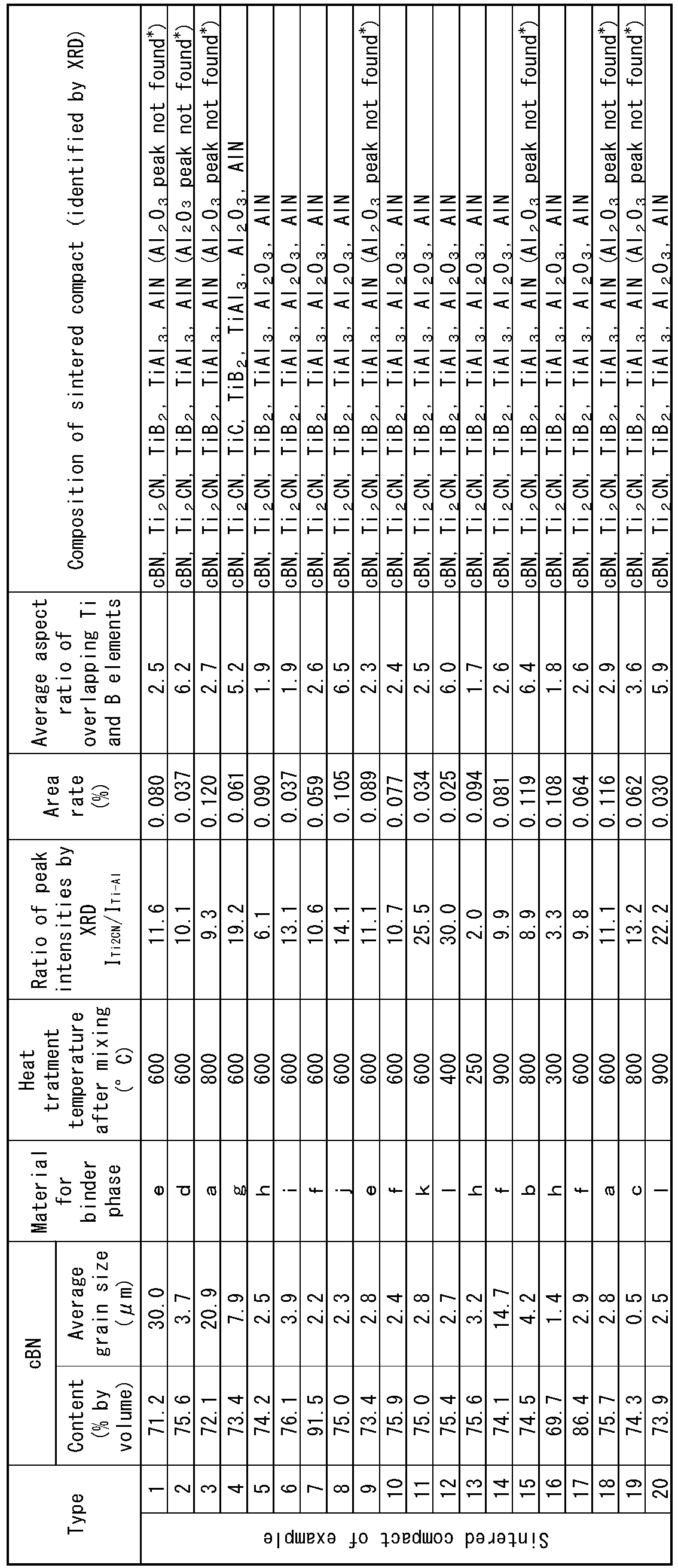
- In Table 2,the symbol *" indicates that the Al2O3 was observed by electron probe micro analyzer (EPMA).

- In Table 3, the symbol "-" indicates that it is not compounded


- In Table 4, the symbol *1" indicates that the TiAl3 was not observed by XRD, and the symbol "*2" indicates that Al2O3 was observed by electron probe micro analyzer (EPMA).
- Example tools 1 to 20 (referred to as Examples 1 to 20) and Comparative tools 1 to 8 (referred to as Comparative Examples 1 to 8) having ISO standard RNGN090300 geometry were fabricated from Inventive sintered compacts 1 to 15 and Comparative sintered compacts 1 to 5, respectively, and were each mounted on an NC lathe for the following wet cutting tests.
-
- Cutting speed: 150 m/min
- Depth of cut: 0.3 mm
- Feed rate: 0.1 mm/rev
- Workpiece material to be cut: granite (from Takine) Shape Φ150 mm by 200 mm L
- Cutting fluid material: water-soluble cutting oil (Neocool by MORESCO Co., Ltd.)
- The amount of wear of the cutting edge and the state of the cutting edge were checked after the cutting length (cutting distance) reached 800 m. Regardless of this, the cutting edge was observed every 100 m of cutting length to observe any defect and the amount of wear. If the amount of wear exceeded 2000 µm, the cutting test was stopped at that point. The results are shown in Table 5.


- In Table 5, the symbol "*" indicates the state at a cutting length of 100 m.
- Table 5 evidentially demonstrates that all Examples show reduced amount of wear and no chipping indicating high abrasive wear resistance, and also are resistant to damage factors, such as fracture due to impacts and vibrations to destroy rocks, even use as drilling tools. In contrast, all Comparative examples experience fracture or a high amount of wear after only a short cutting length, and thus have low abrasion resistance, which results indicate that they are difficult to use as drilling tools.
- The disclosed embodiments are illustrative only and not restrictive in all respects. The scope of the invention is indicated by the claims rather than the aforementioned embodiments and is intended to include all modifications within the gist and scope of the claims and equivalents
Claims (1)
- A cBN sintered compact comprising:
cubic boron nitride grains and a binder phase, wherein1) the binder phase comprises a Ti-Al alloy containing at least one element selected from the group consisting of Si, Mg, and Zn, and further comprises Ti2CN and TiB2;2) the ratio ITi2CN/ITi-Al in XRD is 2.0 or more and 30.0 or less where ITi2CN represents the peak intensity of Ti2CN appearing at 2θ from 41.9° to 42.2° and ITi-Al represents the peak intensity of the Ti-Al alloy at 2θ angle from 39.0° to 39.3°;3) areas where Ti and B elements overlap have an average aspect ratio of 1.7 or more and 6.5 or less and an area rate of 0.025% or more and 0.120% or less, in a mapping image of the Ti and B elements by Auger electron spectroscopy.
Applications Claiming Priority (2)
| Application Number | Priority Date | Filing Date | Title |
|---|---|---|---|
| JP2021014845 | 2021-02-02 | ||
| PCT/JP2022/002412 WO2022168655A1 (en) | 2021-02-02 | 2022-01-24 | Sintered cbn |
Publications (2)
| Publication Number | Publication Date |
|---|---|
| EP4289987A1 true EP4289987A1 (en) | 2023-12-13 |
| EP4289987A4 EP4289987A4 (en) | 2025-01-01 |
Family
ID=82741732
Family Applications (1)
| Application Number | Title | Priority Date | Filing Date |
|---|---|---|---|
| EP22749530.6A Pending EP4289987A4 (en) | 2021-02-02 | 2022-01-24 | SINTERED CBN |
Country Status (4)
| Country | Link |
|---|---|
| US (1) | US12529127B2 (en) |
| EP (1) | EP4289987A4 (en) |
| JP (1) | JP7852175B2 (en) |
| WO (1) | WO2022168655A1 (en) |
Cited By (2)
| Publication number | Priority date | Publication date | Assignee | Title |
|---|---|---|---|---|
| EP4112583A4 (en) * | 2020-03-13 | 2024-04-17 | Mitsubishi Materials Corporation | HARD COMPOSITE MATERIAL |
| EP4296246A4 (en) * | 2021-02-20 | 2025-01-29 | Mitsubishi Materials Corporation | Cbn sintered body |
Families Citing this family (1)
| Publication number | Priority date | Publication date | Assignee | Title |
|---|---|---|---|---|
| US20260062355A1 (en) * | 2024-09-02 | 2026-03-05 | Sumitomo Electric Hardmetal Corp. | Cubic boron nitride sintered material and tool |
Family Cites Families (24)
| Publication number | Priority date | Publication date | Assignee | Title |
|---|---|---|---|---|
| JPS6058432B2 (en) | 1976-07-16 | 1985-12-19 | ジェイエスアール株式会社 | Interval pulse generator corresponding to logarithmic value of time |
| DE3012199C2 (en) | 1979-03-29 | 1986-08-07 | Sumitomo Electric Industries, Ltd., Osaka | Boron nitride sintered body having a matrix of MC? X?, MN? X? and / or M (CN)? x? and Al and its uses |
| JPS56156738A (en) * | 1981-03-16 | 1981-12-03 | Sumitomo Electric Ind Ltd | Sintered body for high hardness tool and its manufacture |
| JPS61146763A (en) * | 1984-12-17 | 1986-07-04 | 三菱マテリアル株式会社 | Manufacture of sintered body for cutting tool |
| JPS61201751A (en) | 1985-03-04 | 1986-09-06 | Nippon Oil & Fats Co Ltd | High hardness sintered body and its manufacture |
| JP3132843B2 (en) | 1991-04-23 | 2001-02-05 | 東芝タンガロイ株式会社 | High toughness high pressure phase boron nitride sintered body |
| JPH07172919A (en) * | 1993-12-21 | 1995-07-11 | Kyocera Corp | Titanium compound sintered body |
| JP3275566B2 (en) | 1994-08-31 | 2002-04-15 | 凸版印刷株式会社 | Set of spout and cap for liquid container |
| JPH10114575A (en) | 1996-10-04 | 1998-05-06 | Sumitomo Electric Ind Ltd | High hardness sintered body for tools |
| US6265337B1 (en) | 1998-12-04 | 2001-07-24 | Sumitomo Electric Industries, Ltd. | High strength sintered body |
| US6331497B1 (en) * | 1999-07-27 | 2001-12-18 | Smith International, Inc. | Polycrystalline cubic boron nitride cutting tool |
| KR101226422B1 (en) * | 2004-10-29 | 2013-01-24 | 엘리먼트 씩스 (프로덕션) (피티와이) 리미티드 | Cubic boron nitride compact |
| US20070032369A1 (en) | 2005-08-03 | 2007-02-08 | Franzen Jan M | High content CBN materials, compact incorporating the same and methods of making the same |
| US9028573B2 (en) | 2010-09-08 | 2015-05-12 | Element Six Limited | EDM cuttable, high cBN content solid PCBN compact |
| JP5804448B2 (en) | 2012-02-28 | 2015-11-04 | 三菱マテリアル株式会社 | Cubic boron nitride based ultra-high pressure sintered body, cutting tool using this as a tool base, and surface-coated cutting tool |
| JP5663814B2 (en) * | 2013-07-03 | 2015-02-04 | 住友電工ハードメタル株式会社 | Surface coated boron nitride sintered body tool |
| JP6637664B2 (en) * | 2014-03-28 | 2020-01-29 | 三菱マテリアル株式会社 | Cubic boron nitride sintered compact cutting tool |
| JP2017179620A (en) * | 2016-03-28 | 2017-10-05 | 京セラ株式会社 | Fiber guide |
| JP2019077576A (en) | 2017-10-23 | 2019-05-23 | 島根県 | Method for improving resistance to high temperature reaction of sialon material, method for producing sialon material using the same, and sialon ceramics tool |
| KR20210007430A (en) | 2019-07-11 | 2021-01-20 | 최재영 | An electric generator |
| US20220289633A1 (en) * | 2019-07-18 | 2022-09-15 | Sumitomo Electric Industries, Ltd. | Cubic boron nitride sintered material and cutting tool |
| CN115279714B (en) * | 2020-03-13 | 2023-11-03 | 三菱综合材料株式会社 | cBN sintered body |
| JP2025146763A (en) | 2024-03-21 | 2025-10-03 | 株式会社未来造形 | Chain cleaning tool |
| JP2025156738A (en) | 2024-04-02 | 2025-10-15 | キヤノン株式会社 | distance measuring device |
-
2022
- 2022-01-24 EP EP22749530.6A patent/EP4289987A4/en active Pending
- 2022-01-24 US US18/263,306 patent/US12529127B2/en active Active
- 2022-01-24 JP JP2022579450A patent/JP7852175B2/en active Active
- 2022-01-24 WO PCT/JP2022/002412 patent/WO2022168655A1/en not_active Ceased
Cited By (3)
| Publication number | Priority date | Publication date | Assignee | Title |
|---|---|---|---|---|
| EP4112583A4 (en) * | 2020-03-13 | 2024-04-17 | Mitsubishi Materials Corporation | HARD COMPOSITE MATERIAL |
| US12534413B2 (en) | 2020-03-13 | 2026-01-27 | Mitsubishi Materials Corporation | Hard composite material |
| EP4296246A4 (en) * | 2021-02-20 | 2025-01-29 | Mitsubishi Materials Corporation | Cbn sintered body |
Also Published As
| Publication number | Publication date |
|---|---|
| JPWO2022168655A1 (en) | 2022-08-11 |
| EP4289987A4 (en) | 2025-01-01 |
| US20240318286A1 (en) | 2024-09-26 |
| US12529127B2 (en) | 2026-01-20 |
| JP7852175B2 (en) | 2026-04-28 |
| WO2022168655A1 (en) | 2022-08-11 |
Similar Documents
| Publication | Publication Date | Title |
|---|---|---|
| US12529127B2 (en) | CBN sintered body | |
| US12534413B2 (en) | Hard composite material | |
| JP6853951B2 (en) | cBN sintered body and cutting tool | |
| EP1831130B1 (en) | Method of making a powder suitable for manufacturing a cubic boron nitride compact | |
| JP7730474B2 (en) | rigid composite material | |
| JP2021151943A (en) | cBN sintered body and cutting tool | |
| EP4296246A1 (en) | Cbn sintered body | |
| JP7598089B2 (en) | cBN sintered body and cutting tool | |
| EP4286554A1 (en) | Cbn sintered compact | |
| JP7377463B2 (en) | cBN sintered body and cutting tools | |
| CN111801304B (en) | cBN sintered body and cutting tools | |
| JP6933017B2 (en) | Cubic boron nitride base sintered body and cutting tool | |
| JP7590695B2 (en) | cBN sintered body | |
| JP2024124819A (en) | cBN sintered body | |
| WO2022210760A1 (en) | Drilling tip and drilling tool | |
| JP2021143105A (en) | Hard composite material | |
| JP2020001990A (en) | cBN sintered body and cutting tool | |
| JP2020059621A (en) | Cubic boron nitride based sintered body and cutting tool |
Legal Events
| Date | Code | Title | Description |
|---|---|---|---|
| STAA | Information on the status of an ep patent application or granted ep patent |
Free format text: STATUS: THE INTERNATIONAL PUBLICATION HAS BEEN MADE |
|
| PUAI | Public reference made under article 153(3) epc to a published international application that has entered the european phase |
Free format text: ORIGINAL CODE: 0009012 |
|
| STAA | Information on the status of an ep patent application or granted ep patent |
Free format text: STATUS: REQUEST FOR EXAMINATION WAS MADE |
|
| 17P | Request for examination filed |
Effective date: 20230828 |
|
| AK | Designated contracting states |
Kind code of ref document: A1 Designated state(s): AL AT BE BG CH CY CZ DE DK EE ES FI FR GB GR HR HU IE IS IT LI LT LU LV MC MK MT NL NO PL PT RO RS SE SI SK SM TR |
|
| DAV | Request for validation of the european patent (deleted) | ||
| DAX | Request for extension of the european patent (deleted) | ||
| A4 | Supplementary search report drawn up and despatched |
Effective date: 20241204 |
|
| RIC1 | Information provided on ipc code assigned before grant |
Ipc: C04B 35/5831 20060101ALI20241128BHEP Ipc: C22C 26/00 20060101ALI20241128BHEP Ipc: B22F 5/00 20060101ALI20241128BHEP Ipc: C22C 1/051 20230101ALI20241128BHEP Ipc: C04B 35/645 20060101ALI20241128BHEP Ipc: C04B 35/5835 20060101ALI20241128BHEP Ipc: C22C 29/16 20060101AFI20241128BHEP |