EP4289253B1 - Vorrichtung zur behandlung von pflanzenstengeln mit samenkapseln - Google Patents
Vorrichtung zur behandlung von pflanzenstengeln mit samenkapseln Download PDFInfo
- Publication number
- EP4289253B1 EP4289253B1 EP23175744.4A EP23175744A EP4289253B1 EP 4289253 B1 EP4289253 B1 EP 4289253B1 EP 23175744 A EP23175744 A EP 23175744A EP 4289253 B1 EP4289253 B1 EP 4289253B1
- Authority
- EP
- European Patent Office
- Prior art keywords
- mill
- plant stems
- capsules
- processing device
- stems
- Prior art date
- Legal status (The legal status is an assumption and is not a legal conclusion. Google has not performed a legal analysis and makes no representation as to the accuracy of the status listed.)
- Active
Links
Images


Classifications
-
- A—HUMAN NECESSITIES
- A01—AGRICULTURE; FORESTRY; ANIMAL HUSBANDRY; HUNTING; TRAPPING; FISHING
- A01D—HARVESTING; MOWING
- A01D45/00—Harvesting of standing crops
- A01D45/30—Harvesting of standing crops of grass-seeds or like seeds
Definitions
- the present invention relates to a device for treating plant stems, in particular flax, which may be in the form of windrows and comprising capsules containing the seeds.
- the present invention relates in particular to the step of separating the capsules, in particular burst capsules, from the plant stems on which they are located.
- Flax is a fiber plant. To facilitate the extraction of fibers for use in the textile industry, flax stalks are retting. This operation requires that during the flax harvest, after the stalks have been pulled out, they are placed on the ground in the form of windrows, consisting of a continuous layer of parallel stalks aligned in a direction perpendicular to the movement of the pulling machine. The windrow is left in the field for a sufficient time for the microorganisms present in the soil to carry out the biological degradation of the pectic cements that bind the fibers together. When this degradation is sufficient, the flax is collected for scutching, i.e., to be processed in an industrial site for the extraction of the fibers and their cleaning for use in the textile industry.
- Biological degradation depends on the humidity and sunlight conditions to which the stems are exposed. It is understood that these conditions can vary depending on whether the stem part is facing the ground or the sky. This is why, during retting, an operation is carried out consisting of turning the windrow over in the field.
- This operation is carried out by a machine, self-propelled or towed, which has collection means capable of removing the windrow from the ground. in the form of a continuous sheet, turning means capable of turning said collected sheet back on itself and spreading means capable of spreading the sheet thus turned over on the ground.
- a machine is for example described in the document FR.2.484.768 .
- flax processing also includes the recovery of the seed grains present on the stems.
- seed grains are present in hulls, called capsules, present at the end of the flax stems. Seed grains are recovered only from a small part of the production. Seed recovery is carried out only a few days after the stems are pulled up, during a turning stage, when the seeds have finished their maturation but have not yet been or have been too degraded by retting.
- the capsules of the flax stems can be treated to allow the recovery of the seeds found there, without damaging the stems intended to be scutched later.
- decapsulators For this purpose, it is known to use self-propelled or trailed machines, called decapsulators, to recover the seeds contained in the capsules.
- decapsulators generally comprise collection means for recovering the flax stems present on the ground in the form of a windrow, then means for processing said flax stems.
- the upper, or apical, part of the stems in which the capsules are located is split and crushed, for example by passing through a slot of defined dimensions, then between two adjacent crushing rollers, so as to obtain a splitting and a crushing of the capsules.
- the apical part of the stems is beaten, by passing through a beater, before the split capsules and the seeds still remaining on the stems are separated from the stems.
- the stems are separated to recover only the seeds, while the stems are spread on the ground in the form of a windrow.
- the separation of the burst capsules and the stems is carried out using rollers, or mills, arranged parallel to the plane of the sheet of stems, with a front end located towards the middle of the stems, and a rear end located beyond the apical part of the stems, so as to push the burst capsules and the seeds present on the surface of the stems, beyond said edge of the stems.
- the rollers may comprise, on their surface, scraping elements intended to scrape the surface of the plant stems, and are rotated around their longitudinal axis, so that their surface moves from the center of the stems towards said edge of the stems when they are in contact with the stems.
- Capsule separation devices are notably described in the documents FR 2 646 587 , FR 2 562 916 , FR 829 239 or even BE 424 702 .
- plant stems and in particular flax, are formed from a multitude of fibrous bundles, often fine, which can become entangled on rotating elements or other devices for processing plant stems.
- plant stem fibers it is common for plant stem fibers to become wrapped around rotating rollers, and in particular around the rotation bearings via which the rollers are mounted in rotation on the processing device, which can lead to entanglement and therefore wear or, worse, blockages of said rollers or even heating which can lead to fires.
- the present invention aims to solve the various technical problems stated above.
- the present invention aims to provide a device for treating plant stems comprising capsules, which is less sensitive to the fibers present on the surface of the plant stems.
- the present invention aims to provide a device for treating plant stems comprising capsules, which limits the winding and accumulation of fibers during the separation of the capsules and the plant stems.
- a device for treating plant stems comprising seed capsules, in particular burst ones, according to claim 1.
- the fibers of the plant stems can only very hardly wind up there and become entangled there. Indeed, the absence of a rotation bearing at the front end of the first mill reduces the risks of snagging and accumulation of fibers of the plant stems at this particular location.
- the first mill is held by its rear end, which leaves the front end completely free and which allows it to be made or conform adequately to limit the points of attachment of plant stem fibers. Thanks to such a free front end, the risks of winding and entanglement are therefore limited, and therefore the risks of damage, wear or even blockage of the first mill, which would reduce the performance and profitability of the treatment device and could even lead to fire risks.
- the device comprises conveying means configured to convey the plant stems, in a first direction, in the form of a continuous sheet extending in a plane.
- the front end of the first mill is a rounded end, preferably smooth, for example a convex end such as a cone.
- the front end of the first mill is designed to limit the points of attachment and to facilitate the sliding of the fibers therein.
- the front end of the first mill is chosen to be rounded, and preferably smooth, so as not to form an obstacle to the movement of the fibers thereon, but on the contrary, so as to allow the sliding of the fibers and their entrainment by the rest of the continuous sheet of plant stems circulating in the treatment device.
- the first mill is mounted on the processing device frame by its rear end.
- the first mill is thus always held along its longitudinal axis, but only on the rear side, and not by the two ends, so as to keep the front end free.
- holding the first mill by its rear end allows for easier rotational drive and limits, on the rear side, any possible entanglements or snagging of the apical end of the plant stem fibers.
- the processing device comprises a motor mounted between the frame and the first mill in order to rotate the first mill on itself, and the part of the motor integral with the first mill, in this case the rotor of the motor, is mounted inside the first mill, preferably substantially in the middle of the first mill and more preferably close to the center of gravity of the first mill.
- the stator of the motor is mounted inside the first mill, preferably substantially in the middle of the first mill and more preferably close to the center of gravity of the first mill.
- the motor itself i.e. the stator and the rotor, is mounted inside the first mill, preferably substantially in the middle of the first mill and more preferably close to the center of gravity of the first mill.
- the first roller is mounted to rotate, in particular around its longitudinal axis, so as to accentuate the sweeping of the surface of the plant stems.
- the rotational drive of the first mill relative to the treatment device is carried out via a motor.
- the first mill is secured to the drive motor by a portion located inside the first mill, and ideally close to the center of gravity of the first mill. It is thus possible to obtain a stable drive and limit the mechanical stresses at the level of the securing connection between the first mill and its drive motor. Such a configuration makes it possible to obtain a first mill that is more robust over time, and less subject to deformation.
- the first mill also comprises scraping means mounted on the peripheral surface of the body, the scraping means extending substantially between the front end and the rear end of the first mill, for example in a longitudinal direction or in a helical shape, and each comprising a front end and a rear end.
- the scraping means are the elements of the first mill that will come into direct contact with the plant stems to scrape their surface in order to separate the burst capsules and the seeds present there.
- the scraping means are therefore essential elements of the processing device, but also elements that are likely to wear out over time.
- the scraping means are removably mounted on the peripheral surface of the body of the first mill, for example by lateral clamping, preferably between their front and rear ends, and/or by holding at their front and rear ends.
- the scraping means are thus designed to be dismantled from the first mill, in particular when they are too worn and need to be replaced. It is thus possible to change only part of the first mill, all or part of the scraping means, and not the entire first mill, when the latter is worn after a given period of use.
- the rest of the first mill can be kept identical, in particular the body, the connection with the drive motor or the first smooth end, which limits the maintenance costs of the first mill and the arduousness of the maintenance work.
- the first mill comprises a cone, preferably smooth, mounted on the front end of the first mill, for example at the front end of the body of the first mill, and covering, at least partially, the interface between the scraping means and the peripheral surface of the body of the first mill at the front end.
- the first mill may comprise a front end which covers the front end of the scraping means.
- a front end which covers the front end of the scraping means.
- the cone therefore makes it possible on the one hand to prevent the fibers from catching or winding on the first mill, but also on the scraping means.
- the cone also makes it possible to improve the mechanical mounting of the latter on the body of the first mill, in particular at the front end of the first mill.
- the first mill is mounted on the frame via a tilting means configured to tilt the longitudinal axis of the first mill relative to the plane of the continuous sheet of plant stems, preferably so as to move the front end of the first mill and the continuous sheet away from each other.
- a tilting means configured to tilt the longitudinal axis of the first mill relative to the plane of the continuous sheet of plant stems, preferably so as to move the front end of the first mill and the continuous sheet away from each other.
- the first mill is mounted on the frame via a sliding means configured to allow vertical movement of the first mill relative to the plane of the continuous layer of plant stems.
- the first mill is mounted pivoting and/or sliding on the frame of the treatment device, in particular vertically, so as to allow the first mill to move away from the continuous layer of plant stems.
- Such pivoting and/or sliding can precisely allow said foreign body or said pile to pass without creating mechanical stress in the treatment device, in particular at the connection between the first mill and the frame.
- the first mill since the first mill is mounted on the frame only by its rear end, it is sufficient to provide a pivoting and/or sliding mechanism between it and the frame, to obtain the desired pivoting and/or sliding of the first mill.
- the treatment device further comprises a second mill identical to the first mill, the first and second mills being arranged on either side of the plane of the continuous sheet of plant stems, and at least a portion of the second mill extends substantially parallel to the plane of the continuous sheet.
- the two mills are preferably parallel to each other and simultaneously sweep the upper and lower surfaces of the continuous layer of plant stems, so as to remove the capsules and seeds present.
- the first and/or second mill is mounted on the frame via a controlled spacing means, configured to modify the distance between the first mill and the second mill by translation of the first and/or second mill, preferably so as to modify the spacing between the first and second mills at the continuous sheet level.
- the two mills are mounted on the chassis only by their rear end, it is sufficient to provide a translation mechanism between them and the chassis, to obtain the desired spacing between the first and second mills, while keeping the two mills parallel to each other.
- Such a modification of the spacing of the two mills can be used in particular when the layer becomes thicker, for example due to a more rapid accumulation of plant stems at the level of the collection means. Increasing the spacing between the two mills can then allow better scraping of the surfaces of the layer of plant stems, without however dragging the plant stems along with the capsules and seeds.
- the spacing means is controlled, so that the spacing between the two mills can be chosen.
- a machine, self-propelled or towed comprising a decapsulating system, or decapper, comprising a device for treating plant stems as described previously, for sweeping the surface of the plant stems comprising seed capsules, in particular burst ones.
- the treatment device can therefore be integrated into an agricultural machine including a decapping system.
- the machine comprises conveying means configured to convey, in a first direction, the plant stems between the different treatment devices of the machine, in the form of a continuous sheet extending in a plane.
- said treatment device is mounted, in said decapsulating system and in the direction of conveyance of the seeds, downstream of a device for crushing and bursting the capsules of plant stems, and upstream of a separation device, so as to successively break the capsules of the plant stems, separate said broken capsules from the plant stems and isolate the seeds from the rest of the capsules, said operations being carried out continuously while the machine is moving.
- the processing device is positioned after the capsule crushing and bursting means, in order to separate the burst capsules and seeds on the one hand, and the plant stems on the other.
- the machine also comprises collection means and spreading means, said treatment device being mounted downstream of the collection means and upstream of the spreading means, so as to successively collect the plant stems, for example at least one windrow, treat the plant stems and spread the plant stems, said operations being carried out continuously while the machine is moving.
- collection means and spreading means said treatment device being mounted downstream of the collection means and upstream of the spreading means, so as to successively collect the plant stems, for example at least one windrow, treat the plant stems and spread the plant stems, said operations being carried out continuously while the machine is moving.
- the decapsulating system can be mounted on various types of agricultural machinery, including windrow turning machines configured to collect, turn and spread the plant stems in the form of a windrow on the ground.
- the decapsulating system can be mounted after collecting, and possibly turning, the plant stems, and before spreading the plant stems, freed from their capsules, on the ground.
- FIGS. 1 and 2 represent, in perspective and in section, views of a mill 1 for a treatment device 2 as illustrated in the figures 3 to 6 .
- the mill 1 has a generally longitudinal shape with a front end 4 and a rear end 6, and extends around a longitudinal axis A.
- the mill 1 comprises a body 8, for example of generally cylindrical or conical shape, with a peripheral surface 10, or peripheral wall, and scraping means 12 mounted on the peripheral surface 10 of the body 8.
- a cone 14 is provided at the front end 4 of the mill 1, while the rear end 6 is configured to allow the mill 1 to be mounted on a frame 16 (see figures 3 to 6 ).
- the mill 1 is intended to separate capsules and seeds present on the surface of a continuous layer of plant stems.
- the layer of plant stems for example a windrow collected by a suitable collection device, is conveyed in a direction D (see Figure 6 ) along different devices allowing treatment of the plant stems, such as: their turning and/or their decapsulating.
- the plant stems are oriented substantially perpendicular to the direction D.
- the mills 1 come in particular to sweep the surface of the continuous sheet of plant stems with the scraping means 12, so as to push the capsules and seeds beyond the apical part of the plant stems, and make them fall towards another device, for example configured to separate the capsules and the seeds.
- the scraping means 12 are mounted on the peripheral surface 10 of the body 8 of the mill 1, and form a part of the peripheral surface of the mill 1.
- the scraping means 12 are intended to come directly into contact with the plant stems, the surface of which they sweep, when the mill 1 rotates. rotating around its axis.
- the scraping means 12 extend between the front end 4 and the rear end 6 of the mill 1, and may thus comprise a front end 18 arranged near the front end 4 of the mill 1, and a rear end 20 arranged near the rear end 6 of the mill 1.
- the scraping means 12 may in particular extend in a longitudinal direction, parallel to the longitudinal direction A of the mill 1 as illustrated in the Figures 1 and 2 , or can extend in any other form, for example helical.
- the scraping means 12 are intended to wear out during use, by friction on the plant stems, they are preferably mounted in a removable manner on the mill 1. It is then possible to replace them or repair/renovate them when they are worn or damaged, without having to change the entire mill 1.
- the scraping means 12 can be mounted on the body 8 at their ends 18, 20 and/or between their ends 18, 20.
- the rear end 20 of the scraping means may comprise a lug intended to cooperate with a corresponding housing provided at the rear end 6 of the mill 1.
- the front end 18 of the scraping means may also be configured to cooperate with the front end 4 of the mill 1, and more particularly with the cone 14 mounted at the front end 4 of the mill 1.
- the cone 14 may be provided to cover the front end 18 of the scraping means 12, and more particularly the interface between the front end 18 of the scraping means 12 and the body 8. The cone 14 thus makes it possible to prevent plant fibers from catching at this interface.
- the front end 4, in particular the cone 14, and the rear end 6 may also be configured to position and maintain the scraping means 12 along the periphery of the peripheral surface 10 of the body 8.
- the cone 14 and the rear end 6 may comprise notches for cooperation with the ends 18, 20 of the scraping means 12, so as to prevent any movement, in particular sliding, of said scraping means 12 around the peripheral surface 10 of the body 8, in particular when the mill 1 rotates around its longitudinal axis A and that the scraping means 12 are subjected to transverse forces during contact with the plant stems.
- the scraping means 12 can also be held on the peripheral surface 10 of the body 8 between their two ends 18, 20.
- the mill 1 can comprise clamping means such as clamping wedges 22 which are fixed directly to the peripheral surface 10 of the body 8, between the scraping means 12, and which pinch laterally, on either side, the scraping means 12. The clamping wedges 22 therefore contribute to holding the scraping means 12 in position and on the body 8.
- the mills 1 are thus designed to rotate around said longitudinal axis A, the latter being oriented in a plane parallel to the plane of the continuous sheet of plant stems comprising the direction D of conveyance of the plant stems, when the mill 1 has a generally cylindrical shape, but with an angle relative to the direction D of conveyance of the plant stems (see Figure 6 ).
- the longitudinal axis A may be inclined relative to the plane of the continuous layer of plant stems, so that the edge of the mill coming into contact with the plant stems is parallel to the plane of the layer of plant stems.
- a portion of the mill 1 extends substantially parallel to the plane of the continuous layer, namely the portion of the mill 1 closest to the continuous layer.
- the angle between the longitudinal direction A and the direction D is particularly provided so that the front end 4 of the mills is located near the middle of the plant stems, and so that the rear end 6 of the mills is located near or beyond the apical part of the plant stems. In this way, the capsules and seeds swept by the scraping means 12 are moved from the middle to the apical part of the plant stems as the plant stems move from the front end 4 to the rear end 6 of the mills 1.
- plant stems are therefore conveyed towards the front end 4 of the mills 1.
- plant stems in particular flax stems, comprise a multitude of fibers, sometimes very fine, some of which are likely to become wrapped around any obstacle present along their path.
- the latter comprise a front end 4 which is free, in particular which is devoid of any means of rotation such as a bearing.
- the mill 1 is mounted, on the frame 16, cantilevered above or below the continuous sheet of plant stems. The free front end of the mills 1 thus makes it possible to limit the snagging of plant fibers likely to become entangled therein, as is often the case when the mills are mounted between two bearings.
- the mill 1 comprises a smooth front end 4, facilitating the sliding of the upper fibers.
- the shape of the front end 4 is also configured to facilitate the sliding of the fibers there.
- the front end 4 of the mill 1 is chosen to be rounded in shape, and preferably convex in shape in order to guide the fibers beyond the front end 4 of the mill 1.
- the mill 1 is provided with the cone 14 mounted on the front end 4. The cone 14 makes it possible to guide the fibers to the scraping means 12, while limiting the risks of snagging or entanglement.
- the cone 14 can cover the front end 18 of the scraping means 12, and therefore the interface between the scraping means 12 and the body 8.
- the cone 14 therefore forms a cap completely covering the front end of the body 8 and guiding the plant fibers directly onto the scraping means 12.
- the cone 14 makes it possible both to limit the entanglement of the fibers on the front end of the mill 1 and to maintain the front end 18 of the scraping means 12.
- the cone 14 can be removably mounted on the body 8.
- a removable mounting of the cone 14 can in particular facilitate the changing of the scraping means 12, by allowing their removal and insertion from the front of the mill 1.
- a cone 14 removable can also facilitate the mounting and removal of the mill 1 on the chassis, in particular when the connection is provided inside the body 8, as described below. In this case, the removal of the cone 14 allows easy access to the inside of the body 8 to carry out the operations of mounting/dismounting the mill 1 on the chassis 16.
- the mill 1 is thus, in the case illustrated in the figures, mounted by its rear end 6.
- the body 8 has an open rear end allowing the body 8 to slide around an element of the chassis 16 or around an element mounted on the chassis 16.
- Such mounting by the rear end 6 of the mill 1 and by the interior of the mill 1, makes it possible, here again, to limit the areas of attachment on which fibers could become wound during the sweeping of the capsules and seeds by the treatment device 2.
- the body 8 is positioned around a motor 24 configured to rotate the mill 1 relative to the frame 16. More precisely, the body 8 is secured to the rotor 26 of the motor 24, via securing means 28, for example screws.
- the positioning of the motor 24, in particular of the stator of the motor 24, is chosen so as to be located near the middle of the mill 1, and in particular near the center of gravity of the mill 1, so as to limit the torsional stresses due to the weight of the mill 1, at the level of the securing between the body 8 and the motor 24.
- the securing means 28 are directly accessible after removal of the cone 14: once the latter has been removed, the screw heads are exposed, which allows the body 8 to be mounted on the rotor 26 of the motor 24, or on the contrary the body 8 to be dismantled. This facilitates maintenance operations on the mill 1, in particular if it is desired to replace the scraping means 12.
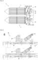
- THE figures 3 to 5 represent a side view of the treatment device 2.
- the treatment device 2 thus comprises two mills 1, 1' mounted on either side of the continuous layer of plant stems, in particular above and below said continuous layer of plant stems.
- the two mills 1, 1' are arranged substantially parallel to each other, with a spacing between them provided for the circulation of the continuous layer of plant stems.
- the mills 1 and 1' prevent the capsules and seeds from passing between them and convey them in a direction other than the plant stems, for example towards a device configured to separate the seeds from the capsules.
- At least one of the mills 1, 1' is mounted pivoting relative to the plane of the layer of plant stems, and/or sliding in the vertical direction in order to allow the end of the mill or the entire mill to be moved away from the continuous layer.
- the lower mill 1' is mounted on the frame 16 via an inclination means 30, while the upper mill 1 is mounted on the frame 16 via a spacing means 32.
- the invention is not limited to such an embodiment, and it is perfectly conceivable to provide the upper mill 1 with an inclination means instead of, or in addition to, the spacing means, or the lower mill 1' with a spacing means instead of, or in addition to, the inclination means.
- the tilting means 30 is provided between the motor 24 and the chassis 16.
- the motor 24 is mounted on the chassis 16 by a pivot connection 34 allowing pivoting, in particular of the longitudinal axis A of the mill 1', relative to a horizontal axis. Such pivoting, at the rear end 6 of the mill 1' therefore makes it possible to modify the distance separating the front end 4 of the mill 1' and the continuous layer of plant stems.
- the motor 24 is furthermore connected to the chassis via a return element 36 positioned, in this case, above the pivot connection 34 and is configured to maintain the longitudinal axis A of the mill 1' substantially parallel to the continuous layer of plant stems.
- the return element 36 may comprise a spring or an elastically deformable element, and is configured to exert a return force so as to position the mill 1' parallel to the layer of plant stems.
- the mill 1' is parallel to the layer of plant stems and allows the lower surface thereof to be swept.
- a force will then be exerted between the two mills 1, 1' to move them away from each other, which will create a force opposing the return element 36: the latter will then deform elastically under the effect of such a force in order to allow the front end 4 of the mill 1' to move away from the continuous layer of plant stems, to allow the foreign body to pass.
- the spacing means 32 is provided between the motor 24 and the chassis 16.
- the motor 24 is mounted on the chassis 16 by a sliding connection allowing sliding, in particular vertical sliding, of the mill 1. Such sliding therefore makes it possible to modify the distance separating the two mills 1, 1'.
- the motor 24 is for example mounted on the chassis 16 via two connecting rods 38: one end of each connecting rod 38 is pivotally connected to the chassis 16 and the other end is pivotally mounted on the motor 24, the pivot connections being horizontal.
- the mill 1 is parallel to the layer of plant stems and allows the upper surface thereof to be swept.
- the upper mill 1 will be able to translate vertically by rotation of the two connecting rods 38. Once the origin of the stress has disappeared, and due to its own weight, the upper mill 1 will then be brought to return to its initial position, by rotation of the two connecting rods 38 in the other direction.
- the spacing means 32 therefore offers a free movement to the upper mill 1, allowing it an upward sliding when the stresses exerted between the two mills 1, 1' are sufficient to overcome the own weight of the upper mill 1.
- the spacing means 32 can also be controlled, in order to allow direct control of the spacing between the two mills 1 and 1'.
- the spacing means 32 can comprise a piston 40 mounted between one end of one of the connecting rods 38 and the frame 16. Actuation of the piston 40 then makes it possible to pivot the two connecting rods 38, and therefore to slide the mill 1 vertically.
- the spacing means 32 may comprise a sliding connection, advantageously vertical, between the connecting rod 38 and the piston 40.
- a sliding connection allows free movement of the connecting rod 38, and therefore of the mill 1, relative to the piston 40, in particular when the mill 1 is lifted vertically by a foreign body or a mass present in the continuous sheet.
- FIG. 6 illustrates, in part, a decapping system 42 comprising two processing devices 2 according to the present invention. More particularly, the decapping system 42 can be integrated into a more complex system, for example in a windrow turning and decapping machine.
- the decapping system 42 comprises, in the present case, two lines configured to each process a continuous layer of plant stems and each comprising, in particular, a treatment device 2.
- the system therefore makes it possible to process, in parallel, two continuous layers of plant stems.
- Such a system can in particular be found in machines configured to process two windrows simultaneously.
- each line comprises conveying means 44 configured to convey the sheet of plant stems in the first direction D, between the different treatment devices.
- the conveying means 44 may be in the form of flexible mobile bands between which the plant stems are pinched to be driven between the different treatment devices.
- the decapping system 42 can be mounted downstream, in the direction of movement of the continuous sheet, of a turning device.
- the decapping system 42 comprises, firstly, means for crushing and bursting the capsules of the plant stems.
- the decapping system 42 may comprise a fixed slot (not shown) through which the capsules are forced, as well as so-called crushing rollers (not shown) which crush the capsules to reveal the seeds contained therein.
- a bursting device 46 for example in the form of a beater, may then be provided to beat the crushed stems and capsules so as to burst the capsules.
- the decapping system 42 then comprises the treatment device 2 as described previously, making it possible to separate the capsules and the seeds from the plant stems of the continuous sheet.
- the plant stems continue to be conveyed by the conveying means 44, for example to means for spreading on the ground in the form of a windrow.
- the capsules and seeds are conveyed to another separation device (not shown) allowing the separation of the capsule pieces on one side and the seeds on the other.
- the processing device it becomes possible to separate capsules and seeds from plant stems, while limiting the risks of fibers winding and entangling around the mills.
- the device according to the present invention makes it possible to improve the overall reliability of the device, while maintaining different degrees of freedom in the event of foreign bodies or jamming, and while allowing easy access and maintenance.
Landscapes
- Life Sciences & Earth Sciences (AREA)
- Environmental Sciences (AREA)
- Pretreatment Of Seeds And Plants (AREA)
- Crushing And Grinding (AREA)
- Apparatuses For Bulk Treatment Of Fruits And Vegetables And Apparatuses For Preparing Feeds (AREA)
Claims (13)
- Behandlungsvorrichtung (2) von Pflanzenstängeln, die, insbesondere aufgeplatzte, Samenkapseln aufweisen und sich in einer ersten Richtung (D) in Form einer kontinuierlichen Bahn, die sich in einer Ebene erstreckt bewegen, wobei die Vorrichtung (2) einen Rahmen (16) und eine erste Mühle (1) aufweist, die sich entlang einer Längsachse (A) zwischen einem vorderen Ende (4) und einem hinteren Ende (6) erstreckt, die erste Mühle (1) umfassend einen Körper (8) von zum Beispiel einer generell zylindrischen oder konischen Form, der eine Umfangsfläche (10) aufweist,wobei sich mindestens ein Teil der ersten Mühle (1) im Wesentlichen parallel zu der Ebene der kontinuierlichen Bahn erstreckt,wobei die Längsachse (A) der ersten Mühle (1) in Bezug auf die erste Richtung (D) geneigt ist, sodass sie über die Oberfläche der Pflanzenstängel der kontinuierlichen Bahn streicht,wobei das vordere Ende (4) der ersten Mühle (1) in der Bewegungsrichtung der Pflanzenstängelbahn stromaufwärts von dem hinteren Ende (6) positioniert ist,wobei die erste Mühle (1) auch Abstreifeinrichtungen (12) aufweist, die an der Umfangsfläche (10) des Körpers (8) angebracht sind, wobei sich die Abstreifeinrichtungen (12) im Wesentlichen zwischen dem vorderen Ende und dem hinteren Ende der ersten Mühle (1) erstrecken und jeweils ein vorderes Ende (18) und ein hinteres Ende (20) aufweisen,wobei das vordere Ende (4) der ersten Mühle (1) ein freies Ende ist und wobei die erste Mühle (1) mit ihrem hinteren Ende (6) an dem Rahmen (16) der Behandlungsvorrichtung montiert ist,dadurch gekennzeichnet, dass die Vorrichtung einen Motor (24) umfasst, der einen Rotor (26) aufweist, der zwischen dem Rahmen (16) und der ersten Mühle (1) montiert ist, um die erste Mühle (1) um sich selbst drehen zu lassen,und dass der Rotor (26) des Motors fest mit der ersten Mühle (1) verbunden ist und innerhalb der ersten Mühle (1) montiert ist.
- Behandlungsvorrichtung (2) nach Anspruch 1, wobei das vordere Ende (4) der ersten Mühle (1) ein abgerundetes, vorzugsweise glattes Ende ist, z. B. ein konvexes Ende, wie beispielsweise ein Kegel.
- Behandlungsvorrichtung (2) nach Anspruch 1 oder 2, wobei der Rotor (26) des Motors im Wesentlichen in der Mitte der ersten Mühle (1) und bevorzugter in der Nähe des Schwerpunkts der ersten Mühle (1) montiert ist.
- Behandlungsvorrichtung (2) nach einem der vorherigen Ansprüche, wobei der Stator des Motors innerhalb der ersten Mühle (1), vorzugsweise im Wesentlichen in der Mitte der ersten Mühle (1) und bevorzugter in der Nähe des Schwerpunkts der ersten Mühle (1) montiert ist.
- Behandlungsvorrichtung (2) nach einem der vorherigen Ansprüche, wobei sich die Abstreifeinrichtungen (12) in einer Längsrichtung oder in einer schraubenförmigen Form erstrecken.
- Behandlungsvorrichtung (2) nach einem der vorherigen Ansprüche, wobei die Abstreifeinrichtungen (12) lösbar an der Umfangsfläche (10) des Körpers der ersten Mühle montiert sind, z. B. durch seitliches Einklemmen, vorzugsweise zwischen ihrem vorderen und hinteren Ende, und/oder durch Halten an ihrem vorderen und hinteren Ende.
- Behandlungsvorrichtung (2) nach einem der vorherigen Ansprüche, wobei die erste Mühle einen vorzugsweise glatten Konus (14) aufweist,
der an dem vorderen Ende (4) der ersten Mühle, z. B. an dem vorderen Ende des Körpers (8) der ersten Mühle, montiert ist und die Schnittstelle zwischen den Abstreifeinrichtungen (12) und der Umfangsfläche (10) des Körpers der ersten Mühle an dem vorderen Ende zumindest teilweise abdeckt. - Behandlungsvorrichtung (2) nach einem der vorherigen Ansprüche, wobei die erste Mühle (1) über Neigungseinrichtungen (30), die konfiguriert sind, um die Längsachse (A) der ersten Mühle (1) in Bezug auf die Ebene der kontinuierlichen Bahn von Pflanzenstängeln zu neigen, vorzugsweise um das vordere Ende (4) der ersten Mühle von der kontinuierlichen Bahn weg zu bewegen, an dem Rahmen (16) montiert ist.
- Behandlungsvorrichtung (2) nach einem der vorherigen Ansprüche, die ferner eine zweite Mühle (1') aufweist, die mit der ersten Mühle (1) identisch ist, wobei die erste und die zweite Mühle (1, 1') auf beiden Seiten der Ebene der kontinuierlichen Bahn von Pflanzenstängeln angeordnet sind und wobei sich mindestens ein Teil der zweiten Mühle (1') im Wesentlichen parallel zu der Ebene der kontinuierlichen Bahn erstreckt.
- Behandlungsvorrichtung (2) nach dem vorherigen Anspruch, wobei die erste und/oder die zweite Mühle über optional gesteuerte Abstandseinrichtungen (32) an dem Rahmen (16) montiert sind, die konfiguriert sind, um den Abstand zwischen der ersten Mühle (1) und der zweiten Mühle (1') durch Translation der ersten und/oder der zweiten Mühle zu verändern, vorzugsweise, um den Abstand zwischen der ersten und der zweiten Mühle an der kontinuierlichen Bahn zu verändern.
- Maschine, selbstfahrend oder gezogen, das ein Kapselungssystem (42) aufweist, umfassend eine Behandlungsvorrichtung (2) von Pflanzenstängeln nach einem der vorherigen Ansprüche, um über die Oberfläche der Pflanzenstängel, die Samenkapseln, insbesondere aufgeplatzte Samenkapseln, aufweisen, zu streichen.
- Maschine nach dem vorherigen Anspruch, wobei die Behandlungsvorrichtung (2) in dem Kapselungssystem (42) und in der Förderrichtung der Samen stromabwärts von einer Quetsch- und Aufbrechvorrichtung (46) der Kapseln der Pflanzenstängel montiert ist, und stromaufwärts von einer Trennvorrichtung, sodass nacheinander die Kapseln der Pflanzenstängel aufgebrochen, die aufgebrochenen Kapseln von den Pflanzenstängeln getrennt und die Samen vom Rest der Kapseln isoliert werden, wobei diese Vorgänge kontinuierlich während der Bewegung des Geräts durchgeführt werden.
- Maschine nach Anspruch 11 oder 12, die auch Sammel- und Ausbreiteinrichtungen aufweist, wobei die Behandlungsvorrichtung (2) stromabwärts von den Sammeleinrichtungen und stromaufwärts von den Ausbreiteinrichtungen montiert ist, um nacheinander die Pflanzenstängel, z. B. mindestens eine Schwade, zu sammeln, die Pflanzenstängel zu behandeln und die Pflanzenstängel auszubreiten, wobei diese Vorgänge kontinuierlich während der Bewegung der Maschine durchgeführt werden.
Applications Claiming Priority (1)
| Application Number | Priority Date | Filing Date | Title |
|---|---|---|---|
| FR2205599A FR3136334B1 (fr) | 2022-06-10 | 2022-06-10 | Dispositif de traitement de tiges végétales comportant des capsules de graines |
Publications (3)
| Publication Number | Publication Date |
|---|---|
| EP4289253A1 EP4289253A1 (de) | 2023-12-13 |
| EP4289253B1 true EP4289253B1 (de) | 2025-03-19 |
| EP4289253C0 EP4289253C0 (de) | 2025-03-19 |
Family
ID=82595170
Family Applications (1)
| Application Number | Title | Priority Date | Filing Date |
|---|---|---|---|
| EP23175744.4A Active EP4289253B1 (de) | 2022-06-10 | 2023-05-26 | Vorrichtung zur behandlung von pflanzenstengeln mit samenkapseln |
Country Status (2)
| Country | Link |
|---|---|
| EP (1) | EP4289253B1 (de) |
| FR (1) | FR3136334B1 (de) |
Family Cites Families (6)
| Publication number | Priority date | Publication date | Assignee | Title |
|---|---|---|---|---|
| BE424702A (de) * | 1937-11-19 | 1937-12-31 | ||
| FR829239A (fr) * | 1937-07-23 | 1938-06-16 | Dispositif pour recueillir des fibres végétales | |
| FR2484768A1 (fr) | 1980-06-23 | 1981-12-24 | Neufville Charles | Dispositif de ramassage, retournage, etalage de lin |
| FR2562916B1 (fr) * | 1984-04-16 | 1986-10-31 | Lin Dev Sa | Machine en vue de la preparation de tiges de vegetaux produisant des fibres |
| DE3639022C1 (en) * | 1986-11-14 | 1988-04-14 | Jens Bretthauer | Self-propelled flax-harvesting machine |
| FR2646587A1 (fr) * | 1989-05-03 | 1990-11-09 | Caen Falaise Ste Coop Teillage | Machine pour l'egrenage du lin |
-
2022
- 2022-06-10 FR FR2205599A patent/FR3136334B1/fr active Active
-
2023
- 2023-05-26 EP EP23175744.4A patent/EP4289253B1/de active Active
Also Published As
| Publication number | Publication date |
|---|---|
| EP4289253A1 (de) | 2023-12-13 |
| FR3136334B1 (fr) | 2024-06-14 |
| EP4289253C0 (de) | 2025-03-19 |
| FR3136334A1 (fr) | 2023-12-15 |
Similar Documents
| Publication | Publication Date | Title |
|---|---|---|
| EP3223967B1 (de) | Abfallsortiervorrichtung mit verbessertem drehsieb | |
| EP1002467B1 (de) | Vorrichtung zum abbeeren vonTrauben vor der Weinherstellung | |
| FR2568091A1 (fr) | Appareil de recolte pour fauchage, conditionnement et andainage | |
| FR2957223A1 (fr) | Faneuse a fonctions d'andainage et d'epandage a decalage transversal | |
| FR2496395A1 (fr) | Appareil pour la preparation de chaumes coupes | |
| EP4289253B1 (de) | Vorrichtung zur behandlung von pflanzenstengeln mit samenkapseln | |
| FR2523504A1 (fr) | Tambour d'ecorcage | |
| EP0366174B1 (de) | Maschine zum Aufsammeln von auf dem Boden liegenden Früchten oder dergleichen | |
| FR2859074A1 (fr) | Egrappoir | |
| EP0308303B1 (de) | Verfahren und Vorrichtung zum Ernten von in Reihen gezüchtetem Buschholz | |
| FR2631776A1 (fr) | Procede d'eclatement des tiges de plantes fibreuses a la recolte et dispositif de mise en oeuvre | |
| FR2535165A1 (fr) | Dispositif de ramassage de la volaille | |
| EP0189017B1 (de) | Rüttelrad um Rüben zu reinigen | |
| EP3935934A1 (de) | Landwirtschaftliches gerät mit einem mähbalken und einem abnehmbaren kollektor und landwirtschaftliche maschine mit einem solchen gerät | |
| EP1722621A1 (de) | Verfahren und maschine zum ernten von faserhaltigen pflanzen, insbesondere faserflachs | |
| FR3032328A1 (fr) | Dispositif de nettoyage, tronconnage et d'epaillage des cannes a sucre | |
| FR2621777A1 (fr) | Moissonneuse pour lin vert | |
| EP0933014B1 (de) | Reinigungsvorrichtung mit integriertem Häcksler | |
| FR2737077A1 (fr) | Appareil pour distribuer des produits conditionnes en balles ou en bottes | |
| EP4272539A1 (de) | Baumaschine mit einem system zum rückführen von pflanzenstangen | |
| FR2798815A1 (fr) | Dispositif pour diminuer la tare-terre de produits agricoles notamment betteraves et machine d'arrachage equipee d'un tel dispositif | |
| EP4552469A1 (de) | Vorrichtung zum bewegen eines schwades auf dem boden | |
| FR2756458A1 (fr) | Dispositif de degrappage de moules de bouchot | |
| FR3132528A1 (fr) | Module d’écangage pour teilleuse comportant une glissière inclinée pour courroie d’entrainement. | |
| FR3140554A1 (fr) | Dispositif de collecte de particules solides contenues dans une soupe de matières organiques |
Legal Events
| Date | Code | Title | Description |
|---|---|---|---|
| PUAI | Public reference made under article 153(3) epc to a published international application that has entered the european phase |
Free format text: ORIGINAL CODE: 0009012 |
|
| STAA | Information on the status of an ep patent application or granted ep patent |
Free format text: STATUS: THE APPLICATION HAS BEEN PUBLISHED |
|
| AK | Designated contracting states |
Kind code of ref document: A1 Designated state(s): AL AT BE BG CH CY CZ DE DK EE ES FI FR GB GR HR HU IE IS IT LI LT LU LV MC ME MK MT NL NO PL PT RO RS SE SI SK SM TR |
|
| STAA | Information on the status of an ep patent application or granted ep patent |
Free format text: STATUS: REQUEST FOR EXAMINATION WAS MADE |
|
| 17P | Request for examination filed |
Effective date: 20231218 |
|
| RBV | Designated contracting states (corrected) |
Designated state(s): AL AT BE BG CH CY CZ DE DK EE ES FI FR GB GR HR HU IE IS IT LI LT LU LV MC ME MK MT NL NO PL PT RO RS SE SI SK SM TR |
|
| GRAP | Despatch of communication of intention to grant a patent |
Free format text: ORIGINAL CODE: EPIDOSNIGR1 |
|
| STAA | Information on the status of an ep patent application or granted ep patent |
Free format text: STATUS: GRANT OF PATENT IS INTENDED |
|
| INTG | Intention to grant announced |
Effective date: 20241111 |
|
| GRAS | Grant fee paid |
Free format text: ORIGINAL CODE: EPIDOSNIGR3 |
|
| GRAA | (expected) grant |
Free format text: ORIGINAL CODE: 0009210 |
|
| STAA | Information on the status of an ep patent application or granted ep patent |
Free format text: STATUS: THE PATENT HAS BEEN GRANTED |
|
| AK | Designated contracting states |
Kind code of ref document: B1 Designated state(s): AL AT BE BG CH CY CZ DE DK EE ES FI FR GB GR HR HU IE IS IT LI LT LU LV MC ME MK MT NL NO PL PT RO RS SE SI SK SM TR |
|
| REG | Reference to a national code |
Ref country code: GB Ref legal event code: FG4D Free format text: NOT ENGLISH |
|
| REG | Reference to a national code |
Ref country code: CH Ref legal event code: EP |
|
| REG | Reference to a national code |
Ref country code: IE Ref legal event code: FG4D Free format text: LANGUAGE OF EP DOCUMENT: FRENCH |
|
| REG | Reference to a national code |
Ref country code: DE Ref legal event code: R096 Ref document number: 602023002450 Country of ref document: DE |
|
| U01 | Request for unitary effect filed |
Effective date: 20250325 |
|
| U07 | Unitary effect registered |
Designated state(s): AT BE BG DE DK EE FI FR IT LT LU LV MT NL PT RO SE SI Effective date: 20250331 |
|
| U20 | Renewal fee for the european patent with unitary effect paid |
Year of fee payment: 3 Effective date: 20250327 |
|
| PG25 | Lapsed in a contracting state [announced via postgrant information from national office to epo] |
Ref country code: RS Free format text: LAPSE BECAUSE OF FAILURE TO SUBMIT A TRANSLATION OF THE DESCRIPTION OR TO PAY THE FEE WITHIN THE PRESCRIBED TIME-LIMIT Effective date: 20250619 |
|
| PG25 | Lapsed in a contracting state [announced via postgrant information from national office to epo] |
Ref country code: NO Free format text: LAPSE BECAUSE OF FAILURE TO SUBMIT A TRANSLATION OF THE DESCRIPTION OR TO PAY THE FEE WITHIN THE PRESCRIBED TIME-LIMIT Effective date: 20250619 |
|
| PG25 | Lapsed in a contracting state [announced via postgrant information from national office to epo] |
Ref country code: HR Free format text: LAPSE BECAUSE OF FAILURE TO SUBMIT A TRANSLATION OF THE DESCRIPTION OR TO PAY THE FEE WITHIN THE PRESCRIBED TIME-LIMIT Effective date: 20250319 |
|
| PG25 | Lapsed in a contracting state [announced via postgrant information from national office to epo] |
Ref country code: GR Free format text: LAPSE BECAUSE OF FAILURE TO SUBMIT A TRANSLATION OF THE DESCRIPTION OR TO PAY THE FEE WITHIN THE PRESCRIBED TIME-LIMIT Effective date: 20250620 |
|
| PG25 | Lapsed in a contracting state [announced via postgrant information from national office to epo] |
Ref country code: SM Free format text: LAPSE BECAUSE OF FAILURE TO SUBMIT A TRANSLATION OF THE DESCRIPTION OR TO PAY THE FEE WITHIN THE PRESCRIBED TIME-LIMIT Effective date: 20250319 |
|
| PG25 | Lapsed in a contracting state [announced via postgrant information from national office to epo] |
Ref country code: ES Free format text: LAPSE BECAUSE OF FAILURE TO SUBMIT A TRANSLATION OF THE DESCRIPTION OR TO PAY THE FEE WITHIN THE PRESCRIBED TIME-LIMIT Effective date: 20250319 |
|
| PG25 | Lapsed in a contracting state [announced via postgrant information from national office to epo] |
Ref country code: PL Free format text: LAPSE BECAUSE OF FAILURE TO SUBMIT A TRANSLATION OF THE DESCRIPTION OR TO PAY THE FEE WITHIN THE PRESCRIBED TIME-LIMIT Effective date: 20250319 |
|
| PG25 | Lapsed in a contracting state [announced via postgrant information from national office to epo] |
Ref country code: CZ Free format text: LAPSE BECAUSE OF FAILURE TO SUBMIT A TRANSLATION OF THE DESCRIPTION OR TO PAY THE FEE WITHIN THE PRESCRIBED TIME-LIMIT Effective date: 20250319 |
|
| PG25 | Lapsed in a contracting state [announced via postgrant information from national office to epo] |
Ref country code: SK Free format text: LAPSE BECAUSE OF FAILURE TO SUBMIT A TRANSLATION OF THE DESCRIPTION OR TO PAY THE FEE WITHIN THE PRESCRIBED TIME-LIMIT Effective date: 20250319 |
|
| PG25 | Lapsed in a contracting state [announced via postgrant information from national office to epo] |
Ref country code: IS Free format text: LAPSE BECAUSE OF FAILURE TO SUBMIT A TRANSLATION OF THE DESCRIPTION OR TO PAY THE FEE WITHIN THE PRESCRIBED TIME-LIMIT Effective date: 20250719 |