EP4286816B1 - Battery pressure measuring sensor and battery pressure measuring apparatus including the same - Google Patents
Battery pressure measuring sensor and battery pressure measuring apparatus including the same Download PDFInfo
- Publication number
- EP4286816B1 EP4286816B1 EP22904508.3A EP22904508A EP4286816B1 EP 4286816 B1 EP4286816 B1 EP 4286816B1 EP 22904508 A EP22904508 A EP 22904508A EP 4286816 B1 EP4286816 B1 EP 4286816B1
- Authority
- EP
- European Patent Office
- Prior art keywords
- battery
- variable resistor
- pressure measuring
- location
- measuring sensor
- Prior art date
- Legal status (The legal status is an assumption and is not a legal conclusion. Google has not performed a legal analysis and makes no representation as to the accuracy of the status listed.)
- Active
Links
Images


Classifications
-
- G—PHYSICS
- G01—MEASURING; TESTING
- G01L—MEASURING FORCE, STRESS, TORQUE, WORK, MECHANICAL POWER, MECHANICAL EFFICIENCY, OR FLUID PRESSURE
- G01L1/00—Measuring force or stress, in general
- G01L1/20—Measuring force or stress, in general by measuring variations in ohmic resistance of solid materials or of electrically-conductive fluids; by making use of electrokinetic cells, i.e. liquid-containing cells wherein an electrical potential is produced or varied upon the application of stress
-
- G—PHYSICS
- G01—MEASURING; TESTING
- G01L—MEASURING FORCE, STRESS, TORQUE, WORK, MECHANICAL POWER, MECHANICAL EFFICIENCY, OR FLUID PRESSURE
- G01L19/00—Details of, or accessories for, apparatus for measuring steady or quasi-steady pressure of a fluent medium insofar as such details or accessories are not special to particular types of pressure gauges
- G01L19/06—Means for preventing overload or deleterious influence of the measured medium on the measuring device or vice versa
-
- G—PHYSICS
- G01—MEASURING; TESTING
- G01L—MEASURING FORCE, STRESS, TORQUE, WORK, MECHANICAL POWER, MECHANICAL EFFICIENCY, OR FLUID PRESSURE
- G01L1/00—Measuring force or stress, in general
- G01L1/20—Measuring force or stress, in general by measuring variations in ohmic resistance of solid materials or of electrically-conductive fluids; by making use of electrokinetic cells, i.e. liquid-containing cells wherein an electrical potential is produced or varied upon the application of stress
- G01L1/22—Measuring force or stress, in general by measuring variations in ohmic resistance of solid materials or of electrically-conductive fluids; by making use of electrokinetic cells, i.e. liquid-containing cells wherein an electrical potential is produced or varied upon the application of stress using resistance strain gauges
-
- G—PHYSICS
- G01—MEASURING; TESTING
- G01B—MEASURING LENGTH, THICKNESS OR SIMILAR LINEAR DIMENSIONS; MEASURING ANGLES; MEASURING AREAS; MEASURING IRREGULARITIES OF SURFACES OR CONTOURS
- G01B7/00—Measuring arrangements characterised by the use of electric or magnetic techniques
- G01B7/16—Measuring arrangements characterised by the use of electric or magnetic techniques for measuring the deformation in a solid, e.g. by resistance strain gauge
-
- G—PHYSICS
- G01—MEASURING; TESTING
- G01L—MEASURING FORCE, STRESS, TORQUE, WORK, MECHANICAL POWER, MECHANICAL EFFICIENCY, OR FLUID PRESSURE
- G01L19/00—Details of, or accessories for, apparatus for measuring steady or quasi-steady pressure of a fluent medium insofar as such details or accessories are not special to particular types of pressure gauges
-
- G—PHYSICS
- G01—MEASURING; TESTING
- G01L—MEASURING FORCE, STRESS, TORQUE, WORK, MECHANICAL POWER, MECHANICAL EFFICIENCY, OR FLUID PRESSURE
- G01L9/00—Measuring steady of quasi-steady pressure of fluid or fluent solid material by electric or magnetic pressure-sensitive elements; Transmitting or indicating the displacement of mechanical pressure-sensitive elements, used to measure the steady or quasi-steady pressure of a fluid or fluent solid material, by electric or magnetic means
- G01L9/02—Measuring steady of quasi-steady pressure of fluid or fluent solid material by electric or magnetic pressure-sensitive elements; Transmitting or indicating the displacement of mechanical pressure-sensitive elements, used to measure the steady or quasi-steady pressure of a fluid or fluent solid material, by electric or magnetic means by making use of variations in ohmic resistance, e.g. of potentiometers, electric circuits therefor, e.g. bridges, amplifiers or signal conditioning
-
- H—ELECTRICITY
- H01—ELECTRIC ELEMENTS
- H01M—PROCESSES OR MEANS, e.g. BATTERIES, FOR THE DIRECT CONVERSION OF CHEMICAL ENERGY INTO ELECTRICAL ENERGY
- H01M10/00—Secondary cells; Manufacture thereof
- H01M10/42—Methods or arrangements for servicing or maintenance of secondary cells or secondary half-cells
- H01M10/48—Accumulators combined with arrangements for measuring, testing or indicating the condition of cells, e.g. the level or density of the electrolyte
-
- G—PHYSICS
- G01—MEASURING; TESTING
- G01L—MEASURING FORCE, STRESS, TORQUE, WORK, MECHANICAL POWER, MECHANICAL EFFICIENCY, OR FLUID PRESSURE
- G01L19/00—Details of, or accessories for, apparatus for measuring steady or quasi-steady pressure of a fluent medium insofar as such details or accessories are not special to particular types of pressure gauges
- G01L2019/0053—Pressure sensors associated with other sensors, e.g. for measuring acceleration, temperature
-
- H—ELECTRICITY
- H01—ELECTRIC ELEMENTS
- H01M—PROCESSES OR MEANS, e.g. BATTERIES, FOR THE DIRECT CONVERSION OF CHEMICAL ENERGY INTO ELECTRICAL ENERGY
- H01M2200/00—Safety devices for primary or secondary batteries
- H01M2200/20—Pressure-sensitive devices
-
- Y—GENERAL TAGGING OF NEW TECHNOLOGICAL DEVELOPMENTS; GENERAL TAGGING OF CROSS-SECTIONAL TECHNOLOGIES SPANNING OVER SEVERAL SECTIONS OF THE IPC; TECHNICAL SUBJECTS COVERED BY FORMER USPC CROSS-REFERENCE ART COLLECTIONS [XRACs] AND DIGESTS
- Y02—TECHNOLOGIES OR APPLICATIONS FOR MITIGATION OR ADAPTATION AGAINST CLIMATE CHANGE
- Y02E—REDUCTION OF GREENHOUSE GAS [GHG] EMISSIONS, RELATED TO ENERGY GENERATION, TRANSMISSION OR DISTRIBUTION
- Y02E60/00—Enabling technologies; Technologies with a potential or indirect contribution to GHG emissions mitigation
- Y02E60/10—Energy storage using batteries
Definitions
- the present disclosure relates to a battery pressure measuring sensor and a battery pressure measuring apparatus including the same, and more particularly, to a sensor capable of measuring the pressure of a battery and a battery pressure measuring apparatus including the same.
- Batteries commercially available at present include nickel-cadmium batteries, nickel hydrogen batteries, nickel-zinc batteries, lithium batteries and the like.
- the lithium batteries are in the limelight since they have almost no memory effect compared to nickel-based batteries and also have very low self-charging rate and high energy density.
- a battery module is configured by connecting a plurality of battery cells in series/parallel
- a battery pack is configured by adding one or more battery modules and other components.
- This battery pack may be mainly used as an energy source for electric vehicles.
- the battery module may include battery cells compressed at a certain pressure.
- the battery cells when the battery cells are repeatedly charged and discharged, the battery cells may swell.
- swelling means that the battery cell is inflated due to charging and discharging. If the swelling of the battery cell becomes severe, the battery cell may be vented, or the battery cell may push the module frame and/or the battery pack case to damage the module frame and/or the battery pack case.
- US2021/328278 A1 discloses a battery pressure measuring sensor, comprising: a substrate, a plurality of variable resistor units provided at a plurality of locations in consideration of a swelling characteristic of a battery on the substrate and configured to change a resistance value within a corresponding resistance range according to a pressure applied to each unit, and a plurality of sensing lines configured to be connected to the plurality of variable resistor units, respectively.
- KR 20210033647 A discloses a battery abnormality and deterioration monitoring system.
- KR 20210117829 A discloses the use of a battery pressure measuring apparatus, comprising an upper plate, a lower plate and a fixing unit.
- the present disclosure is designed to solve the problems of the related art, and therefore the present disclosure is directed to providing a battery pressure measuring sensor that may accurately judge the swelling state of a battery cell and a battery pressure measuring apparatus including the same.
- a battery pressure measuring sensor may comprise: a substrate; a plurality of variable resistor units provided at a plurality of locations in consideration of a swelling characteristic of a battery on the substrate and configured to change a resistance value within a corresponding resistance range according to a pressure applied to each unit; and a plurality of sensing lines configured to be connected to the plurality of variable resistor units, respectively, wherein on the substrate, the plurality of variable resistor units are configured to be provided at a first location where a preset risk when swelling occurs in the battery is set to be relatively low and at a second location where the preset risk is set to be relatively high,
- the first location may be provided as a location corresponding to a preset center portion of the entire portion of the substrate.
- the second location may be provided as a location corresponding to a peripheral portion excluding the center portion in the entire portion of the substrate.
- the plurality of variable resistor units may be configured such that the resistance value is set as a criterion resistance value when the pressure is not applied
- a lower limit of the second resistance range may be a resistance value at which the state of the battery can be judged as a preset swelling dangerous state.
- the plurality of sensing lines may be configured such that a wire length of a sensing line connected to the variable resistor unit provided at the first location is longer than a wire length of a sensing line connected to the variable resistor unit provided at the second location.
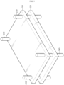
- FIG. 1 is a diagram schematically showing a battery pressure measuring sensor 100 according to an embodiment of the present disclosure.
- the substrate 110 may have a rectangular shape corresponding to the shape of the battery.
- the substrate 110 may be previously divided into a center portion and a peripheral portion in consideration of swelling characteristics of the battery, and the plurality of variable resistor units 120 may be provided in the center portion or the peripheral portion of the substrate 110.
- the battery means one physically separable independent cell provided with a negative electrode terminal and a positive electrode terminal.
- a lithium-ion battery or a lithium polymer battery may be regarded as a battery.
- the battery may be a cylindrical type, a pouch type, or a prismatic type.
- the battery may be a pouch type.
- the plurality of variable resistor units 120 is configured to be provided at a plurality of locations in consideration of a swelling characteristic of the battery.
- the plurality of variable resistor units 120 are configured to be provided at a first location 110a where a preset risk when battery swelling occurs in the substrate 110 is set to be relatively low and at a second location 110b where the preset risk is set be relatively high.
- the first location 110a may be configured as a location corresponding to a preset center portion in the entire portion of the substrate 110.
- the second location 110b may be configured as a location corresponding to a peripheral portion excluding the center portion in the entire portion of the substrate 110. That is, when the substrate 110 and the battery are in contact, the first location 110a of the substrate 110 may correspond to the center portion of the battery. In addition, when the substrate 110 and the battery are in contact, the second location 110b of the substrate 110 may correspond to the peripheral portion in which an electrode lead of the battery may be included.
- some of the plurality of variable resistor units 120 may be attached at the first location 110a corresponding to the center portion of the substrate 110.
- the rest of the plurality of variable resistor units 120 may be attached at the second location 110b corresponding to the peripheral portion of the substrate 110.
- the plurality of variable resistor units 120 are configured such that a resistance value is changed within a corresponding resistance range according to a pressure applied to each unit.
- the plurality of sensing lines 130 are configured to be connected to the plurality of variable resistor units 120, respectively.
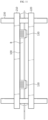
- FIG. 3 is a diagram schematically showing the variable resistor unit 120 and the sensing line 130 included in the battery pressure measuring sensor 100 according to an embodiment of the present disclosure.
- the sensing line 130 may be connected to one end and the other end of the variable resistor unit 120.
- a resistance value of the variable resistor unit 120 may be changed within a resistance range corresponding to the variable resistor unit 120 through current flowing through the variable resistor unit 120 and the sensing line 130.
- variable resistor unit 120 current applied from the sensing line 130 connected to one end of the variable resistor unit 120 may pass through the variable resistor unit 120 and be output to the sensing line 130 connected to the other end of the variable resistor unit 120. Also, when current passes through the variable resistor unit 120, the resistance value of the variable resistor unit 120 may be changed within a corresponding resistance range according to the pressure applied to the variable resistor unit 120.
- the battery pressure measuring sensor 100 measures pressure applied to the substrate 110 through the variable resistor unit 120 and the sensing line 130 attached at various locations of the substrate 110. For example, when pressure is applied to the substrate 110 attached to the battery due to swelling of the battery, the resistance value of the variable resistor unit 120 provided at the location where the pressure is applied may be changed. Therefore, the battery pressure measuring sensor 100 has an advantage of not only being used to judge whether swelling occurs in the battery, but also being usefully used to detect the location where battery swelling occurs.
- the plurality of variable resistor units 120 may be configured such that a resistance value is set to a criterion resistance value when no pressure is applied.
- the resistance value of the plurality of variable resistor units 120 may be a criterion resistance value regardless of a location on the substrate 110.
- the plurality of variable resistor units 120 may be set to have the criterion resistance value that is set to be close to 0 ⁇ when no external pressure is applied.
- the plurality of variable resistor units 120 may have a resistance value of 0 ⁇ when no external pressure is applied.
- the criterion resistance value may be preset to 0 ⁇ .
- the lower limit of the first resistance range is configured to be set to be equal to or greater than the upper limit of the second resistance range. That is, all resistance values belonging to the first resistance range may be greater than or equal to all resistance values belonging to the second resistance range.
- the first resistance range may be 50,000 ⁇ or less and 10,000 ⁇ or more.
- the second resistance range may be 10,000 ⁇ or less and 1,000 ⁇ or more.
- the lower limit (10,000 ⁇ ) of the first resistance range and the upper limit (10,000 ⁇ ) of the second resistance range may be the same. Accordingly, all resistance values belonging to the first resistance range may be greater than or equal to all resistance values belonging to the second resistance range.
- the resistance value of the variable resistor unit 120 may decrease. That is, the strength of the applied pressure and the resistance value of the variable resistor unit 120 may be in inverse proportion to each other.
- the resistance value of the variable resistor unit 120 included in the first location 110a may be greater than the resistance value of the variable resistor unit 120 included in the second location 110b.
- the battery pressure measuring sensor 100 has an advantage of accurately detecting the swelling location of the battery in contact with the substrate 110 by setting the resistance value of the variable resistor unit 120 differently according to the location attached to the substrate 110.
- the resistance value of each of the plurality of variable resistor units 120 may be changed, whether or not swelling occurs in the battery may be judged more accurately.
- the center portion of the battery swells first, and the peripheral portion including electrodes of the battery may swell later than the center portion.
- This phenomenon appears because positive electrode active materials and negative electrode active materials are concentrated more in the center portion of the battery than in the peripheral portion of the battery, so that electrochemical reactions occur more actively.
- an upper case and a lower case of the battery may be sealed at the peripheral portion of the battery, and electrode leads may be connected to the peripheral portion of the battery. Therefore, when swelling occurs in the battery, the center portion of the battery may swell earlier than the peripheral portion of the battery.
- the resistance value of the variable resistor unit 120 provided at the first location 110a of the substrate 110 corresponding to the center portion of the battery is included within the first resistance range, it may be judged that swelling occurs in the battery.
- the upper limit of the first resistance range is a resistance value at which the state of the battery can be judged as a preset swelling generation state. That is, when the resistance value of the variable resistor unit 120 is equal to the upper limit of the first resistance range, the state of the battery may be in a state where the preset risk is low even though swelling occurs. This is because, as described above, the pressure applied to the variable resistor unit 120 and the resistance value of the variable resistor unit 120 are in inverse proportion to each other. That is, when the resistance value of at least one of the plurality of variable resistor units 120 provided at the first location 110a of the substrate 110 is equal to the upper limit of the first resistance range, the state of the battery can be judged as a swelling generation state in which the risk is relatively low.
- the sealed upper and lower cases may be vented so that electrolyte or the like may leak out of the battery.
- the risk when swelling occurs in the battery may be higher than that of the swelling generation state because a fire or explosion may occur in the battery.
- the lower limit of the first resistance range and the upper limit of the second resistance range are resistance values at which the state of the battery can be judged as a preset swelling warning state. That is, when the resistance value of at least one of the plurality of variable resistor units 120 provided at the first location 110a of the substrate 110 is equal to the lower limit of the first resistance range or the resistance value of at least one of the plurality of variable resistor units 120 provided at the second location 110b is equal to the upper limit of the second resistance range, the battery may be in a state where swelling has occurred and the preset risk is middle. That is, the state of the battery can be judged as a swelling warning state where the risk is higher than that of the swelling generation state.
- the lower limit of the second resistance range is a resistance value at which the state of the battery can be judged as a preset swelling dangerous state. That is, when the resistance value of at least one of the plurality of variable resistor units 120 provided at the second location 110b of the substrate 110 is equal to the lower limit of the second resistance range, the battery may be in a state where the risk is highest and there is a very high possibility of fire or explosion. Therefore, the state of the battery can be judged as a swelling dangerous state with the highest risk.
- the battery pressure measuring sensor 100 has an advantage of subdividing and judging the state of the battery according to the swelling risk by setting the resistance range to which the resistance value of the variable resistor unit 120 can belong differently according to the location attached to the substrate 110.
- the state of the battery is divided into a swelling generation state, a swelling warning state and a swelling dangerous state, but it should be noted that the state of the battery can be more diversely classified according to more subdivided risks.
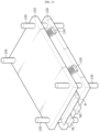
- FIG. 4 is a diagram schematically showing a first embodiment of the battery pressure measuring sensor 100 according to an embodiment of the present disclosure.
- the plurality of sensing lines 130 may be configured so that the wire length of the sensing line 130 connected to the variable resistor unit 120 provided at the first location 110a is longer than the wire length of the sensing line 130 connected to the variable resistor unit 120 provided at the second location 110b.
- variable resistor unit 120 As described with reference to FIG. 3 , current is applied to the variable resistor unit 120 through the sensing line 130 connected to one end of the variable resistor unit 120, and the current passing through the variable resistor unit 120 may be output through the sensing line 130 connected to the other end of the variable resistor unit 120. Therefore, as the sum of the total lengths of the sensing line 130 increases, the resistance value of the variable resistor unit 120 when pressure is applied may increase.
- the wire length of the sensing line 130 connected to the variable resistor unit 120 provided at the first location 110a of the substrate 110 may be longer than the wire length of the sensing line 130 connected to the variable resistor unit 120 provided at the second location 110b of the substrate 110.
- the variable resistor unit 120 provided at the first location 110a of the substrate 110 may respond more sensitively to the applied pressure than the variable resistor unit 120 provided at the second location 110b. That is, even if a small pressure is applied to the variable resistor unit 120 provided at the first location 110a, it may have a high resistance value.
- the substrate 110 may include a plurality of variable resistor units 120a to 120h and a plurality of sensing lines 130a to 130h.
- the first location 110a may include a third variable resistor unit 120, a fourth variable resistor unit 120, a fifth variable resistor unit 120, and a sixth variable resistor unit 120.
- the second location 110b may include a first variable resistor unit 120, a second variable resistor unit 120, a seventh variable resistor unit 120, and an eighth variable resistor unit 120.
- the lengths of the sensing lines 130c, 130d, 130e and 130f connected to the plurality of variable resistor units 120c, 120d, 120e and 120f included in the first location 110a are similar enough to not significantly differ.
- the lengths of the sensing lines 130a, 130b, 130g, and 130h connected to the plurality of variable resistor units 120a, 120b, 120g, and 120h included in the second location 110b are similar enough to not significantly differ.
- the resistance values of the plurality of variable resistor units 120c, 120d, 120e and 120f included in the first location 110a may belong to the first resistance range (for example, 50,000 ⁇ or less and 10,000 ⁇ or more), and the resistance values of the plurality of variable resistor units 120a, 120b, 120g and 120h included in the second location 110b may belong to the second resistance range (for example, less than 10,000 ⁇ and more than 1,000 ⁇ ).
- the state of the battery in contact with the substrate 110 may be judged as a swelling generation state.
- the state of the battery in contact with the substrate 110 may be judged as a swelling warning state.
- the state of the battery in contact with the substrate 110 may be judged as a swelling dangerous state.
- the battery pressure measuring sensor 100 has an advantage of sensitively detecting whether swelling occurs in the battery and specifically detecting the location where battery swelling occurs by differently configuring the wire length of the sensing line 130 connected to the variable resistor unit 120 according to the location of the variable resistor unit 120 attached to the substrate 110.
- FIG. 5 is a diagram schematically showing a second embodiment of the battery pressure measuring sensor 100 according to an embodiment of the present disclosure.
- the plurality of variable resistor units 120 may be configured such that the size of the variable resistor unit 120 provided at the first location 110a is greater than the size of the variable resistor unit 120 provided at the second location 110b.
- variable resistor unit 120 As the size of the variable resistor unit 120 increases, the resistance value of the variable resistor unit 120 when pressure is applied may increase. This is because the variable resistor unit 120 may respond more sensitively to the applied pressure as the size increases. Accordingly, the size of the variable resistor unit 120 included in the first location 110a of the substrate 110 may be greater than the size of the variable resistor unit 120 included in the second location 110b of the substrate 110.
- the size of the plurality of variable resistor units 120c, 120d, 120e and 120f included in the first location 110a may be greater than the size of the plurality of variable resistor units 120a, 120b, 120g and 120h included in the second location 110b. Therefore, the resistance values of the plurality of variable resistor units 120c, 120d, 120e and 120f included in the first location 110a may belong to the first resistance range (for example, 50,000 ⁇ or less and 10,000 ⁇ or more), and the resistance values of the plurality variable resistor units 120a, 120b, 120g and 120h included in the second location 110b may belong to the second resistance range (for example, 10,000 ⁇ or less and 1,000 ⁇ or more).
- the first resistance range for example, 50,000 ⁇ or less and 10,000 ⁇ or more
- the resistance values of the plurality variable resistor units 120a, 120b, 120g and 120h included in the second location 110b may belong to the second resistance range (for example, 10,000 ⁇ or less and 1,000 ⁇ or more).
- the battery pressure measuring sensor 100 has an advantage of sensitively detecting whether swelling occurs in the battery and specifically detecting the location where battery swelling occurs by configuring the size of the variable resistor unit 120 differently according to the location of the variable resistor unit 120 attached to the substrate 110.
- FIG. 6 is a diagram schematically showing a third embodiment of the battery pressure measuring sensor 100 according to an embodiment of the present disclosure.
- the plurality of variable resistor units 120 may be configured such that the number of variable resistor units 120 provided at the first location 110a is less than the number of variable resistor units 120 provided at the second location 110b.
- the second location 110b of the substrate 110 may correspond to the peripheral portion of the battery.
- the peripheral portion of the battery which may include the electrode leads of the battery, is inflated due to swelling, the battery may be vented and there is a risk of fire or explosion. Therefore, it is important to accurately judge whether swelling occurs in the peripheral portion of the battery rather than in the center portion of the battery for accident prevention.
- a plurality of variable resistor units 120c, 120d, 120e and 120f may be included in the first location 110a of the substrate 110, and a plurality of variable resistor units 120a, 120b, 120g, 120h, 120i, 120j, 120k and 120l may be included in the second location 110b of the substrate 110.
- the battery pressure measuring sensor 100 has an advantage of more accurately detecting swelling generated in the peripheral portion of the battery by configuring the number of variable resistor units 120 differently depending on the location of the substrate 110.
- the first embodiment in which the wire length of the sensing line 130 connected to the variable resistor unit 120 is different, the second embodiment in which the size of the variable resistor unit 120 is different, and the third embodiment in which the number of variable resistor units 120 is different have been described.
- the first to third embodiments may be combined with each other in a complementary manner.
- FIG. 7 is a diagram schematically showing a battery pressure measuring apparatus 200 according to another embodiment of the present disclosure.
- a battery pressure measuring apparatus 200 may include a battery pressure measuring sensor 100, an upper plate 210, a lower plate 220, and a fixing unit 230.
- a battery pressure measuring sensor 100 since the battery pressure measuring sensor 100 has been described above, a detailed description thereof will be omitted.
- the battery pressure measuring sensor 100 may be configured to be located on at least one of an upper surface and a lower surface of the battery.
- FIG. 8 is a diagram schematically showing an embodiment in which the battery pressure measuring sensor 100 according to an embodiment of the present disclosure is attached to a battery B.
- the battery B may be a pouch-type battery cell including a positive electrode terminal PE and a negative electrode terminal NE.
- the positive electrode terminal PE and the negative electrode terminal NE are provided together at one end of the battery B, but in another embodiment, the positive electrode terminal PE and the negative electrode terminal NE may be provided at one end and the other end of the battery B, respectively.
- the battery pressure measuring sensor 100 may be attached to the upper surface of the battery B. Specifically, a plurality of variable resistor units 120 and a plurality of sensing lines 130 may be attached to the upper surface of the substrate 110. In addition, the lower surface of the substrate 110 may be attached to the upper surface of the battery B.
- the upper plate 210 and the lower plate 220 may be configured such that the battery B may be interposed therebetween.
- the lower surface of the upper plate 210 and the upper surface of the lower plate 220 may be located to face each other.
- the battery B may be interposed between the upper plate 210 and the lower plate 220. That is, the upper plate 210 may be located on the upper surface of the battery B, and the lower plate 220 may be located on the lower surface of the battery B.
- the fixing unit 230 may be configured to fix the upper plate 210 and the lower plate 220. Specifically, the fixing unit 230 may be configured to pass through the upper plate 210 and the lower plate 220 to fix the upper plate 210 and the lower plate 220. Also, preferably, the upper plate 210 and/or the lower plate 220 may move along the fixing unit 230, so that a distance between the upper plate 210 and the lower plate 220 may be adjusted.
- FIG. 12 is a diagram schematically showing a second embodiment of the battery pressure measuring apparatus 200 according to another embodiment of the present disclosure.
- the battery pressure measuring apparatus 200 may further include a protection plate 240.
- the battery pressure measuring apparatus 200 since the battery pressure measuring apparatus 200 according to an embodiment of the present disclosure further includes the protection plate 240, there is an advantage of preventing damage to the battery B during the battery pressure measurement process.
- the battery pressure measuring apparatus 200 may further include a control unit 250 and a charging and discharging unit 260.
- control unit 250 may be connected to the battery pressure measuring sensor 100.
- control unit 250 may be connected to each sensing line 130 included in the battery pressure measuring sensor 100.
- control unit 250 may judge the swelling state of the battery B using each sensing line 130.
- the charging and discharging unit 260 may be connected to the positive electrode terminal PE and the negative electrode terminal NE of the battery B.
- the battery pressure measuring sensor 100 attached to the battery B and the control unit 250 may be connected.
- the plurality of sensing lines 130 included in the battery pressure measuring sensor 100 and the control unit 250 may be connected.
- the control unit 250 may judge that the state of the battery B is a swelling warning state.
- the control unit 250 may judge that the state of the battery B is a swelling dangerous state.
- the battery pressure measuring apparatus 200 has an advantage of specifically judging the swelling state of the battery B based on the resistance value of the variable resistor units 120 provided at a plurality of locations on the substrate 110.
- control unit 250 may be configured to detect a location where swelling occurs in the battery B based on the plurality of measured resistance values.
- control unit 250 may measure a resistance value of each of the plurality of variable resistor units 120 provided on the substrate 110. Accordingly, the control unit 250 may detect not only the swelling state of the battery B, but also a location where swelling occurs in the battery B.
- the control unit 250 may judge the state of the battery B as a swelling generation state and determine the location where swelling occurs as locations corresponding to the fourth variable resistor unit 120d and the sixth variable resistor unit 120f.
- control unit 250 provided to the battery pressure measuring apparatus 200 may selectively include processors, application-specific integrated circuit (ASIC), other chipsets, logic circuits, registers, communication modems, data processing devices, and the like, known in the art to execute various control logic performed in the present disclosure.
- control logic when the control logic is implemented in software, the control unit 250 may be implemented as a set of program modules.
- the program module may be stored in a memory and executed by the control unit 250.
- the memory may be positioned inside or out of the control unit 250 and may be connected to the control unit 250 by various well-known means.
- the battery pressure measuring sensor 100 according to the present disclosure may be provided in a battery pack. That is, the battery pack according to the present disclosure may include the above-described battery pressure measuring sensor 100, one or more battery cells, and a battery management system (BMS). In addition, the battery pack may further include electrical components (relays, fuses, etc.) and a case.
- BMS battery management system
- the battery pressure measuring sensor 100 may be attached to each battery cell. Also, a plurality of battery cells to which the battery pressure measuring sensor 100 is attached may be included in the battery pack.
- the BMS may be connected to each of the plurality of battery pressure measuring sensors 100 to detect the swelling state and the swelling occurrence location of each of the plurality of battery cells.
Landscapes
- Physics & Mathematics (AREA)
- General Physics & Mathematics (AREA)
- Electrochemistry (AREA)
- Manufacturing & Machinery (AREA)
- Chemical & Material Sciences (AREA)
- Chemical Kinetics & Catalysis (AREA)
- Engineering & Computer Science (AREA)
- General Chemical & Material Sciences (AREA)
- Secondary Cells (AREA)
- Battery Mounting, Suspending (AREA)
- Testing Electric Properties And Detecting Electric Faults (AREA)
- Charge And Discharge Circuits For Batteries Or The Like (AREA)
- Measuring Fluid Pressure (AREA)
Applications Claiming Priority (2)
| Application Number | Priority Date | Filing Date | Title |
|---|---|---|---|
| KR1020210173277A KR20230085008A (ko) | 2021-12-06 | 2021-12-06 | 배터리 압력 측정 센서 및 이를 포함하는 배터리 압력 측정 장치 |
| PCT/KR2022/018131 WO2023106675A1 (ko) | 2021-12-06 | 2022-11-16 | 배터리 압력 측정 센서 및 이를 포함하는 배터리 압력 측정 장치 |
Publications (3)
| Publication Number | Publication Date |
|---|---|
| EP4286816A1 EP4286816A1 (en) | 2023-12-06 |
| EP4286816A4 EP4286816A4 (en) | 2024-09-25 |
| EP4286816B1 true EP4286816B1 (en) | 2025-07-09 |
Family
ID=86730730
Family Applications (1)
| Application Number | Title | Priority Date | Filing Date |
|---|---|---|---|
| EP22904508.3A Active EP4286816B1 (en) | 2021-12-06 | 2022-11-16 | Battery pressure measuring sensor and battery pressure measuring apparatus including the same |
Country Status (9)
| Country | Link |
|---|---|
| US (1) | US20240142322A1 (pl) |
| EP (1) | EP4286816B1 (pl) |
| JP (1) | JP7635947B2 (pl) |
| KR (1) | KR20230085008A (pl) |
| CN (1) | CN116997780A (pl) |
| ES (1) | ES3047361T3 (pl) |
| HU (1) | HUE073005T2 (pl) |
| PL (1) | PL4286816T3 (pl) |
| WO (1) | WO2023106675A1 (pl) |
Families Citing this family (2)
| Publication number | Priority date | Publication date | Assignee | Title |
|---|---|---|---|---|
| KR102862284B1 (ko) * | 2021-11-01 | 2025-09-18 | 주식회사 엘지에너지솔루션 | 배터리 정보 압축 장치 및 방법 |
| KR102703526B1 (ko) * | 2023-11-07 | 2024-09-04 | 부산대학교 산학협력단 | 압력 측정 모듈 및 이를 이용한 압력 분포 측정 장치 |
Family Cites Families (18)
| Publication number | Priority date | Publication date | Assignee | Title |
|---|---|---|---|---|
| JP2014017141A (ja) | 2012-07-10 | 2014-01-30 | Canon Inc | 電子機器 |
| US9806310B1 (en) * | 2014-04-04 | 2017-10-31 | Olaeris, Inc. | Battery failure venting system |
| KR102476001B1 (ko) * | 2015-10-08 | 2022-12-09 | 에스케이온 주식회사 | 배터리 셀 압력 측정 장치 |
| KR20170084789A (ko) * | 2016-01-13 | 2017-07-21 | 주식회사 엘지화학 | 전지셀용 안전부재 및 이를 포함하는 전지팩 |
| US10816416B2 (en) * | 2016-02-06 | 2020-10-27 | Shenzhen New Degree Technology Co., Ltd. | Pressure sensor, electronic device, and method for manufacturing pressure sensor |
| CN106816929A (zh) * | 2017-02-16 | 2017-06-09 | 上海与德通讯技术有限公司 | 电池、终端及电池保护方法 |
| KR102367352B1 (ko) * | 2017-03-31 | 2022-02-25 | 삼성전자주식회사 | 배터리 장치, 배터리 모니터링 장치 및 방법 |
| WO2019146960A1 (ko) * | 2018-01-24 | 2019-08-01 | 주식회사 아모그린텍 | 배터리 압력 감지 센서 및 이를 구비한 단말기 |
| KR102447552B1 (ko) * | 2018-03-09 | 2022-09-23 | 주식회사 엘지에너지솔루션 | 이차 전지 상태 검출 장치 |
| JP6839127B2 (ja) | 2018-04-16 | 2021-03-03 | 日本メクトロン株式会社 | 圧力センサ、圧力センサの製造方法 |
| JP7008618B2 (ja) * | 2018-08-28 | 2022-01-25 | ミネベアミツミ株式会社 | 電池パック |
| US12159983B2 (en) * | 2018-09-04 | 2024-12-03 | Hutchinson Technology Incorporated | Sensored battery pouch |
| KR102152572B1 (ko) * | 2019-03-22 | 2020-09-07 | 영남대학교 산학협력단 | 이차 전지의 팽창 센싱 시스템 |
| JP2021034219A (ja) | 2019-08-23 | 2021-03-01 | 株式会社ケーヒン | 電池モジュール |
| KR102242968B1 (ko) * | 2019-09-19 | 2021-04-21 | 주식회사 아이디피 | 배터리의 이상징후 또는 열화 모니터링을 위한 시스템 |
| KR102782961B1 (ko) * | 2020-03-20 | 2025-03-14 | 주식회사 엘지에너지솔루션 | 배터리 스웰링 검사 장치 |
| DE102023104018A1 (de) * | 2023-02-17 | 2024-08-22 | Man Truck & Bus Se | Speicher für elektrische Energie mit mindestens einer Batteriezelle und einem Sensor zur Erfassung des Zell-Swellings, sowie Verfahren zur Herstellung des Speichers für elektrische Energie |
| KR102703791B1 (ko) * | 2023-06-14 | 2024-09-06 | 주식회사 폴리웍스 | 압력센서와 온도센서가 결합된 필름형 복합센서 |
-
2021
- 2021-12-06 KR KR1020210173277A patent/KR20230085008A/ko active Pending
-
2022
- 2022-11-16 EP EP22904508.3A patent/EP4286816B1/en active Active
- 2022-11-16 PL PL22904508.3T patent/PL4286816T3/pl unknown
- 2022-11-16 JP JP2023551782A patent/JP7635947B2/ja active Active
- 2022-11-16 US US18/279,146 patent/US20240142322A1/en active Pending
- 2022-11-16 CN CN202280021510.XA patent/CN116997780A/zh active Pending
- 2022-11-16 HU HUE22904508A patent/HUE073005T2/hu unknown
- 2022-11-16 WO PCT/KR2022/018131 patent/WO2023106675A1/ko not_active Ceased
- 2022-11-16 ES ES22904508T patent/ES3047361T3/es active Active
Also Published As
| Publication number | Publication date |
|---|---|
| WO2023106675A1 (ko) | 2023-06-15 |
| JP7635947B2 (ja) | 2025-02-26 |
| CN116997780A (zh) | 2023-11-03 |
| JP2024513152A (ja) | 2024-03-22 |
| EP4286816A1 (en) | 2023-12-06 |
| US20240142322A1 (en) | 2024-05-02 |
| PL4286816T3 (pl) | 2025-10-06 |
| HUE073005T2 (hu) | 2025-12-28 |
| ES3047361T3 (en) | 2025-12-03 |
| KR20230085008A (ko) | 2023-06-13 |
| EP4286816A4 (en) | 2024-09-25 |
Similar Documents
| Publication | Publication Date | Title |
|---|---|---|
| US11802918B2 (en) | Thermal runaway detecting device, battery system, and thermal runaway detecting method of battery system | |
| US20230179007A1 (en) | Battery Management Apparatus and Method | |
| US20240044995A1 (en) | Battery Management Apparatus and Method | |
| US9653724B2 (en) | Secondary battery, and secondary battery module and secondary battery pack comprising the same | |
| EP3840083B1 (en) | Thermal runaway detection system and battery system | |
| KR20130123098A (ko) | 배터리 밸런싱 시스템 및 이를 이용한 배터리 밸런싱 방법 | |
| US20190379092A1 (en) | Method and system for validating a temperature sensor in a battery cell | |
| EP4286816B1 (en) | Battery pressure measuring sensor and battery pressure measuring apparatus including the same | |
| JP2023503584A (ja) | スウェリング測定正確度が向上したバッテリーパック | |
| EP3579006B1 (en) | Validation of a temperature sensor of a battery cell | |
| KR102473230B1 (ko) | 배터리 관리 장치 및 방법 | |
| KR20220018832A (ko) | 전기 차량용 배터리의 열폭주 감지 장치 | |
| EP3043441B1 (en) | Battery management unit for preventing performance of erroneous control algorithm from communication error | |
| US20260043870A1 (en) | Abnormal cell detection method, abnormal cell detection device, and battery pack | |
| US20160141729A1 (en) | Protection apparatus for rechargeable battery and protection method for rechargeable battery using the same | |
| US20260100431A1 (en) | Systems and methods for detecting thermal runaway | |
| EP4468003B1 (en) | Apparatus and method for diagnosing battery | |
| KR102954301B1 (ko) | 열 폭주 감지용 압력 센서를 구비한 배터리 모듈 | |
| US20240014494A1 (en) | Battery module having pressure sensor for detecting thermal propagation | |
| KR20250001866A (ko) | 전지 모듈 | |
| KR20250049131A (ko) | 전지 모듈 | |
| KR20250162217A (ko) | 배터리 진단 방법 및 장치 |
Legal Events
| Date | Code | Title | Description |
|---|---|---|---|
| STAA | Information on the status of an ep patent application or granted ep patent |
Free format text: STATUS: THE INTERNATIONAL PUBLICATION HAS BEEN MADE |
|
| PUAI | Public reference made under article 153(3) epc to a published international application that has entered the european phase |
Free format text: ORIGINAL CODE: 0009012 |
|
| STAA | Information on the status of an ep patent application or granted ep patent |
Free format text: STATUS: REQUEST FOR EXAMINATION WAS MADE |
|
| 17P | Request for examination filed |
Effective date: 20230830 |
|
| AK | Designated contracting states |
Kind code of ref document: A1 Designated state(s): AL AT BE BG CH CY CZ DE DK EE ES FI FR GB GR HR HU IE IS IT LI LT LU LV MC ME MK MT NL NO PL PT RO RS SE SI SK SM TR |
|
| REG | Reference to a national code |
Ref country code: DE Free format text: PREVIOUS MAIN CLASS: G01L0019060000 Ipc: G01L0001200000 Ref country code: DE Ref legal event code: R079 Ref document number: 602022017484 Country of ref document: DE Free format text: PREVIOUS MAIN CLASS: G01L0019060000 Ipc: G01L0001200000 |
|
| A4 | Supplementary search report drawn up and despatched |
Effective date: 20240822 |
|
| RIC1 | Information provided on ipc code assigned before grant |
Ipc: G01B 7/16 20060101ALI20240817BHEP Ipc: H01M 10/48 20060101ALI20240817BHEP Ipc: H01M 10/42 20060101ALI20240817BHEP Ipc: G01L 1/20 20060101AFI20240817BHEP |
|
| DAV | Request for validation of the european patent (deleted) | ||
| DAX | Request for extension of the european patent (deleted) | ||
| GRAP | Despatch of communication of intention to grant a patent |
Free format text: ORIGINAL CODE: EPIDOSNIGR1 |
|
| STAA | Information on the status of an ep patent application or granted ep patent |
Free format text: STATUS: GRANT OF PATENT IS INTENDED |
|
| INTG | Intention to grant announced |
Effective date: 20250424 |
|
| GRAS | Grant fee paid |
Free format text: ORIGINAL CODE: EPIDOSNIGR3 |
|
| GRAA | (expected) grant |
Free format text: ORIGINAL CODE: 0009210 |
|
| STAA | Information on the status of an ep patent application or granted ep patent |
Free format text: STATUS: THE PATENT HAS BEEN GRANTED |
|
| P01 | Opt-out of the competence of the unified patent court (upc) registered |
Free format text: CASE NUMBER: APP_22951/2025 Effective date: 20250514 |
|
| AK | Designated contracting states |
Kind code of ref document: B1 Designated state(s): AL AT BE BG CH CY CZ DE DK EE ES FI FR GB GR HR HU IE IS IT LI LT LU LV MC ME MK MT NL NO PL PT RO RS SE SI SK SM TR |
|
| REG | Reference to a national code |
Ref country code: GB Ref legal event code: FG4D |
|
| REG | Reference to a national code |
Ref country code: CH Ref legal event code: EP |
|
| REG | Reference to a national code |
Ref country code: IE Ref legal event code: FG4D |
|
| REG | Reference to a national code |
Ref country code: DE Ref legal event code: R096 Ref document number: 602022017484 Country of ref document: DE |
|
| REG | Reference to a national code |
Ref country code: SE Ref legal event code: TRGR |
|
| REG | Reference to a national code |
Ref country code: NL Ref legal event code: MP Effective date: 20250709 |
|
| REG | Reference to a national code |
Ref country code: ES Ref legal event code: FG2A Ref document number: 3047361 Country of ref document: ES Kind code of ref document: T3 Effective date: 20251203 |
|
| PG25 | Lapsed in a contracting state [announced via postgrant information from national office to epo] |
Ref country code: PT Free format text: LAPSE BECAUSE OF FAILURE TO SUBMIT A TRANSLATION OF THE DESCRIPTION OR TO PAY THE FEE WITHIN THE PRESCRIBED TIME-LIMIT Effective date: 20251110 |
|
| PGFP | Annual fee paid to national office [announced via postgrant information from national office to epo] |
Ref country code: HU Payment date: 20251127 Year of fee payment: 4 |
|
| PG25 | Lapsed in a contracting state [announced via postgrant information from national office to epo] |
Ref country code: NL Free format text: LAPSE BECAUSE OF FAILURE TO SUBMIT A TRANSLATION OF THE DESCRIPTION OR TO PAY THE FEE WITHIN THE PRESCRIBED TIME-LIMIT Effective date: 20250709 |
|
| REG | Reference to a national code |
Ref country code: AT Ref legal event code: MK05 Ref document number: 1812189 Country of ref document: AT Kind code of ref document: T Effective date: 20250709 |
|
| REG | Reference to a national code |
Ref country code: HU Ref legal event code: AG4A Ref document number: E073005 Country of ref document: HU |
|
| PG25 | Lapsed in a contracting state [announced via postgrant information from national office to epo] |
Ref country code: IS Free format text: LAPSE BECAUSE OF FAILURE TO SUBMIT A TRANSLATION OF THE DESCRIPTION OR TO PAY THE FEE WITHIN THE PRESCRIBED TIME-LIMIT Effective date: 20251109 |
|
| PGFP | Annual fee paid to national office [announced via postgrant information from national office to epo] |
Ref country code: DE Payment date: 20251020 Year of fee payment: 4 |
|
| PG25 | Lapsed in a contracting state [announced via postgrant information from national office to epo] |
Ref country code: NO Free format text: LAPSE BECAUSE OF FAILURE TO SUBMIT A TRANSLATION OF THE DESCRIPTION OR TO PAY THE FEE WITHIN THE PRESCRIBED TIME-LIMIT Effective date: 20251009 |
|
| REG | Reference to a national code |
Ref country code: LT Ref legal event code: MG9D |
|
| PG25 | Lapsed in a contracting state [announced via postgrant information from national office to epo] |
Ref country code: AT Free format text: LAPSE BECAUSE OF FAILURE TO SUBMIT A TRANSLATION OF THE DESCRIPTION OR TO PAY THE FEE WITHIN THE PRESCRIBED TIME-LIMIT Effective date: 20250709 |
|
| PG25 | Lapsed in a contracting state [announced via postgrant information from national office to epo] |
Ref country code: FI Free format text: LAPSE BECAUSE OF FAILURE TO SUBMIT A TRANSLATION OF THE DESCRIPTION OR TO PAY THE FEE WITHIN THE PRESCRIBED TIME-LIMIT Effective date: 20250709 |
|
| PG25 | Lapsed in a contracting state [announced via postgrant information from national office to epo] |
Ref country code: HR Free format text: LAPSE BECAUSE OF FAILURE TO SUBMIT A TRANSLATION OF THE DESCRIPTION OR TO PAY THE FEE WITHIN THE PRESCRIBED TIME-LIMIT Effective date: 20250709 |
|
| PGFP | Annual fee paid to national office [announced via postgrant information from national office to epo] |
Ref country code: FR Payment date: 20251021 Year of fee payment: 4 |
|
| PG25 | Lapsed in a contracting state [announced via postgrant information from national office to epo] |
Ref country code: GR Free format text: LAPSE BECAUSE OF FAILURE TO SUBMIT A TRANSLATION OF THE DESCRIPTION OR TO PAY THE FEE WITHIN THE PRESCRIBED TIME-LIMIT Effective date: 20251010 |
|
| PGFP | Annual fee paid to national office [announced via postgrant information from national office to epo] |
Ref country code: BE Payment date: 20251020 Year of fee payment: 4 |
|
| PGFP | Annual fee paid to national office [announced via postgrant information from national office to epo] |
Ref country code: SE Payment date: 20251021 Year of fee payment: 4 |
|
| PG25 | Lapsed in a contracting state [announced via postgrant information from national office to epo] |
Ref country code: LV Free format text: LAPSE BECAUSE OF FAILURE TO SUBMIT A TRANSLATION OF THE DESCRIPTION OR TO PAY THE FEE WITHIN THE PRESCRIBED TIME-LIMIT Effective date: 20250709 |
|
| PG25 | Lapsed in a contracting state [announced via postgrant information from national office to epo] |
Ref country code: BG Free format text: LAPSE BECAUSE OF FAILURE TO SUBMIT A TRANSLATION OF THE DESCRIPTION OR TO PAY THE FEE WITHIN THE PRESCRIBED TIME-LIMIT Effective date: 20250709 |
|
| PGFP | Annual fee paid to national office [announced via postgrant information from national office to epo] |
Ref country code: PL Payment date: 20251021 Year of fee payment: 4 |
|
| PG25 | Lapsed in a contracting state [announced via postgrant information from national office to epo] |
Ref country code: RS Free format text: LAPSE BECAUSE OF FAILURE TO SUBMIT A TRANSLATION OF THE DESCRIPTION OR TO PAY THE FEE WITHIN THE PRESCRIBED TIME-LIMIT Effective date: 20251009 |
|
| PGFP | Annual fee paid to national office [announced via postgrant information from national office to epo] |
Ref country code: ES Payment date: 20251215 Year of fee payment: 4 |
|
| PG25 | Lapsed in a contracting state [announced via postgrant information from national office to epo] |
Ref country code: RO Free format text: LAPSE BECAUSE OF FAILURE TO SUBMIT A TRANSLATION OF THE DESCRIPTION OR TO PAY THE FEE WITHIN THE PRESCRIBED TIME-LIMIT Effective date: 20250709 |
|
| PG25 | Lapsed in a contracting state [announced via postgrant information from national office to epo] |
Ref country code: SM Free format text: LAPSE BECAUSE OF FAILURE TO SUBMIT A TRANSLATION OF THE DESCRIPTION OR TO PAY THE FEE WITHIN THE PRESCRIBED TIME-LIMIT Effective date: 20250709 |
|
| PG25 | Lapsed in a contracting state [announced via postgrant information from national office to epo] |
Ref country code: DK Free format text: LAPSE BECAUSE OF FAILURE TO SUBMIT A TRANSLATION OF THE DESCRIPTION OR TO PAY THE FEE WITHIN THE PRESCRIBED TIME-LIMIT Effective date: 20250709 |
|
| PG25 | Lapsed in a contracting state [announced via postgrant information from national office to epo] |
Ref country code: IT Free format text: LAPSE BECAUSE OF FAILURE TO SUBMIT A TRANSLATION OF THE DESCRIPTION OR TO PAY THE FEE WITHIN THE PRESCRIBED TIME-LIMIT Effective date: 20250709 |