EP4286804A1 - Ladenwaage - Google Patents
Ladenwaage Download PDFInfo
- Publication number
- EP4286804A1 EP4286804A1 EP22176873.2A EP22176873A EP4286804A1 EP 4286804 A1 EP4286804 A1 EP 4286804A1 EP 22176873 A EP22176873 A EP 22176873A EP 4286804 A1 EP4286804 A1 EP 4286804A1
- Authority
- EP
- European Patent Office
- Prior art keywords
- scales
- housing
- removable cover
- load
- weighing
- Prior art date
- Legal status (The legal status is an assumption and is not a legal conclusion. Google has not performed a legal analysis and makes no representation as to the accuracy of the status listed.)
- Granted
Links
Images


Classifications
-
- G—PHYSICS
- G01—MEASURING; TESTING
- G01G—WEIGHING
- G01G23/00—Auxiliary devices for weighing apparatus
- G01G23/01—Testing or calibrating of weighing apparatus
- G01G23/017—Securing calibration against fraud
-
- G—PHYSICS
- G01—MEASURING; TESTING
- G01G—WEIGHING
- G01G21/00—Details of weighing apparatus
- G01G21/28—Frames, Housings
-
- G—PHYSICS
- G01—MEASURING; TESTING
- G01G—WEIGHING
- G01G3/00—Weighing apparatus characterised by the use of elastically-deformable members, e.g. spring balances
- G01G3/12—Weighing apparatus characterised by the use of elastically-deformable members, e.g. spring balances wherein the weighing element is in the form of a solid body stressed by pressure or tension during weighing
- G01G3/14—Weighing apparatus characterised by the use of elastically-deformable members, e.g. spring balances wherein the weighing element is in the form of a solid body stressed by pressure or tension during weighing measuring variations of electrical resistance
-
- G—PHYSICS
- G01—MEASURING; TESTING
- G01V—GEOPHYSICS; GRAVITATIONAL MEASUREMENTS; DETECTING MASSES OR OBJECTS; TAGS
- G01V8/00—Prospecting or detecting by optical means
- G01V8/10—Detecting, e.g. by using light barriers
- G01V8/12—Detecting, e.g. by using light barriers using one transmitter and one receiver
-
- G—PHYSICS
- G01—MEASURING; TESTING
- G01G—WEIGHING
- G01G19/00—Weighing apparatus or methods adapted for special purposes not provided for in the preceding groups
- G01G19/40—Weighing apparatus or methods adapted for special purposes not provided for in the preceding groups with provisions for indicating, recording, or computing price or other quantities dependent on the weight
- G01G19/413—Weighing apparatus or methods adapted for special purposes not provided for in the preceding groups with provisions for indicating, recording, or computing price or other quantities dependent on the weight using electromechanical or electronic computing means
- G01G19/414—Weighing apparatus or methods adapted for special purposes not provided for in the preceding groups with provisions for indicating, recording, or computing price or other quantities dependent on the weight using electromechanical or electronic computing means using electronic computing means only
- G01G19/4144—Weighing apparatus or methods adapted for special purposes not provided for in the preceding groups with provisions for indicating, recording, or computing price or other quantities dependent on the weight using electromechanical or electronic computing means using electronic computing means only for controlling weight of goods in commercial establishments, e.g. supermarket, P.O.S. systems
Definitions
- the present invention relates to a scale, in particular a shop scale, with a weighing module.
- the weighing module includes a housing in which a load cell is housed.
- the load cell includes a fixed section, a deformation section and a movable section.
- the fixed section is connected to the housing and the movable section carries a load cross with a load plate.
- the deformation section has a strain gauge for measuring a weight acting on the load plate.
- a load cell with a fuse for the calibration-relevant electronics is, for example, from the EP3370044B1 known.
- the object of the invention is to create a shop scale in which it can be easily checked that no calibration-relevant changes have been made to the scale.
- the weighing module includes a housing in which a load cell is housed.
- the load cell includes a fixed section, a deformation section and a movable section.
- the fixed section is connected to the housing.
- the fixed section is screwed to the housing.
- the fixed section is screwed to the housing with two or four screws.
- the movable section carries a load cross.
- the housing is open at the top in the area of the load cell.
- the load cross carries a load plate. The housing is closed by the load plate and by the edges of the load plate projecting downward over the upper edge of the housing.
- the deformation section of the load cell has at least one strain gauge for measuring a weight acting on the load plate.
- a circuit board with electronics for processing the signal from the at least one strain gauge is attached to the fixed section of the load cell.
- the electronics include a memory in which calibration-relevant data, in particular calibration data, of the load cell and/or a value for the gravitational acceleration are stored. This is data that must be secured against manipulation in accordance with the Calibration Act. When changing this data, the calibration mark must be destroyed to make the change visible. In other words, according to the calibration law, this data cannot be changed without necessarily destroying the calibration mark.
- the scale includes a first removable cover secured to the fixed portion of the load cell by means of a first fastener.
- the first fastening element is a first fastening screw.
- the first fastening element, in particular the first fastening screw, is secured by a calibration mark.
- the first removable cover protects the circuit board memory against manipulation of calibration-relevant data.
- the first covers Removable cover provides a hardware interface that is suitable for changing the calibration-relevant data.
- the load cell is attached with its fixed section to the housing of the weighing module with at least a second fastening element. In one embodiment, the load cell is fastened with its fixed section to the housing of the weighing module with at least a second fastening screw. In one embodiment, the fixed section of the load cell is attached to the housing of the weighing module using two second fastening screws. In one embodiment, the load cell is fastened with its fixed section to the housing of the weighing module with four second fastening screws.
- the at least one second fastening element, in particular the at least one second fastening screw, is covered by a second removable cover.
- the at least one second fastening element in particular the at least one second fastening screw, is accessible and detachable from outside the housing if the second removable cover is removed.
- the at least one second fastening element on the outside of the housing of the weighing module is accessible and can be released. If the at least one second fastening element is at least a second fastening screw, the screw head(s) can be accessed and detached from the outside of the housing of the weighing module after the second cover has been removed.
- the second removable cover is attached to the housing of the weigh module or to the fixed portion of the load cell by a third fastener within the housing.
- the third fastener is a third fastening screw.
- the first removable cover covers the third fastening element, in particular the third fastening screw, such that the third Fastening element, in particular the third fastening screw, cannot be loosened if the first removable cover is not removed. This means that only after the first removable cover has been removed can the third fastening element be released.
- the at least one second fastening element in particular the at least one second fastening screw, is mounted in a recess on an underside of the housing of the weighing module and penetrates the housing of the weighing module through a through opening.
- the second removable cover is mounted in the recess when secured to the housing of the weigh module or to the fixed portion of the load cell by the third fastener.
- the second removable cover consists of a flat plate to which an elongated, in particular a cylindrical, holding element is attached.
- the elongated, in particular the cylindrical, holding element of the second removable cover is mounted in a tubular opening in the housing of the weighing module in an assembled state.
- the elongated, in particular the cylindrical, holding element is fixed to the tubular opening with the third fastening screw.
- the third fastening screw is screwed longitudinally into the cylindrical retaining member of the second removable cover. This means that the axis of the third fastening screw and the axis of the cylindrical holding element run parallel and in particular coincide.
- the screw head of the third fastening screw has a diameter that is larger than the diameter of the tubular opening of the housing of the weighing module. The screw head prevents the cylindrical holding element from being pulled out of the tubular opening.
- the fixed section has a recess on the top side into which the circuit board is inserted horizontally.
- the recess is open towards the end of the fixed section, that is, towards the force-receiving end of the load cell.
- the first removable cover is placed from above onto the recess of the fixed section and at least partially covers the recess and the circuit board.
- the first removable cover covers the recess and the circuit board in such a way that the electronics for processing the signal from the at least one strain gauge and/or the memory with the calibration-relevant data and possibly a hardware interface for accessing the memory can only be used after removal accessible from the first removable cover.
- the first removable cover is designed as a plate-shaped structure that is at least partially supported on the fixed section of the weighing cell.
- the first removable cover has an extension which covers the top of the third fastening element, in particular the screw head of the third fastening screw.
- the screw head of the third fastening screw is arranged next to the fixed section of the load cell, so that the extension protrudes beyond the base body of the first removable cover and in particular the extension is offset in height from the plate-shaped structure by a Z-shaped design and in height near the top the screw head of the third fastening screw is arranged.
- the at least one second fastening element in particular the at least one second fastening screw, is not secured by a separate calibration mark.
- the third fastening element, in particular the third fastening screw is not secured by a separate calibration mark.
- a hardware interface is provided on the circuit board, via which the memory can be accessed and via which the calibration data stored in the memory and/or the value for the gravitational acceleration can be changed.
- Electronic write protection is provided for the memory.
- the electronics include a switching device to deactivate the write protection of the memory. The switching device can only be operated after removing the first fastening element, in particular the first fastening screw, and/or after removing the first removable cover. This way write protection can be deactivated.
- the switching device is a sensor which is designed to detect a removal of the first fastening element from its fastened position, in particular a unscrewing of the first fastening screw, and to output a switching signal after detecting a removal of the first fastening element to deactivate the write protection of the memory.
- the calibration mark is necessarily violated when the first fastening element is removed. That is, removing the first fastener allows write access to the memory by disabling the memory's write protection. This means that the device is no longer calibrated, as it can no longer be traced whether the data in the memory has been changed or not and whether the load cell still meets the requirements of the calibration law due to changes.
- the device Due to the mandatory violation of the calibration mark when the first fastener is removed, which is necessary to deactivate the write protection of the memory, it can be seen that the device is in an uncalibrated state. In one embodiment, it is imperative to remove the first fastener to output a switching signal to deactivate the write protection of the memory.
- the senor is a light barrier with a transmitter and a receiver, which is arranged such that the beam path between the transmitter and the receiver is interrupted when the first fastening element is in its fastened position, and which is designed to do so Output a switching signal to deactivate the write protection of the memory when the beam path between the transmitter and the receiver is no longer interrupted by the first fastening element.
- the load cross has a recess through which the calibration mark is visible after opening the housing of the weighing module by removing the load plate from the load cross.
- the calibration mark and the first fastening element are accessible and removable through the recess in the load cross.
- the first fastening element can be removed through the recess in the load cross after removing the calibration mark, without the first removable cover being able to be removed through the recess in the load cross. This still has the advantage that write access to the memory is enabled and this is documented by the violation of the calibration mark.
- Fig. 1 shows a shop scale 1 according to the invention.
- the shop scale 1 includes a weighing module 10.
- the weighing module 10 includes a housing 11, which is made, for example, from a cast alloy.
- a load cell is housed in the housing 11 and carries a load plate 12 via a load cross.
- the load plate 12 consists of a sheet metal part with downwardly projecting edges 15 which protrude over the upper edge of the housing 11.
- the housing 11 of the weighing module 10 which is open at the top, is closed by the load plate 12 placed on the load cross.
- the load plate 12 protects the interior of the housing of the weighing module 10 and the load cell located therein from dirt and environmental influences.
- the weight of an object placed on the load plate 12 is determined via the load cell.
- the weighing module 10 is supported on a table top or counter via adjustable feet 13.
- a tripod 5 is attached to the weighing module 10 via a holder 14.
- the tripod carries an operator display 2 facing an operator, which is designed as a touchscreen and allows the operator to interact with the shop scales 1.
- the tripod carries a customer display 3, which faces a customer during sales and shows him various information, such as the weight or price of a product on display, the name of the product and other additional information or advertising information.
- the customer display 3 is also designed as a touchscreen, so that the customer can also interact with the shop scales 1, for example, can log in with a customer account in order to collect points for their current purchase.
- a CPU unit 4 which includes the electronics for data processing and for controlling the printer 6.
- the housing 11 of the weighing module 10 there is a power supply that ensures the power supply for the printer 6 and CPU unit 4 as well as the displays 2, 3.
- the electrical connections between the individual components, such as the power supply, printer 6, CPU unit 4 and the displays 2, 3, take place via cable connections, with the cables being guided from the housing 11 of the weighing module 10 via the holder 14 into the stand 5.
- the cables run within the holder 14 and within the tripod 5 and via openings on the tripod directly into openings in the printer 6 and the CPU unit 4, so that the cables are not visible from the outside. The cables therefore do not disturb the appearance of the shop scales 1.
- the cables are designed as standard cables, preferably USB-C cables, so that inexpensive modules that are available on the market can be used when manufacturing the shop scales 1.
- the customer display 3 and the operator display 2 the power supply and other components to be standard modules available on the market that are connected to each other via USB-C cables.
- the load cell and its electronics, the electronics in the CPU unit 4 and the printer 6 are modules specially developed and adapted for the scale. With this combination of standard modules 2, 3, if available, and individual modules 4, 6, the production of a cost-effective shop scale 1 is possible. Great flexibility and modularity is also possible, for example by replacing the operator display 2 or the customer display 3 with other display sizes. All modules preferably support plug-and-play functions via the USB-C interfaces.
- the person skilled in the art understands that the USB-C interface is mentioned as an example, but that any other currently or future available universal interface is possible for establishing standardized cable connections between the individual modules.
- Fig. 2 shows the weighing module 10 with the load plate 12 removed in an isometric view.
- the housing 11 of the weighing module is open at the top, with the load cross 16 being screwed onto the movable section of the weighing cell via a fastening device 18.
- the load cell in the open area of the housing 11 is covered by the load cross 16 in this view.
- the load cross 16 is kept floating over the movable section of the weighing cell and movable in the direction of the housing 11.
- the load cross 16 moves in the direction of the housing 11 of the weighing module 10 when a weight force is applied to the load cross 16 and leads to a deformation of the deformation section of the load cell.
- the load cross 16 must not touch the housing 11 of the weighing module 10 at any point so that no force shunt occurs between the movable section and the fixed section of the weighing cell. This would distort the weighing result.
- the load cross 16 includes six receiving points 17 which carry the load plate 12.
- the receiving points 17 are formed from rubber recesses in which the load plate 12 can be attached to the receiving points 17 with precisely fitting metal bolts attached to the underside, so that the load plate 12 has a stable hold on the load cross 16 when the housing 11 is pushed through the load plate 12 closed is.
- the load plate 12 can be removed from the load cross 16 by moving upwards in order to open the weighing module 10.
- the load cross 16 includes a recess 19 in the area of the fixed section of the load cell, through which the load cell underneath can be viewed.
- a circuit board with electronics for processing the signal from at least one strain gauge of the weighing cell.
- This electronics is covered by a first removable cover 20.
- the first removable cover is attached to the fixed portion of the load cell by a first fastener.
- the first fastening element of the first removable cover 20 is protected by a calibration mark 21, which passes through the recess 19 in the load cross 16 after opening the housing 11 of the Weighing module 10 is visible by removing the load plate 12 from the load cross 16.
- Fig. 3 and Fig. 4 show the weighing module 10 in a view from above.
- the load cross is not shown.
- the load cross is screwed with screws 31 via the fastening device 18, so that it is not intended that the load cross 16 as in Fig. 3 and Fig. 4 shown is removed.
- the load cell 30 is shown in an open area 112 of the housing 11 of the weighing module 10, which includes screws 31 on its movable section for receiving the load cross.
- the weight to be weighed is introduced into the weighing cell 30 at this movable section.
- the load cell 30 includes a deformation section on which at least one strain gauge 32 is attached.
- the load cell 30 is screwed with its fixed section to the housing 11 of the weighing module 10.
- a circuit board 33 is mounted in a recess on the fixed section.
- the circuit board 33 includes electronics for processing the signal from the at least one strain gauge.
- the electronics include a memory in which calibration-relevant data, in particular calibration data of the weighing cell, and/or a value for the gravitational acceleration are stored.
- the circuit board 33 is as in Fig. 3 shown covered by a first removable cover 20.
- the first removable cover 20 is attached to the fixed portion of the load cell 30 by a first fixing screw.
- the first fastening screw is covered by a calibration mark 21.
- the first removable cover 20 has an extension 22 which covers a screw head of a third fastening screw on the top side.
- the housing 11 includes a separate installation space, which is arranged in a U-shape around the load cell 30, in which various modules, such as a power supply and connecting cables, are accommodated.
- This installation space is covered by a cover plate 111, even if the weighing module 10 is open at the top due to the removed load plate 12.
- the cover plate 111 does not cover the open area 112 of the housing in which the weighing cell 30 is located.
- the cover plate 111 does not close the housing 11 of the weighing module 10.
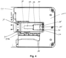
- Fig. 4 shows the weighing module 10 with the first removable cover removed.
- the circuit board 33 is completely visible in this view.
- the circuit board is screwed to the fixed section of the load cell 30 with two screws 34.
- the circuit board 33 is contacted with a USB plug 38 with a cable and passes on the weighing results to the CPU unit 4 of the shop scales 1 via the cable.
- the circuit board 33 has a hole 35 through which the first fastening screw protrudes when the first removable cover 20 is fastened to the fixed part of the load cell with the first fastening screw.
- the circuit board 33 has at least one hardware interface electrically connected to the electronics at its longitudinal end, which is located at the end of the fixed section of the load cell 30.
- the weighing cell 30 can be adjusted during the manufacture of the load cell 30 or during a calibration process by a calibration official.
- calibration data of the weighing cell 30 is stored in a calibratable memory of the electronics, with an electronic write protection then being activated in order to prevent subsequent unauthorized manipulation of the calibration data.
- This hardware interface is covered by the first removable cover.
- the presence of the first fastening screw 40 can be from a cover attached to the underside of the circuit board 32 and inaccessible from the outside by the first removable cover 20 covered light barrier can be detected.
- the transmitter and the receiver of the light barrier are arranged on two opposite sides of the hole 35 formed in the circuit board 33, so that the light barrier is interrupted by the screwed-in first fastening screw 40.
- the light barrier is designed in such a way that a switching signal is generated when the light barrier is no longer interrupted by the fastening screw 40, ie when the fastening screw 40 is unscrewed.
- the switching signal of the light barrier is used to cancel the above-explained electronic write protection of the memory with the calibration data of the weighing cell 30, as is required for a permissible recalibration of the weighing cell 30.
- Fig. 4 shows the screw head of the third fastening screw 37 next to the fixed section of the load cell 30.
- the third fastening screw 37 is fastened in a holding element of a second removable cover, the holding element of the second removable cover being located in a tubular opening of the housing 11 of the weighing module 10 and through the third fastening screw 37 is fixed at the upper end 36 of the tubular opening 46.
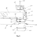
- Fig. 5 shows an exploded view of a sectional drawing through the weighing module 10. It shows how the weighing cell 30 with its fixed section is screwed from below to the housing 11 of the weighing module with two screws 45.
- the screws 45 run from below, from outside the housing 11, through an opening in the housing 11, inwards and are screwed into the fixed section of the weighing cell 30.
- the screw heads of the screws 45 are accessible outside the housing 11.
- a recess 44 is provided in the area of the screws 45 on the housing, into which a second removable cover 42 can be inserted.
- the second removable cover 42 is fastened in the recess 44 with a latching mechanism 47, 48.
- the second removable cover 42 consists of a flat plate and a cylindrical holding element 43, which is mounted in a tubular opening 46 in the housing 11 of the weighing module 10 in the assembled state. At the inner end 36 of the tubular opening 46, the end of the cylindrical holding element 43 is flush with the tubular opening when the second removable cover 42 is attached in the recess 44.
- a third fastening screw 41 is screwed into the cylindrical holding element 43 from above and longitudinally. The screw head of the third fastening screw 41 rests against the inner end 36 of the tubular opening and secures the second removable cover 42 in the intended position.
- the screws 45 which hold the fixed section of the load cell 30 to the housing 11, can only be unscrewed when the third fastening screw 41 inside the housing 11 is removed.
- the extension 22 of the first removable cover 20 covers the screw head of the third fixing screw 41 and prevents it from being removed. Since the first removable cover 20 is fixed with the first fixing screw 40 on the fixed portion of the load cell 30 and secured by the calibration mark 21, the third fixing screw 41 also cannot be loosened without destroying the calibration mark 21. With a calibration mark 21, both the screw connection 45 of the load cell 30 and the circuit board 33 with its electronics can be secured.
- DSP digital signal processor
- ASIC application specific integrated circuit
- FPGA field programmable gate array
- ROM read only memory
- RAM random access memory
- non-volatile memory is provided.
Landscapes
- Physics & Mathematics (AREA)
- General Physics & Mathematics (AREA)
- Engineering & Computer Science (AREA)
- Mathematical Physics (AREA)
- Theoretical Computer Science (AREA)
- Life Sciences & Earth Sciences (AREA)
- General Life Sciences & Earth Sciences (AREA)
- Geophysics (AREA)
- Measurement Of Force In General (AREA)
Abstract
Description
- Die vorliegende Erfindung betrifft eine Waage, insbesondere eine Ladenwaage, mit einem Wägemodul. Das Wägemodul umfasst ein Gehäuse, in dem eine Wägezelle untergebracht ist. Die Wägezelle umfasst einen festen Abschnitt, einen Verformungsabschnitt und einen beweglichen Abschnitt. Der feste Abschnitt ist mit dem Gehäuse verbunden und der bewegliche Abschnitt trägt ein Lastkreuz mit einer Lastplatte. Der Verformungsabschnitt weist einen Dehnungsmesstreifen zur Messung eines auf die Lastplatte wirkenden Gewichts auf.
- Derartige Waagen sind dem Fachmann gut bekannt. Diese Waagen unterliegen dem Eichgesetz, das heißt, durch die Einhaltung der Eichvorschriften ist deren Genauigkeit garantiert. Insofern müssen eichrelevante Daten in einem Speicher der Waage manipulationssicher gespeichert sein. Eine Manipulation dieser Daten darf nur dann möglich sein, wenn dabei ein Eichsiegel, das heißt, eine Eichmarke verletzt wird und dies durch eine einfache Überprüfung, zum Beispiel durch das Öffnen des Wagengehäuses durch die Abnahme einer Lastplatte, überprüfbar ist. Jede Änderung an der Waage, die ggf. zu einer eichrelevanten Veränderung der Charakteristik der Waage führt, muss mit einer oder ggf. auch mehreren Eichmarken nachvollziehbar sein. Hierzu gehört auch der Austausch der Wägezelle.
- Eine Wägezelle mit einer Sicherung der eichrelevanten Elektronik ist zum Beispiel aus der
EP3370044B1 bekannt. - Aufgabe der Erfindung ist es, eine Ladenwaage zu schaffen, bei der auf einfache Weise überprüft werden kann, dass keine eichrelevanten Änderungen an der Waage vorgenommen wurden.
- Diese Aufgabe wird durch eine Waage mit den Merkmalen des Anspruchs 1 gelöst.
- Erfindungsgemäß wird eine Waage, insbesondere eine Ladenwaage, mit einem Wägemodul vorgeschlagen. Das Wägemodul umfasst ein Gehäuse, in dem eine Wägezelle untergebracht ist. Die Wägezelle umfasst einen festen Abschnitt, einen Verformungsabschnitt und einen beweglichen Abschnitt. Der feste Abschnitt ist mit dem Gehäuse verbunden. In einer Ausführungsform ist der feste Abschnitt mit dem Gehäuse verschraubt. In einer Ausführungsform ist der feste Abschnitt mit zwei oder mit vier Schrauben mit dem Gehäuse verschraubt. Der bewegliche Abschnitt trägt ein Lastkreuz. Das Gehäuse ist im Bereich der Wägezelle nach oben hin offen. Das Lastkreuz trägt eine Lastplatte. Das Gehäuse ist durch die Lastplatte und durch die nach unten über den oberen Rand des Gehäuses ragenden Ränder der Lastplatte geschlossen. Der Verformungsabschnitt der Wägezelle weist mindestens einen Dehnungsmesstreifen zur Messung eines auf die Lastplatte wirkenden Gewichts auf. Am festen Abschnitt der Wägezelle ist eine Leiterplatte mit einer Elektronik zur Verarbeitung des Signals des mindestens einen Dehnungsmessstreifens angebracht. Die Elektronik umfasst einen Speicher, in dem eichrelevanten Daten, insbesondere Kalibrierungsdaten, der Wägezelle und/oder ein Wert für die Erdbeschleunigung gespeichert sind. Dies sind Daten, die gemäß dem Eichgesetz gegen Manipulation gesichert sein müssen. Bei der Veränderung dieser Daten muss die Eichmarke zerstört werden, um die Änderung sichtbar zu machen. Anders ausgedrückt dürfen nach dem Eichgesetz diese Daten nicht änderbar sein, ohne dabei zwingend die Eichmarke zu zerstören. Die Waage umfasst eine erste abnehmbare Abdeckung, die mittels eines ersten Befestigungselements an dem festen Abschnitt der Wägezelle befestigt ist. In einer Ausführungsform ist das erste Befestigungselement eine erste Befestigungsschraube. Dabei ist das erste Befestigungselement, insbesondere die erste Befestigungsschraube, durch eine Eichmarke gesichert. Die erste abnehmbare Abdeckung schützt den Speicher der Leiterplatte gegen die Manipulation von eichrelevanten Daten. In einer Ausführungsform deckt die erste abnehmbare Abdeckung eine Hardwareschnittstelle ab, die zur Änderung der eichrelevanten Daten geeignet ist.
- In einer Ausführungsform ist die Wägezelle mit mindestens einem zweiten Befestigungselement mit ihrem festen Abschnitt am Gehäuse des Wägemoduls befestigt. In einer Ausführungsform ist die Wägezelle mit mindestens einer zweiten Befestigungsschraube mit ihrem festen Abschnitt am Gehäuse des Wägemoduls befestigt. In einer Ausführungsform ist die Wägezelle mit zwei zweiten Befestigungsschrauben mit ihrem festen Abschnitt am Gehäuse des Wägemoduls befestigt. In einer Ausführungsform ist die Wägezelle mit vier zweiten Befestigungsschrauben mit ihrem festen Abschnitt am Gehäuse des Wägemoduls befestigt. Das mindestens eine zweite Befestigungselement, insbesondere die mindestens eine zweite Befestigungsschraube, ist durch eine zweite abnehmbare Abdeckung abgedeckt. Das mindestens eine zweite Befestigungselement, insbesondere die mindestens eine zweite Befestigungsschraube, ist von außerhalb des Gehäuses zugänglich und lösbar, falls die zweite abnehmbare Abdeckung abgenommen ist. In anderen Worten heißt das, wird die zweite abnehmbare Abdeckung entfernt, so ist das mindestens eine zweite Befestigungselement an der Gehäuseaußenseite des Wägemoduls zugänglich und kann gelöst werden. Ist das mindestens eine zweite Befestigungselement mindestens eine zweite Befestigungsschraube, so ist der bzw. die Schraubenköpfe nach Abnahme der zweiten Abdeckung von außen am Gehäuse des Wägemoduls zugänglich und lösbar.
- In einer Ausführungsform ist die zweite abnehmbare Abdeckung durch ein drittes Befestigungselement innerhalb des Gehäuses am Gehäuse des Wägemoduls oder am festen Abschnitt der Wägezelle befestigt. In einer Ausführungsform ist das dritte Befestigungselement eine dritte Befestigungsschraube.
- In einer Ausführungsform deckt die erste abnehmbare Abdeckung das dritte Befestigungselement, insbesondere die dritte Befestigungsschraube, derart ab, dass das dritte Befestigungselement, insbesondere die dritte Befestigungsschraube, nicht gelöst werden kann, wenn die erste abnehmbare Abdeckung nicht abgenommen ist. Das heißt, erst nachdem die erste abnehmbare Abdeckung abgenommen wurde, kann das dritte Befestigungselement gelöst werden.
- In einer Ausführungsform ist das mindestens eine zweite Befestigungselement, insbesondere die mindestens eine zweite Befestigungsschraube, auf einer Unterseite des Gehäuses des Wägemoduls in einer Vertiefung angebracht und durchdringt das Gehäuse des Wägemoduls durch eine Durchgangsöffnung. Die zweite abnehmbare Abdeckung ist in der Vertiefung angebracht, wenn sie durch das dritte Befestigungselement am Gehäuse des Wägemoduls oder am festen Abschnitt der Wägezelle befestigt ist.
- In einer Ausführungsform besteht die zweite abnehmbare Abdeckung aus einer flachen Platte, an der ein längliches, insbesondere ein zylindrisches, Halteelement angebracht ist. Das längliche, insbesondere das zylindrische, Halteelement der zweiten abnehmbaren Abdeckung ist in einem montierten Zustand in einer rohrförmigen Öffnung des Gehäuses des Wägemoduls angebracht. Das längliche, insbesondere das zylindrische, Halteelement ist mit der dritten Befestigungsschraube an der rohrförmigen Öffnung fixiert.
- In einer Ausführungsform ist die dritte Befestigungsschraube longitudinal in das zylindrische Halteelement der zweiten abnehmbaren Abdeckung geschraubt. Das heißt, die Achse der dritten Befestigungsschraube und die Achse des zylindrischen Halteelements verlaufen parallel und stimmen insbesondere überein. Der Schraubenkopf der dritten Befestigungsschraube weist einen Durchmesser auf, der größer ist als der Durchmesser der rohrförmigen Öffnung des Gehäuses des Wägemoduls. Durch den Schraubenkopf wird ein Herausziehen des zylindrischen Halteelements aus der rohrförmigen Öffnung verhindert.
- In einer Ausführungsform weist der feste Abschnitt oberseitig eine Vertiefung auf, in die die Leiterplatte horizontal eingesetzt ist. Die Vertiefung ist zu dem Ende des festen Abschnitts, das heißt, zum kraftaufnahmeseitigen Ende der Wägezelle hin, offen. Die erste abnehmbare Abdeckung ist von oben auf die Vertiefung des festen Abschnitts aufgesetzt und deckt die Vertiefung und die Leiterplatte zumindest teilweise ab. Insbesondere deckt die erste abnehmbare Abdeckung die Vertiefung und die Leiterplatte so ab, dass die Elektronik der zur Verarbeitung des Signals des mindestens einen Dehnungsmessstreifens und/oder der Speicher mit den eichrelevanten Daten und ggf. eine Hardware-Schnittstelle zur Zugriff auf den Speicher nur nach Abnahme der ersten abnehmbaren Abdeckung zugänglich sind.
- In einer Ausführungsform ist die erste abnehmbare Abdeckung als plattenförmige Struktur ausgebildet, die zumindest teilweise auf dem festen Abschnitt der Wägezelle aufgebacht ist. Die erste abnehmbare Abdeckung weist einen Fortsatz auf, der das dritte Befestigungselement, insbesondere den Schraubenkopf der dritten Befestigungsschraube, oberseitig abdeckt. In einer Ausführungsform ist der Schraubenkopf der dritten Befestigungsschraube neben dem festen Abschnitt der Wägezelle angeordnet, so dass der Fortsatz über den Grundkörper der ersten abnehmbaren Abdeckung hinausragt und insbesondere der Fortsatz durch eine Z-förmige Ausbildung höhenversetzt zur plattenförmigen Struktur und in der Höhe nahe der Oberseite des Schraubenkopfes der dritten Befestigungsschraube angeordnet ist.
- In einer Ausführungsform ist das mindestens eine zweite Befestigungselement, insbesondere die mindestens eine zweite Befestigungsschraube, nicht durch eine separate Eichmarke gesichert. In einer Ausführungsform ist das dritte Befestigungselement, insbesondere die dritte Befestigungsschraube, nicht durch eine separate Eichmarke gesichert.
- In einer Ausführungsform ist an der Leiterplatte eine Hardware-Schnittstelle vorgesehen, über die der Speicher zugreifbar ist und über die die in dem Speicher gespeicherten Kalibrierungsdaten und/oder der Wert für die Erdbeschleunigung änderbar sind. Ein elektronischer Schreibschutz ist für den Speicher vorgesehen. Die Elektronik umfasst eine Schalteinrichtung, um den Schreibschutz des Speichers zu deaktivieren. Die Schalteinrichtung kann nur nach Entnahme des ersten Befestigungselement, insbesondere der ersten Befestigungsschraube, und/oder nach Abnahme der ersten abnehmbaren Abdeckung betätigt werden. So kann der Schreibschutz deaktiviert werden.
- In einer Ausführungsform handelt es sich bei der Schalteinrichtung um einen Sensor, der dazu ausgebildet ist, ein Entfernen des ersten Befestigungselements aus seiner befestigten Stellung, insbesondere ein Herausschrauben der ersten Befestigungsschraube, zu erfassen und nach Erfassen eines Entfernens des ersten Befestigungselements ein Schaltsignal auszugeben, um den Schreibschutz des Speichers zu deaktivieren. In einer Ausführungsform wird beim Entfernen des ersten Befestigungselements zwingend die Eichmarke verletzt. Das heißt, beim Entfernen des ersten Befestigungselements wird der Schreibzugriff auf den Speicher ermöglicht, indem der Schreibschutz des Speichers deaktiviert wird. Damit ist das Gerät nicht mehr geeicht, da nicht mehr nachvollzogen werden kann, ob die Daten in dem Speicher geändert wurden oder nicht und ob die Wägezelle durch Änderungen noch den Anforderungen des Eichgesetztes genügt. Durch die zwingende Verletzung der Eichmarke, wenn das erste Befestigungselement entfernt wird, was notwendig ist, um den Schreibschutz des Speichers zu deaktivieren, ist ersichtlich, dass sich das Gerät in einem ungeeichten Zustand befindet. In einer Ausführungsform ist es zwingend notwendig, das erste Befestigungselement zu entfernen, um ein Schaltsignal auszugeben, um den Schreibschutz des Speichers zu deaktivieren.
- In einer Ausführungsform ist der Sensor eine Lichtschranke mit einem Sender und einem Empfänger, die derart angeordnet ist, dass der Strahlengang zwischen dem Sender und dem Empfänger unterbrochen ist, wenn sich das erste Befestigungselement in seiner befestigten Stellung befindet, und die dazu ausgebildet ist, ein Schaltsignal auszugeben, um den Schreibschutz des Speichers zu deaktivieren, wenn der Strahlengang zwischen dem Sender und dem Empfänger nicht mehr durch das erste Befestigungselement unterbrochen ist.
- In einer Ausführungsform weist das Lastkreuz eine Ausnehmung auf, durch die die Eichmarke nach dem Öffnen des Gehäuses des Wägemoduls durch Abnahme der Lastplatte vom Lastkreuz sichtbar ist.
- In einer Ausführungsform sind die Eichmarke und das erste Befestigungselement durch die Ausnehmung im Lastkreuz zugänglich und entfernbar. In einer Ausführungsform kann das erste Befestigungselement durch die Ausnehmung im Lastkreuz nach Entfernen der Eichmarke entfernt werden, ohne dass dabei die erste abnehmbare Abdeckung durch die Ausnehmung im Lastkreuz entfernt werden kann. Dies hat dennoch den Vorteil, dass so der Schreibzugriff auf den Speicher ermöglicht wird und dies durch die Verletzung der Eichmarke dokumentiert ist.
- Einige Ausführungsformen der Erfindung sind in den Zeichnungen beispielhaft gezeigt und nachfolgend beschrieben. Es zeigen, jeweils in schematischer Darstellung:
- Fig. 1
- Eine erfindungsgemäße Ladenwage,
- Fig. 2
- Ein Wägemodul einer erfindungsgemäße Ladenwage,
- Fig. 3
- Das Wägemodul ohne Lastkreuz einer erfindungsgemäße Ladenwage,
- Fig. 4
- Das Wägemodul ohne Lastkreuz und ohne abnehmbare Abdeckung einer erfindungsgemäße Ladenwage,
- Fig. 5
- Eine Schnittzeichnung des Wägemoduls einer erfindungsgemäße Ladenwage.
-
Fig. 1 zeigt eine erfindungsgemäße Ladenwaage 1. Die Ladenwaage 1 umfasst ein Wägemodul 10. Das Wägemodul 10 umfasst ein Gehäuse 11, welches zum Beispiel aus einer Gusslegierung hergestellt ist. Im Gehäuse 11 ist eine Wägezelle untergebracht, die über ein Lastkreuz eine Lastplatte 12 trägt. Die Lastplatte 12 besteht aus einem Blechteil mit nach unten ragenden Rändern 15, die über den oberen Rand des Gehäuses 11 ragen. Das nach oben hin offene Gehäuse 11 des Wägemoduls 10 ist durch die, auf dem Lastkreuz aufgelegte Lastplatte 12, geschlossen. So schützt die Lastplatte 12 das Gehäuseinnere des Wägemoduls 10 und die darin befindliche Wägezelle vor Schmutz und Umwelteinwirkungen. Über die Wägezelle wird das Gewicht eines auf der Lastplatte 12 aufgebrachten Gegenstandes bestimmt. Das Wägemodul 10 ist über Stellfüße 13 auf einer Tischplatte oder Theke abgestützt. Am Wägemodul 10 ist über eine Halterung 14 ein Stativ 5 angebracht. Das Stativ trägt ein, einem Bediener zugewandtes, Bedienerdisplay 2, das als Touchscreen ausgebildet ist und dem Bediener die Interaktion mit der Ladenwaage 1 erlaubt. Des Weiteren trägt das Stativ ein Kundendisplay 3, das beim Bedienverkauf einem Kunden zugewandt ist und ihm verschiedene Informationen, wie zum Beispiel Gewicht oder Preis einer aufgelegten Ware, deren Warenbezeichnung und weitere Zusatzinformationen oder Werbeinformationen anzeigt. Gegebenenfalls ist das Kundendisplay 3 ebenfalls als Touchscreen ausgebildet, so dass der Kunde ebenfalls mit der Ladenwaage 1 interagieren kann, sich zum Beispiel mit einem Kundenkonto anmelden kann, um Punkte für seinen aktuellen Kauf zu sammeln. Des Weiteren befindet sich am Stativ 5 ein Drucker 6, vorzugsweise ein Thermodirektdrucker, zum Ausdruck von Belegen für den Bedienverkauf. Zwischen Bedienerdisplay 2 und Kundendisplay 3 befindet sich eine CPU-Einheit 4, die die Elektronik zur Datenverarbeitung und zur Ansteuerung des Druckers 6 umfasst. - Im Gehäuse 11 des Wägemoduls 10 befindet sich ein Netzteil, das die Stromversorgung von Drucker 6 und CPU-Einheit 4 sowie der Displays 2, 3 sicherstellt. Die elektrischen Verbindungen zwischen den einzelnen Komponenten, wie Netzteil, Drucker 6, CPU-Einheit 4 und den Displays 2, 3 findet über Kabelverbindungen statt, wobei die Kabel vom Gehäuse 11 des Wägemoduls 10 über die Halterung 14 in das Stativ 5 geführt werden. Dabei verlaufen die Kabel innerhalb der Halterung 14 und innerhalb des Stativs 5 und über Öffnungen am Stativ direkt in Öffnungen des Druckers 6 und der CPU-Einheit 4, so dass die Kabel von außen nicht sichtbar sind. Somit stören die Kabel das Erscheinungsbild der Ladenwaage 1 nicht. Die Kabel sind als Standardkabel ausgebildet, vorzugsweise USB-C Kabel, so dass bei der Fertigung der Ladenwaage 1 auf kostengünstige und am Markt verfügbare Module zurückgegriffen werden kann. Dies ermöglicht ebenfalls, dass zum Beispiel das Kundendisplay 3 und das Bedienerdisplay 2, das Netzteil und weitere Komponenten am Markt verfügbare Standardmodule sein können, die untereinander über USB-C Kabel verbunden sind. Die Wägezelle und deren Elektronik, die Elektronik in der CPU-Einheit 4 und der Drucker 6 sind speziell für die Waage entwickelte und angepasste Module. Mit dieser Kombination aus Standardmodulen 2, 3, soweit verfügbar, und individuellen Modulen 4, 6 ist die Produktion einer kostengünstigen Ladenwaage 1 möglich. Ebenfalls ist eine große Flexibilität und Modularität, zum Beispiel durch den Austausch des Bedienerdisplays 2 oder des Kundendisplays 3 durch andere Displaygrößen möglich. Vorzugsweise unterstützen alle Module Plug-and-Play Funktionen über die USB-C Schnittstellen. Der Fachmann versteht, dass die USB-C Schnittstelle beispielhaft genannt ist, jedoch jede andere aktuell oder zukünftig verfügbare universelle Schnittstelle zur Herstellung einer standardisierten Kabelverbindungen zwischen den einzelnen Modulen möglich ist.
-
Fig. 2 zeigt das Wägemodul 10 mit abgenommener Lastplatte 12 in einer isometrischen Ansicht. Das Gehäuse 11 des Wägemoduls ist nach oben hin offen, wobei das Lastkreuz 16 über eine Befestigungseinrichtung 18 auf den beweglichen Abschnitt der Wägezelle geschraubt ist. Die Wägezelle im offenen Bereich des Gehäuses 11 ist in dieser Ansicht durch das Lastkreuz 16 verdeckt. Das Lastkreuz 16 wird über den beweglichen Abschnitt der Wägezelle freischwebend und in Richtung des Gehäuses 11 beweglich gehalten. Insbesondere bewegt sich das Lastkreuz 16 in Richtung des Gehäuses 11 des Wägemoduls 10, wenn eine Gewichtskraft auf das Lastkreuz 16 aufgebracht wird und führt zu einer Verformung des Verformungsabschnitts der Wägezelle. Dabei darf das Lastkreuz 16 das Gehäuse 11 des Wägemoduls 10 an keiner Stelle berühren, damit kein Kraftnebenschluss zwischen beweglichem Abschnitt und festem Abschnitt der Wägezelle entsteht. Hierdurch würde das Wiegeergebnis verfälscht werden. Das Lastkreuz 16 umfasst sechs Aufnahmepunkte 17, die die Lastplatte 12 tragen. Die Aufnahmepunkte 17 sind aus Gummivertiefungen ausgebildet, in denen die Lastplatte 12 mit an der Unterseite angebrachten passgenauen Metallbolzen auf die Aufnahmepunkte 17 aufgesteckt werden kann, so dass die Lastplatte 12 einen stabilen Halt auf dem Lastkreuz 16 hat, wenn das Gehäuse 11 durch die Lastplatte 12 geschlossen ist. Die Lastplatte 12 ist durch eine Bewegung nach oben vom Lastkreuz 16 abnehmbar, um das Wägemodul 10 zu öffnen. Das Lastkreuz 16 umfasst im Bereich des festen Abschnitts der Wägezelle eine Ausnehmung 19, durch diese auf die darunterliegende Wägezelle geblickt werden kann. Im Bereich der Ausnehmung 19 ist am festen Abschnitt der Wägezelle eine Leiterplatte mit einer Elektronik zur Verarbeitung des Signals von mindestens einem Dehnungsmesstreifen der Wägezelle. Diese Elektronik ist durch eine erste abnehmbare Abdeckung 20 abgedeckt. Die erste abnehmbare Abdeckung ist durch ein erstes Befestigungselement am festen Abschnitt der Wägezelle befestigt. Das erste Befestigungselement der ersten abnehmbaren Abdeckung 20 ist durch eine Eichmarke 21 geschützt, die durch die Ausnehmung 19 in dem Lastkreuz 16 nach dem Öffnen des Gehäuses 11 des Wägemoduls 10 durch Abnahme der Lastplatte 12 vom Lastkreuz 16 sichtbar ist. -
Fig. 3 undFig. 4 zeigen das Wägemodul 10 in einer Ansicht von oben. Dabei ist zur besseren Übersicht das Lastkreuz nicht gezeigt. Im Standardbetrieb ist das Lastkreuz mit Schrauben 31 über die Befestigungseinrichtung 18 verschraubt, so dass nicht vorgesehen ist, dass das Lastkreuz 16 wie inFig. 3 undFig. 4 dargestellt abgenommen wird. InFig. 3 ist in einem offenen Bereich 112 des Gehäuses 11 des Wägemoduls 10 die Wägezelle 30 gezeigt, die an ihrem beweglichen Abschnitt Schrauben 31 zur Aufnahme des Lastkreuzes umfasst. Das zu wiegende Gewicht wird an diesem beweglichen Abschnitt in die Wägezelle 30 eingeleitet. Die Wägezelle 30 umfasst einen Verformungsabschnitt, auf dem mindestens ein Dehnungsmesstreifen 32 angebracht ist. Die Wägezelle 30 ist mit ihrem festen Abschnitt mit dem Gehäuse 11 des Wägemoduls 10 verschraubt. Am festen Abschnitt ist eine Leiterplatte 33 in einer Vertiefung angebracht. Die Leiterplatte 33 umfasst eine Elektronik zur Verarbeitung des Signals des mindestens einen Dehnungsmessstreifens. Die Elektronik umfasst einen Speicher in dem eichrelevante Daten, insbesondere Kalibrierungsdaten der Wägezelle, und/oder ein Wert für die Erdbeschleunigung gespeichert sind. Die Leiterplatte 33 ist wie inFig. 3 gezeigt durch eine erste abnehmbare Abdeckung 20 abgedeckt. Die erste abnehmbare Abdeckung 20 ist durch eine erste Befestigungsschraube an dem festen Abschnitt der Wägezelle 30 befestigt. Die erste Befestigungsschraube ist durch eine Eichmarke 21 abgedeckt. Die erste abnehmbare Abdeckung 20 weist einen Fortsatz 22 auf, der einen Schraubenkopf einer dritten Befestigungsschraube oberseitig abdeckt. Das Gehäuse 11 umfasst einen separaten Bauraum, der U-förmig um die Wägezelle 30 angeordnet ist, in dem verschiedene Module, wie zum Beispiel ein Netzteil und Verbindungskabel untergebracht sind. Dieser Bauraum ist durch eine Abdeckplatte 111 abgedeckt, auch wenn das Wägemodul 10 durch die abgenommene Lastplatte 12 nach oben hin offen ist. - Durch die Abdeckplatte 111 wird der offene Bereich 112 des Gehäuses, in dem sich die Wägezelle 30 befindet, nicht abgedeckt. Durch die Abdeckplatte 111 wird das Gehäuse 11 des Wägemoduls 10 nicht geschlossen.
Fig. 4 zeigt das Wägemodul 10 mit abgenommener erster abnehmbarer Abdeckung. Die Leiterplattte 33 ist in dieser Ansicht komplett sichtbar. Die Leiterplatte ist mit zwei Schrauben 34 am festen Abschnitt der Wägezelle 30 verschraubt. Die Leiterplatte 33 ist mit einem USB Stecker 38 mit einem Kabel kontaktiert und gibt über das Kabel die Wägeergebnisse an die CPU-Einheit 4 der Ladenwaage 1 weiter. Die Leiterplatte 33 weist eine Bohrung 35 auf, durch die die erste Befestigungsschraube ragt, wenn mit der erste Befestigungsschraube die erste abnehmbare Abdeckung 20 am festen Teil der Wägezelle befestigt ist. - Die Leiterplatte 33 weist an ihrem longitudinalen Ende, welches sich am Ende des festen Abschnitts der Wägezelle 30 befindet, mindestens eine mit der Elektronik elektrisch verbundene Hardware-Schnittstellen auf. Durch die Hardware-Schnittstelle kann während der Herstellung der Wägezelle 30 oder während eines Eichvorgans durch einen Eichbeamten ein Abgleichen der Wägezelle 30 stattfinden. Insbesondere werden hierbei Kalibrierungsdaten der Wägezelle 30 in einem eichfähigen Speicher der Elektronik gespeichert, wobei anschließend ein elektronischer Schreibschutz aktiviert wird, um eine spätere unerlaubte Manipulation der Kalibrierungsdaten zu verhindern. Diese Hardware-Schnittstelle ist durch die erste abnehmbare Abdeckung abgedeckt.
- Zusätzlich zu dieser Hardware-Schnittstelle ist eine zusätzliche Hardware-Schnittstelle vorhanden, bei er es sich um eine USB-Schnittstelle handelt, über die der von der Elektronik berechnete Gewichtswert von der CPU-Einheit 4 ausgelesen bzw. an dieses ausgegeben werden kann.
- Die Anwesenheit der ersten Befestigungsschraube 40 kann von einer an der Unterseite der Leiterplatte 32 angebrachten, von der ersten abnehmbaren Abdeckung 20 von außen unzugänglich abgedeckten Lichtschranke erkannt werden. Hierzu sind der Sender und der Empfänger der Lichtschranke auf zwei aneinander gegenüberliegenden Seiten der in der Leiterplatte 33 ausgebildeten Bohrung 35 angeordnet, so dass durch die eingeschraubte erste Befestigungsschraube 40 die Lichtschranke unterbrochen wird. Die Lichtschranke ist derart ausgebildet, dass ein Schaltsignal erzeugt wird, wenn die Lichtschranke nicht mehr durch die Befestigungsschraube 40 unterbrochen ist, d.h. wenn die Befestigungsschraube 40 herausgeschraubt wird. Das Schaltsignal der Lichtschranke wird dafür verwendet, den vorstehend erläuterten elektronischen Schreibschutz des Speichers mit den Kalibrierungsdaten der Wägezelle 30 aufzuheben, wie es für eine zulässige Rekalibrierung der Wägezelle 30 erforderlich ist.
-
Fig. 4 zeigt den Schraubenkopf der dritte Befestigungsschraube 37 neben dem festen Abschnitt der Wägezelle 30. Die dritte Befestigungsschraube 37 ist in einem Halteelement einer zweiten abnehmbaren Abdeckung befestigt, wobei das Halteelement der zweiten abnehmbaren Abdeckung sich in einer rohrförmigen Öffnung des Gehäuses 11 des Wägemoduls 10 befindet und durch die dritte Befestigungsschraube 37 am oberen Ende 36 der rohrförmigen Öffnung 46 fixiert ist. -
Fig. 5 zeigt eine Explosionszeichnung einer Schnittzeichnung durch das Wägemodul 10. Dabei ist dargestellt, wie die Wägezelle 30 mit ihrem festen Abschnitt mit zwei Schrauben 45 von unten an das Gehäuse 11 des Wägemoduls geschraubt ist. Dabei verlaufen die Schrauben 45 von unten, von außerhalb des Gehäuses 11, durch eine Öffnung im Gehäuse 11, nach innen und sind im festen Abschnitt der Wägezelle 30 verschraubt. Die Schraubenköpfe der Schrauben 45 sind außerhalb des Gehäuses 11 zugänglich. Um diese Zugänglichkeit zu unterbinden, ist im Bereich der Schrauben 45 am Gehäuse eine Vertiefung 44 vorgesehen, in die eine zweite abnehmbare Abdeckung 42 eingesteckt werden kann. Die zweite abnehmbare Abdeckung 42 ist mit einem Rastmechanismus 47, 48 in der Vertiefung 44 befestigt. Die zweite abnehmbare Abdeckung 42 besteht aus einer flachen Platte und einem zylindrischen Halteelement 43, welches im montierten Zustand in einer rohrförmigen Öffnung 46 des Gehäuses 11 des Wägemoduls 10 angebracht ist. Am inneren Ende 36 der rohrförmigen Öffnung 46 schliesst das Ende des zylindrischen Halteelements 43 mit der Rohrförmigen Öffnung bündig ab, wenn die zweite abnehmbare Abdeckung 42 in der Vertiefung 44 angebracht ist. Eine dritte Befestigungsschraube 41 ist von oben und longitudinal in das zylindrische Halteelement 43 geschraubt. Der Schraubenkopf der dritten Befestigungsschraube 41 steht am inneren Ende 36 der rohrförmigen Öffnung an und sichert die zweite abnehmbare Abdeckung 42 in der vorgesehenen Position. So können die Schrauben 45, die den festen Abschnitt der Wägezelle 30 am Gehäuse 11 halten, nur dann herausgedreht werden, wenn die dritte Befestigungsschraube 41 im inneren des Gehäuses 11 entfernt wird. Ist die erste abnehmbare Abdeckung 20 jedoch auf dem festen Abschnitt der Wägezelle 30 installiert, so deckt der Fortsatz 22 der ersten abnehmbaren Abdeckung 20 den Schraubenkopf der dritten Befestigungsschraube 41 ab und verhindert, dass diese entfernt wird. Da die erste abnehmbare Abdeckung 20 mit der ersten Befestigungsschraube 40 auf dem festen Abschnitt der Wägezelle 30 befestigt ist und durch die Eichmarke 21 gesichert ist, kann die dritte Befestigungsschraube 41 ebenfalls nicht gelöst werden, ohne die Eichmarke 21 zu zerstören. So kann mit einer Eichmarke 21 sowohl die Verschraubung 45 der Wägezelle 30 wie auch die Leiterplatte 33 mit deren Elektronik gesichert werden. - Bei einer geeichten Waage muss sichergestellt sein, dass die Verschraubung der Wägezelle 30 nicht gelöst wurde. Aus diesem Grund muss die Verschraubung ebenfalls mit einer Eichmarke gesichert sein. Da im Stand der Technik die Verschraubung der Wägezelle oft von oben und innerhalb des Gehäuses realisiert ist, kann die Verschraubung mit der Eichmarke und einer entsprechenden Abdeckung relativ einfach realisiert werden. Bei einer Verschraubung der Wägezelle von außen, wie in der erfinderischen Ladenwaage realisiert, ist eine Abdeckung der Verschraubung notwendig, die durch eine eigene Eichmarke gesichert werden muss. Eine unterhalb der Waage und außen am Gehäuse angebrachte Eichmarke zur Sicherung der Abdeckung der Schrauben unterhalb der Waage kann jedoch leicht beschädigt werden und kann so zu Problemen führen. Dies ist mit der vorgeschlagenen Konstruktion zur Sicherung der zweiten abnehmbaren Abdeckung von innen überwunden.
- Die Funktionen verschiedener in den Zeichnungen gezeigter Elemente, inklusive der Funktionsblöcke, können durch dezidierte Hardware oder durch generische Hardware, die in der Lage ist, Software auszuführen, im Zusammenhang mit der entsprechenden Software, realisiert werden. Falls die Funktionen mittels eines Prozessors zur Verfügung gestellt werden, können sie durch einen einzigen dezidierten Prozessor, einen einzigen geteilten Prozessor oder mehrere generische Prozessoren, die wiederum geteilt sein können, zur Verfügung gestellt werden. Die Funktionen können, ohne Einschränkung, durch einen digital signal processor (DSP), Netzwerk Prozessor, application specific integrated circuit (ASIC), field programmable gate array (FPGA), read only memory (ROM) mit gespeicherter Software, random access memory (RAM), und nichtflüchtige Speicher zur Verfügung gestellt werden.
Claims (15)
- Waage (1), insbesondere Ladenwaage, mit einem Wägemodul (10), wobei das Wägemodul (10) ein Gehäuse (11) umfasst, in dem eine Wägezelle (30) untergebracht ist, wobei die Wägezelle (30) einen festen Abschnitt, einen Verformungsabschnitt und einen beweglichen Abschnitt umfasst, wobei der feste Abschnitt mit dem Gehäuse (11) verbunden, insbesondere verschraubt, ist und der bewegliche Abschnitt ein Lastkreuz (16) trägt, wobei das Gehäuse (11) im Bereich der Wägezelle (30) nach oben hin offen ist, wobei das Lastkreuz (16) eine Lastplatte (12) trägt, wobei das Gehäuse (11) durch die Lastplatte (12) und nach unten über den oberen Rand des Gehäuses ragende Ränder (15) der Lastplatte (12) geschlossen ist, wobei der Verformungsabschnitt mindestens einen Dehnungsmesstreifen (32) zur Messung eines auf die Lastplatte (12) wirkenden Gewichts aufweist, und wobei am festen Abschnitt der Wägezelle (30) eine Leiterplatte (33) mit einer Elektronik zur Verarbeitung des Signals des mindestens einen Dehnungsmessstreifens (32) angebracht ist, wobei die Elektronik einen Speicher umfasst, in dem eichrelevanten Daten, insbesondere Kalibrierungsdaten, der Wägezelle (30) und/oder ein Wert für die Erdbeschleunigung gespeichert sind, dadurch gekennzeichnet, dass eine erste abnehmbare Abdeckung (20) vorgesehen ist, die mittels eines durch eine Eichmarke (21) gesicherten ersten Befestigungselements (40), insbesondere einer ersten Befestigungsschraube (40), an dem festen Abschnitt der Wägezelle (30) befestigt ist und den Speicher der Leiterplatte (33) gegen die Manipulation von eichrelevanten Daten schützt.
- Waage, insbesondere Ladenwaage, nach Anspruch 1, dadurch gekennzeichnet, dass die Wägezelle mit mindestens einem zweiten Befestigungselement, insbesondere mit mindestens einer zweiten Befestigungsschraube, mit ihrem festen Abschnitt am Gehäuse des Wägemoduls befestigt ist, wobei das mindestens eine zweite Befestigungselement, insbesondere die mindestens eine zweite Befestigungsschraube, durch eine zweite abnehmbare Abdeckung abgedeckt ist, wobei das mindestens eine zweite Befestigungselement, insbesondere die mindestens eine zweite Befestigungsschraube, von außerhalb des Gehäuses zugänglich und lösbar ist, falls die zweite abnehmbare Abdeckung abgenommen ist.
- Waage, insbesondere Ladenwaage, nach Anspruch 2, dadurch gekennzeichnet, dass die zweite abnehmbare Abdeckung durch ein drittes Befestigungselement, insbesondere durch eine dritte Befestigungsschraube, innerhalb des Gehäuses am Gehäuse des Wägemoduls oder am festen Abschnitt der Wägezelle befestigt ist.
- Waage, insbesondere Ladenwaage, nach Anspruch 3, dadurch gekennzeichnet, dass die erste abnehmbare Abdeckung das dritte Befestigungselement, insbesondere die dritte Befestigungsschraube, derart abdeckt, dass das dritte Befestigungselement, insbesondere die dritte Befestigungsschraube, nicht gelöst werden kann, wenn die erste abnehmbare Abdeckung nicht abgenommen ist.
- Waage, insbesondere Ladenwaage, nach Anspruch 3 oder 4, dadurch gekennzeichnet, dass das mindestens eine zweite Befestigungselement, insbesondere die mindestens eine zweite Befestigungsschraube, auf einer Unterseite des Gehäuses des Wägemoduls durch eine Durchgangsöffnung das Gehäuse des Wägemoduls durchdringt und in einer Vertiefung des Gehäuses des Wägemoduls angebracht ist, wobei die zweite abnehmbare Abdeckung in der Vertiefung angebracht ist, wenn sie durch das dritte Befestigungselement am Gehäuse des Wägemoduls oder am festen Abschnitt der Wägezelle befestigt ist.
- Waage, insbesondere Ladenwaage, nach einem der Ansprüche 3 bis 5, dadurch gekennzeichnet, dass die zweite abnehmbare Abdeckung aus einer flachen Platte besteht, an der ein längliches, insbesondere ein zylindrisches, Halteelement angebracht ist, wobei das längliche, insbesondere zylindrische, Halteelement der zweiten abnehmbaren Abdeckung in einem montierten Zustand in einer rohrförmigen Öffnung des Gehäuses des Wägemoduls angebracht ist und mit der dritten Befestigungsschraube in der rohrförmigen Öffnung fixiert ist.
- Waage, insbesondere Ladenwaage, nach Anspruch 6, dadurch gekennzeichnet, dass die dritte Befestigungsschraube longitudinal in das zylindrische Halteelement der zweiten abnehmbaren Abdeckung geschraubt ist und der Schraubenkopf der dritten Befestigungsschraube einen Durchmesser aufweist, der größer ist als der Durchmesser der rohrförmigen Öffnung des Gehäuses des Wägemoduls und durch den Schraubenkopf ein Herausziehen des zylindrischen Halteelements aus der rohrförmigen Öffnung verhindert wird.
- Waage, insbesondere Ladenwaage, nach einem der Ansprüche 1 bis 7, dadurch gekennzeichnet, dass der feste Abschnitt oberseitig eine Vertiefung aufweist, in die die Leiterplatte horizontal eingesetzt ist, und dass die Vertiefung zu dem festen Abschnitt der Wägezelle hin offen ist, wobei die erste abnehmbare Abdeckung von oben auf die Vertiefung des festen Abschnitts aufgesetzt ist und die Vertiefung und die Leiterplatte zumindest teilweise abdeckt, insbesondere so abdeckt, dass die Elektronik der zur Verarbeitung des Signals des mindestens einen Dehnungsmessstreifens und/oder der Speicher mit den eichrelevanten Daten nur nach Abnahme der ersten abnehmbaren Abdeckung zugänglich sind.
- Waage, insbesondere Ladenwaage, nach einem der Ansprüche 3 bis 8, dadurch gekennzeichnet, dass die erste abnehmbare Abdeckung als plattenförmige Struktur ausgebildet ist, die zumindest teilweise auf dem festen Abschnitt der Wägezelle aufgebacht ist und einen Fortsatz aufweist, der das dritte Befestigungselement, insbesondere den Schraubenkopf der dritten Befestigungsschraube, oberseitig abdeckt.
- Waage, insbesondere Ladenwaage, nach einem der Ansprüche 3 bis 8, dadurch gekennzeichnet, dass das mindestens eine zweite Befestigungselement, insbesondere die mindestens eine zweite Befestigungsschraube, und/oder das dritte Befestigungselement, insbesondere die dritte Befestigungsschraube, nicht durch eine separate Eichmarke gesichert sind.
- Waage, insbesondere Ladenwaage, nach einem der Ansprüche 1 bis 8, dadurch gekennzeichnet, dass an der Leiterplatte eine Hardware-Schnittstelle vorgesehen ist, über die der Speicher zugreifbar ist und über die die in dem Speicher gespeicherten Kalibrierungsdaten und/oder der Wert für die Erdbeschleunigung änderbar sind, und wobei ein elektronischer Schreibschutz für den Speicher vorgesehen ist, wobei die Elektronik eine Schalteinrichtung umfasst, um den Schreibschutz des Speichers zu deaktivieren, und wobei die Schalteinrichtung nur nach Entnahme des ersten Befestigungselement, insbesondere der ersten Befestigungsschraube, und/oder nach Abnahme der ersten abnehmbaren Abdeckung betätigt werden und der Schreibschutz deaktiviert werden kann.
- Waage, insbesondere Ladenwaage, nach Anspruch 11, dadurch gekennzeichnet, dass es sich bei der Schalteinrichtung um einen Sensor handelt, der dazu ausgebildet ist, ein Entfernen des ersten Befestigungselements aus seiner befestigten Stellung, insbesondere ein Herausschrauben der ersten Befestigungsschraube, zu erfassen und nach Erfassen eines Entfernens des ersten Befestigungselements ein Schaltsignal auszugeben, um den Schreibschutz des Speichers zu deaktivieren.
- Waage, insbesondere Ladenwaage, nach Anspruch 12, dadurch gekennzeichnet, dass er Sensor eine Lichtschranke mit einem Sender und einem Empfänger ist, die derart angeordnet ist, dass der Strahlengang zwischen dem Sender und dem Empfänger unterbrochen ist, wenn sich das erste Befestigungselement in seiner befestigten Stellung befindet, und die dazu ausgebildet ist, ein Schaltsignal auszugeben, um den Schreibschutz des Speichers zu deaktivieren, wenn der Strahlengang zwischen dem Sender und dem Empfänger nicht mehr durch das erste Befestigungselement unterbrochen ist.
- Waage, insbesondere Ladenwaage, nach einem der Ansprüche 1 bis 13, dass das Lastkreuz eine Ausnehmung aufweist, durch diese die Eichmarke nach dem Öffnen des Gehäuses des Wägemoduls durch Abnahme der Lastplatte vom Lastkreuz sichtbar ist.
- Waage, insbesondere Ladenwaage, nach Anspruch 14, dass die Eichmarke und erste Befestigungselement durch die Ausnehmung im Lastkreuz zugänglich sind und entfernbar sind.
Priority Applications (3)
| Application Number | Priority Date | Filing Date | Title |
|---|---|---|---|
| EP22176873.2A EP4286804B1 (de) | 2022-06-01 | 2022-06-01 | Ladenwaage |
| ES22176873T ES2993719T3 (en) | 2022-06-01 | 2022-06-01 | Load scales |
| US18/323,054 US12578219B2 (en) | 2022-06-01 | 2023-05-24 | Retail weighing scale |
Applications Claiming Priority (1)
| Application Number | Priority Date | Filing Date | Title |
|---|---|---|---|
| EP22176873.2A EP4286804B1 (de) | 2022-06-01 | 2022-06-01 | Ladenwaage |
Publications (2)
| Publication Number | Publication Date |
|---|---|
| EP4286804A1 true EP4286804A1 (de) | 2023-12-06 |
| EP4286804B1 EP4286804B1 (de) | 2024-07-31 |
Family
ID=81877840
Family Applications (1)
| Application Number | Title | Priority Date | Filing Date |
|---|---|---|---|
| EP22176873.2A Active EP4286804B1 (de) | 2022-06-01 | 2022-06-01 | Ladenwaage |
Country Status (3)
| Country | Link |
|---|---|
| US (1) | US12578219B2 (de) |
| EP (1) | EP4286804B1 (de) |
| ES (1) | ES2993719T3 (de) |
Families Citing this family (1)
| Publication number | Priority date | Publication date | Assignee | Title |
|---|---|---|---|---|
| USD1138812S1 (en) * | 2024-06-10 | 2026-08-04 | Illinois Tool Works Inc. | Scale |
Citations (3)
| Publication number | Priority date | Publication date | Assignee | Title |
|---|---|---|---|---|
| CN206920004U (zh) * | 2017-05-09 | 2018-01-23 | 常州利朗电器有限公司 | 一种称重仪表用便捷式标定保护机构 |
| EP3370044B1 (de) | 2017-03-02 | 2019-12-25 | Bizerba SE & Co. KG | Wägezelle für eine waage |
| CN113465718A (zh) * | 2021-09-03 | 2021-10-01 | 江苏卓铭电子科技有限公司 | 电子秤的标定保护机构和电子秤 |
Family Cites Families (8)
| Publication number | Priority date | Publication date | Assignee | Title |
|---|---|---|---|---|
| DE19932289C1 (de) * | 1999-07-10 | 2001-01-04 | Soehnle Ag Montlingen | Kraftmesselement für eine Waage |
| CH694106A5 (fr) * | 2000-05-23 | 2004-07-15 | Internova Int Innovation | Dispositif de pesage d'un produit de consommation, notamment d'un produit alimentaire. |
| ATE301280T1 (de) * | 2002-03-18 | 2005-08-15 | Mettler Toledo Gmbh | Modulare kraftmesszelle für eine waage und waage |
| GB201207656D0 (en) * | 2012-05-02 | 2012-06-13 | Shekel Scales Co 2008 Ltd | Load cell device |
| GB2532762A (en) * | 2014-11-27 | 2016-06-01 | Skf Ab | Load measurement device and method for determining load |
| DE102017104367A1 (de) * | 2017-03-02 | 2018-09-06 | Bizerba SE & Co. KG | Wägezelle für eine Waage |
| US11326932B2 (en) * | 2019-12-20 | 2022-05-10 | Zebra Technologies Corporation | Weigh platter assembly with off-platter detection |
| EP4206621B1 (de) * | 2021-12-31 | 2024-03-13 | Bizerba SE & Co. KG | Ladenwaage |
-
2022
- 2022-06-01 ES ES22176873T patent/ES2993719T3/es active Active
- 2022-06-01 EP EP22176873.2A patent/EP4286804B1/de active Active
-
2023
- 2023-05-24 US US18/323,054 patent/US12578219B2/en active Active
Patent Citations (3)
| Publication number | Priority date | Publication date | Assignee | Title |
|---|---|---|---|---|
| EP3370044B1 (de) | 2017-03-02 | 2019-12-25 | Bizerba SE & Co. KG | Wägezelle für eine waage |
| CN206920004U (zh) * | 2017-05-09 | 2018-01-23 | 常州利朗电器有限公司 | 一种称重仪表用便捷式标定保护机构 |
| CN113465718A (zh) * | 2021-09-03 | 2021-10-01 | 江苏卓铭电子科技有限公司 | 电子秤的标定保护机构和电子秤 |
Also Published As
| Publication number | Publication date |
|---|---|
| ES2993719T3 (en) | 2025-01-07 |
| EP4286804B1 (de) | 2024-07-31 |
| US12578219B2 (en) | 2026-03-17 |
| US20230392977A1 (en) | 2023-12-07 |
Similar Documents
| Publication | Publication Date | Title |
|---|---|---|
| EP3370041B1 (de) | Wägezelle für eine waage | |
| DE19811970C2 (de) | Meßanzeigevorrichtung | |
| EP3370044B1 (de) | Wägezelle für eine waage | |
| EP3894819B1 (de) | Befestigungsanordnung zum befestigen eines prüfvorrichtungshalters an einer kraftmesseinrichtung, kraftmesseinrichtung mit einer solchen befestigungsanordnung; prüfvorrichtungshalter, und schlittenteil für eine kraftmesseinrichtung | |
| DE102021003943A1 (de) | Messvorrichtung | |
| EP4286804B1 (de) | Ladenwaage | |
| EP1320728B1 (de) | Kraftaufnehmer für einen fahrzeugsitz | |
| EP0686839A2 (de) | Anhängerkupplung mit einem Kraftaufnehmer | |
| CH678657A5 (de) | ||
| EP1244065A1 (de) | Frankiermaschine mit nachrüstbarer Wiegeeinrichtung | |
| DE102015106363B3 (de) | Waage | |
| DE112018007679T5 (de) | Anzeigegerät | |
| EP0734522B1 (de) | Spuleneinheit | |
| DE19819135C2 (de) | Elektronische Waage für den mobilen Einsatz | |
| DE2352749B1 (de) | Messvorrichtung zum getrennten Messen des Gewindeanteils und Kopfanteils des Anziehdrhmomentes einer Schraubenverbindung | |
| EP1891409B1 (de) | Dehnungssensor | |
| DE102006010556A1 (de) | Dehnungsmesser für Schließkraft eines Formwerkzeugs und dessen Signalumsetzer | |
| DE102020105105A1 (de) | Einspannvorrichtung zum prüfen, messgerät-prüfeinrichtung und verfahren zum halten eines messgeräts | |
| DE202004010859U1 (de) | Steckbare Waagebaugruppe für ein Postverarbeitungsgerät | |
| DE10012983C2 (de) | Kraft-Momenten-Sensor | |
| DE102005023310B4 (de) | Vorrichtung zur Erfassung und Auswertung von Radaufstandskräften und Massen von Gleisfahrzeugen | |
| DE29603622U1 (de) | Wiegeeinrichtung auf Lastkraftfahrzeugen | |
| DE20021543U1 (de) | Schüttungswaage | |
| DE102022117883A1 (de) | System zur Bestimmung und Prüfung einer Zuladung eines einspurigen Kraftfahrzeugs | |
| DE102021125447A1 (de) | Elektronische Waage |
Legal Events
| Date | Code | Title | Description |
|---|---|---|---|
| PUAI | Public reference made under article 153(3) epc to a published international application that has entered the european phase |
Free format text: ORIGINAL CODE: 0009012 |
|
| STAA | Information on the status of an ep patent application or granted ep patent |
Free format text: STATUS: REQUEST FOR EXAMINATION WAS MADE |
|
| 17P | Request for examination filed |
Effective date: 20221201 |
|
| AK | Designated contracting states |
Kind code of ref document: A1 Designated state(s): AL AT BE BG CH CY CZ DE DK EE ES FI FR GB GR HR HU IE IS IT LI LT LU LV MC MK MT NL NO PL PT RO RS SE SI SK SM TR |
|
| GRAP | Despatch of communication of intention to grant a patent |
Free format text: ORIGINAL CODE: EPIDOSNIGR1 |
|
| STAA | Information on the status of an ep patent application or granted ep patent |
Free format text: STATUS: GRANT OF PATENT IS INTENDED |
|
| INTG | Intention to grant announced |
Effective date: 20240408 |
|
| GRAS | Grant fee paid |
Free format text: ORIGINAL CODE: EPIDOSNIGR3 |
|
| GRAA | (expected) grant |
Free format text: ORIGINAL CODE: 0009210 |
|
| STAA | Information on the status of an ep patent application or granted ep patent |
Free format text: STATUS: THE PATENT HAS BEEN GRANTED |
|
| AK | Designated contracting states |
Kind code of ref document: B1 Designated state(s): AL AT BE BG CH CY CZ DE DK EE ES FI FR GB GR HR HU IE IS IT LI LT LU LV MC MK MT NL NO PL PT RO RS SE SI SK SM TR |
|
| REG | Reference to a national code |
Ref country code: CH Ref legal event code: EP Ref country code: GB Ref legal event code: FG4D Free format text: NOT ENGLISH |
|
| REG | Reference to a national code |
Ref country code: DE Ref legal event code: R096 Ref document number: 502022001337 Country of ref document: DE |
|
| REG | Reference to a national code |
Ref country code: IE Ref legal event code: FG4D Free format text: LANGUAGE OF EP DOCUMENT: GERMAN |
|
| REG | Reference to a national code |
Ref country code: LT Ref legal event code: MG9D |
|
| REG | Reference to a national code |
Ref country code: NL Ref legal event code: MP Effective date: 20240731 |
|
| PG25 | Lapsed in a contracting state [announced via postgrant information from national office to epo] |
Ref country code: PT Free format text: LAPSE BECAUSE OF FAILURE TO SUBMIT A TRANSLATION OF THE DESCRIPTION OR TO PAY THE FEE WITHIN THE PRESCRIBED TIME-LIMIT Effective date: 20241202 |
|
| PG25 | Lapsed in a contracting state [announced via postgrant information from national office to epo] |
Ref country code: PT Free format text: LAPSE BECAUSE OF FAILURE TO SUBMIT A TRANSLATION OF THE DESCRIPTION OR TO PAY THE FEE WITHIN THE PRESCRIBED TIME-LIMIT Effective date: 20241202 |
|
| REG | Reference to a national code |
Ref country code: ES Ref legal event code: FG2A Ref document number: 2993719 Country of ref document: ES Kind code of ref document: T3 Effective date: 20250107 |
|
| PG25 | Lapsed in a contracting state [announced via postgrant information from national office to epo] |
Ref country code: NO Free format text: LAPSE BECAUSE OF FAILURE TO SUBMIT A TRANSLATION OF THE DESCRIPTION OR TO PAY THE FEE WITHIN THE PRESCRIBED TIME-LIMIT Effective date: 20241031 |
|
| PG25 | Lapsed in a contracting state [announced via postgrant information from national office to epo] |
Ref country code: FI Free format text: LAPSE BECAUSE OF FAILURE TO SUBMIT A TRANSLATION OF THE DESCRIPTION OR TO PAY THE FEE WITHIN THE PRESCRIBED TIME-LIMIT Effective date: 20240731 Ref country code: GR Free format text: LAPSE BECAUSE OF FAILURE TO SUBMIT A TRANSLATION OF THE DESCRIPTION OR TO PAY THE FEE WITHIN THE PRESCRIBED TIME-LIMIT Effective date: 20241101 Ref country code: NL Free format text: LAPSE BECAUSE OF FAILURE TO SUBMIT A TRANSLATION OF THE DESCRIPTION OR TO PAY THE FEE WITHIN THE PRESCRIBED TIME-LIMIT Effective date: 20240731 Ref country code: PL Free format text: LAPSE BECAUSE OF FAILURE TO SUBMIT A TRANSLATION OF THE DESCRIPTION OR TO PAY THE FEE WITHIN THE PRESCRIBED TIME-LIMIT Effective date: 20240731 |
|
| PG25 | Lapsed in a contracting state [announced via postgrant information from national office to epo] |
Ref country code: BG Free format text: LAPSE BECAUSE OF FAILURE TO SUBMIT A TRANSLATION OF THE DESCRIPTION OR TO PAY THE FEE WITHIN THE PRESCRIBED TIME-LIMIT Effective date: 20240731 |
|
| PG25 | Lapsed in a contracting state [announced via postgrant information from national office to epo] |
Ref country code: LV Free format text: LAPSE BECAUSE OF FAILURE TO SUBMIT A TRANSLATION OF THE DESCRIPTION OR TO PAY THE FEE WITHIN THE PRESCRIBED TIME-LIMIT Effective date: 20240731 |
|
| PG25 | Lapsed in a contracting state [announced via postgrant information from national office to epo] |
Ref country code: IS Free format text: LAPSE BECAUSE OF FAILURE TO SUBMIT A TRANSLATION OF THE DESCRIPTION OR TO PAY THE FEE WITHIN THE PRESCRIBED TIME-LIMIT Effective date: 20241130 |
|
| PG25 | Lapsed in a contracting state [announced via postgrant information from national office to epo] |
Ref country code: HR Free format text: LAPSE BECAUSE OF FAILURE TO SUBMIT A TRANSLATION OF THE DESCRIPTION OR TO PAY THE FEE WITHIN THE PRESCRIBED TIME-LIMIT Effective date: 20240731 |
|
| PG25 | Lapsed in a contracting state [announced via postgrant information from national office to epo] |
Ref country code: RS Free format text: LAPSE BECAUSE OF FAILURE TO SUBMIT A TRANSLATION OF THE DESCRIPTION OR TO PAY THE FEE WITHIN THE PRESCRIBED TIME-LIMIT Effective date: 20241031 |
|
| PG25 | Lapsed in a contracting state [announced via postgrant information from national office to epo] |
Ref country code: RS Free format text: LAPSE BECAUSE OF FAILURE TO SUBMIT A TRANSLATION OF THE DESCRIPTION OR TO PAY THE FEE WITHIN THE PRESCRIBED TIME-LIMIT Effective date: 20241031 Ref country code: PL Free format text: LAPSE BECAUSE OF FAILURE TO SUBMIT A TRANSLATION OF THE DESCRIPTION OR TO PAY THE FEE WITHIN THE PRESCRIBED TIME-LIMIT Effective date: 20240731 Ref country code: NO Free format text: LAPSE BECAUSE OF FAILURE TO SUBMIT A TRANSLATION OF THE DESCRIPTION OR TO PAY THE FEE WITHIN THE PRESCRIBED TIME-LIMIT Effective date: 20241031 Ref country code: NL Free format text: LAPSE BECAUSE OF FAILURE TO SUBMIT A TRANSLATION OF THE DESCRIPTION OR TO PAY THE FEE WITHIN THE PRESCRIBED TIME-LIMIT Effective date: 20240731 Ref country code: LV Free format text: LAPSE BECAUSE OF FAILURE TO SUBMIT A TRANSLATION OF THE DESCRIPTION OR TO PAY THE FEE WITHIN THE PRESCRIBED TIME-LIMIT Effective date: 20240731 Ref country code: IS Free format text: LAPSE BECAUSE OF FAILURE TO SUBMIT A TRANSLATION OF THE DESCRIPTION OR TO PAY THE FEE WITHIN THE PRESCRIBED TIME-LIMIT Effective date: 20241130 Ref country code: HR Free format text: LAPSE BECAUSE OF FAILURE TO SUBMIT A TRANSLATION OF THE DESCRIPTION OR TO PAY THE FEE WITHIN THE PRESCRIBED TIME-LIMIT Effective date: 20240731 Ref country code: GR Free format text: LAPSE BECAUSE OF FAILURE TO SUBMIT A TRANSLATION OF THE DESCRIPTION OR TO PAY THE FEE WITHIN THE PRESCRIBED TIME-LIMIT Effective date: 20241101 Ref country code: FI Free format text: LAPSE BECAUSE OF FAILURE TO SUBMIT A TRANSLATION OF THE DESCRIPTION OR TO PAY THE FEE WITHIN THE PRESCRIBED TIME-LIMIT Effective date: 20240731 Ref country code: BG Free format text: LAPSE BECAUSE OF FAILURE TO SUBMIT A TRANSLATION OF THE DESCRIPTION OR TO PAY THE FEE WITHIN THE PRESCRIBED TIME-LIMIT Effective date: 20240731 |
|
| PG25 | Lapsed in a contracting state [announced via postgrant information from national office to epo] |
Ref country code: RO Free format text: LAPSE BECAUSE OF FAILURE TO SUBMIT A TRANSLATION OF THE DESCRIPTION OR TO PAY THE FEE WITHIN THE PRESCRIBED TIME-LIMIT Effective date: 20240731 Ref country code: DK Free format text: LAPSE BECAUSE OF FAILURE TO SUBMIT A TRANSLATION OF THE DESCRIPTION OR TO PAY THE FEE WITHIN THE PRESCRIBED TIME-LIMIT Effective date: 20240731 Ref country code: SM Free format text: LAPSE BECAUSE OF FAILURE TO SUBMIT A TRANSLATION OF THE DESCRIPTION OR TO PAY THE FEE WITHIN THE PRESCRIBED TIME-LIMIT Effective date: 20240731 |
|
| PG25 | Lapsed in a contracting state [announced via postgrant information from national office to epo] |
Ref country code: EE Free format text: LAPSE BECAUSE OF FAILURE TO SUBMIT A TRANSLATION OF THE DESCRIPTION OR TO PAY THE FEE WITHIN THE PRESCRIBED TIME-LIMIT Effective date: 20240731 |
|
| PG25 | Lapsed in a contracting state [announced via postgrant information from national office to epo] |
Ref country code: CZ Free format text: LAPSE BECAUSE OF FAILURE TO SUBMIT A TRANSLATION OF THE DESCRIPTION OR TO PAY THE FEE WITHIN THE PRESCRIBED TIME-LIMIT Effective date: 20240731 |
|
| PG25 | Lapsed in a contracting state [announced via postgrant information from national office to epo] |
Ref country code: SK Free format text: LAPSE BECAUSE OF FAILURE TO SUBMIT A TRANSLATION OF THE DESCRIPTION OR TO PAY THE FEE WITHIN THE PRESCRIBED TIME-LIMIT Effective date: 20240731 |
|
| REG | Reference to a national code |
Ref country code: DE Ref legal event code: R097 Ref document number: 502022001337 Country of ref document: DE |
|
| PLBE | No opposition filed within time limit |
Free format text: ORIGINAL CODE: 0009261 |
|
| STAA | Information on the status of an ep patent application or granted ep patent |
Free format text: STATUS: NO OPPOSITION FILED WITHIN TIME LIMIT |
|
| 26N | No opposition filed |
Effective date: 20250501 |
|
| PG25 | Lapsed in a contracting state [announced via postgrant information from national office to epo] |
Ref country code: SE Free format text: LAPSE BECAUSE OF FAILURE TO SUBMIT A TRANSLATION OF THE DESCRIPTION OR TO PAY THE FEE WITHIN THE PRESCRIBED TIME-LIMIT Effective date: 20240731 |
|
| PGFP | Annual fee paid to national office [announced via postgrant information from national office to epo] |
Ref country code: ES Payment date: 20250718 Year of fee payment: 4 |
|
| PGFP | Annual fee paid to national office [announced via postgrant information from national office to epo] |
Ref country code: IT Payment date: 20250630 Year of fee payment: 4 |
|
| PGFP | Annual fee paid to national office [announced via postgrant information from national office to epo] |
Ref country code: CH Payment date: 20250701 Year of fee payment: 4 |
|
| PG25 | Lapsed in a contracting state [announced via postgrant information from national office to epo] |
Ref country code: MC Free format text: LAPSE BECAUSE OF FAILURE TO SUBMIT A TRANSLATION OF THE DESCRIPTION OR TO PAY THE FEE WITHIN THE PRESCRIBED TIME-LIMIT Effective date: 20240731 |
|
| PG25 | Lapsed in a contracting state [announced via postgrant information from national office to epo] |
Ref country code: LU Free format text: LAPSE BECAUSE OF NON-PAYMENT OF DUE FEES Effective date: 20250601 |
|
| REG | Reference to a national code |
Ref country code: BE Ref legal event code: MM Effective date: 20250630 |
|
| PG25 | Lapsed in a contracting state [announced via postgrant information from national office to epo] |
Ref country code: IE Free format text: LAPSE BECAUSE OF NON-PAYMENT OF DUE FEES Effective date: 20250601 |
|
| PG25 | Lapsed in a contracting state [announced via postgrant information from national office to epo] |
Ref country code: BE Free format text: LAPSE BECAUSE OF NON-PAYMENT OF DUE FEES Effective date: 20250630 |
|
| PG25 | Lapsed in a contracting state [announced via postgrant information from national office to epo] |
Ref country code: LT Free format text: LAPSE BECAUSE OF FAILURE TO SUBMIT A TRANSLATION OF THE DESCRIPTION OR TO PAY THE FEE WITHIN THE PRESCRIBED TIME-LIMIT Effective date: 20240731 |
|
| REG | Reference to a national code |
Ref country code: CH Ref legal event code: U11 Free format text: ST27 STATUS EVENT CODE: U-0-0-U10-U11 (AS PROVIDED BY THE NATIONAL OFFICE) Effective date: 20260701 |
|
| PGFP | Annual fee paid to national office [announced via postgrant information from national office to epo] |
Ref country code: GB Payment date: 20260623 Year of fee payment: 5 |
|
| PGFP | Annual fee paid to national office [announced via postgrant information from national office to epo] |
Ref country code: DE Payment date: 20260623 Year of fee payment: 5 |
|
| PGFP | Annual fee paid to national office [announced via postgrant information from national office to epo] |
Ref country code: AT Payment date: 20260714 Year of fee payment: 5 |
|
| PGFP | Annual fee paid to national office [announced via postgrant information from national office to epo] |
Ref country code: FR Payment date: 20260623 Year of fee payment: 5 |
|
| PG25 | Lapsed in a contracting state [announced via postgrant information from national office to epo] |
Ref country code: CY Free format text: LAPSE BECAUSE OF FAILURE TO SUBMIT A TRANSLATION OF THE DESCRIPTION OR TO PAY THE FEE WITHIN THE PRESCRIBED TIME-LIMIT Effective date: 20240731 |