EP4286636A1 - Rail de coulissement pour un entraînement de porte - Google Patents
Rail de coulissement pour un entraînement de porte Download PDFInfo
- Publication number
- EP4286636A1 EP4286636A1 EP23172512.8A EP23172512A EP4286636A1 EP 4286636 A1 EP4286636 A1 EP 4286636A1 EP 23172512 A EP23172512 A EP 23172512A EP 4286636 A1 EP4286636 A1 EP 4286636A1
- Authority
- EP
- European Patent Office
- Prior art keywords
- slide rail
- axial direction
- fastening elements
- end caps
- designed
- Prior art date
- Legal status (The legal status is an assumption and is not a legal conclusion. Google has not performed a legal analysis and makes no representation as to the accuracy of the status listed.)
- Pending
Links
- 230000008878 coupling Effects 0.000 claims description 81
- 238000010168 coupling process Methods 0.000 claims description 81
- 238000005859 coupling reaction Methods 0.000 claims description 81
- 230000009467 reduction Effects 0.000 claims description 12
- 230000001427 coherent effect Effects 0.000 claims description 4
- 241000446313 Lamella Species 0.000 claims description 3
- 230000036316 preload Effects 0.000 claims description 3
- 238000004519 manufacturing process Methods 0.000 description 7
- 238000009434 installation Methods 0.000 description 4
- 230000015572 biosynthetic process Effects 0.000 description 2
- 238000012937 correction Methods 0.000 description 2
- 239000000463 material Substances 0.000 description 2
- 238000005253 cladding Methods 0.000 description 1
- 238000004140 cleaning Methods 0.000 description 1
- 230000006735 deficit Effects 0.000 description 1
- 230000001419 dependent effect Effects 0.000 description 1
- 230000001066 destructive effect Effects 0.000 description 1
- 238000006073 displacement reaction Methods 0.000 description 1
- 238000009826 distribution Methods 0.000 description 1
- 238000003780 insertion Methods 0.000 description 1
- 230000037431 insertion Effects 0.000 description 1
- 230000005923 long-lasting effect Effects 0.000 description 1
- 229910052751 metal Inorganic materials 0.000 description 1
- 239000002184 metal Substances 0.000 description 1
- 150000002739 metals Chemical class 0.000 description 1
- 238000012986 modification Methods 0.000 description 1
- 230000004048 modification Effects 0.000 description 1
Images


Classifications
-
- E—FIXED CONSTRUCTIONS
- E05—LOCKS; KEYS; WINDOW OR DOOR FITTINGS; SAFES
- E05F—DEVICES FOR MOVING WINGS INTO OPEN OR CLOSED POSITION; CHECKS FOR WINGS; WING FITTINGS NOT OTHERWISE PROVIDED FOR, CONCERNED WITH THE FUNCTIONING OF THE WING
- E05F3/00—Closers or openers with braking devices, e.g. checks; Construction of pneumatic or liquid braking devices
- E05F3/22—Additional arrangements for closers, e.g. for holding the wing in opened or other position
-
- E—FIXED CONSTRUCTIONS
- E05—LOCKS; KEYS; WINDOW OR DOOR FITTINGS; SAFES
- E05F—DEVICES FOR MOVING WINGS INTO OPEN OR CLOSED POSITION; CHECKS FOR WINGS; WING FITTINGS NOT OTHERWISE PROVIDED FOR, CONCERNED WITH THE FUNCTIONING OF THE WING
- E05F15/00—Power-operated mechanisms for wings
- E05F15/60—Power-operated mechanisms for wings using electrical actuators
- E05F15/603—Power-operated mechanisms for wings using electrical actuators using rotary electromotors
- E05F15/611—Power-operated mechanisms for wings using electrical actuators using rotary electromotors for swinging wings
- E05F15/63—Power-operated mechanisms for wings using electrical actuators using rotary electromotors for swinging wings operated by swinging arms
-
- E—FIXED CONSTRUCTIONS
- E05—LOCKS; KEYS; WINDOW OR DOOR FITTINGS; SAFES
- E05F—DEVICES FOR MOVING WINGS INTO OPEN OR CLOSED POSITION; CHECKS FOR WINGS; WING FITTINGS NOT OTHERWISE PROVIDED FOR, CONCERNED WITH THE FUNCTIONING OF THE WING
- E05F3/00—Closers or openers with braking devices, e.g. checks; Construction of pneumatic or liquid braking devices
- E05F3/22—Additional arrangements for closers, e.g. for holding the wing in opened or other position
- E05F3/227—Additional arrangements for closers, e.g. for holding the wing in opened or other position mounted at the top of wings, e.g. details related to closer housings, covers, end caps or rails therefor
-
- E—FIXED CONSTRUCTIONS
- E05—LOCKS; KEYS; WINDOW OR DOOR FITTINGS; SAFES
- E05F—DEVICES FOR MOVING WINGS INTO OPEN OR CLOSED POSITION; CHECKS FOR WINGS; WING FITTINGS NOT OTHERWISE PROVIDED FOR, CONCERNED WITH THE FUNCTIONING OF THE WING
- E05F3/00—Closers or openers with braking devices, e.g. checks; Construction of pneumatic or liquid braking devices
- E05F3/22—Additional arrangements for closers, e.g. for holding the wing in opened or other position
- E05F2003/228—Arrangements where the end of the closer arm is sliding in a track
-
- E—FIXED CONSTRUCTIONS
- E05—LOCKS; KEYS; WINDOW OR DOOR FITTINGS; SAFES
- E05F—DEVICES FOR MOVING WINGS INTO OPEN OR CLOSED POSITION; CHECKS FOR WINGS; WING FITTINGS NOT OTHERWISE PROVIDED FOR, CONCERNED WITH THE FUNCTIONING OF THE WING
- E05F15/00—Power-operated mechanisms for wings
- E05F15/60—Power-operated mechanisms for wings using electrical actuators
- E05F15/603—Power-operated mechanisms for wings using electrical actuators using rotary electromotors
- E05F15/611—Power-operated mechanisms for wings using electrical actuators using rotary electromotors for swinging wings
- E05F15/63—Power-operated mechanisms for wings using electrical actuators using rotary electromotors for swinging wings operated by swinging arms
- E05F2015/631—Power-operated mechanisms for wings using electrical actuators using rotary electromotors for swinging wings operated by swinging arms the end of the arm sliding in a track; Slider arms therefor
-
- E—FIXED CONSTRUCTIONS
- E05—LOCKS; KEYS; WINDOW OR DOOR FITTINGS; SAFES
- E05Y—INDEXING SCHEME ASSOCIATED WITH SUBCLASSES E05D AND E05F, RELATING TO CONSTRUCTION ELEMENTS, ELECTRIC CONTROL, POWER SUPPLY, POWER SIGNAL OR TRANSMISSION, USER INTERFACES, MOUNTING OR COUPLING, DETAILS, ACCESSORIES, AUXILIARY OPERATIONS NOT OTHERWISE PROVIDED FOR, APPLICATION THEREOF
- E05Y2201/00—Constructional elements; Accessories therefor
- E05Y2201/10—Covers; Housings
- E05Y2201/11—Covers
-
- E—FIXED CONSTRUCTIONS
- E05—LOCKS; KEYS; WINDOW OR DOOR FITTINGS; SAFES
- E05Y—INDEXING SCHEME ASSOCIATED WITH SUBCLASSES E05D AND E05F, RELATING TO CONSTRUCTION ELEMENTS, ELECTRIC CONTROL, POWER SUPPLY, POWER SIGNAL OR TRANSMISSION, USER INTERFACES, MOUNTING OR COUPLING, DETAILS, ACCESSORIES, AUXILIARY OPERATIONS NOT OTHERWISE PROVIDED FOR, APPLICATION THEREOF
- E05Y2201/00—Constructional elements; Accessories therefor
- E05Y2201/60—Suspension or transmission members; Accessories therefor
- E05Y2201/622—Suspension or transmission members elements
- E05Y2201/684—Rails; Tracks
-
- E—FIXED CONSTRUCTIONS
- E05—LOCKS; KEYS; WINDOW OR DOOR FITTINGS; SAFES
- E05Y—INDEXING SCHEME ASSOCIATED WITH SUBCLASSES E05D AND E05F, RELATING TO CONSTRUCTION ELEMENTS, ELECTRIC CONTROL, POWER SUPPLY, POWER SIGNAL OR TRANSMISSION, USER INTERFACES, MOUNTING OR COUPLING, DETAILS, ACCESSORIES, AUXILIARY OPERATIONS NOT OTHERWISE PROVIDED FOR, APPLICATION THEREOF
- E05Y2600/00—Mounting or coupling arrangements for elements provided for in this subclass
- E05Y2600/40—Mounting location; Visibility of the elements
-
- E—FIXED CONSTRUCTIONS
- E05—LOCKS; KEYS; WINDOW OR DOOR FITTINGS; SAFES
- E05Y—INDEXING SCHEME ASSOCIATED WITH SUBCLASSES E05D AND E05F, RELATING TO CONSTRUCTION ELEMENTS, ELECTRIC CONTROL, POWER SUPPLY, POWER SIGNAL OR TRANSMISSION, USER INTERFACES, MOUNTING OR COUPLING, DETAILS, ACCESSORIES, AUXILIARY OPERATIONS NOT OTHERWISE PROVIDED FOR, APPLICATION THEREOF
- E05Y2600/00—Mounting or coupling arrangements for elements provided for in this subclass
- E05Y2600/50—Mounting methods; Positioning
- E05Y2600/502—Clamping
-
- E—FIXED CONSTRUCTIONS
- E05—LOCKS; KEYS; WINDOW OR DOOR FITTINGS; SAFES
- E05Y—INDEXING SCHEME ASSOCIATED WITH SUBCLASSES E05D AND E05F, RELATING TO CONSTRUCTION ELEMENTS, ELECTRIC CONTROL, POWER SUPPLY, POWER SIGNAL OR TRANSMISSION, USER INTERFACES, MOUNTING OR COUPLING, DETAILS, ACCESSORIES, AUXILIARY OPERATIONS NOT OTHERWISE PROVIDED FOR, APPLICATION THEREOF
- E05Y2600/00—Mounting or coupling arrangements for elements provided for in this subclass
- E05Y2600/50—Mounting methods; Positioning
- E05Y2600/504—Expansion
-
- E—FIXED CONSTRUCTIONS
- E05—LOCKS; KEYS; WINDOW OR DOOR FITTINGS; SAFES
- E05Y—INDEXING SCHEME ASSOCIATED WITH SUBCLASSES E05D AND E05F, RELATING TO CONSTRUCTION ELEMENTS, ELECTRIC CONTROL, POWER SUPPLY, POWER SIGNAL OR TRANSMISSION, USER INTERFACES, MOUNTING OR COUPLING, DETAILS, ACCESSORIES, AUXILIARY OPERATIONS NOT OTHERWISE PROVIDED FOR, APPLICATION THEREOF
- E05Y2600/00—Mounting or coupling arrangements for elements provided for in this subclass
- E05Y2600/50—Mounting methods; Positioning
- E05Y2600/506—Plastic deformation
-
- E—FIXED CONSTRUCTIONS
- E05—LOCKS; KEYS; WINDOW OR DOOR FITTINGS; SAFES
- E05Y—INDEXING SCHEME ASSOCIATED WITH SUBCLASSES E05D AND E05F, RELATING TO CONSTRUCTION ELEMENTS, ELECTRIC CONTROL, POWER SUPPLY, POWER SIGNAL OR TRANSMISSION, USER INTERFACES, MOUNTING OR COUPLING, DETAILS, ACCESSORIES, AUXILIARY OPERATIONS NOT OTHERWISE PROVIDED FOR, APPLICATION THEREOF
- E05Y2600/00—Mounting or coupling arrangements for elements provided for in this subclass
- E05Y2600/50—Mounting methods; Positioning
- E05Y2600/52—Toolless
- E05Y2600/522—Axial stacking
-
- E—FIXED CONSTRUCTIONS
- E05—LOCKS; KEYS; WINDOW OR DOOR FITTINGS; SAFES
- E05Y—INDEXING SCHEME ASSOCIATED WITH SUBCLASSES E05D AND E05F, RELATING TO CONSTRUCTION ELEMENTS, ELECTRIC CONTROL, POWER SUPPLY, POWER SIGNAL OR TRANSMISSION, USER INTERFACES, MOUNTING OR COUPLING, DETAILS, ACCESSORIES, AUXILIARY OPERATIONS NOT OTHERWISE PROVIDED FOR, APPLICATION THEREOF
- E05Y2600/00—Mounting or coupling arrangements for elements provided for in this subclass
- E05Y2600/50—Mounting methods; Positioning
- E05Y2600/52—Toolless
- E05Y2600/524—Friction
-
- E—FIXED CONSTRUCTIONS
- E05—LOCKS; KEYS; WINDOW OR DOOR FITTINGS; SAFES
- E05Y—INDEXING SCHEME ASSOCIATED WITH SUBCLASSES E05D AND E05F, RELATING TO CONSTRUCTION ELEMENTS, ELECTRIC CONTROL, POWER SUPPLY, POWER SIGNAL OR TRANSMISSION, USER INTERFACES, MOUNTING OR COUPLING, DETAILS, ACCESSORIES, AUXILIARY OPERATIONS NOT OTHERWISE PROVIDED FOR, APPLICATION THEREOF
- E05Y2600/00—Mounting or coupling arrangements for elements provided for in this subclass
- E05Y2600/50—Mounting methods; Positioning
- E05Y2600/52—Toolless
- E05Y2600/53—Snapping
-
- E—FIXED CONSTRUCTIONS
- E05—LOCKS; KEYS; WINDOW OR DOOR FITTINGS; SAFES
- E05Y—INDEXING SCHEME ASSOCIATED WITH SUBCLASSES E05D AND E05F, RELATING TO CONSTRUCTION ELEMENTS, ELECTRIC CONTROL, POWER SUPPLY, POWER SIGNAL OR TRANSMISSION, USER INTERFACES, MOUNTING OR COUPLING, DETAILS, ACCESSORIES, AUXILIARY OPERATIONS NOT OTHERWISE PROVIDED FOR, APPLICATION THEREOF
- E05Y2600/00—Mounting or coupling arrangements for elements provided for in this subclass
- E05Y2600/60—Mounting or coupling members; Accessories therefor
- E05Y2600/626—Plates or brackets
-
- E—FIXED CONSTRUCTIONS
- E05—LOCKS; KEYS; WINDOW OR DOOR FITTINGS; SAFES
- E05Y—INDEXING SCHEME ASSOCIATED WITH SUBCLASSES E05D AND E05F, RELATING TO CONSTRUCTION ELEMENTS, ELECTRIC CONTROL, POWER SUPPLY, POWER SIGNAL OR TRANSMISSION, USER INTERFACES, MOUNTING OR COUPLING, DETAILS, ACCESSORIES, AUXILIARY OPERATIONS NOT OTHERWISE PROVIDED FOR, APPLICATION THEREOF
- E05Y2800/00—Details, accessories and auxiliary operations not otherwise provided for
- E05Y2800/26—Form or shape
- E05Y2800/27—Profiles; Strips
- E05Y2800/272—Profiles; Strips hollow
- E05Y2800/276—U-shaped
-
- E—FIXED CONSTRUCTIONS
- E05—LOCKS; KEYS; WINDOW OR DOOR FITTINGS; SAFES
- E05Y—INDEXING SCHEME ASSOCIATED WITH SUBCLASSES E05D AND E05F, RELATING TO CONSTRUCTION ELEMENTS, ELECTRIC CONTROL, POWER SUPPLY, POWER SIGNAL OR TRANSMISSION, USER INTERFACES, MOUNTING OR COUPLING, DETAILS, ACCESSORIES, AUXILIARY OPERATIONS NOT OTHERWISE PROVIDED FOR, APPLICATION THEREOF
- E05Y2800/00—Details, accessories and auxiliary operations not otherwise provided for
- E05Y2800/26—Form or shape
- E05Y2800/292—Form or shape having apertures
-
- E—FIXED CONSTRUCTIONS
- E05—LOCKS; KEYS; WINDOW OR DOOR FITTINGS; SAFES
- E05Y—INDEXING SCHEME ASSOCIATED WITH SUBCLASSES E05D AND E05F, RELATING TO CONSTRUCTION ELEMENTS, ELECTRIC CONTROL, POWER SUPPLY, POWER SIGNAL OR TRANSMISSION, USER INTERFACES, MOUNTING OR COUPLING, DETAILS, ACCESSORIES, AUXILIARY OPERATIONS NOT OTHERWISE PROVIDED FOR, APPLICATION THEREOF
- E05Y2800/00—Details, accessories and auxiliary operations not otherwise provided for
- E05Y2800/26—Form or shape
- E05Y2800/33—Form or shape having protrusions
-
- E—FIXED CONSTRUCTIONS
- E05—LOCKS; KEYS; WINDOW OR DOOR FITTINGS; SAFES
- E05Y—INDEXING SCHEME ASSOCIATED WITH SUBCLASSES E05D AND E05F, RELATING TO CONSTRUCTION ELEMENTS, ELECTRIC CONTROL, POWER SUPPLY, POWER SIGNAL OR TRANSMISSION, USER INTERFACES, MOUNTING OR COUPLING, DETAILS, ACCESSORIES, AUXILIARY OPERATIONS NOT OTHERWISE PROVIDED FOR, APPLICATION THEREOF
- E05Y2800/00—Details, accessories and auxiliary operations not otherwise provided for
- E05Y2800/34—Form stability
- E05Y2800/342—Deformable
- E05Y2800/344—Deformable elastically
-
- E—FIXED CONSTRUCTIONS
- E05—LOCKS; KEYS; WINDOW OR DOOR FITTINGS; SAFES
- E05Y—INDEXING SCHEME ASSOCIATED WITH SUBCLASSES E05D AND E05F, RELATING TO CONSTRUCTION ELEMENTS, ELECTRIC CONTROL, POWER SUPPLY, POWER SIGNAL OR TRANSMISSION, USER INTERFACES, MOUNTING OR COUPLING, DETAILS, ACCESSORIES, AUXILIARY OPERATIONS NOT OTHERWISE PROVIDED FOR, APPLICATION THEREOF
- E05Y2800/00—Details, accessories and auxiliary operations not otherwise provided for
- E05Y2800/67—Materials; Strength alteration thereof
- E05Y2800/674—Metal
-
- E—FIXED CONSTRUCTIONS
- E05—LOCKS; KEYS; WINDOW OR DOOR FITTINGS; SAFES
- E05Y—INDEXING SCHEME ASSOCIATED WITH SUBCLASSES E05D AND E05F, RELATING TO CONSTRUCTION ELEMENTS, ELECTRIC CONTROL, POWER SUPPLY, POWER SIGNAL OR TRANSMISSION, USER INTERFACES, MOUNTING OR COUPLING, DETAILS, ACCESSORIES, AUXILIARY OPERATIONS NOT OTHERWISE PROVIDED FOR, APPLICATION THEREOF
- E05Y2800/00—Details, accessories and auxiliary operations not otherwise provided for
- E05Y2800/67—Materials; Strength alteration thereof
- E05Y2800/676—Plastics
- E05Y2800/678—Elastomers
-
- E—FIXED CONSTRUCTIONS
- E05—LOCKS; KEYS; WINDOW OR DOOR FITTINGS; SAFES
- E05Y—INDEXING SCHEME ASSOCIATED WITH SUBCLASSES E05D AND E05F, RELATING TO CONSTRUCTION ELEMENTS, ELECTRIC CONTROL, POWER SUPPLY, POWER SIGNAL OR TRANSMISSION, USER INTERFACES, MOUNTING OR COUPLING, DETAILS, ACCESSORIES, AUXILIARY OPERATIONS NOT OTHERWISE PROVIDED FOR, APPLICATION THEREOF
- E05Y2900/00—Application of doors, windows, wings or fittings thereof
- E05Y2900/10—Application of doors, windows, wings or fittings thereof for buildings or parts thereof
- E05Y2900/13—Type of wing
- E05Y2900/132—Doors
Definitions
- the invention relates to a slide rail for a door drive, in particular for a door closer.
- Such slide rails regularly include a slide rail profile for a slider of the door drive, two fastening elements for mounting the slide rail and a cover profile as a cladding for the slide rail profile and the fastening elements.
- the two fastening elements can be attached to the two axial end faces of the slide rail profile and are designed in such a way that the slide rail can be attached to them in the assembled state at any installation location, in particular on a wall, a ceiling, a door frame or a door leaf.
- the cover profile can be pushed onto the slide rail profile and the fastening elements and is designed in such a way that, in the assembled state of the slide rail, it at least partially surrounds the slide rail profile and the fastening elements transversely to the axial direction of the slide rail.
- the present invention is intended to avoid having to provide a specific, specifically adapted length for the cover profile for each individual length for slide rail profiles and/or having to provide different fastening elements for the two end faces of the slide rail.
- a slide rail comprises two end caps, which can each be at least partially inserted and fixed in the axial direction into a corresponding one of the two fastening elements.
- two end caps are provided which can be attached to the fasteners. This enables a more flexible spatial design of the fastening elements, while the respective end caps enable the desired clean and, in particular, gap-free closure of the slide rail.
- the ability to insert and fix the end caps on the fastening elements allows a certain amount of freedom in the relative positioning between the end caps and the respective fastening elements.
- This scope allows, among other things, the compensation of different lengths of the cover profile and/or spatial differences between the two end faces of the slide rail.
- the two fastening elements are preferably each designed symmetrically in such a way that they can be fastened to the two axial end faces of the slide rail profile.
- the two fastening elements are each designed symmetrically to a plane along the axial direction and parallel to a mounting surface of the fastening elements. This makes it possible to use the provided fastening elements at both ends of the slide rail, and thus a more flexible assembly of the slide rail.
- the two end caps are preferably each designed symmetrically in such a way that they can be fastened to the two fastening elements on the axial end faces of the slide rail profile.
- the two end caps are each designed symmetrically to a plane along the axial direction and parallel to a mounting surface of the fastening elements. This makes it possible to insert the provided end caps at both ends of the slide rail.
- the two fastening elements are preferably designed to be identical to one another. Additionally or alternatively, the two end caps are preferably designed to be identical to one another. This enables a significant reduction in the manufacturing costs of the fastening elements and/or end caps due to higher (in particular twice as high) quantities.
- the fastening elements preferably each have a mounting section and a pin projecting from the mounting section in the axial direction.
- the pins can each be inserted into the corresponding axial end face of the slide rail profile and can be fixed to the slide rail profile via at least one fixing element.
- the mounting sections can each be fastened to the desired mounting location, in particular with the aid of a separate mounting element.
- Such fastening elements can be used for various slide rails with slide rail profiles of different lengths and thereby allow reliable assembly of the slide rail at the assembly location.
- the fastening elements and the end caps are each designed such that the end caps can each be fixed to the corresponding fastening element in a direction transverse to the axial direction, and in particular perpendicular to a mounting surface of the fastening elements, in different relative positions with respect to the corresponding fastening element.
- This makes it possible to compensate for variations in the specific positioning of the fastening elements in relation to the remaining components of the slide rail, which result from a left-hand or right-hand installation of the respective fastening element, by adjusting the relative positioning of the end caps in relation to the respective fastening element.
- the different relative positions preferably form a coherent area of axial relative positions transversely to the axial direction. This enables continuous adjustment of the specific relative positioning of the end caps in relation to the fastening elements.
- the fastening elements and the end caps are each designed such that the end caps can be fixed in different axial relative positions relative to the respective fastening element along the axial direction with respect to the respective fastening element.
- the end caps are each designed in such a way that they can be inserted into the respective fastening elements to different depths depending on the axial projection of the cover profile on the fastening elements.
- the end caps are each held at different insertion depths by the corresponding fastening element.
- the selectable axial relative positions form a coherent area of axial relative positions. This means that the specific axial relative positions in which the fastening elements hold the end caps merge seamlessly into one another. This results in a particularly flexibly adjustable overall design.
- the cover profile is preferably longer in the axial direction than the slide rail profile and the two fastening elements together, so that the cover profile in the assembled state of the slide rail protrudes in the axial direction over at least one of the two fastening elements, in particular over both fastening elements.
- the end caps are designed in such a way that at least one of them, in particular both, rests on the corresponding one of the axial end faces of the cover profile when the slide rail is in the assembled state. This enables a particularly simple and reliable gap-free installation of the slide rail. This applies in particular to cover profiles of different lengths (for example due to manufacturing tolerances).
- the end caps preferably each have a, in particular flat, cover section and a coupling section which protrudes from this cover section in the axial direction.
- the fastening elements each have, in particular on their axial end faces opposite the pins, a receiving opening which is designed in such a way that it can in particular accommodate and hold the entire coupling section of the respective end cap.
- the receiving openings of the fastening elements are designed such that the entire coupling section of the respective end cap intended for holding can be inserted into it.
- the cover profile is to be inserted axially with the corresponding fastening element, this makes it possible to insert the end cap sufficiently deeply into the fastening element in order to obtain a gap-free closure of the slide rail.
- the cover section of the end cap would then rest on both the corresponding end face of the cover profile and on the corresponding end face of the fastening element.
- the coupling sections of the end caps and the receiving openings of the fastening elements are preferably each designed in this way and in particular dimensioned so that the end caps can each be displaced transversely to the axial direction between different relative positions with respect to the respective fastening element. This results in simple and reliable adaptability of the corresponding relative positioning transversely to the axial direction.
- the receiving openings of the fastening elements each preferably have a rectangular or octagonal cross section.
- the receiving openings of the fastening elements are each open on two sides that are opposite one another transversely to the axial direction. Such receiving openings are particularly easy to produce and provide particularly free adaptability of the corresponding relative positioning.
- the cover sections of the end caps are each designed such that, in the axial top view of the corresponding axial end face of the slide rail, they only partially cover the corresponding fastening element in its entirety and the cover profile.
- the cross section of the cover section is larger in the axial plan view than the cross section of the corresponding fastening element, but smaller than the cross section of the cover profile. This ensures that the end caps rest against the cover profile in order to form a suitable closure there, without the end caps slipping into the cover profile.
- the cover sections of the end caps can each be designed in such a way that they rest against the respective end face of the cover profile along the entire circumference.
- the cover sections of the end caps each form a self-contained end surface when viewed in the axial direction. This facilitates the production of the respective end caps and also results in a closed closure of the end faces of the slide rail.
- the coupling sections of the end caps preferably each have an oval, rectangular or octagonal cross section transverse to the axial direction. Such designs are comparatively easy to manufacture and particularly robust.
- the coupling sections of the end caps can each have at least two wall sections that run parallel to one another. Such wall sections are particularly practical.
- the two mutually parallel wall sections are designed in such a way that, in the assembled state of the slide rail, they are deformed in a spring-elastic manner transversely to the axial direction towards one another, in particular towards one another, in order to achieve a force and/or positive connection between the respective coupling section and the corresponding fastening element form. This makes it possible to hold the end caps particularly easily and reliably on the corresponding fastening elements.
- the corresponding coupling sections are preferably each formed at least partially, in particular completely, from an elastically deformable material such as plastic or rubber. Metals can also be suitable for this.
- the coupling sections of the end caps each have a recess in cross section.
- the recesses in the corresponding coupling sections separate two wall sections that run parallel to one another from each other transversely to the axial direction. This results in a design for the coupling sections that can be compressed particularly well transversely to the axial direction.
- the recesses in the corresponding coupling sections each form an opening in cross section. This further increases the deformability of the coupling sections.
- the coupling sections of the end caps each have on their circumferential outer surfaces transverse to the axial direction at least one spring-elastic lamella running along the circumferential direction of the respective coupling section.
- the slats are included are each designed such that, in the assembled state of the slide rail, they are in non-positive contact with the inside of the receiving opening of the corresponding fastening element for fixing the respective end cap on the corresponding fastening element. Due to the large deformation range of the respective slats, such end caps can be used with different fastening elements, each with receiving openings of different widths and/or heights.
- the coupling sections preferably each have several, in particular six, such slats, of which in particular three slats are then provided on two outer surfaces of the respective coupling section which are opposite one another transversely to the axial direction.
- Such a design is very reliable and yet flexible.
- the coupling sections of the end caps each have on their circumferential outer surfaces transverse to the axial direction at least one web extending along the axial direction of the respective coupling section.
- the webs are each designed in such a way that, in the assembled state of the slide rail, they are in non-positive contact with the inside of the receiving opening of the corresponding fastening element for fixing the respective end cap on the corresponding fastening element. Such webs result in a particularly robust and long-lasting design.
- the coupling sections preferably each have several, in particular four, such webs. These webs are distributed, in particular evenly, around the circumference of the respective coupling section. This makes it possible to achieve a particularly reliable fixation of the end caps in the respective fastening sections.
- the coupling sections of the end caps each have at least one corrugation running transversely to the axial direction of the respective coupling section on their circumferential outer surfaces transversely to the axial direction.
- the inner surfaces of the receiving openings of the corresponding fastening elements each have at least one engagement surface that is grooved transversely to the axial direction.
- the corrugations of the coupling sections are each designed such that, in the assembled state of the slide rail, they engage at least in sections in a non-positive manner with the respective corrugated engagement surface of the corresponding fastening element for fixing the respective end cap on the corresponding fastening element.
- Such corrugated configurations result in a particularly stable fixation of the end cap.
- the coupling sections preferably each have several, in particular two, such corrugations. These are in particular distributed evenly, preferably opposite one another, around the circumference of the respective coupling section. This enables particularly reliable fixation of the end caps.
- the coupling sections of the end caps each have at least one locking lug running transversely to the axial direction of the respective coupling section on their circumferential outer surfaces transversely to the axial direction.
- the receiving openings of the corresponding fastening elements each have at least one cross-sectional reduction, in particular at their front end.
- the locking lugs of the coupling sections are each designed in such a way that, in the assembled state of the slide rail, they are used to fix the respective end cap on the corresponding fastening element, in particular non-positively and/or positively, with the respective cross-sectional reduction of the corresponding fastening element are engaged.
- Such configurations allow an even more stable fixation of the end caps to the corresponding fastening elements, which may not be removable without being destroyed.
- the coupling sections preferably each have several, in particular two, such locking lugs. These are distributed, in particular evenly, preferably opposite one another, around the circumference of the respective coupling section. This enables the end caps to be fixed even more reliably.
- the locking lugs each have a ramp-shaped section which rests on the cross-sectional reduction and is designed in such a way that it generates a preload of the respective end cap acting in the axial direction into the receiving opening of the corresponding fastening element.
- This enables an independent correction of the axial relative positioning between the end cap and the corresponding fastening element.
- Such corrections may be necessary, for example, in the event of accidental displacement of the cover profile relative to the slide rail profile (for example when cleaning the slide rail) or in the event of thermally caused changes in the length of the cover profile, in order to ensure a gap-free structure.
- FIG. 1 A slide rail according to the invention according to the first exemplary embodiment is shown in different partial perspectives.
- FIG. 1a shows a partial perspective view of a front end of the slide rail 11 in the partially assembled state.
- FIG. 1b shows a cross section along the axial direction A of the slide rail 11 of the corresponding section of the slide rail 11 in the fully assembled state.
- FIG. 1c finally shows a cross section transverse to the axial direction of the slide rail 11 along the line QQ in FIG. 1b ).
- the others Figures 2 to 4 are structured accordingly. The following descriptions apply to all exemplary embodiments shown.
- the two axial end regions of the slide rail 11 are designed to be mirror-symmetrical to one another. This means that the components and structural configurations shown here have their counterparts on the opposite side of the slide rails 11 shown.
- Slide rails 11 are intended for a door drive and in particular for a door closer. They include a slide rail profile 13 for guiding a corresponding slider (not shown) of the door drive. Furthermore, the slide rails each comprise a fastening element 15 at their two axial ends, which is attached to the respective axial end face of the slide rail profile 13. In the example shown, the attachment takes place via a fixing element 25, which in the present case is designed as a set screw. When assembled, this fixing element 25 runs through a pin 23 of the fastening element 15, which is inserted into the corresponding axial end face of the slide rail profile 13.
- the fastening element 15 includes a mounting section 21, from which the pin protrudes into the slide rail profile 13 in the axial direction A of the slide rail 11.
- the mounting section has a mounting opening 22 through which a separate mounting element (not shown, but for example a screw) for fastening the slide rail 11 at a desired mounting location can be guided.
- the fastening elements 15 are therefore used to mount the slide rail 11 in its assembled state at a desired installation location, such as on a wall, a ceiling, a door frame or a door leaf.
- the slide rails 11 each include at least one cover profile 17, which is pushed onto the slide rail profile 13 and the fastening elements 15 in the assembled state of the respective slide rail 11.
- this cover profile 17 at least partially surrounds the slide rail profile 13 and the two fastening elements 15 transversely to the axial direction A. It is used to cover the slide rail profile 13 and the two fastening elements 15.
- the cover profile 17 in question is essentially C-shaped in cross section transverse to the axial direction A, but has an opening on its underside through which the slider (not shown) of the Door drive can be brought into engagement with the slide rail profile 13.
- the cover profile 17 is longer in the axial direction A of the slide rail 11 than the slide rail profile 13 and the two fastening elements 15 together. Consequently, in the assembled state of the slide rails 11, the cover profile 17 protrudes in the axial direction A over at least one of the two fastening elements 15, in particular over both fastening elements 15 (see the enlarged area in FIG. 1b )).
- the slide rails 11 further comprise an end cap 19 on each of their axial end faces.
- these end caps 19 are each at least partially inserted into the corresponding fastening element 15 in the axial direction A and lie on the Cover profile 17 (see again the enlarged area in FIG. 1b )).
- the end caps 19 enable a clean and, in particular, gap-free closure of the slide rail 11, while the end caps 19 are securely held by the respective fastening elements 15.
- the fastening elements 15 and the end caps 19 are each matched to one another in such a way that the end caps 19 can be fixed in different axial relative positions to one another depending on the axial projection of the cover profile 17. It is therefore possible to form a clean and secure closure of the slide rails 11, regardless of the specific size of the projection. In particular, the selectable relative positions merge seamlessly into one another, which means that even the smallest gaps can be avoided.
- the end caps 19 shown as examples each have a, in particular flat, cover section 27 and a coupling section 29.
- the coupling section 29 protrudes from the cover section 27 in the axial direction A and serves to fasten the respective end cap 19 to the corresponding fastening element.
- the fastening elements 15 each have a receiving opening 31 on their axial end faces opposite the pin 23. These are each designed in such a way that they can accommodate and hold the entire coupling section 29 of the respective end cap 19.
- the cover sections 27 of the end caps 19 are each designed in such a way that they are viewed in the axial plan view, i.e. along the axial direction A corresponding fastening element 15 completely and the cover profile 17 only partially cover (see again the enlarged area in FIG. 1b )).
- the cover sections 27 rest against the cover profile 17 along the entire circumference of the respective end face and each form a self-contained end surface of the slide rail 11. Due to the only partial coverage of the cover profile 17 by the end caps 19, a stepped, but gap-free termination of the slide rails 11. It is important that the end caps 19 do not slide into the cover profile 17, but actually rest on the cover profile 17 in order to provide a uniform appearance and avoid the formation of gaps.
- the coupling sections 29 of the end caps 19 and the corresponding receiving openings 31 in the fastening elements 19 each have an octagonal cross section transversely to the axial direction A.
- the coupling sections 29 of the end caps 19 have eight wall sections 37 that run parallel to one another in pairs. These are arranged around a central recess 47.
- the coupling sections 29 of the end caps 19 each have, on their circumferential outer surfaces transverse to the axial direction A, six spring-elastic slats 33 running along the circumferential direction of the respective coupling section 29.
- Three slats 33 are provided on an upper wall section 37 and three slats 33 on the opposite lower wall section 37 (see Figures 1b ) and 1c )).
- these slats 33 (or at least some of them) form a frictional connection with the inside of the receiving opening 31 of the corresponding fastening element 15 in order to hold the end cap 19 in the corresponding fastening element 15.
- At least some of the slats 33 are deformed resiliently.
- the remaining coupling section 29 it is possible for the remaining coupling section 29 to be transverse to the Is elastically deformed in the axial direction in order to fix the end caps 19 in the fastening elements 15 even better.
- the coupling sections 29 of the end caps 19 are each dimensioned in relation to the respective receiving openings 31 such that the end caps 19 are each displaceable transversely to the axial direction and can be fixed in different relative positions.
- the relative positions can be adjusted continuously, i.e. steplessly, in both directions.
- the coupling sections 29 do not have an octagonal shape, but a substantially oval shape, which has two mutually parallel wall sections 37 in the central region. These wall sections 37 can be resiliently deformed relative to one another in order to support a frictional connection that fixes the respective end cap 19 in the assembled state of the slide rail 11.
- the corresponding receiving openings 31 in the fastening elements 15 no longer have an octagonal shape, but are rectangular in cross section. This makes it easier to form the receiving openings 31. However, there is nothing per se against using octagonal-shaped receiving openings 31.
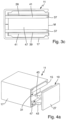
- FIG. 3 an embodiment of a slide rail 11 according to the invention according to the third exemplary embodiment is described.
- the third exemplary embodiment differs from the previous exemplary embodiments both in the specific design of the respective coupling sections 29 and in the design of the receiving openings 31 of the fastening elements 15. The detailed description of the remaining identical features is omitted here.
- the coupling section 29 has a substantially rectangular cross section with two wall sections 37 aligned parallel to one another. These are separated from one another by a recess 47 which is open on the transversely opposite sides and are formed from a resiliently deformable material. For the assembled state of the slide rail 11, this allows a resilient deformation of the two wall sections 37 towards each other transversely to the axial direction A, in order to brace the coupling sections 29 in the corresponding receiving openings 31.
- the corresponding receiving openings 31 also each have a rectangular cross section and are open on the two transversely opposite sides. This allows the respective end cap 19 to be displaced relative to the corresponding fastening element 15 transversely to the axial direction A over a larger area, since the coupling sections 29 can each protrude laterally beyond the corresponding receiving opening 31.
- the coupling sections 29 of the end caps 19 each have a corrugation 39 running transversely to the axial direction A on the circumferential outer surfaces of the parallel wall sections 37.
- the inner surfaces of the corresponding receiving openings 31 each have corresponding engagement surfaces 41 which are grooved transversely to the axial direction A.
- the said corrugations 39 engage with the correspondingly corrugated engagement surfaces 41 in order to hold the respective end cap 19 on the corresponding fastening element 15.
- the resilient deformation of the wall sections 37 ensures a corresponding adhesion. This design is particularly specialized because different corrugations cannot easily be interchanged with one another, but can be tailored particularly precisely to the respective requirements.
- the fourth exemplary embodiment also differs from the previous exemplary embodiments in the specific design of the respective coupling sections 29 and in the design of the receiving openings 31 of the fastening elements 15. The detailed description of the remaining identical features is omitted here.
- the coupling section 29 of the fourth exemplary embodiment also has a rectangular cross section, which is formed by two wall sections 37 which run parallel to one another transversely to the axial direction A. These are separated from each other by a laterally open recess 47 and can be elastically deformed towards one another transversely to the axial direction A.
- the two wall sections 37 are inclined away from each other with respect to the axial direction A in order to form greater restoring forces and consequently an even stronger adhesion in the assembled state.
- the rectangular shaped and laterally open receiving openings 31 also have instead of the corrugated engagement surfaces 41 of the third exemplary embodiment their front ends each have a cross-sectional reduction 45. If necessary, this can also form an undercut.
- the two wall sections 37 are provided here with locking lugs 43 instead of corrugations 39.
- these locking lugs 43 are non-positively engaged with the respective cross-sectional reduction 45 for fixing the respective end cap 19 on the corresponding fastening element 15.
- the resilient deformability of the wall sections 37 allows the coupling sections 29 to be inserted and then forms the frictional connection in the assembled state of the slide rail 11.
- the engagement between the locking lugs 43 and the cross-sectional reductions 45 can also be formed in a form-fitting manner (i.e. in particular via an undercut), if this is desired.
- Such a configuration allows the end caps 19 to be fixed to the corresponding fastening elements 15 particularly firmly and possibly not in a non-destructive manner.
- the locking lugs 43 each have a ramp-shaped section. This rests on the cross-sectional reduction 45 and is designed in such a way that it generates a preload of the respective end cap 19 acting in the axial direction A into the receiving opening 31 of the corresponding fastening element 15. This means that the respective end cap 19 is able to independently adjust its specific relative positioning along the axial direction A with respect to the corresponding fastening element 15.
- the exemplary embodiments shown differ from one another only in the specific design of the receiving openings 31 and the coupling sections 29. However, this should not be interpreted as a limitation of the scope of protection. Of course, further differences can also arise between individual embodiments, provided this is expedient and/or desired.
- the two fastening elements 15 are designed identically to one another and are symmetrical to a vertical plane along the axial direction A (i.e. to the image plane in the Figures 1b ), 2 B ), 3b ) and 4b )) are shaped.
- the respective end caps 19 are also designed in pairs identical to one another and designed symmetrically to the said vertical plane. It is therefore possible to use only one type of fastening element 15 and one type of end cap 19 per embodiment. This enables significant cost savings in manufacturing and makes assembly easier.
Landscapes
- Bearings For Parts Moving Linearly (AREA)
Applications Claiming Priority (1)
| Application Number | Priority Date | Filing Date | Title |
|---|---|---|---|
| DE102022205376.1A DE102022205376B4 (de) | 2022-05-30 | 2022-05-30 | Gleitschiene für einen Türantrieb |
Publications (1)
| Publication Number | Publication Date |
|---|---|
| EP4286636A1 true EP4286636A1 (fr) | 2023-12-06 |
Family
ID=86331179
Family Applications (1)
| Application Number | Title | Priority Date | Filing Date |
|---|---|---|---|
| EP23172512.8A Pending EP4286636A1 (fr) | 2022-05-30 | 2023-05-10 | Rail de coulissement pour un entraînement de porte |
Country Status (2)
| Country | Link |
|---|---|
| EP (1) | EP4286636A1 (fr) |
| DE (1) | DE102022205376B4 (fr) |
Citations (3)
| Publication number | Priority date | Publication date | Assignee | Title |
|---|---|---|---|---|
| EP2078812A2 (fr) * | 2008-01-09 | 2009-07-15 | Dorma GmbH + CO. KG | Elément de recouvrement pour un rail de guidage |
| EP1727955B1 (fr) * | 2004-03-12 | 2010-06-23 | Dorma Gmbh & Co. Kg | Glissiere pour systeme de fermeture de porte ou analogue |
| EP2617927A2 (fr) * | 2012-01-19 | 2013-07-24 | DORMA GmbH + Co. KG | Agencement de rail de guidage |
Family Cites Families (4)
| Publication number | Priority date | Publication date | Assignee | Title |
|---|---|---|---|---|
| DE19804801C1 (de) | 1998-02-09 | 1999-07-08 | Dorma Gmbh & Co Kg | Befestigung von Endkappen an Gehäusen, die aus Profilen bestehen |
| US6484360B1 (en) | 2000-04-27 | 2002-11-26 | Hubbell Incorporated | Self-securing raceway end cap |
| DE102004008117A1 (de) | 2004-02-18 | 2005-09-01 | Dorma Gmbh + Co. Kg | Befestigungsvorrichtung für eine Gleit- oder Führungsschiene |
| ATE449230T1 (de) | 2007-01-12 | 2009-12-15 | Hautau Gmbh | Endabdeckung für ein gehäuse eines stellantriebs und verfahren der anordnung des gehäuses eines stellantriebs |
-
2022
- 2022-05-30 DE DE102022205376.1A patent/DE102022205376B4/de active Active
-
2023
- 2023-05-10 EP EP23172512.8A patent/EP4286636A1/fr active Pending
Patent Citations (3)
| Publication number | Priority date | Publication date | Assignee | Title |
|---|---|---|---|---|
| EP1727955B1 (fr) * | 2004-03-12 | 2010-06-23 | Dorma Gmbh & Co. Kg | Glissiere pour systeme de fermeture de porte ou analogue |
| EP2078812A2 (fr) * | 2008-01-09 | 2009-07-15 | Dorma GmbH + CO. KG | Elément de recouvrement pour un rail de guidage |
| EP2617927A2 (fr) * | 2012-01-19 | 2013-07-24 | DORMA GmbH + Co. KG | Agencement de rail de guidage |
Also Published As
| Publication number | Publication date |
|---|---|
| DE102022205376B4 (de) | 2024-02-01 |
| DE102022205376A1 (de) | 2023-11-30 |
Similar Documents
| Publication | Publication Date | Title |
|---|---|---|
| DE69804149T2 (de) | Verriegelungshebelmechanismus für Verbinder | |
| DE3214528C2 (de) | Vorrichtung zur Festlegung von Instrumentengehäusen in einer Trägerplatte | |
| EP3688337B1 (fr) | Dispositif de guidage | |
| DE3838957C2 (fr) | ||
| EP1022832A2 (fr) | Dispositif de maintien pour cable traversant un mur de manière étanche | |
| DE19639109B4 (de) | Längsführung für einen Fahrzeugsitz mit einem Schienenpaar bestehend aus einer Sitzschiene und einer Bodenschiene | |
| EP4286636A1 (fr) | Rail de coulissement pour un entraînement de porte | |
| EP0104340A2 (fr) | Agencement, en particulier pour une cloison de douche | |
| DE69510627T2 (de) | Geräteträgereinrichtung Einzubringen auf einen Kabelkanalkörper | |
| EP1992779A2 (fr) | Barre de charge pour écran de fenêtre | |
| DE102013100308A1 (de) | Riegelstangenbeschlag für ein Fenster oder eine Tür | |
| DE2208289C2 (de) | Belüftungsvorrichtung | |
| DE202007008150U1 (de) | Befestigungsvorrichtung für Solarmodule | |
| EP0853353B1 (fr) | Utité de ressort de contact realisant une fonction de commutation | |
| DE29508292U1 (de) | Befehlsgerät | |
| WO2003030322A1 (fr) | Socle pour un coffret de distribution | |
| EP4202171B1 (fr) | Joint automatique d'étanchéité comportant un support, des éléments de raccordement et une baguette d'étanchéité, comprenant une baguette de maintien et un élément d'étanchéité | |
| EP2594704B1 (fr) | Agencement des lames de bois massif | |
| DE69926265T2 (de) | Einbaugerät-befestigungsvorrichtung für kabelkanalsockel | |
| EP0455236A1 (fr) | Dispositif de fixation de rail | |
| DE4416698C2 (de) | Befestigungsvorrichtung zur Wandbefestigung von Hängeteilen | |
| EP2230374A2 (fr) | Profil d'étanchéité en forme de tronçon | |
| DE102007009667A1 (de) | Profilkonstruktion | |
| DE102016124949B4 (de) | Adaptervorrichtung für ein Schiebetürsystem sowie Schiebetürsystem | |
| CH653793A5 (de) | Halter fuer nummerntafel. |
Legal Events
| Date | Code | Title | Description |
|---|---|---|---|
| PUAI | Public reference made under article 153(3) epc to a published international application that has entered the european phase |
Free format text: ORIGINAL CODE: 0009012 |
|
| STAA | Information on the status of an ep patent application or granted ep patent |
Free format text: STATUS: THE APPLICATION HAS BEEN PUBLISHED |
|
| AK | Designated contracting states |
Kind code of ref document: A1 Designated state(s): AL AT BE BG CH CY CZ DE DK EE ES FI FR GB GR HR HU IE IS IT LI LT LU LV MC ME MK MT NL NO PL PT RO RS SE SI SK SM TR |
|
| STAA | Information on the status of an ep patent application or granted ep patent |
Free format text: STATUS: REQUEST FOR EXAMINATION WAS MADE |
|
| 17P | Request for examination filed |
Effective date: 20240410 |
|
| RBV | Designated contracting states (corrected) |
Designated state(s): AL AT BE BG CH CY CZ DE DK EE ES FI FR GB GR HR HU IE IS IT LI LT LU LV MC ME MK MT NL NO PL PT RO RS SE SI SK SM TR |
|
| GRAP | Despatch of communication of intention to grant a patent |
Free format text: ORIGINAL CODE: EPIDOSNIGR1 |
|
| STAA | Information on the status of an ep patent application or granted ep patent |
Free format text: STATUS: GRANT OF PATENT IS INTENDED |
|
| INTG | Intention to grant announced |
Effective date: 20240610 |
|
| GRAS | Grant fee paid |
Free format text: ORIGINAL CODE: EPIDOSNIGR3 |
|
| GRAA | (expected) grant |
Free format text: ORIGINAL CODE: 0009210 |
|
| STAA | Information on the status of an ep patent application or granted ep patent |
Free format text: STATUS: THE PATENT HAS BEEN GRANTED |
|
| P01 | Opt-out of the competence of the unified patent court (upc) registered |
Free format text: CASE NUMBER: APP_45099/2024 Effective date: 20240805 |