EP4286494A2 - Mehrwegeventil - Google Patents
Mehrwegeventil Download PDFInfo
- Publication number
- EP4286494A2 EP4286494A2 EP23203348.0A EP23203348A EP4286494A2 EP 4286494 A2 EP4286494 A2 EP 4286494A2 EP 23203348 A EP23203348 A EP 23203348A EP 4286494 A2 EP4286494 A2 EP 4286494A2
- Authority
- EP
- European Patent Office
- Prior art keywords
- valve
- outlet
- control element
- flow control
- ball
- Prior art date
- Legal status (The legal status is an assumption and is not a legal conclusion. Google has not performed a legal analysis and makes no representation as to the accuracy of the status listed.)
- Granted
Links
Images


Classifications
-
- F—MECHANICAL ENGINEERING; LIGHTING; HEATING; WEAPONS; BLASTING
- F16—ENGINEERING ELEMENTS AND UNITS; GENERAL MEASURES FOR PRODUCING AND MAINTAINING EFFECTIVE FUNCTIONING OF MACHINES OR INSTALLATIONS; THERMAL INSULATION IN GENERAL
- F16K—VALVES; TAPS; COCKS; ACTUATING-FLOATS; DEVICES FOR VENTING OR AERATING
- F16K11/00—Multiple-way valves, e.g. mixing valves; Pipe fittings incorporating such valves
- F16K11/02—Multiple-way valves, e.g. mixing valves; Pipe fittings incorporating such valves with all movable sealing faces moving as one unit
- F16K11/08—Multiple-way valves, e.g. mixing valves; Pipe fittings incorporating such valves with all movable sealing faces moving as one unit comprising only taps or cocks
- F16K11/087—Multiple-way valves, e.g. mixing valves; Pipe fittings incorporating such valves with all movable sealing faces moving as one unit comprising only taps or cocks with spherical plug
- F16K11/0873—Multiple-way valves, e.g. mixing valves; Pipe fittings incorporating such valves with all movable sealing faces moving as one unit comprising only taps or cocks with spherical plug the plug being only rotatable around one spindle
- F16K11/0876—Multiple-way valves, e.g. mixing valves; Pipe fittings incorporating such valves with all movable sealing faces moving as one unit comprising only taps or cocks with spherical plug the plug being only rotatable around one spindle one connecting conduit having the same axis as the spindle
-
- F—MECHANICAL ENGINEERING; LIGHTING; HEATING; WEAPONS; BLASTING
- F16—ENGINEERING ELEMENTS AND UNITS; GENERAL MEASURES FOR PRODUCING AND MAINTAINING EFFECTIVE FUNCTIONING OF MACHINES OR INSTALLATIONS; THERMAL INSULATION IN GENERAL
- F16K—VALVES; TAPS; COCKS; ACTUATING-FLOATS; DEVICES FOR VENTING OR AERATING
- F16K5/00—Plug valves; Taps or cocks comprising only cut-off apparatus having at least one of the sealing faces shaped as a more or less complete surface of a solid of revolution, the opening and closing movement being predominantly rotary
- F16K5/06—Plug valves; Taps or cocks comprising only cut-off apparatus having at least one of the sealing faces shaped as a more or less complete surface of a solid of revolution, the opening and closing movement being predominantly rotary with plugs having spherical surfaces; Packings therefor
- F16K5/0626—Easy mounting or dismounting means
- F16K5/0636—Easy mounting or dismounting means the spherical plug being insertable from the top of the housing
-
- C—CHEMISTRY; METALLURGY
- C10—PETROLEUM, GAS OR COKE INDUSTRIES; TECHNICAL GASES CONTAINING CARBON MONOXIDE; FUELS; LUBRICANTS; PEAT
- C10B—DESTRUCTIVE DISTILLATION OF CARBONACEOUS MATERIALS FOR PRODUCTION OF GAS, COKE, TAR, OR SIMILAR MATERIALS
- C10B31/00—Charging devices
- C10B31/12—Charging devices for liquid materials
-
- C—CHEMISTRY; METALLURGY
- C10—PETROLEUM, GAS OR COKE INDUSTRIES; TECHNICAL GASES CONTAINING CARBON MONOXIDE; FUELS; LUBRICANTS; PEAT
- C10B—DESTRUCTIVE DISTILLATION OF CARBONACEOUS MATERIALS FOR PRODUCTION OF GAS, COKE, TAR, OR SIMILAR MATERIALS
- C10B55/00—Coking mineral oils, bitumen, tar, and the like or mixtures thereof with solid carbonaceous material
-
- E—FIXED CONSTRUCTIONS
- E21—EARTH OR ROCK DRILLING; MINING
- E21B—EARTH OR ROCK DRILLING; OBTAINING OIL, GAS, WATER, SOLUBLE OR MELTABLE MATERIALS OR A SLURRY OF MINERALS FROM WELLS
- E21B7/00—Special methods or apparatus for drilling
- E21B7/28—Enlarging drilled holes, e.g. by counterboring
-
- F—MECHANICAL ENGINEERING; LIGHTING; HEATING; WEAPONS; BLASTING
- F16—ENGINEERING ELEMENTS AND UNITS; GENERAL MEASURES FOR PRODUCING AND MAINTAINING EFFECTIVE FUNCTIONING OF MACHINES OR INSTALLATIONS; THERMAL INSULATION IN GENERAL
- F16K—VALVES; TAPS; COCKS; ACTUATING-FLOATS; DEVICES FOR VENTING OR AERATING
- F16K27/00—Construction of housing; Use of materials therefor
- F16K27/06—Construction of housing; Use of materials therefor of taps or cocks
- F16K27/067—Construction of housing; Use of materials therefor of taps or cocks with spherical plugs
-
- F—MECHANICAL ENGINEERING; LIGHTING; HEATING; WEAPONS; BLASTING
- F16—ENGINEERING ELEMENTS AND UNITS; GENERAL MEASURES FOR PRODUCING AND MAINTAINING EFFECTIVE FUNCTIONING OF MACHINES OR INSTALLATIONS; THERMAL INSULATION IN GENERAL
- F16K—VALVES; TAPS; COCKS; ACTUATING-FLOATS; DEVICES FOR VENTING OR AERATING
- F16K5/00—Plug valves; Taps or cocks comprising only cut-off apparatus having at least one of the sealing faces shaped as a more or less complete surface of a solid of revolution, the opening and closing movement being predominantly rotary
- F16K5/06—Plug valves; Taps or cocks comprising only cut-off apparatus having at least one of the sealing faces shaped as a more or less complete surface of a solid of revolution, the opening and closing movement being predominantly rotary with plugs having spherical surfaces; Packings therefor
- F16K5/0663—Packings
- F16K5/0689—Packings between housing and plug
-
- F—MECHANICAL ENGINEERING; LIGHTING; HEATING; WEAPONS; BLASTING
- F16—ENGINEERING ELEMENTS AND UNITS; GENERAL MEASURES FOR PRODUCING AND MAINTAINING EFFECTIVE FUNCTIONING OF MACHINES OR INSTALLATIONS; THERMAL INSULATION IN GENERAL
- F16K—VALVES; TAPS; COCKS; ACTUATING-FLOATS; DEVICES FOR VENTING OR AERATING
- F16K11/00—Multiple-way valves, e.g. mixing valves; Pipe fittings incorporating such valves
- F16K11/02—Multiple-way valves, e.g. mixing valves; Pipe fittings incorporating such valves with all movable sealing faces moving as one unit
- F16K11/04—Multiple-way valves, e.g. mixing valves; Pipe fittings incorporating such valves with all movable sealing faces moving as one unit comprising only lift valves
- F16K11/056—Multiple-way valves, e.g. mixing valves; Pipe fittings incorporating such valves with all movable sealing faces moving as one unit comprising only lift valves with ball-shaped valve members
-
- F—MECHANICAL ENGINEERING; LIGHTING; HEATING; WEAPONS; BLASTING
- F16—ENGINEERING ELEMENTS AND UNITS; GENERAL MEASURES FOR PRODUCING AND MAINTAINING EFFECTIVE FUNCTIONING OF MACHINES OR INSTALLATIONS; THERMAL INSULATION IN GENERAL
- F16K—VALVES; TAPS; COCKS; ACTUATING-FLOATS; DEVICES FOR VENTING OR AERATING
- F16K11/00—Multiple-way valves, e.g. mixing valves; Pipe fittings incorporating such valves
- F16K11/02—Multiple-way valves, e.g. mixing valves; Pipe fittings incorporating such valves with all movable sealing faces moving as one unit
- F16K11/08—Multiple-way valves, e.g. mixing valves; Pipe fittings incorporating such valves with all movable sealing faces moving as one unit comprising only taps or cocks
- F16K11/087—Multiple-way valves, e.g. mixing valves; Pipe fittings incorporating such valves with all movable sealing faces moving as one unit comprising only taps or cocks with spherical plug
-
- F—MECHANICAL ENGINEERING; LIGHTING; HEATING; WEAPONS; BLASTING
- F16—ENGINEERING ELEMENTS AND UNITS; GENERAL MEASURES FOR PRODUCING AND MAINTAINING EFFECTIVE FUNCTIONING OF MACHINES OR INSTALLATIONS; THERMAL INSULATION IN GENERAL
- F16K—VALVES; TAPS; COCKS; ACTUATING-FLOATS; DEVICES FOR VENTING OR AERATING
- F16K5/00—Plug valves; Taps or cocks comprising only cut-off apparatus having at least one of the sealing faces shaped as a more or less complete surface of a solid of revolution, the opening and closing movement being predominantly rotary
- F16K5/06—Plug valves; Taps or cocks comprising only cut-off apparatus having at least one of the sealing faces shaped as a more or less complete surface of a solid of revolution, the opening and closing movement being predominantly rotary with plugs having spherical surfaces; Packings therefor
- F16K5/0605—Plug valves; Taps or cocks comprising only cut-off apparatus having at least one of the sealing faces shaped as a more or less complete surface of a solid of revolution, the opening and closing movement being predominantly rotary with plugs having spherical surfaces; Packings therefor with particular plug arrangements, e.g. particular shape or built-in means
-
- F—MECHANICAL ENGINEERING; LIGHTING; HEATING; WEAPONS; BLASTING
- F16—ENGINEERING ELEMENTS AND UNITS; GENERAL MEASURES FOR PRODUCING AND MAINTAINING EFFECTIVE FUNCTIONING OF MACHINES OR INSTALLATIONS; THERMAL INSULATION IN GENERAL
- F16K—VALVES; TAPS; COCKS; ACTUATING-FLOATS; DEVICES FOR VENTING OR AERATING
- F16K5/00—Plug valves; Taps or cocks comprising only cut-off apparatus having at least one of the sealing faces shaped as a more or less complete surface of a solid of revolution, the opening and closing movement being predominantly rotary
- F16K5/06—Plug valves; Taps or cocks comprising only cut-off apparatus having at least one of the sealing faces shaped as a more or less complete surface of a solid of revolution, the opening and closing movement being predominantly rotary with plugs having spherical surfaces; Packings therefor
- F16K5/0663—Packings
Definitions
- a coker switch valve is often used to divert a flow of heavy oil from one coke drum to another.
- Typical temperatures of the process stream are over 200°C and sometimes as high as 500°C, with typical times between switching coke drums of 16 to 24 hours.
- the heavy oil will turn into coke when held at these temperatures for several hours. If heavy oil enters and forms coke in the valve cavity or seats, the CSV may seize.
- switching of the CSV during production results in a brief interruption, typically a 40 % reduction in process flow.
- the transient flow restriction can result in hot spots within the heaters, coke deposition, fouling, and so on, leading to early maintenance requirements and/or equipment failure.
- the firing rate in the heaters and/or the flow rate are reduced for the switching operation, which complicates the switching process and reduces efficiencies.
- the prior art CSVs are typically purged with steam, which constantly flows into the process streams, even between switching operations. Steam consumption can be excessive, and yet process fluid can still enter and form coke in the seats and valve body cavity around the ball.
- Patent document US 2018/0003304 discloses an attempt to maintain a flow of the heavy oil through the valve cavity around the ball to avoid dead spots where coke could form. This reference discloses apertures to maintain fluid flow between the process media flowing through the ball and the area in the valve cavity around the bellows seals. Other patent documents promoting the flow of process media into the valve cavity include US 5,185,539 and US 2012/0012770 .
- Applicant herein addresses many problems associated with prior art coker switching valves or CSVs by providing embodiments of a multiport valve with a sealed semi-trunnion arrangement to support the spherical flow control element, hereinafter sometimes referred to as the ball.
- a lower part of the outlet seat recesses is formed in the main body of the valve, while the upper part of the outlet seat recesses is formed in the bonnet.
- the bonnet and body together bias a respective resilient member such as a Belleville resilient member to load the seat, maintaining alignment of the ball and equalizing stresses, independently of end connection loads.
- the outlet of the ball can have a larger bore than the ball inlet such that the outlet flow area is larger, e.g., at least 50% larger area than the inlet.
- the present design in various embodiments overcomes many drawbacks of the prior art CSVs by providing one or more of the following exemplary advantages: the present design maintains alignment of the ball and equalizes wiping forces, inhibits or prevents uneven seat loading and leakage, reduces the number of potential leak paths, reduces operating torque, simplifies repair and trim replacement, can eliminate bellows resilient members and associated steam purge inlets, can simplify steam purging, increases switching reliability, can evacuate body cavity of process media before and after switching, requires appreciable steam consumption only during switching, reduces steam consumption between switching operations, lowers overall steam consumption, minimizes the entry of process media into the valve body cavity, provides less interruption of process flow during switching, and so on.
- a multiport valve as set out in the first of the appending independent claims.
- a method of operating a coker switch valve as set out in the second of the appending independent claims.
- a multiport valve comprising: a valve body comprising a flow path between a body inlet coaxial to a first axis and a plurality of body outlets each oriented at an angle transverse to the first axis; and a spherical flow control element disposed within a cavity, wherein the flow control element comprises a ball inlet having a ball inlet area radially arranged about the first axis, and a ball outlet having a ball outlet area larger than the ball inlet area, radially arranged at the transverse angle to the first axis, the flow control element rotatable about the first axis to selectively align the ball outlet with each of the plurality of body outlets separately and to overlap the ball outlet with portions of two of the body outlets.
- the body outlets can have a cross-sectional flow area tapering down from adjacent to the flow control element to an end connection, e.g., matching the ball outlet area adjacent to the flow control element and matching the ball inlet area at the end connections.
- a multiport valve comprising: a valve body comprising a flow path between a body inlet coaxial to a first axis and a plurality of body outlets each oriented at an angle transverse to the first axis.
- a spherical flow control element is disposed within a cavity of the valve body comprising a ball inlet having a ball inlet area radially arranged about the first axis, and a ball outlet radially arranged at the transverse angle to the first axis.
- the flow control element is rotatable about the first axis to selectively align the ball outlet with each of the plurality of body outlets separately, and to overlap the ball outlet with portions of two of the body outlets.
- the valve comprises a like plurality of outlet seat recesses. Each outlet seat recess is radially arranged about a respective one of the body outlets, and each receives a respective outlet valve seat assembly in sealing engagement between the valve body and the flow control element.
- the valve comprises a like plurality of resilient members, and each biases a respective one of the outlet valve seat assemblies against the flow control assembly.
- An inlet sleeve assembly is radially arranged about the body inlet in sealing, biased engagement between the valve body and the flow control element.
- the valve body comprises a lower main body sealingly engaged with an upper bonnet. The body inlet is disposed through the main body. A portion of each body outlet is formed through the main body and a remaining portion of each body outlet is formed by the bonnet.
- each outlet seat recess is formed into the main body, whereby a corresponding lower portion of each resilient member is biased against the main body.
- An upper portion of each outlet seat recess is formed into the bonnet, whereby a corresponding upper portion of each resilient member is biased against the bonnet.
- a method of operating a coker switch valve comprising: (a) providing the multiport valve described herein; (b) continuously supplying steam to a plurality of steam purge inlets to the body cavity; (c) rotating the flow control element to switch alignment of the ball outlet from one of the body outlets to another one of the body outlets while maintaining the steam supply; (d) continuously flowing process media through the flow path while rotating the flow control element; and (e) draining the steam and process media from the cavity after the alignment switching.
- the assembly method comprises: (a) inserting the inlet sleeve assembly into engagement with the main body about the body inlet; (b) inserting the flow control element into the main body to engage the inlet sleeve assembly; (c) inserting each of the outlet valve seat assemblies and resilient members into the lower portion of the outlet seat recesses, wherein each insertion comprises: (i) orienting the ball outlet towards one of the body outlets; (ii) inserting one of the outlet seat assemblies into the lower portion of the respective outlet seat recess; and (iii) sliding the respective outlet seat assembly into engagement with the flow control element; and (d) engaging the bonnet with the main body to bias the upper portions of the resilient members against respective upper portions of the outlet seat assemblies.
- the servicing method comprises: (a) removing the bonnet from the main body; (b) removing each of the outlet valve seat assemblies and resilient members from the main body, wherein the removal comprises: (i) orienting the ball outlet towards a one of the body outlets; (ii) removing the respective resilient member from the lower portion of the respective outlet seat recess; and (iii) disengaging the respective outlet seat assembly from the lower portion of the respective outlet seat recess; (c) removing the flow control element from the main body; and (d) removing the inlet sleeve assembly from the main body.
- the instant disclosure is directed to a multiport valve comprising a flow control element, sometimes referred to herein as a ball, disposed within a valve body having a selectable flow path between a body inlet and a plurality of body outlets each oriented at an angle transverse to the inlet.
- a flow control element sometimes referred to herein as a ball
- a multiport valve comprises a valve body comprising a flow path between a body inlet coaxial to a first axis and a plurality of body outlets each oriented at an angle transverse to the first axis.
- a spherical flow control element is disposed within a cavity of the valve body.
- the flow control element comprises a ball inlet having an area radially arranged about the first axis.
- a ball outlet is radially arranged at the transverse angle to the first axis, and has an outlet area larger than the ball inlet area, preferably at least 50% larger, more preferably at least 65% larger.
- the flow control element is preferably rotatable about the first axis to selectively align the ball outlet with each of the plurality of body outlets separately, and to overlap the ball outlet with portions of two of the body outlets.
- the body outlets have a cross-sectional flow area tapering down from adjacent to the flow control element to an end connection.
- the valve can also have a like plurality of outlet valve seat assembly recesses.
- Each valve seat recess can be radially arranged about a respective one of the body outlets.
- Each valve seat recess can receive a respective outlet valve seat assembly in sealing engagement between the valve body and the flow control element.
- the valve can also have a like plurality of resilient members, each biased between the valve body and a respective one of the outlet valve seat assemblies.
- An inlet sleeve assembly can be radially arranged about the body inlet in sealing, biased engagement between the valve body and the flow control element.
- the valve body can comprise a lower main body sealingly engaged with an upper bonnet, wherein the body inlet is disposed through the main body, and wherein a portion of each body outlet is formed through the main body and a remaining portion of each body outlet is formed by the bonnet.
- a lower portion of each outlet seat recess can be formed into the main body, whereby a corresponding lower portion of each resilient member is biased against the main body.
- An upper portion of each outlet seat recess can be formed into the bonnet, whereby a corresponding upper portion of each resilient member is biased against the bonnet.
- the flow control element, the outlet valve seat assemblies, the resilient members, the inlet sleeve assembly, and the outlet seat recesses can be dimensioned and arranged to allow sequential removal of the resilient members, disengagement of the outlet valve seat assemblies from the flow control element, removal of the outlet valve seat assemblies, removal of the flow control element, and removal of the inlet sleeve assembly from the valve body exclusively through an opening created by disengagement of the bonnet from the main valve body.
- the flow control element, the outlet valve seat assemblies, the resilient members, the inlet sleeve assembly, and the outlet seat recesses can be dimensioned and arranged to allow sequential insertion of the inlet sleeve assembly into the valve body, insertion of the flow control element into the valve body, insertion of the outlet valve seat assemblies and engagement with the flow control element, the insertion of the resilient members into the outlet seat recesses, exclusively through the opening created by disengagement of the bonnet from the valve body.
- a maximum distance between an outer edge of the spherical flow control element and an inner surface of the outlet seat recesses is less than 1 cm.
- the cross-sectional flow area of the body outlets can match the ball outlet area adjacent to the flow control element, and can match the ball inlet area at the end connections.
- a multiport valve can comprise a valve body comprising a body inlet coaxial to a first axis and a plurality of body outlets each oriented at an angle transverse to the first axis; and a spherical flow control element disposed within a cavity of the valve body comprising a ball inlet having a ball inlet area radially arranged about the first axis, and a ball outlet radially arranged at the transverse angle to the first axis.
- the flow control element is rotatable about the first axis to selectively align the ball outlet with each of the plurality of body outlets separately, and preferably also rotatable to overlap the ball outlet with portions of two of the body outlets.
- the valve further comprises: a like plurality of outlet seat recesses, each outlet seat recess radially arranged about a respective one of the body outlets, each outlet seat recess receiving a respective outlet valve seat assembly in sealing engagement between the valve body and the flow control element; a like plurality of resilient members, each biasing a respective one of the outlet valve seat assemblies against the valve body; and an inlet sleeve assembly radially arranged about the body inlet in sealing, biased engagement between the valve body and the flow control element.
- the valve body can comprise a lower main body sealingly engaged with an upper bonnet. A lower portion of each outlet seat recess is formed into the main body, whereby a corresponding lower portion of each resilient member is biased against the main body. Similarly, an upper portion of each outlet seat recess is formed into the bonnet, whereby a corresponding upper portion of each resilient member is biased against the bonnet.
- the main body can comprise U-shaped recesses defining the lower portions of the outlet seat recesses and alignment guideways to receive respective alignment ribs of the bonnet.
- valve can further comprise a valve stem extending from the flow control element through an opening through the bonnet, whereby the flow control element can be rotated by rotating the stem to switch alignment of the ball outlet with a selected one of the body outlets.
- the valve can also comprise a stem thrust bearing and a bushing oriented about the stem in rotational contact between a surface disposed into the spherical flow control element and a corresponding surface disposed into the bonnet radially about the valve stem opening.
- the inlet sleeve assembly can comprise a sleeve member, a sleeve resilient member biased between the main body and a lower end of the sleeve member, a sleeve bearing disposed between an upper end of the sleeve member and a circular groove formed in a lower end of the flow control element, and one or more seal rings disposed between the sleeve member, the flow control element, and/or the main body.
- valve can further comprise respective biasing portions formed in the upper portions of the outlet valve seat assembly recesses arranged to engage the respective resilient members.
- the outlet valve seat assemblies can preferably respectively comprise one or more seals in sealing contact between a seat ring and the outlet seat recess, more preferably where the one or more seals are disposed within respective grooves disposed into an outer surface of the seat ring.
- the valve can comprise a purge inlet to the cavity between the valve body and the and flow control element, and a drain to remove purge fluid from the cavity between the body and the flow control element.
- an area of the ball outlet can be larger than an area of the ball inlet, e.g., at least 50% greater, or at least 65% greater.
- the body outlets have a cross-sectional flow area tapering down from adjacent to the flow control element to an end connection, e.g., the cross-sectional flow area of the body outlets matches the ball outlet area adjacent to the flow control element and matches the ball inlet area at the end connections.
- a method of operating a coker switch valve can comprise the steps of: (a) providing a multiport valve as described herein; (b) continuously supplying purge fluid such as steam to a plurality of steam purge inlets to the body cavity; (c) rotating the flow control element to switch alignment of the ball outlet from one of the body outlets to another one of the body outlets while maintaining the steam supply; (d) continuously flowing process media through the valve while rotating the flow control element; and (e) draining purge fluid and process media from the cavity after the alignment switching.
- the process media flow in step (d) can be maintained at a substantially constant rate immediately before, during, and immediately after the alignment switching, preferably wherein the switching maintains from 80 or 90 to 100 percent, e.g., 80-90 percent, of the process media flow relative to the process media flow immediately before and immediately after the switching.
- a volume of the purge fluid flow to the purge inlets, other than during switching in step (c) is limited to incidental leakage into process media.
- the invention provides embodiments of a method for servicing the valve described herein.
- the method comprises (a) removing the bonnet from the main body; (b) removing each of the outlet valve seat assemblies and resilient members from the main body, wherein the removal comprises: (i) orienting the ball outlet towards one of the body outlets; (ii) removing the respective resilient member from the lower portion of the respective outlet seat recess; (iii) disengaging the respective outlet seat assembly from the flow control element; and (iv) removing the respective outlet seat assembly from the lower portion of the respective outlet seat recess; (c) removing the flow control element from the main body; and (d) removing the inlet sleeve assembly from the main body.
- the removal steps (a) to (d) are conducted in-line while the valve remains attached to process piping at end connections at the body inlet and at one or more body outlets.
- removing the resilient member from the main body can comprise: (I) providing a resilient member removal tool comprising a bottom appendage dimensioned to fit into the lower portion of the outlet seat recess between the main body and the resilient member, and a selectively retractable/extendable portion dimensioned to extend away from a face of the tool to engage an inner edge of the resilient member after the tool is inserted into position between the resilient member and the main body; (II) inserting the bottom appendage of the resilient member removal tool into the lower portion of the outlet seat recess between the resilient member and the main body until the extendable portion of the resilient member removal tool is positioned to engage the inner edge of a corresponding resilient member; (III) actuating the tool to extend the extendable portion towards the center of the valve away from the face of tool in an amount sufficient to engage the inner edge of the resilient member, and (IV) removing the tool from the lower portion of the outlet seat recess together with the resilient member.
- a resilient member removal tool comprising a bottom appendage dimensioned to
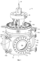
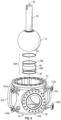
- FIG. 1 is a perspective view of the valve 10 of the invention showing the assembled valve body 12, bonnet 62, and optional top works 96;
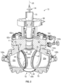
- FIG. 2 is a cut away view showing ball 14 and preferred steam manifold 140a;
- FIG. 3 is a side sectional view showing preferred steam manifold 140b and optional actuator 108.
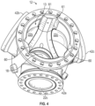
- the valve 10 has two main pieces, a bottom piece or main valve body 12 ( FIG. 4 ) and a top piece or bonnet 62 ( FIG. 8 ), attached by means of studs 62a and nuts 62b ( FIGs. 1-3 ).
- process media entry into the valve 10 is from the bottom of the valve body 12 into the ball 14 following flow path 16 to transverse angle.
- the fluid passes from body inlet 18, into ball inlet 24 along central axis 20, to transverse ball outlet 28 formed at transverse angle 33, preferably 90 degrees with respect to axis 20, and then exits through one of three body outlets 22a, 22b, 22c, which are generically referred to herein as body outlet(s) 22.
- the body outlets 22 are radially spaced in the valve body at equal intervals, i.e., 120° apart and are oriented at angle 33 (e.g., 90°) to the body inlet 18.
- valve 10 is not limited to CSVs, but when the valve 10 is used as a CSV, outlet 22a typically directs flow to delayed coker drum A (not shown), outlet 22b to drum B (not shown), and outlet 22c to bypass the drums and recirculate to a heater (not shown).
- outlet 22a typically directs flow to delayed coker drum A (not shown), outlet 22b to drum B (not shown), and outlet 22c to bypass the drums and recirculate to a heater (not shown).
- the valve 10 is illustrated herein with three outlets, it is also contemplated that it could have two outlets 180° apart or four outlets 90° apart, and so on.
- the valve 10 has a flanged inlet connection 78 and flanged outlet connections 42a, 42b, 42c (generically, 42), each of which is integral to the valve body 12.
- the outlet valve seat assemblies 44A are located independently within the valve body 12 and bonnet 62, without using bellows springs in a sleeve arrangement in each outlet that is common in the art.
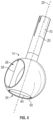
- the ball 14 ( FIG. 5 ) is provided with an integral valve stem 70 which passes through opening 64 in bonnet 12 ( FIG. 8 ), often through a top works 124 to a powered actuator 108 ( FIG. 3 ) by which the ball 14 can be rotated to the desired switching position, or it can be stroked manually using an appropriate wrench (not shown).
- the ball 14 is supported on the bottom by a semi-trunnion sleeve assembly 48A at the inlet 24.
- the sleeve assembly 48A is comprised of sleeve 58, sleeve bearing 52 between the sleeve 48 and the ball 14, sleeve resilient member 56, such as a Belleville resilient member, between the sleeve 48 and the valve body 12, and sleeve seal rings 58 above and below the sleeve 48.
- the supporting sleeve assembly 48A engages a corresponding groove 50 disposed into the bottom of the ball 14 to allow sealing rotation of the ball 14 about central axis 20.
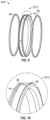
- seat assemblies 44A comprise seals 80 disposed in grooves 36 of seat ring 44.
- the ball 14 is centered by the outlet seat assemblies 44A around each of the outlets 22a, 22b, 22c. Since the ball 14 is not floating and is supported mainly by the sleeve assembly 48A, the loading on the outlet seat assemblies 44A can be reduced, which in turn reduces the torque required to rotate the ball 14 during switching operations.
- the main valve body 12 defines the fluid entry port 18 and flange 78 ( FIGs. 2-3 ), most of the valve outlets 22, and the flanges 42, and a lower portion 60 of each of the outlet recesses 68 in which lower portions of the outlet valve seat assemblies 44A and retaining resilient members 46 are located.
- An upper portion 66 of the seat recesses 68 is formed in a lower portion of the bonnet 62.
- the bonnet 62 thus forms the upper recess portions 66 in which each outlet valve seat assembly 44A and a corresponding retaining resilient member 46 are located.
- the seat recesses 68 are bisected between the body 12 and the bonnet 62, which allows for removal of the bonnet 62 to expose and access the valve seat assemblies 44A and the corresponding resilient members 46.
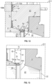
- FIG. 12 shows the enlarged detail D12 from FIG. 3 where the bonnet 62 is engaged with the main valve body 12, the ball stem 14, the valve seat assembly 44A and a corresponding resilient member 46.
- the bonnet 12 engages and biases the upper portion of the resilient member 46.
- the bonnet 62 has a chamfered surface 72 which engages the resilient member 46 to load the corresponding upper portion of the resilient member 46 against the outlet valve seat assembly 44A when the bonnet 62 is assembled to the main valve body 12.
- the end connections 78 and 42 can be connected to the process piping (not shown) before or after the assembly of the valve 10, as desired.
- the sleeve assembly 48A (see FIGs. 6-7 ) is installed on the shoulder 55 ( FIG. 7 ) in the cavity 94 ( FIG. 3 ) adjacent to the valve body inlet 18.
- the ball 14 is lowered into the main valve body 12 to engage the sleeve groove 50 with the sleeve bearing 52 of the sleeve assembly 48A.
- the ball 14 is turned to face one of the outlets 22a, 22b, 22c and the respective seat assembly 44A is inserted via alignment guideway recesses 61 into the corresponding seat recess lower portion 60 as shown in FIG. 13 .
- the dimension 74 of the recess 61 is greater than the width 76 of the seat assembly 44A and the nose portion 14a of the ball 14 residing therein.
- the seat assembly 44A is slid forward to engage the nose of the ball 14 as seen in FIG. 14 , and the resilient member 46 is inserted into the seat recess 60 as seen in FIG. 15 .
- Stem thrust bearing 57 and bushing 59 are slid onto the stem 70, and bonnet seal 88 and gasket 90 are positioned.
- the bonnet 62 is positioned on the main valve body 12, e.g., by lining up alignment ribs 63 formed on bonnet 62 to engage alignment guideway recesses 61 formed in the main valve body 12 as a projection of the lower set recess portions 60.
- the bonnet 62 is lowered into position on the main valve body 12, the chamfered surfaces 72 engage the respective resilient members 46 to load the corresponding upper portions of the resilient members 46 against the respective seat assemblies 44A.
- the bonnet 62 is then bolted to the main body 12 via studs 62a and bolts 62b.
- Packing assembly 109A installation includes sliding lantern ring 110, anti-extrusion ring 112a, packing rings 114, and anti-extrusion ring 112b on the stem 70, as best seen in FIG. 12 , and installation of gland studs 116, gland flange 118, live loading spring discs 120, and gland nuts 122. Then the top works 96 and actuator 108 are optionally installed.
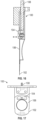
- a specially designed tool 100 as shown in FIGs. 16-18 can be used for removal of resilient members 46.
- the tool 100 has an appendage 102 which fits into the seat recess 68 between the valve body 12 and the resilient member 46.
- the tool 100 further includes a selectively retractable/extendable portion 104, which extends away from the face 106 of the tool to engage the resilient member 46 once the tool 100 is inserted into position.
- the bonnet 62 is removed from the valve body 12.
- the outlet of the ball 14 is positioned to a valve outlet 22 and the resilient member removal tool 100 is inserted into the seat recess.
- the tool 100 is then actuated by rotating a threaded actuator 108 to extend the portion out from a face of the tool to engage the resilient member.
- the tool 100 is then withdrawn from the seat recess 68 together with the resilient member 46.
- the resilient member 46 may also be inserted using the tool 100 in a reverse manner.
- the true top bonnet access of the instant valve 10 allows for the resilient members 46 and seat assemblies 44A to be inserted and removed exclusively from the top, and thus in the field or other operational environment without disconnecting the inlet and outlet piping from end connections 42, 78. Furthermore, servicing the valve 10 in this manner does not affect the loading on any connected process piping since the end connections 42, 78 are integral to the valve body 10 and independent of the loading on the seat assemblies 48A and sleeve assembly 44A.
- the bisecting of the valve seat recesses between the main body and the bonnet also allows for a reduction in open space in the body cavity 94 between the inside surfaces of the body 12 and the opposing outside surfaces of the ball 14 (cf. FIGs. 4 and 12 ).
- the reduced annular volume 94 in this arrangement limits the amount of debris that can accumulate and improves the purge efficiency (higher space velocity).
- the maximum open space in the valve cavity between the inside surfaces of the body and the opposing outside surfaces of the ball is preferably less than 1 cm.
- the outlet flow passages 22 formed in the CSV body 12 can have a frustoconical taper from an enlarged cross-sectional area corresponding to the inside diameter 38 of the ball outlet bore 28, back down to the cross-sectional area corresponding to the inside diameter 40 of the area of the ball inlet bore 24, which often matches the ID of the body inlet 18, sleeve assembly 48A, and ball inlet 24.
- the relative flow area of the ball inlet 24 to the outlet 28 is from 1:1.5 to 1:500, preferably at least 1:1.5, and more preferably at least 1: 1.65.
- the outlet bore 28 of the ball preferably has an area of at least 1060 cm 2 , more preferably at least 1166 cm 2 , corresponding to an ID of preferably at least 36.7 cm, more preferably at least 38.5 cm.
- a minimum Cv during switching can be about 80%, preferably 90-100% of the Cv during normal operation, or in other words the flow immediately before and after switching can be maintained at preferably at least 80%, more preferably 90-100%.
- the present valve 10 can reduce or eliminate the formation of hot spots in the heaters, and it is not necessary to reduce the firing rate of the associated heater and/or reduce the flow rate in anticipation of the switching operation.
- the outlet passages 22 and 28 overlap considerably as the valve is switched one position to another.
- the view lines C-C shown in the second column are an end view of the ball 14 as seen in the outlet 22c (bypass), and the B-B view lines as seen from the outlet 22b (drum B), as the ball is rotated from communication with outlet 22c to communication with outlet 22b.
- the flow area to outlet 22a begins to reduce, but there is no communication to the 22b outlet.
- Continued rotation from about 30 degrees provides communication to both 22a, which is decreasing, and to 22b which is increasing.
- the 22a outlet is closed off entirely and the flow is entirely into outlet 22b. Further rotation to 120 degrees provides 100% coincidence with outlet 22b. Switching between other outlets 22 is similar.
- the purge fluid is preferably steam, which is referred to herein by way of example. Reduction of steam consumption is an important consideration for CSVs because purge steam is recovered from the process media as sour water, which requires costly treatment. By eliminating the bellows springs that need continuous purging, and by providing the inlet-sealing sleeve assembly 48A, steam purge can be limited to just a few body purges 142a, 142b, 142c and a stem purge 144.
- the present valve 10 uses purge drains 146a, 146b, which need only be opened to flush out the body cavity 94 before and/or after a switching operation. Reduced annular volume 94 improves efficiency.
- the system can be further simplified by using just two manifolds 140a, 140b to supply the purge steam, as best seen in FIGs. 2-3 .
- the body cavity 94 is isolated from the process media by the inlet sleeve assembly 48A and seals 58a, 58b, and seat assemblies 44A.
- purge steam is continuously supplied between switching operations, preferably at a higher pressure than the process media, the steam consumption between switching operations is minimal, because it is limited to incidental leakage through the inlet sleeve assembly 48A and seat assemblies 44A.
- High steam consumption occurs only during switching when the process media can communicate to the body cavity 94 and/or when the purge drains 146a, 146b are open.
- the drains 146a, 146b are opened to purge the body cavity 94 before and after each switching operation.
- the drains 146a, 146b are opened prior to a switching operation, then closed during the switching operation while steam purges into the process media, subsequently opened after completion of the switching operation to remove any process media that might have accumulated in the body cavity 94, and then closed until another switching operation procedure is initiated.
- any accumulation of process media is limited.
- a 30 cm, 41.4 bar (12" 600#) delayed coker switching valve was constructed according to FIGs. 1-19 and extensively tested to validate the valve design features and concepts described herein.
- the ratio of the ball outlet bore diameter 38 to the ball inlet bore diameter 40 was 1.3.
- Heat Cycle Test heat was applied inside the valve until the temperature reached 650°F. The valve was stroked to all three port positions and the torque recorded. The testing was repeated at temperatures of 399°C (750°F), 454°C (850°F), and 493°C (920°F). The testing validated the thermal clearances and high temperature functionality of the valve at these operating temperatures.
- Lock-Up Test the body cavity was filled with hot tar-like media. The valve was left to cool for two days, and then stroked manually. The valve was left to cool for another week, and then stroked with a motor. The valve was then disassembled for inspection. The results of the lock-up testing indicated the valve would most likely continue to function during a steam purge loss and that the valve is repairable after a coking incident.
- Purge and Drain Flow Test fluorescent particles were injected to the purge ports using a collision nebulizer. The particles were used to trace the purge flow path and insure full coverage to validate CFD simulation. Different colors were used to identify functionality of each port. The tracing particles were visible under UV light and fully covered the valve internals.
- the valve is tested for flowing heavy hydrocarbon. During switching the valve has a Cv that is 80-90% of the Cv during normal operating conditions.
Landscapes
- Engineering & Computer Science (AREA)
- General Engineering & Computer Science (AREA)
- Chemical & Material Sciences (AREA)
- Mechanical Engineering (AREA)
- Oil, Petroleum & Natural Gas (AREA)
- Materials Engineering (AREA)
- Organic Chemistry (AREA)
- Chemical Kinetics & Catalysis (AREA)
- General Chemical & Material Sciences (AREA)
- Life Sciences & Earth Sciences (AREA)
- Geology (AREA)
- Mining & Mineral Resources (AREA)
- Physics & Mathematics (AREA)
- Environmental & Geological Engineering (AREA)
- Fluid Mechanics (AREA)
- General Life Sciences & Earth Sciences (AREA)
- Geochemistry & Mineralogy (AREA)
- Multiple-Way Valves (AREA)
- Taps Or Cocks (AREA)
Applications Claiming Priority (4)
| Application Number | Priority Date | Filing Date | Title |
|---|---|---|---|
| US201862673581P | 2018-05-18 | 2018-05-18 | |
| US201862673703P | 2018-05-18 | 2018-05-18 | |
| PCT/US2019/032963 WO2019222686A2 (en) | 2018-05-18 | 2019-05-17 | Multiport valve |
| EP19802721.1A EP3794257B1 (de) | 2018-05-18 | 2019-05-17 | Multiportventil |
Related Parent Applications (2)
| Application Number | Title | Priority Date | Filing Date |
|---|---|---|---|
| EP19802721.1A Division EP3794257B1 (de) | 2018-05-18 | 2019-05-17 | Multiportventil |
| EP19802721.1A Division-Into EP3794257B1 (de) | 2018-05-18 | 2019-05-17 | Multiportventil |
Publications (4)
| Publication Number | Publication Date |
|---|---|
| EP4286494A2 true EP4286494A2 (de) | 2023-12-06 |
| EP4286494A3 EP4286494A3 (de) | 2024-02-21 |
| EP4286494C0 EP4286494C0 (de) | 2026-03-04 |
| EP4286494B1 EP4286494B1 (de) | 2026-03-04 |
Family
ID=69160481
Family Applications (2)
| Application Number | Title | Priority Date | Filing Date |
|---|---|---|---|
| EP19802721.1A Active EP3794257B1 (de) | 2018-05-18 | 2019-05-17 | Multiportventil |
| EP23203348.0A Active EP4286494B1 (de) | 2018-05-18 | 2019-05-17 | Mehrwegeventil |
Family Applications Before (1)
| Application Number | Title | Priority Date | Filing Date |
|---|---|---|---|
| EP19802721.1A Active EP3794257B1 (de) | 2018-05-18 | 2019-05-17 | Multiportventil |
Country Status (7)
| Country | Link |
|---|---|
| US (2) | US11118695B2 (de) |
| EP (2) | EP3794257B1 (de) |
| CN (1) | CN112154283B (de) |
| CA (1) | CA3098034A1 (de) |
| ES (1) | ES2967969T3 (de) |
| MX (1) | MX2020012275A (de) |
| WO (1) | WO2019222686A2 (de) |
Families Citing this family (5)
| Publication number | Priority date | Publication date | Assignee | Title |
|---|---|---|---|---|
| CN113932033A (zh) * | 2021-09-30 | 2022-01-14 | 沈阳泰科流体控制有限公司 | 一种球阀 |
| CN114838165B (zh) * | 2022-04-12 | 2024-08-20 | 东风富士汤姆森调温器有限公司 | 一种车用热管理系统多通路阀门装置 |
| US20240263710A1 (en) * | 2023-02-07 | 2024-08-08 | Hanon Systems | Fluid valve system |
| CN118482211B (zh) * | 2024-07-16 | 2024-09-24 | 山东水利建设集团有限公司 | 一种大型管道用三通阀门 |
| CN120465882B (zh) * | 2025-06-04 | 2025-11-11 | 辽宁跨克石油装备有限公司 | 一种油田计量用的数控多通阀 |
Citations (17)
| Publication number | Priority date | Publication date | Assignee | Title |
|---|---|---|---|---|
| US3150681A (en) | 1961-05-29 | 1964-09-29 | Crane Co | Ball valve |
| US3156260A (en) | 1961-07-19 | 1964-11-10 | Harvey Aluminum Inc | Ball type mixing and volume control valve |
| US3519017A (en) | 1967-01-24 | 1970-07-07 | Paul Nogier | Hot and cold water mixing taps |
| US4175577A (en) | 1978-05-03 | 1979-11-27 | Acf Industries, Incorporated | Means and method for in-line removal of seat rings in ball valves |
| US5083582A (en) | 1990-03-23 | 1992-01-28 | Cooper Industries, Inc. | Valve with removable insert |
| US5156183A (en) | 1991-09-18 | 1992-10-20 | Scaramucci John P | Top-entry check valve having spring retainer |
| US5185539A (en) | 1990-08-31 | 1993-02-09 | Motorola, Inc. | Programmable logic device address buffer/multiplexer/driver |
| US6240946B1 (en) | 1998-09-17 | 2001-06-05 | Tyco Flow Control, Inc. | Switch valve |
| US6378842B1 (en) | 2000-07-20 | 2002-04-30 | Delaware Capital Formation, Inc. | V-ball control valve |
| US6799604B1 (en) | 2000-01-19 | 2004-10-05 | Newteam Limited | Selector valve arrangement |
| US20070068584A1 (en) | 2005-09-27 | 2007-03-29 | Murdock Douglas J | Y-manifold valve |
| US20120012770A1 (en) | 2010-07-15 | 2012-01-19 | Valvosanitaria Bugatti S.P.A. | Ball Valve |
| US9010727B2 (en) | 2010-03-31 | 2015-04-21 | Worldwide Oilfield Machine, Inc. | Valve stem assembly for rotary valve and method |
| US20150285143A1 (en) | 2014-04-08 | 2015-10-08 | Woodward, Inc. | Combined Ball Valve for Compressor Bleed Air and Methods |
| US20170138504A1 (en) | 2015-11-16 | 2017-05-18 | Hayward Industries, Inc. | Ball Valve |
| US20180003304A1 (en) | 2015-02-18 | 2018-01-04 | Velan Inc. | Multi-port ball valve with induced flow in ball-body cavity |
| US20180094737A1 (en) | 2016-10-05 | 2018-04-05 | Johnson Controls Technology Company | Valve and actuator assembly with improved coupling features |
Family Cites Families (46)
| Publication number | Priority date | Publication date | Assignee | Title |
|---|---|---|---|---|
| US2219307A (en) * | 1937-12-22 | 1940-10-29 | Koppers Co Inc | Charging device for charging liquid coking material into coke ovens |
| US2315058A (en) * | 1940-04-12 | 1943-03-30 | Standard Oil Dev Co | Plug cock for handling powdered materials |
| US2492140A (en) * | 1944-01-22 | 1949-12-27 | Thompson Prod Inc | Fluid flow control device |
| US2996083A (en) * | 1958-07-10 | 1961-08-15 | Huska Paul | Continuous flow rotary selector valve |
| US3211421A (en) * | 1961-09-18 | 1965-10-12 | Acf Ind Inc | Rotary plug valve and seat therefor |
| US3735956A (en) * | 1972-04-10 | 1973-05-29 | Whitey Research Tool Co | Ball valve and improved seat arrangement |
| DE2721331A1 (de) * | 1977-05-12 | 1978-11-23 | Knorr Bremse Gmbh | Rueckhalteventil fuer einloesige bremsen |
| US4253640A (en) * | 1979-03-14 | 1981-03-03 | Hills-Mccanna Company | Actuation system for valve with compound closure movement |
| JPS5765463A (en) * | 1980-10-02 | 1982-04-21 | Fuji Kinzoku Kosaku Kk | Ball valve |
| US4629121A (en) * | 1982-07-19 | 1986-12-16 | Hengesbach Robert W | Flow control nozzle and shutoff valve having screen-carrying passage in rotatable stem |
| JPS59147170A (ja) * | 1983-02-14 | 1984-08-23 | Fumoto Giken Kk | 流体弁 |
| US4685488A (en) * | 1986-02-07 | 1987-08-11 | Whitey Co. | Ball valve |
| US4637421A (en) * | 1986-05-15 | 1987-01-20 | Stunkard Gerald A | In-line repairable top entry ball valve |
| IT1197943B (it) * | 1986-11-03 | 1988-12-21 | Giuseppe Ponzielli | Dispositivo di separazione di particelle solide da un fluido in pressione |
| US4915133A (en) * | 1989-03-15 | 1990-04-10 | Harrison C L Scott | Valve device for piping systems |
| DE3914327C1 (de) * | 1989-04-29 | 1990-09-06 | M H A. Zentgraf. Merziger Hochdruck-Armaturen Gmbh & Co, 6640 Merzig, De | |
| US5727595A (en) * | 1995-01-10 | 1998-03-17 | Eminger; Harry E. | Changeover valve system having a cross drive member |
| US5549138A (en) * | 1995-01-10 | 1996-08-27 | Crosby Valve & Gage Company | Changeover valve system |
| NO952991D0 (no) * | 1995-07-28 | 1995-07-28 | Siegmund Nafz | Anordning ved ventil |
| US5906224A (en) * | 1996-04-22 | 1999-05-25 | Dapco Industries | Reserve fuel valve and method for making |
| EP0904506B1 (de) * | 1996-06-13 | 2001-10-10 | Fisher Controls International, Inc. | Ventilsitzring und drehschieber |
| US5727596A (en) * | 1997-02-25 | 1998-03-17 | Fmc Corporation | Changeover valve |
| US5799928A (en) * | 1997-03-03 | 1998-09-01 | Conval Inc. | Ball valve with improved valve seat and bonnet assembly |
| US5881770A (en) * | 1997-08-26 | 1999-03-16 | Hoke Incorporated | Switching valve |
| US6196266B1 (en) * | 1998-01-16 | 2001-03-06 | Silvano Breda | Multiport diverter valve |
| US5931444A (en) | 1998-02-20 | 1999-08-03 | Chronister; Clyde H. | Internal tank car valve with safety lock |
| US20030034465A1 (en) | 2001-08-15 | 2003-02-20 | Cooper Cameron Corporation | Gate valve actuator with universal mounting arrangement |
| JP2004124982A (ja) * | 2002-09-30 | 2004-04-22 | Yamatake Corp | 三方ボール弁 |
| NO322524B1 (no) * | 2005-03-31 | 2006-10-16 | Framo Eng As | Manifold |
| US7506664B2 (en) * | 2006-04-27 | 2009-03-24 | Ranco Incorporated Of Delaware | Automotive coolant control valve |
| US20080099712A1 (en) * | 2006-10-25 | 2008-05-01 | Honeywell International Inc. | Cartridge ball valve |
| US7854794B2 (en) * | 2008-07-28 | 2010-12-21 | Barone Michael R | Rotary valve element for twin bed alternative treatment systems |
| CN201425104Y (zh) * | 2009-03-27 | 2010-03-17 | 徐海涛 | 球阀 |
| US8375977B2 (en) * | 2010-04-22 | 2013-02-19 | A.S. Jones & Company Inc. | Ball valve with single access port |
| US8646752B2 (en) * | 2011-02-24 | 2014-02-11 | Virgo Engineers, Inc. | Ball valve having multiple moveable seats |
| FI123839B (fi) * | 2011-04-04 | 2013-11-15 | Metso Automation Oy | Laitteisto virtausmelun alentamiseksi ja venttiili |
| US9500285B2 (en) | 2012-03-09 | 2016-11-22 | Mogas Industries, Inc. | High pressure ball valve and packing |
| CN202659947U (zh) * | 2012-04-20 | 2013-01-09 | 浙江欧维克阀门有限公司 | 上装式浮动球阀 |
| US8967199B2 (en) | 2012-09-25 | 2015-03-03 | General Compression, Inc. | Electric actuated rotary valve |
| EP2901052B1 (de) | 2012-09-27 | 2017-09-20 | Emerson Process Management Regulator Technologies, Inc. | Sicherheitsabsperrvorrichtung mit einer scheibeneinrastanordnung |
| CN203374864U (zh) * | 2013-07-09 | 2014-01-01 | 苏州工业园区思达德阀门有限公司 | 上装式浮动球阀 |
| DE102015007598A1 (de) * | 2015-06-16 | 2016-12-22 | Hydac Accessories Gmbh | Umschaltvorrichtung, insbesondere in Form eines Kugelhahns |
| CN105422918A (zh) * | 2015-12-11 | 2016-03-23 | 大丰超威机械有限公司 | 一种电动耐高温三通球阀 |
| US10113652B2 (en) * | 2016-05-31 | 2018-10-30 | Cameron International Corporation | Top-entry floating ball valve |
| KR101826147B1 (ko) * | 2016-08-16 | 2018-02-06 | 에스앤에스밸브(주) | 톱 앤트리 볼 밸브 |
| US11168797B2 (en) * | 2017-08-24 | 2021-11-09 | Vitesco Technologies USA, LLC | Combination multi-port valve |
-
2019
- 2019-05-17 EP EP19802721.1A patent/EP3794257B1/de active Active
- 2019-05-17 EP EP23203348.0A patent/EP4286494B1/de active Active
- 2019-05-17 CA CA3098034A patent/CA3098034A1/en active Pending
- 2019-05-17 US US16/493,169 patent/US11118695B2/en active Active
- 2019-05-17 ES ES19802721T patent/ES2967969T3/es active Active
- 2019-05-17 CN CN201980031433.4A patent/CN112154283B/zh active Active
- 2019-05-17 MX MX2020012275A patent/MX2020012275A/es unknown
- 2019-05-17 WO PCT/US2019/032963 patent/WO2019222686A2/en not_active Ceased
-
2021
- 2021-09-11 US US17/472,624 patent/US11796074B2/en active Active
Patent Citations (17)
| Publication number | Priority date | Publication date | Assignee | Title |
|---|---|---|---|---|
| US3150681A (en) | 1961-05-29 | 1964-09-29 | Crane Co | Ball valve |
| US3156260A (en) | 1961-07-19 | 1964-11-10 | Harvey Aluminum Inc | Ball type mixing and volume control valve |
| US3519017A (en) | 1967-01-24 | 1970-07-07 | Paul Nogier | Hot and cold water mixing taps |
| US4175577A (en) | 1978-05-03 | 1979-11-27 | Acf Industries, Incorporated | Means and method for in-line removal of seat rings in ball valves |
| US5083582A (en) | 1990-03-23 | 1992-01-28 | Cooper Industries, Inc. | Valve with removable insert |
| US5185539A (en) | 1990-08-31 | 1993-02-09 | Motorola, Inc. | Programmable logic device address buffer/multiplexer/driver |
| US5156183A (en) | 1991-09-18 | 1992-10-20 | Scaramucci John P | Top-entry check valve having spring retainer |
| US6240946B1 (en) | 1998-09-17 | 2001-06-05 | Tyco Flow Control, Inc. | Switch valve |
| US6799604B1 (en) | 2000-01-19 | 2004-10-05 | Newteam Limited | Selector valve arrangement |
| US6378842B1 (en) | 2000-07-20 | 2002-04-30 | Delaware Capital Formation, Inc. | V-ball control valve |
| US20070068584A1 (en) | 2005-09-27 | 2007-03-29 | Murdock Douglas J | Y-manifold valve |
| US9010727B2 (en) | 2010-03-31 | 2015-04-21 | Worldwide Oilfield Machine, Inc. | Valve stem assembly for rotary valve and method |
| US20120012770A1 (en) | 2010-07-15 | 2012-01-19 | Valvosanitaria Bugatti S.P.A. | Ball Valve |
| US20150285143A1 (en) | 2014-04-08 | 2015-10-08 | Woodward, Inc. | Combined Ball Valve for Compressor Bleed Air and Methods |
| US20180003304A1 (en) | 2015-02-18 | 2018-01-04 | Velan Inc. | Multi-port ball valve with induced flow in ball-body cavity |
| US20170138504A1 (en) | 2015-11-16 | 2017-05-18 | Hayward Industries, Inc. | Ball Valve |
| US20180094737A1 (en) | 2016-10-05 | 2018-04-05 | Johnson Controls Technology Company | Valve and actuator assembly with improved coupling features |
Also Published As
| Publication number | Publication date |
|---|---|
| US11118695B2 (en) | 2021-09-14 |
| EP4286494A3 (de) | 2024-02-21 |
| US20210116042A1 (en) | 2021-04-22 |
| CN112154283B (zh) | 2023-02-21 |
| EP3794257A4 (de) | 2022-03-09 |
| WO2019222686A3 (en) | 2020-07-23 |
| EP3794257B1 (de) | 2023-12-13 |
| ES2967969T3 (es) | 2024-05-06 |
| CA3098034A1 (en) | 2019-11-21 |
| US20220003327A1 (en) | 2022-01-06 |
| CN112154283A (zh) | 2020-12-29 |
| WO2019222686A2 (en) | 2019-11-21 |
| EP3794257C0 (de) | 2023-12-13 |
| EP4286494C0 (de) | 2026-03-04 |
| US11796074B2 (en) | 2023-10-24 |
| EP3794257A2 (de) | 2021-03-24 |
| MX2020012275A (es) | 2021-01-29 |
| EP4286494B1 (de) | 2026-03-04 |
Similar Documents
| Publication | Publication Date | Title |
|---|---|---|
| US11796074B2 (en) | Multiport valve | |
| US8308131B2 (en) | Ball valve stem retaining system | |
| US20140061518A1 (en) | Control valve | |
| US11898644B2 (en) | Frac transfer diverter valve | |
| US10718436B2 (en) | Valve seat replacement system and method | |
| KR20130109956A (ko) | 밸브 조립체 및 밸브 조립체 사용 방법 | |
| US9903482B2 (en) | Ball valve stem retaining system | |
| WO2010118510A1 (en) | Valve assembly | |
| EA039313B1 (ru) | Многоходовой клапан | |
| AU2021244158B2 (en) | Valve end replacement system and method | |
| CN120225801A (zh) | Y型阀组件和方法 | |
| US10591086B2 (en) | Fluid throttling valve | |
| US11466783B2 (en) | Side entry valve | |
| US11460116B2 (en) | Top entry valve | |
| CN119333439B (zh) | 一种片式安装的比例方向阀 |
Legal Events
| Date | Code | Title | Description |
|---|---|---|---|
| PUAI | Public reference made under article 153(3) epc to a published international application that has entered the european phase |
Free format text: ORIGINAL CODE: 0009012 |
|
| STAA | Information on the status of an ep patent application or granted ep patent |
Free format text: STATUS: REQUEST FOR EXAMINATION WAS MADE |
|
| 17P | Request for examination filed |
Effective date: 20231012 |
|
| AC | Divisional application: reference to earlier application |
Ref document number: 3794257 Country of ref document: EP Kind code of ref document: P |
|
| AK | Designated contracting states |
Kind code of ref document: A2 Designated state(s): AL AT BE BG CH CY CZ DE DK EE ES FI FR GB GR HR HU IE IS IT LI LT LU LV MC MK MT NL NO PL PT RO RS SE SI SK SM TR |
|
| REG | Reference to a national code |
Ref country code: DE Free format text: PREVIOUS MAIN CLASS: C10B0055000000 Ref country code: DE Ref legal event code: R079 Ref document number: 602019082258 Country of ref document: DE Free format text: PREVIOUS MAIN CLASS: C10B0055000000 Ipc: F16K0035020000 |
|
| PUAL | Search report despatched |
Free format text: ORIGINAL CODE: 0009013 |
|
| AK | Designated contracting states |
Kind code of ref document: A3 Designated state(s): AL AT BE BG CH CY CZ DE DK EE ES FI FR GB GR HR HU IE IS IT LI LT LU LV MC MK MT NL NO PL PT RO RS SE SI SK SM TR |
|
| RIC1 | Information provided on ipc code assigned before grant |
Ipc: F16K 27/06 20060101ALI20240117BHEP Ipc: E21B 7/28 20060101ALI20240117BHEP Ipc: C10B 31/12 20060101ALI20240117BHEP Ipc: F16K 35/00 20060101ALI20240117BHEP Ipc: F16K 37/00 20060101ALI20240117BHEP Ipc: F16K 11/087 20060101ALI20240117BHEP Ipc: C10B 55/00 20060101ALI20240117BHEP Ipc: F16K 5/06 20060101ALI20240117BHEP Ipc: C10B 33/12 20060101ALI20240117BHEP Ipc: C10B 33/00 20060101ALI20240117BHEP Ipc: C10B 27/06 20060101ALI20240117BHEP Ipc: C10B 27/04 20060101ALI20240117BHEP Ipc: C10B 27/00 20060101ALI20240117BHEP Ipc: F16K 35/02 20060101AFI20240117BHEP |
|
| GRAP | Despatch of communication of intention to grant a patent |
Free format text: ORIGINAL CODE: EPIDOSNIGR1 |
|
| STAA | Information on the status of an ep patent application or granted ep patent |
Free format text: STATUS: GRANT OF PATENT IS INTENDED |
|
| INTG | Intention to grant announced |
Effective date: 20251008 |
|
| GRAS | Grant fee paid |
Free format text: ORIGINAL CODE: EPIDOSNIGR3 |
|
| GRAA | (expected) grant |
Free format text: ORIGINAL CODE: 0009210 |
|
| STAA | Information on the status of an ep patent application or granted ep patent |
Free format text: STATUS: THE PATENT HAS BEEN GRANTED |
|
| RAP1 | Party data changed (applicant data changed or rights of an application transferred) |
Owner name: FLOWSERVE PTE LTD |
|
| AC | Divisional application: reference to earlier application |
Ref document number: 3794257 Country of ref document: EP Kind code of ref document: P |
|
| AK | Designated contracting states |
Kind code of ref document: B1 Designated state(s): AL AT BE BG CH CY CZ DE DK EE ES FI FR GB GR HR HU IE IS IT LI LT LU LV MC MK MT NL NO PL PT RO RS SE SI SK SM TR |
|
| REG | Reference to a national code |
Ref country code: CH Ref legal event code: F10 Free format text: ST27 STATUS EVENT CODE: U-0-0-F10-F00 (AS PROVIDED BY THE NATIONAL OFFICE) Effective date: 20260304 Ref country code: GB Ref legal event code: FG4D |
|
| REG | Reference to a national code |
Ref country code: IE Ref legal event code: FG4D |
|
| U01 | Request for unitary effect filed |
Effective date: 20260309 |
|
| U07 | Unitary effect registered |
Designated state(s): AT BE BG DE DK EE FI FR IT LT LU LV MT NL PT RO SE SI Effective date: 20260313 |