EP4286145A1 - Verfahren zur herstellung eines fahrzeugreifens - Google Patents
Verfahren zur herstellung eines fahrzeugreifens Download PDFInfo
- Publication number
- EP4286145A1 EP4286145A1 EP23171459.3A EP23171459A EP4286145A1 EP 4286145 A1 EP4286145 A1 EP 4286145A1 EP 23171459 A EP23171459 A EP 23171459A EP 4286145 A1 EP4286145 A1 EP 4286145A1
- Authority
- EP
- European Patent Office
- Prior art keywords
- conveyor belt
- connection point
- tire
- tire component
- conveyor
- Prior art date
- Legal status (The legal status is an assumption and is not a legal conclusion. Google has not performed a legal analysis and makes no representation as to the accuracy of the status listed.)
- Granted
Links
Images
Classifications
-
- B—PERFORMING OPERATIONS; TRANSPORTING
- B29—WORKING OF PLASTICS; WORKING OF SUBSTANCES IN A PLASTIC STATE IN GENERAL
- B29D—PRODUCING PARTICULAR ARTICLES FROM PLASTICS OR FROM SUBSTANCES IN A PLASTIC STATE
- B29D30/00—Producing pneumatic or solid tyres or parts thereof
- B29D30/0016—Handling tyres or parts thereof, e.g. supplying, storing, conveying
-
- B—PERFORMING OPERATIONS; TRANSPORTING
- B29—WORKING OF PLASTICS; WORKING OF SUBSTANCES IN A PLASTIC STATE IN GENERAL
- B29D—PRODUCING PARTICULAR ARTICLES FROM PLASTICS OR FROM SUBSTANCES IN A PLASTIC STATE
- B29D30/00—Producing pneumatic or solid tyres or parts thereof
- B29D30/06—Pneumatic tyres or parts thereof (e.g. produced by casting, moulding, compression moulding, injection moulding, centrifugal casting)
- B29D30/08—Building tyres
- B29D30/20—Building tyres by the flat-tyre method, i.e. building on cylindrical drums
- B29D30/30—Applying the layers; Guiding or stretching the layers during application
-
- B—PERFORMING OPERATIONS; TRANSPORTING
- B29—WORKING OF PLASTICS; WORKING OF SUBSTANCES IN A PLASTIC STATE IN GENERAL
- B29D—PRODUCING PARTICULAR ARTICLES FROM PLASTICS OR FROM SUBSTANCES IN A PLASTIC STATE
- B29D30/00—Producing pneumatic or solid tyres or parts thereof
- B29D30/0016—Handling tyres or parts thereof, e.g. supplying, storing, conveying
- B29D2030/0038—Handling tyre parts or semi-finished parts, excluding beads, e.g., storing, transporting, transferring
-
- B—PERFORMING OPERATIONS; TRANSPORTING
- B29—WORKING OF PLASTICS; WORKING OF SUBSTANCES IN A PLASTIC STATE IN GENERAL
- B29D—PRODUCING PARTICULAR ARTICLES FROM PLASTICS OR FROM SUBSTANCES IN A PLASTIC STATE
- B29D30/00—Producing pneumatic or solid tyres or parts thereof
- B29D30/06—Pneumatic tyres or parts thereof (e.g. produced by casting, moulding, compression moulding, injection moulding, centrifugal casting)
- B29D30/08—Building tyres
- B29D30/20—Building tyres by the flat-tyre method, i.e. building on cylindrical drums
- B29D30/30—Applying the layers; Guiding or stretching the layers during application
- B29D2030/3064—Details, accessories and auxiliary operations not otherwise provided for
Definitions
- the invention relates to a method for producing a vehicle tire.
- the invention is based on the object of providing a method with which the use of conveying devices in the production of vehicle tires is improved.
- An advantage of the invention can be seen in particular in the fact that the method significantly improves and simplifies the use of conveying devices in the production of vehicle tires.
- conveyor devices with a split conveyor belt can now also be used.
- Replacing split conveyor belts with a connection point is much easier than with an endless conveyor belt. This saves maintenance costs and significantly increases the availability of the tire manufacturing system.
- the new method is characterized in particular by the fact that the tire component cannot come into contact with the connection point on the conveyor belt when it is placed on the conveyor device.
- the conveyor belt With the sensor and the control of the conveyor device, the conveyor belt is always positioned so that the tire component can be placed contactlessly at the connection point on the conveyor belt.
- the connection point on the conveyor belt is usually a bulge on the conveyor belt, which can affect the accuracy when placing the tire component on the conveyor device.
- the new process also enables fully automated alignment of the conveyor belt.
- the senor comprises a metal detector for determining the connection point.
- connection point on the conveyor belt can be detected quickly and easily.
- the connecting means on the conveyor belt comprises a metal.
- connection point could be provided with a metal plate that can be detected by the metal detector.
- the connecting means on the conveyor belt is designed in the form of metal clips.
- the metal clamps can be used to create a high-strength connection for the split conveyor belt.
- the senor comprises an optical sensor for determining the connection point.
- the connection point can be identified easily and with a high degree of accuracy.
- the optical sensor could, for example, be designed in the form of a light barrier, with an opening at the connection point that is transparent to light.
- At least one roller of the conveyor device is driven by a servo motor, wherein the relative position of the connection point on the conveyor belt is controlled and/or regulated with the servo motor.
- the connecting means on the conveyor belt is designed in the form of a releasable connection.
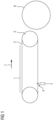
- Fig. 1 The conveyor device in a side view.
- the Figure 1 shows the conveyor device with the tire drum 6 in a side view.
- the conveyor device includes in particular the divided conveyor belt 2 with the connection point 4.
- the conveyor belt 2 is driven with two rollers 3 in the material flow direction 7.
- the connection point 4 on the conveyor belt 2 can be detected with a sensor 5.
- the sensor 5 includes, for example, a metal detector with which a metal in the connection point is detected.
- the metal can be, for example, a metal plate which is arranged at the connection point 4. It is also conceivable that the connection point 4 has metal clips that connect the ends of the split conveyor belt 2 to one another. In this exemplary embodiment it would no longer be necessary to provide the connection point with an additional metal plate.
- the conveyor belt 2 is positioned via servo motors that drive the rollers 3 so that the tire component 1 to be placed does not come into contact with the connection point 4.
- the figure shows that the tire component 1 lies on the top of the conveyor belt 2 and is then conveyed to the tire building drum 6 shown schematically.
- the connection point 4 on the conveyor belt 2 is located on the opposite lower side of the conveyor device. With the conveyor device and the rotating conveyor belt 2, the tire component is placed on the tire building drum 6 shown schematically.
- the tire component can be, for example, a carcass insert, a tire inner liner or bead reinforcements with which a vehicle tire in conjunction with a tire building drum.
Landscapes
- Engineering & Computer Science (AREA)
- Mechanical Engineering (AREA)
- Tyre Moulding (AREA)
Abstract
a) Bereitstellen eines vorkonfektionierten Reifenbauteiles (1),
b) Bereitstellen einer Fördervorrichtung mit einem Förderband (2),
wobei das Förderband (2) mit einem Verbindungsmittel an einer Verbindungsstelle (4) ein geschlossenes Band bildet,
c) Detektieren der Verbindungsstelle (4) am Förderband (2) mit einem Sensor (5),
d) Drehen des Förderbandes (2) in eine Förderposition bei der das Reifenbauteil (1) dergestallt auf das Förderband (2) aufgebracht werden kann, so dass das Reifenbauteil (1) nicht mit der Verbindungsstelle (4) am Förderband (2) in Kontakt tritt,
e) Zuführen des Reifenbauteiles (1) auf die Fördervorrichtung,
wobei das Reifenbauteil (2) auf einen Teilbereich des Förderbandes (2) aufgelegt wird, welches nicht die Verbindungsstelle (4) am Förderband (2) kontaktiert,
f) Zuführen des Reifenbauteiles (1) mit der Fördervorrichtung auf eine Reifenbautrommel (6),
g) Fertigstellen des Fahrzeugreifens mit weiteren Schritten.
Description
- Die Erfindung betrifft ein Verfahren zur Herstellung eines Fahrzeugreifens.
- Es ist bekannt, dass bei der Herstellung von Fahrzeugreifen mit Reifenaufbautrommeln Fördervorrichtungen eingesetzt werden, mit denen Reifenbauteile auf eine Reifenbautrommel aufgelegt werden. Im Normalfall werden diese Fördervorrichtungen mit so genannten Endlosförderbändern betrieben. Der Einsatz von geteilten Förderbändern mit einer Verbindungsstelle hat Nachteile, weil das Probleme beim Auflegen vom Reifenbauteil auf das Förderband mit sich bringen kann. Außerdem ist der Austausch Endlosförderbändern mit einem hohen Zeit- und Arbeitsaufwand verbunden.
- Der Erfindung liegt die Aufgabe zugrunde, ein Verfahren bereitzustellen, mit dem der Einsatz von Fördervorrichtungen bei der Herstellung von Fahrzeugreifen verbessert wird.
- Gelöst wird die Aufgabe gemäß Anspruch 1 dadurch, dass ein Verfahren mit folgenden Schritten eingesetzt wird:
- a) Bereitstellen eines vorkonfektionierten Reifenbauteiles,
- b) Bereitstellen einer Fördervorrichtung mit einem Förderband,
wobei das Förderband mit einem Verbindungsmittel an einer Verbindungsstelle ein geschlossenes Band bildet, - c) Detektieren der Verbindungsstelle am Förderband,
- d) Drehen des Förderbandes in eine Förderposition bei der das Reifenbauteil dergestallt auf das Förderband aufgebracht werden kann, so dass das Reifenbauteil nicht mit der Verbindungsstelle am Förderband in Kontakt tritt,
- e) Zuführen des Reifenbauteiles auf die Fördervorrichtung,
wobei das Reifenbauteil auf einen Teilbereich des Förderbandes aufgelegt wird, welches nicht die Verbindungsstelle am Förderband kontaktiert, - f) Zuführen des Reifenbauteiles mit der Fördervorrichtung auf eine Reifenbautrommel,
- g) Fertigstellen des Fahrzeugreifens mit weiteren Schritten.
- Ein Vorteil der Erfindung ist insbesondere darin zu sehen, dass durch das Verfahren der Einsatz von Fördervorrichtungen bei der Herstellung von Fahrzeugreifen wesentlich verbessert und vereinfacht wird. Mit dem neuen Verfahren können jetzt auch Fördervorrichtungen mit einem geteilten Förderband zum Einsatz kommen. Der Austausch von geteilten Förderbändern mit einer Verbindungsstelle lässt sich wesentlich einfacher vollziehen, als das mit einem Endlosförderband der Fall ist. Dadurch werden u.a. Wartungskosten gespart und die Verfügbarkeit der Reifenherstellungsanlage wesentlich erhöht.
- Das neue Verfahren zeichnet sich insbesondere dadurch aus, dass das Reifenbauteil beim Auflegen auf die Fördervorrichtung nicht mit der Verbindungsstelle am Förderband in Kontakt treten kann. Mit dem Sensor und der Steuerung der Fördervorrichtung wird das Förderband immer so positioniert, dass das Reifenbauteil kontaktlos zur Verbindungsstelle am Förderband aufgelegt werden kann. Bei der Verbindungsstelle am Förderband handelt es sich in der Regel um eine Ausbeulung am Förderband, die die Genauigkeit beim Auflegen des Reifenbauteiles auf die Fördervorrichtung beeinträchtigen kann. Außerdem wird mit dem neuen Verfahren eine voll automatisierte Ausrichtung des Förderbandes ermöglicht.
- In einer vorteilhaften Weiterbildung der Erfindung ist vorgesehen, dass der Sensor einen Metalldetektor zum Ermitteln der Verbindungsstelle umfasst.
- Mit dem Metalldetektor lässt sich die Verbindungsstelle am Förderband einfach und schnell detektieren.
- In einer weiteren vorteilhaften Weiterbildung der Erfindung ist vorgesehen, dass das Verbindungsmittel am Förderband ein Metall umfasst.
- Beispielsweise könnte die Verbindungsstelle mit einem Metallplättchen versehen werden, welches durch den Metalldetektor erkannt werden kann.
- In einer weiteren vorteilhaften Weiterbildung der Erfindung ist vorgesehen, dass das Verbindungsmittel am Förderband in Form von Metallklammern ausgebildet ist.
- Mit den Metallklammern lässt sich eine hochfeste Verbindung für das geteilte Förderband erzielen.
- In einer weiteren vorteilhaften Weiterbildung der Erfindung ist vorgesehen, dass der Sensor einen optischen Sensor zum Ermitteln der Verbindungsstelle umfasst. Mit einem optischen Sensor lässt sich die Verbindungsstelle einfach und mit einer hohen Genauigkeit identifizieren. Der optische Sensor könnte beispielsweise in Form einer Lichtschranke ausgebildet sein, wobei sich an der Verbindungsstelle eine Öffnung befindet, die lichtdurchlässig ist.
- In einer weiteren vorteilhaften Weiterbildung der Erfindung ist vorgesehen, dass mindestens eine Rolle der Fördervorrichtung mit einem Servomotor angetrieben wird,
wobei mit dem Servomotor die relative Position der Verbindungsstelle vom Förderband gesteuert und/oder geregelt wird. - Dadurch kann das Förderband der Fördervorrichtung voll automatisiert in die richtige Position gebracht werden.
- In einer weiteren vorteilhaften Weiterbildung der Erfindung ist vorgesehen, dass das Verbindungsmittel am Förderband in Form einer wieder lösbaren Verbindung ausgebildet ist.
- Dadurch kann das Förderband auf einfache Weise an der Verbindungsstelle wieder geöffnet werden. Das Öffnen des Förderbandes kann beispielsweise bei Wartungsarbeiten hilfreich sein.
- Anhand von Ausführungsbeispielen soll die Erfindung näher erläutert werden. Es zeigt:
Fig. 1 : Die Fördervorrichtung in einer Seitenansicht. - Die
Figur 1 zeigt die Fördervorrichtung mit der Reifentrommel 6 in einer Seitenansicht. Die Fördervorrichtung umfasst insbesondere das geteilte Förderband 2 mit der Verbindungsstelle 4. Das Förderband 2 wird mit zwei Rollen 3 in der Materialflussrichtung 7 angetrieben. Nachdem die Fördervorrichtung mit dem geteilten Förderband 2 ausgestattet worden ist, kann mit einem Sensor 5 die Verbindungsstelle 4 am Förderband 2 detektiert werden. Der Sensor 5 umfasst beispielsweise einen Metalldetektor, mit dem ein Metall in der Verbindungsstelle detektiert wird. Bei dem Metall kann es sich beispielsweise um ein Metallplättchen handeln, welches an der Verbindungsstelle 4 angeordnet wird. Es ist ebenfalls denkbar, dass die Verbindungsstelle 4 Metallklammern aufweist, die die Enden des geteilten Förderbandes 2 miteinander verbinden. Bei diesem Ausführungsbeispiel wäre es nicht mehr notwendig, die Verbindungsstelle mit einem zusätzlichen Metallplättchen zu versehen. Das Förderband 2 wird über Servomotoren, die die Rollen 3 antreiben, so positioniert, dass das aufzulegende Reifenbauteil 1 nicht in Kontakt mit der Verbindungsstelle 4 tritt. - Die Figur zeigt, dass das Reifenbauteil 1 auf der Oberseite des Förderbandes 2 liegt und anschließende zur schematisch dargestellten Reifenbautrommel 6 gefördert wird. Die Verbindungsstelle 4 am Förderband 2 befindet sich auf der gegenüberliegenden unteren Seite der Fördervorrichtung. Mit der Fördervorrichtung und dem drehenden Förderband 2 wird das Reifenbauteil auf die schematisch dargestellte Reifenbautrommel 6 aufgelegt. Bei dem Reifenbauteil kann es sich beispielsweise um eine Karkasseinlage, um einen Reifeninnenliner oder um Wulstverstärker handeln, mit denen ein Fahrzeugreifen in Verbindung mit einer Reifenbautrommel hergestellt wird.
-
- 1
- Reifenbauteil (z.B. Karkasseinlage)
- 2
- Geteiltes Förderband
- 3
- Rolle der Fördervorrichtung
- 4
- Verbindungsstelle vom Förderband
- 5
- Sensor
- 6
- Reifenbautrommel
- 7
- Materialflussrichtung vom Reifenbauteil
Claims (7)
- Verfahren zur Herstellung eines Fahrzeugreifens mit folgenden Schritten:a) Bereitstellen eines vorkonfektionierten Reifenbauteiles (1),b) Bereitstellen einer Fördervorrichtung mit einem Förderband (2),
wobei das Förderband (2) mit einem Verbindungsmittel an einer Verbindungsstelle (4) ein geschlossenes Band bildet,c) Detektieren der Verbindungsstelle (4) am Förderband (2),d) Drehen des Förderbandes (2) in eine Förderposition bei der das Reifenbauteil (1) dergestallt auf das Förderband (2) aufgebracht werden kann, so dass das Reifenbauteil (1) nicht mit der Verbindungsstelle (4) am Förderband (2) in Kontakt tritt,e) Zuführen des Reifenbauteiles (1) auf die Fördervorrichtung,
wobei das Reifenbauteil (2) auf einen Teilbereich des Förderbandes (2) aufgelegt wird, welches nicht die Verbindungsstelle (4) am Förderband (2) kontaktiert,f) Zuführen des Reifenbauteiles (1) mit der Fördervorrichtung auf eine Reifenbautrommel (6),g) Fertigstellen des Fahrzeugreifens mit weiteren Schritten. - Verfahren nach Anspruch 1,
dadurch gekennzeichnet, dass
das Detektieren der Verbindungsstelle (4) am Förderband (2) mit einem Sensor erfolgt, wobei der Sensor (5) einen Metalldetektor zum Ermitteln der Verbindungsstelle (4) umfasst. - Verfahren nach einem der vorhergehenden Ansprüche,
dadurch gekennzeichnet, dass
das Verbindungsmittel (4) am Förderband ein Metall umfasst. - Verfahren nach einem der vorhergehenden Ansprüche,
dadurch gekennzeichnet, dass
das Verbindungsmittel (4) am Förderband in Form von Metallklammern ausgebildet ist. - Verfahren nach einem der vorhergehenden Ansprüche,
dadurch gekennzeichnet, dass
der Sensor (5) einen optischen Sensor zum Ermitteln der Verbindungsstelle (4) umfasst. - Verfahren nach einem der vorhergehenden Ansprüche,
dadurch gekennzeichnet, dassmindestens eine Rolle (3) der Fördervorrichtung mit einem Servomotor angetrieben wird,wobei mit dem Servomotor die relative Position der Verbindungsstelle (4) vom Förderband (2) gesteuert und/oder geregelt wird. - Verfahren nach einem der vorhergehenden Ansprüche,
dadurch gekennzeichnet, dass
das Verbindungsmittel (4) am Förderband (2) in Form einer wieder lösbaren Verbindung ausgebildet ist.
Applications Claiming Priority (1)
| Application Number | Priority Date | Filing Date | Title |
|---|---|---|---|
| DE102022205653.1A DE102022205653A1 (de) | 2022-06-02 | 2022-06-02 | Verfahren zur Herstellung eines Fahrzeugreifens |
Publications (2)
| Publication Number | Publication Date |
|---|---|
| EP4286145A1 true EP4286145A1 (de) | 2023-12-06 |
| EP4286145B1 EP4286145B1 (de) | 2025-01-15 |
Family
ID=86329813
Family Applications (1)
| Application Number | Title | Priority Date | Filing Date |
|---|---|---|---|
| EP23171459.3A Active EP4286145B1 (de) | 2022-06-02 | 2023-05-04 | Verfahren zur herstellung eines fahrzeugreifens |
Country Status (2)
| Country | Link |
|---|---|
| EP (1) | EP4286145B1 (de) |
| DE (1) | DE102022205653A1 (de) |
Citations (5)
| Publication number | Priority date | Publication date | Assignee | Title |
|---|---|---|---|---|
| DE1015214B (de) * | 1953-08-20 | 1957-09-05 | Stahlgruber Gruber & Co Otto | Verfahren zum Verbinden der Enden von Foerderbaendern, Riemen od. dgl. |
| DE202012008090U1 (de) * | 2012-08-24 | 2012-09-14 | Mettler-Toledo Garvens Gmbh | Förderband für eine Transporteinrichtung |
| WO2016103078A1 (en) * | 2014-12-24 | 2016-06-30 | Pirelli Tyre S.P.A. | Tyre building plant and method for supplying an elongated element to a forming drum in a tyre building plant |
| EP3141382A1 (de) * | 2014-05-09 | 2017-03-15 | The Yokohama Rubber Co., Ltd. | Verfahren und vorrichtung zum giessen eines zylinderförmigen elements |
| EP3552811A1 (de) * | 2018-04-13 | 2019-10-16 | Continental Reifen Deutschland GmbH | Verfahren zur herstellung eines fahrzeugreifens |
-
2022
- 2022-06-02 DE DE102022205653.1A patent/DE102022205653A1/de active Pending
-
2023
- 2023-05-04 EP EP23171459.3A patent/EP4286145B1/de active Active
Patent Citations (5)
| Publication number | Priority date | Publication date | Assignee | Title |
|---|---|---|---|---|
| DE1015214B (de) * | 1953-08-20 | 1957-09-05 | Stahlgruber Gruber & Co Otto | Verfahren zum Verbinden der Enden von Foerderbaendern, Riemen od. dgl. |
| DE202012008090U1 (de) * | 2012-08-24 | 2012-09-14 | Mettler-Toledo Garvens Gmbh | Förderband für eine Transporteinrichtung |
| EP3141382A1 (de) * | 2014-05-09 | 2017-03-15 | The Yokohama Rubber Co., Ltd. | Verfahren und vorrichtung zum giessen eines zylinderförmigen elements |
| WO2016103078A1 (en) * | 2014-12-24 | 2016-06-30 | Pirelli Tyre S.P.A. | Tyre building plant and method for supplying an elongated element to a forming drum in a tyre building plant |
| EP3552811A1 (de) * | 2018-04-13 | 2019-10-16 | Continental Reifen Deutschland GmbH | Verfahren zur herstellung eines fahrzeugreifens |
Also Published As
| Publication number | Publication date |
|---|---|
| DE102022205653A1 (de) | 2023-12-07 |
| EP4286145B1 (de) | 2025-01-15 |
Similar Documents
| Publication | Publication Date | Title |
|---|---|---|
| DE19641509C2 (de) | Verfahren zum Transport eines Gürtelaufbaustreifens zum Aufbau eines Gürtels für einen Fahrzeugluftreifen | |
| EP2046566B1 (de) | Zubringereinrichtung | |
| DE102016221271B4 (de) | Verfahren und Vorrichtung zum Anbringen einer flexiblen Dichtung an dem Umfang eines Bauteils | |
| AT517335B1 (de) | Verfahren und Vorrichtung zum Herstellen eines Metallbands mit weitgehend parallelen Bandkanten | |
| EP3248912A1 (de) | Vorrichtung und verfahren zum wenden von profilen | |
| DE69126025T2 (de) | Vorrichtung zum anbringen von reifenbestandteilen | |
| DE102016124384B4 (de) | Verfahren und Vorrichtung zum Fügen von Werkstücken | |
| EP4286145B1 (de) | Verfahren zur herstellung eines fahrzeugreifens | |
| DE102015219877B4 (de) | Verfahren und Vorrichtung zum Richten eines Metallbandes | |
| EP0698479A1 (de) | Spleissmaschine | |
| DE1752208C3 (de) | Vorrichtung zum Zuführen von lagerichtig ausgerichteten Felgenringrohlingen zu einer Schweißvorrichtung | |
| EP1572389B1 (de) | Umlenkvorrichtung einer haspelanlage zum aufhaspeln von bändern | |
| DE102012102222A1 (de) | Verfahren für eine Positionskorrektur der Spitzen eines Reifengürtels beim Aufwickeln auf einer Reifenaufbautrommel | |
| EP3495131B1 (de) | Vorrichtung und verfahren zum aufwickeln eines zur herstellung eines gürtels eines fahrzeugluftreifens geeigneten gürtelaufbaustreifens auf eine gürtelaufbautrommel | |
| EP3741547B1 (de) | Verfahren und vorrichtung zum ausrichten und aufrichten eines fahrzeugreifens im zuge der automatisierten einbringung eines bauteiles in den fahrzeugreifen | |
| EP2099574B1 (de) | Steuerverfahren für ein walzgerüst zum walzen eines bandes | |
| DE102008039738B4 (de) | Verfahren für eine Positionskorrektur einer Spitze eines Reifenaufbauteiles beim Übergang von einem ersten zu einem zweiten Förderband | |
| EP3943429B1 (de) | Verfahren zum automatisierten wechsel einer materialkassette bei der herstellung von fahrzeugreifen | |
| EP2756945B1 (de) | Verfahren zur Herstellung von Fahrzeugreifen mit einer Reifenaufbautrommel | |
| DE102023200906A1 (de) | Verfahren zur Herstellung eines Fahrzeugreifens | |
| DE3913240A1 (de) | Vorrichtung zum ankleben eines metallcordstreifens | |
| DE19513610C2 (de) | Verfahren und Vorrichtung zur Förderung von Werkstücken | |
| EP1899145A1 (de) | Verfahren und vorrichtung einsetzbar im automatisiert ablaufenden aufbau eines fahrzeugluftreifens | |
| DE102008027968A1 (de) | Walzmaschine und Verfahren zum Wechseln der Walzen oder der Walzenwerkzeuge der Walzmaschine | |
| DE102007001151A1 (de) | Vorrichtung zum Schneiden und Spleissen von Bandabschnitten eines klebrigen Kordbandes |
Legal Events
| Date | Code | Title | Description |
|---|---|---|---|
| PUAI | Public reference made under article 153(3) epc to a published international application that has entered the european phase |
Free format text: ORIGINAL CODE: 0009012 |
|
| STAA | Information on the status of an ep patent application or granted ep patent |
Free format text: STATUS: THE APPLICATION HAS BEEN PUBLISHED |
|
| AK | Designated contracting states |
Kind code of ref document: A1 Designated state(s): AL AT BE BG CH CY CZ DE DK EE ES FI FR GB GR HR HU IE IS IT LI LT LU LV MC ME MK MT NL NO PL PT RO RS SE SI SK SM TR |
|
| RAP3 | Party data changed (applicant data changed or rights of an application transferred) |
Owner name: CONTINENTAL REIFEN DEUTSCHLAND GMBH |
|
| STAA | Information on the status of an ep patent application or granted ep patent |
Free format text: STATUS: REQUEST FOR EXAMINATION WAS MADE |
|
| 17P | Request for examination filed |
Effective date: 20240606 |
|
| RBV | Designated contracting states (corrected) |
Designated state(s): AL AT BE BG CH CY CZ DE DK EE ES FI FR GB GR HR HU IE IS IT LI LT LU LV MC ME MK MT NL NO PL PT RO RS SE SI SK SM TR |
|
| GRAP | Despatch of communication of intention to grant a patent |
Free format text: ORIGINAL CODE: EPIDOSNIGR1 |
|
| STAA | Information on the status of an ep patent application or granted ep patent |
Free format text: STATUS: GRANT OF PATENT IS INTENDED |
|
| RIC1 | Information provided on ipc code assigned before grant |
Ipc: B65G 43/00 20060101ALI20240926BHEP Ipc: B29C 31/00 20060101ALI20240926BHEP Ipc: B29D 30/30 20060101ALI20240926BHEP Ipc: B29D 30/00 20060101AFI20240926BHEP |
|
| INTG | Intention to grant announced |
Effective date: 20241024 |
|
| GRAS | Grant fee paid |
Free format text: ORIGINAL CODE: EPIDOSNIGR3 |
|
| GRAA | (expected) grant |
Free format text: ORIGINAL CODE: 0009210 |
|
| STAA | Information on the status of an ep patent application or granted ep patent |
Free format text: STATUS: THE PATENT HAS BEEN GRANTED |
|
| P01 | Opt-out of the competence of the unified patent court (upc) registered |
Free format text: CASE NUMBER: APP_63677/2024 Effective date: 20241129 |
|
| AK | Designated contracting states |
Kind code of ref document: B1 Designated state(s): AL AT BE BG CH CY CZ DE DK EE ES FI FR GB GR HR HU IE IS IT LI LT LU LV MC ME MK MT NL NO PL PT RO RS SE SI SK SM TR |
|
| REG | Reference to a national code |
Ref country code: CH Ref legal event code: EP Ref country code: GB Ref legal event code: FG4D Free format text: NOT ENGLISH |
|
| REG | Reference to a national code |
Ref country code: DE Ref legal event code: R096 Ref document number: 502023000460 Country of ref document: DE |
|
| REG | Reference to a national code |
Ref country code: IE Ref legal event code: FG4D Free format text: LANGUAGE OF EP DOCUMENT: GERMAN |
|
| REG | Reference to a national code |
Ref country code: NL Ref legal event code: MP Effective date: 20250115 |
|
| PG25 | Lapsed in a contracting state [announced via postgrant information from national office to epo] |
Ref country code: NL Free format text: LAPSE BECAUSE OF FAILURE TO SUBMIT A TRANSLATION OF THE DESCRIPTION OR TO PAY THE FEE WITHIN THE PRESCRIBED TIME-LIMIT Effective date: 20250115 |
|
| PG25 | Lapsed in a contracting state [announced via postgrant information from national office to epo] |
Ref country code: RS Free format text: LAPSE BECAUSE OF FAILURE TO SUBMIT A TRANSLATION OF THE DESCRIPTION OR TO PAY THE FEE WITHIN THE PRESCRIBED TIME-LIMIT Effective date: 20250415 |
|
| PG25 | Lapsed in a contracting state [announced via postgrant information from national office to epo] |
Ref country code: FI Free format text: LAPSE BECAUSE OF FAILURE TO SUBMIT A TRANSLATION OF THE DESCRIPTION OR TO PAY THE FEE WITHIN THE PRESCRIBED TIME-LIMIT Effective date: 20250115 |
|
| PG25 | Lapsed in a contracting state [announced via postgrant information from national office to epo] |
Ref country code: PL Free format text: LAPSE BECAUSE OF FAILURE TO SUBMIT A TRANSLATION OF THE DESCRIPTION OR TO PAY THE FEE WITHIN THE PRESCRIBED TIME-LIMIT Effective date: 20250115 |
|
| PGFP | Annual fee paid to national office [announced via postgrant information from national office to epo] |
Ref country code: DE Payment date: 20250531 Year of fee payment: 3 |
|
| PG25 | Lapsed in a contracting state [announced via postgrant information from national office to epo] |
Ref country code: ES Free format text: LAPSE BECAUSE OF FAILURE TO SUBMIT A TRANSLATION OF THE DESCRIPTION OR TO PAY THE FEE WITHIN THE PRESCRIBED TIME-LIMIT Effective date: 20250115 |
|
| REG | Reference to a national code |
Ref country code: LT Ref legal event code: MG9D |
|
| PG25 | Lapsed in a contracting state [announced via postgrant information from national office to epo] |
Ref country code: NO Free format text: LAPSE BECAUSE OF FAILURE TO SUBMIT A TRANSLATION OF THE DESCRIPTION OR TO PAY THE FEE WITHIN THE PRESCRIBED TIME-LIMIT Effective date: 20250415 Ref country code: IS Free format text: LAPSE BECAUSE OF FAILURE TO SUBMIT A TRANSLATION OF THE DESCRIPTION OR TO PAY THE FEE WITHIN THE PRESCRIBED TIME-LIMIT Effective date: 20250515 |
|
| PG25 | Lapsed in a contracting state [announced via postgrant information from national office to epo] |
Ref country code: HR Free format text: LAPSE BECAUSE OF FAILURE TO SUBMIT A TRANSLATION OF THE DESCRIPTION OR TO PAY THE FEE WITHIN THE PRESCRIBED TIME-LIMIT Effective date: 20250115 |
|
| PG25 | Lapsed in a contracting state [announced via postgrant information from national office to epo] |
Ref country code: PT Free format text: LAPSE BECAUSE OF FAILURE TO SUBMIT A TRANSLATION OF THE DESCRIPTION OR TO PAY THE FEE WITHIN THE PRESCRIBED TIME-LIMIT Effective date: 20250515 Ref country code: LV Free format text: LAPSE BECAUSE OF FAILURE TO SUBMIT A TRANSLATION OF THE DESCRIPTION OR TO PAY THE FEE WITHIN THE PRESCRIBED TIME-LIMIT Effective date: 20250115 |
|
| PGFP | Annual fee paid to national office [announced via postgrant information from national office to epo] |
Ref country code: FR Payment date: 20250528 Year of fee payment: 3 |
|
| PG25 | Lapsed in a contracting state [announced via postgrant information from national office to epo] |
Ref country code: GR Free format text: LAPSE BECAUSE OF FAILURE TO SUBMIT A TRANSLATION OF THE DESCRIPTION OR TO PAY THE FEE WITHIN THE PRESCRIBED TIME-LIMIT Effective date: 20250416 Ref country code: BG Free format text: LAPSE BECAUSE OF FAILURE TO SUBMIT A TRANSLATION OF THE DESCRIPTION OR TO PAY THE FEE WITHIN THE PRESCRIBED TIME-LIMIT Effective date: 20250115 |
|
| PGFP | Annual fee paid to national office [announced via postgrant information from national office to epo] |
Ref country code: AT Payment date: 20250721 Year of fee payment: 3 |
|
| PG25 | Lapsed in a contracting state [announced via postgrant information from national office to epo] |
Ref country code: SE Free format text: LAPSE BECAUSE OF FAILURE TO SUBMIT A TRANSLATION OF THE DESCRIPTION OR TO PAY THE FEE WITHIN THE PRESCRIBED TIME-LIMIT Effective date: 20250115 |
|
| PG25 | Lapsed in a contracting state [announced via postgrant information from national office to epo] |
Ref country code: SM Free format text: LAPSE BECAUSE OF FAILURE TO SUBMIT A TRANSLATION OF THE DESCRIPTION OR TO PAY THE FEE WITHIN THE PRESCRIBED TIME-LIMIT Effective date: 20250115 |
|
| PG25 | Lapsed in a contracting state [announced via postgrant information from national office to epo] |
Ref country code: DK Free format text: LAPSE BECAUSE OF FAILURE TO SUBMIT A TRANSLATION OF THE DESCRIPTION OR TO PAY THE FEE WITHIN THE PRESCRIBED TIME-LIMIT Effective date: 20250115 |
|
| PG25 | Lapsed in a contracting state [announced via postgrant information from national office to epo] |
Ref country code: IT Free format text: LAPSE BECAUSE OF FAILURE TO SUBMIT A TRANSLATION OF THE DESCRIPTION OR TO PAY THE FEE WITHIN THE PRESCRIBED TIME-LIMIT Effective date: 20250115 |
|
| REG | Reference to a national code |
Ref country code: DE Ref legal event code: R097 Ref document number: 502023000460 Country of ref document: DE |
|
| PG25 | Lapsed in a contracting state [announced via postgrant information from national office to epo] |
Ref country code: EE Free format text: LAPSE BECAUSE OF FAILURE TO SUBMIT A TRANSLATION OF THE DESCRIPTION OR TO PAY THE FEE WITHIN THE PRESCRIBED TIME-LIMIT Effective date: 20250115 Ref country code: CZ Free format text: LAPSE BECAUSE OF FAILURE TO SUBMIT A TRANSLATION OF THE DESCRIPTION OR TO PAY THE FEE WITHIN THE PRESCRIBED TIME-LIMIT Effective date: 20250115 |
|
| PG25 | Lapsed in a contracting state [announced via postgrant information from national office to epo] |
Ref country code: RO Free format text: LAPSE BECAUSE OF FAILURE TO SUBMIT A TRANSLATION OF THE DESCRIPTION OR TO PAY THE FEE WITHIN THE PRESCRIBED TIME-LIMIT Effective date: 20250115 |
|
| PG25 | Lapsed in a contracting state [announced via postgrant information from national office to epo] |
Ref country code: SK Free format text: LAPSE BECAUSE OF FAILURE TO SUBMIT A TRANSLATION OF THE DESCRIPTION OR TO PAY THE FEE WITHIN THE PRESCRIBED TIME-LIMIT Effective date: 20250115 |
|
| PLBE | No opposition filed within time limit |
Free format text: ORIGINAL CODE: 0009261 |
|
| STAA | Information on the status of an ep patent application or granted ep patent |
Free format text: STATUS: NO OPPOSITION FILED WITHIN TIME LIMIT |
|
| 26N | No opposition filed |
Effective date: 20251016 |
|
| PG25 | Lapsed in a contracting state [announced via postgrant information from national office to epo] |
Ref country code: LU Free format text: LAPSE BECAUSE OF NON-PAYMENT OF DUE FEES Effective date: 20250504 |
|
| REG | Reference to a national code |
Ref country code: BE Ref legal event code: MM Effective date: 20250531 |
|
| PG25 | Lapsed in a contracting state [announced via postgrant information from national office to epo] |
Ref country code: MC Free format text: LAPSE BECAUSE OF FAILURE TO SUBMIT A TRANSLATION OF THE DESCRIPTION OR TO PAY THE FEE WITHIN THE PRESCRIBED TIME-LIMIT Effective date: 20250115 |
|
| PG25 | Lapsed in a contracting state [announced via postgrant information from national office to epo] |
Ref country code: IE Free format text: LAPSE BECAUSE OF NON-PAYMENT OF DUE FEES Effective date: 20250504 |
|
| PG25 | Lapsed in a contracting state [announced via postgrant information from national office to epo] |
Ref country code: BE Free format text: LAPSE BECAUSE OF NON-PAYMENT OF DUE FEES Effective date: 20250531 |