EP4286076B1 - Verfahren zur herstellung eines porösen metallkörpers - Google Patents
Verfahren zur herstellung eines porösen metallkörpers Download PDFInfo
- Publication number
- EP4286076B1 EP4286076B1 EP21923115.6A EP21923115A EP4286076B1 EP 4286076 B1 EP4286076 B1 EP 4286076B1 EP 21923115 A EP21923115 A EP 21923115A EP 4286076 B1 EP4286076 B1 EP 4286076B1
- Authority
- EP
- European Patent Office
- Prior art keywords
- molding plate
- thickness
- porous metal
- metal body
- metal powder
- Prior art date
- Legal status (The legal status is an assumption and is not a legal conclusion. Google has not performed a legal analysis and makes no representation as to the accuracy of the status listed.)
- Active
Links
Images

Classifications
-
- B—PERFORMING OPERATIONS; TRANSPORTING
- B22—CASTING; POWDER METALLURGY
- B22F—WORKING METALLIC POWDER; MANUFACTURE OF ARTICLES FROM METALLIC POWDER; MAKING METALLIC POWDER; APPARATUS OR DEVICES SPECIALLY ADAPTED FOR METALLIC POWDER
- B22F3/00—Manufacture of workpieces or articles from metallic powder characterised by the manner of compacting or sintering; Apparatus specially adapted therefor ; Presses and furnaces
- B22F3/10—Sintering only
- B22F3/11—Making porous workpieces or articles
-
- B—PERFORMING OPERATIONS; TRANSPORTING
- B22—CASTING; POWDER METALLURGY
- B22F—WORKING METALLIC POWDER; MANUFACTURE OF ARTICLES FROM METALLIC POWDER; MAKING METALLIC POWDER; APPARATUS OR DEVICES SPECIALLY ADAPTED FOR METALLIC POWDER
- B22F1/00—Metallic powder; Treatment of metallic powder, e.g. to facilitate working or to improve properties
- B22F1/12—Metallic powder containing non-metallic particles
-
- B—PERFORMING OPERATIONS; TRANSPORTING
- B22—CASTING; POWDER METALLURGY
- B22F—WORKING METALLIC POWDER; MANUFACTURE OF ARTICLES FROM METALLIC POWDER; MAKING METALLIC POWDER; APPARATUS OR DEVICES SPECIALLY ADAPTED FOR METALLIC POWDER
- B22F3/00—Manufacture of workpieces or articles from metallic powder characterised by the manner of compacting or sintering; Apparatus specially adapted therefor ; Presses and furnaces
- B22F3/10—Sintering only
- B22F3/1003—Use of special medium during sintering, e.g. sintering aid
- B22F3/1007—Atmosphere
-
- B—PERFORMING OPERATIONS; TRANSPORTING
- B22—CASTING; POWDER METALLURGY
- B22F—WORKING METALLIC POWDER; MANUFACTURE OF ARTICLES FROM METALLIC POWDER; MAKING METALLIC POWDER; APPARATUS OR DEVICES SPECIALLY ADAPTED FOR METALLIC POWDER
- B22F3/00—Manufacture of workpieces or articles from metallic powder characterised by the manner of compacting or sintering; Apparatus specially adapted therefor ; Presses and furnaces
- B22F3/10—Sintering only
- B22F3/11—Making porous workpieces or articles
- B22F3/1121—Making porous workpieces or articles by using decomposable, meltable or sublimatable fillers
- B22F3/1125—Making porous workpieces or articles by using decomposable, meltable or sublimatable fillers involving a foaming process
-
- B—PERFORMING OPERATIONS; TRANSPORTING
- B22—CASTING; POWDER METALLURGY
- B22F—WORKING METALLIC POWDER; MANUFACTURE OF ARTICLES FROM METALLIC POWDER; MAKING METALLIC POWDER; APPARATUS OR DEVICES SPECIALLY ADAPTED FOR METALLIC POWDER
- B22F7/00—Manufacture of composite layers, workpieces, or articles, comprising metallic powder, by sintering the powder, with or without compacting wherein at least one part is obtained by sintering or compression
- B22F7/002—Manufacture of composite layers, workpieces, or articles, comprising metallic powder, by sintering the powder, with or without compacting wherein at least one part is obtained by sintering or compression of porous nature
-
- B—PERFORMING OPERATIONS; TRANSPORTING
- B22—CASTING; POWDER METALLURGY
- B22F—WORKING METALLIC POWDER; MANUFACTURE OF ARTICLES FROM METALLIC POWDER; MAKING METALLIC POWDER; APPARATUS OR DEVICES SPECIALLY ADAPTED FOR METALLIC POWDER
- B22F9/00—Making metallic powder or suspensions thereof
- B22F9/02—Making metallic powder or suspensions thereof using physical processes
- B22F9/06—Making metallic powder or suspensions thereof using physical processes starting from liquid material
-
- B—PERFORMING OPERATIONS; TRANSPORTING
- B33—ADDITIVE MANUFACTURING TECHNOLOGY
- B33Y—ADDITIVE MANUFACTURING, i.e. MANUFACTURING OF THREE-DIMENSIONAL [3D] OBJECTS BY ADDITIVE DEPOSITION, ADDITIVE AGGLOMERATION OR ADDITIVE LAYERING, e.g. BY 3D PRINTING, STEREOLITHOGRAPHY OR SELECTIVE LASER SINTERING
- B33Y10/00—Processes of additive manufacturing
-
- B—PERFORMING OPERATIONS; TRANSPORTING
- B22—CASTING; POWDER METALLURGY
- B22F—WORKING METALLIC POWDER; MANUFACTURE OF ARTICLES FROM METALLIC POWDER; MAKING METALLIC POWDER; APPARATUS OR DEVICES SPECIALLY ADAPTED FOR METALLIC POWDER
- B22F3/00—Manufacture of workpieces or articles from metallic powder characterised by the manner of compacting or sintering; Apparatus specially adapted therefor ; Presses and furnaces
- B22F3/10—Sintering only
- B22F2003/1042—Sintering only with support for articles to be sintered
-
- B—PERFORMING OPERATIONS; TRANSPORTING
- B22—CASTING; POWDER METALLURGY
- B22F—WORKING METALLIC POWDER; MANUFACTURE OF ARTICLES FROM METALLIC POWDER; MAKING METALLIC POWDER; APPARATUS OR DEVICES SPECIALLY ADAPTED FOR METALLIC POWDER
- B22F9/00—Making metallic powder or suspensions thereof
- B22F9/02—Making metallic powder or suspensions thereof using physical processes
- B22F9/06—Making metallic powder or suspensions thereof using physical processes starting from liquid material
- B22F2009/065—Melting inside a liquid, e.g. making spherical balls
-
- B—PERFORMING OPERATIONS; TRANSPORTING
- B22—CASTING; POWDER METALLURGY
- B22F—WORKING METALLIC POWDER; MANUFACTURE OF ARTICLES FROM METALLIC POWDER; MAKING METALLIC POWDER; APPARATUS OR DEVICES SPECIALLY ADAPTED FOR METALLIC POWDER
- B22F2201/00—Treatment under specific atmosphere
- B22F2201/10—Inert gases
-
- B—PERFORMING OPERATIONS; TRANSPORTING
- B22—CASTING; POWDER METALLURGY
- B22F—WORKING METALLIC POWDER; MANUFACTURE OF ARTICLES FROM METALLIC POWDER; MAKING METALLIC POWDER; APPARATUS OR DEVICES SPECIALLY ADAPTED FOR METALLIC POWDER
- B22F2301/00—Metallic composition of the powder or its coating
- B22F2301/20—Refractory metals
- B22F2301/205—Titanium, zirconium or hafnium
-
- B—PERFORMING OPERATIONS; TRANSPORTING
- B22—CASTING; POWDER METALLURGY
- B22F—WORKING METALLIC POWDER; MANUFACTURE OF ARTICLES FROM METALLIC POWDER; MAKING METALLIC POWDER; APPARATUS OR DEVICES SPECIALLY ADAPTED FOR METALLIC POWDER
- B22F2998/00—Supplementary information concerning processes or compositions relating to powder metallurgy
- B22F2998/10—Processes characterised by the sequence of their steps
-
- B—PERFORMING OPERATIONS; TRANSPORTING
- B22—CASTING; POWDER METALLURGY
- B22F—WORKING METALLIC POWDER; MANUFACTURE OF ARTICLES FROM METALLIC POWDER; MAKING METALLIC POWDER; APPARATUS OR DEVICES SPECIALLY ADAPTED FOR METALLIC POWDER
- B22F5/00—Manufacture of workpieces or articles from metallic powder characterised by the special shape of the product
- B22F5/006—Manufacture of workpieces or articles from metallic powder characterised by the special shape of the product of flat products, e.g. sheets
Definitions
- the present invention relates to a method for manufacturing a porous metal body
- Titanium is known to be a material having excellent corrosion resistance due to the formation of a passivation film on its surface. It is expected that, utilizing such high corrosion resistance, titanium or a titanium alloy will be used, for example, as a porous conductive material that is used in an environment where it can be corroded and requires the necessary air permeability or liquid permeability. Also, in view of the price, it is considerable to adopt a porous material such as stainless steel.
- Patent Literature 1 discloses: "A porous titanium-based sintered body, wherein it has a porosity of 50 to 75%, an average pore size of 23 to 45 ⁇ m, a specific surface area of 0.020 to 0.065 m 2 /g and a bending strength of 22 MPa or more".
- a sheet-shaped porous metal body is manufactured by filling a quartz mold with titanium-based powder under dry and non-pressurized conditions, and leveling the titanium-based powder overflowing above an upper end of the mold, and then sintering the titanium-based powder in a heating furnace while filling the mold with the titanium-based powder.
- an object of the present invention is to provide a method for manufacturing a porous metal body, which can manufacture a porous metal body with a suppressed variation in thickness in spite of multiple use of a molding plate having a relatively thin thickness.
- a good porous metal body can be manufactured by adjusting a thickness of a deposited layer formed by depositing metal powder on the molding plate while flattening the surface of the molding plate, without flattening the surface of the molding plate during sintering.
- the inventors have also found that such measures can be taken by using a molding plate made of carbon.
- the present invention provides a method for manufacturing a porous metal body according to claim 1.
- the sintering step comprises sintering the metal powder at a temperature of 800°C or more.
- the sintering step comprises placing 30 or more of the molding plates in a heating furnace, and sintering the metal powder on each of the molding plates in the heating furnace.
- the present invention is not limited to embodiments described below.
- various inventions can be formed by appropriately combining a plurality of components disclosed in each embodiment.
- the invention may be formed by omitting some components from all the components shown in the embodiments.
- some members are schematically shown in order to facilitate understanding of the embodiments included in the invention, and illustrated sizes, positional relationships, and the like, may not necessarily be accurate.
- the method for manufacturing a porous metal body according to the present invention carries out a plurality of steps including a depositing step and a sintering step. In one embodiment, at least one step of the plurality of steps further includes a thickness adjusting step between the depositing step and the sintering step.
- the plurality of steps can manufacture porous metal bodies having substantially the same characteristic even if the same molding plate is used. It should be noted that the steps may include optional steps in addition to each of the above steps.
- the metal powder is deposited in a dry process onto a molding plate made of carbon.
- the metal powder may be deposited onto the molding plate without flattening the surface of the molding plate, or the metal powder may be deposited onto the molding plate while flattening the surface of the molding plate. That is, in order to manufacture a porous metal body with a decreased variation in thickness, it is important to adjust a thickness of a deposited layer of the metal powder, obtained by depositing the metal powder on the molding plate, while flattening the surface of the molding plate, in a thickness adjusting step as described later.
- the metal powder may be deposited onto the molding plate.
- the downward pressing is continued until the thickness adjustment of the deposited layer is completed.
- Specific pressing means include a vise and the like. A part of the molding plate may be sandwiched by the vise or the like and pressed downward so that the surface of the molding plate becomes flat. Positions where the plate is sandwiched by the vise or the like employ a part of the edge portion of the surface of the molding plate.
- At least a part of a pair of opposing long side or short side edge portions of a rectangular molding plate in a plane view is preferably sandwiched by the vise or the like together with a pedestal member having a horizontal surface and the molding plate on the horizontal surface.
- a pedestal member having a horizontal surface and the molding plate on the horizontal surface For a circular or elliptical molding plate in a plane view, at least a part of the edge portions is preferably sandwiched by the vise or the like together with the pedestal member having a horizontal surface and the molding plate on the horizontal surface.
- the sandwiching positions may be opposed to each other via an axis of symmetry passing through the center of the surface of the molding plate or the center of gravity in a plane view, for example such that two corners 104 of a molding plate 100 may be sandwiched by the vise and pressed downward (see Fig. 3 ).
- the metal powder may be deposited onto the molding plate without flattening the surface of the molding plate.
- the thickness adjusting step described later the thickness of the deposited layer formed by depositing the metal powder onto the molding plate can be adjusted while flattening the surface of the molding plate using the vise or the like.
- the thickness of the molding plate is 30 mm or less from the viewpoint of production efficiency. From the viewpoint of increasing the number of use of the molding plate, the lower limit of the thickness of the molding plate is 3 mm or more.
- the thickness of the molding plate may be in the range of 3 mm to 15 mm, or in the range of 3 mm to 8 mm.
- the surface area of the molding plate may be 36 cm 2 or more (for example, 6 cm x 6 cm or more) as the lower limit.
- the upper limit of the surface area of the molding plate is typically 15000 cm 2 or less, or even 5000 cm 2 or less.
- the molding plate having a surface area of 4500 cm 2 e.g., 90 cm ⁇ 50 cm can also be employed.
- the area of the deposition region where the metal powder is to be deposited on the surface of the molding plate is not particularly limited as long as the area required for pressing the molding plate downward is ensured on the surface. Therefore, the area of the deposition area on which the metal powder is to be deposited is smaller than the area of the surface of the molding plate.
- the area of the deposition region can be appropriately adjusted depending on the dimensions of the porous metal body.
- the shape of the metal powder is not particularly limited.
- pulverized powder such as HDH powder may be used, or atomized powder having a high degree of circularity in plane view may be used.
- the particle size of the metal powder can be appropriately selected, and for example, such that D50 is preferably 10 to 150 ⁇ m, and more preferably 10 to 80 ⁇ m. Also, the D50 of the metal powder is preferably 10 to 45 ⁇ m.
- the term "D50" refers to a particle size where a cumulative amount counted from the smaller particle size side is 50% of the entire powder sample in a distribution on a volume basis, measured using a laser diffraction/scattering particle size distribution meter for the powder sample. The same is true for a particle size D50 of the metal powder, which will be described later.
- the thickness of the deposited layer of the metal powder deposited on the molding plate is adjusted.
- the thickness adjustment is typically performed in the production of the sheet-shaped porous metal body.
- the molding plate to be used does not have a flat surface, the thickness of the deposited layer of the metal powder on the molding plate is adjusted while flattening the surface of the molding plate, thereby reducing a variation in thickness of the porous metal body manufactured.
- the repeated use of the molding plate may lead to a loss of flatness of the surface. Therefore, for example, after the second or later use of the molding plate, the operation of flatting the surface of the molding plate may be performed taking the shape of the molding plate into account.
- the operation of flattening the surface of the molding plate may be performed as described in the depositing step. Further, the operation of flattening the surface of the molding plate may be performed each time the thickness adjusting step is performed.
- the thickness of the deposited layer of the metal powder deposited on the molding plate may be performed by, for example, leveling an upper surface of the metal powder using an applicator to have a sheet shape, for the deposited layer of the metal powder on the molding plate. In this case, any excess metal powder can be removed from the surface of the molding plate. Therefore, in one embodiment, the thickness adjusting step reduces a variation in thickness of the porous metal body obtained in the sintering step.
- the process for adjusting the thickness includes, for example, the applicator method as described above.
- the applicator may be provided with a pair of sleeves arranged to face each other and a blade such as a metal blade arranged between the pair of sleeves, and the width setting and clearance (thickness) may be adjusted as needed.
- a commercially available product may be used as required.
- the molding plate having the deposited layer of the metal powder is placed on the horizontal surface of the pedestal member, and at least a part of the edge portions of the surface of the molding plate and the pedestal member are sandwiched by the vise so that the surface of the molding plate is flat, and a part of the edge portions is pressed downward.
- the pair of sleeves of the applicator are then placed over the surface of the molding plate to adjust the width of the applicator. Subsequently, a certain clearance is formed between the metal blade and the surface of the molding plate. Then, the thickness of the deposited layer of the metal powder is adjusted by the metal blade so to be uniform while moving the pair of sleeves of the applicator with respect to the surface of the molding plate.
- the thickness of the deposited layer of the metal powder can be adjusted with reference to the above descriptions. In other words, it is possible to address the shape of the molding surface by appropriately combining the setting of the applicator with the moving direction.
- the sintering step is performed to sinter the metal powder on the molding plate.
- a porous metal body is obtained as a sintered body.
- the thickness of the deposited layer of the metal powder has been adjusted in the thickness adjusting step as described above.
- the sintering is preferably carried out using a heating furnace in order to facilitate atmosphere control of the sintering process.
- the pressing onto the surface of the molding plate is typically released after the thickness adjusting step is completed. Therefore, the molding plate and the deposited layer of the metal powder formed on the molding plate are stored in the heating furnace.
- the variation change rate ⁇ does not reach a desired value, i.e., if the variation in the thickness of the manufactured porous metal body does not fall within the desired range, nevertheless the thickness of the deposited layer of the metal powder was adjusted while flattening the surface of the molding plate using the vise or the like in the thickness adjusting step, it is preferable to replace the molding plate being used.
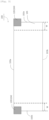
- Example 1 a molding plate made of carbon (in a flat plate shape: 110 mm in vertical (L1) x 330 mm in horizontal (L2) x 25 mm in thickness) as shown in Fig. 1 was prepared. Subsequently, HDH titanium powder 110 (having a titanium purity of 99.9% by mass or more, and D50 of 13 ⁇ m) was deposited onto a surface 105 of a molding plate 100 in a dry process. In this case, the HDH titanium powder 110 was not deposited in the range from both edges 102a, 102b parallel to each other in the vertical direction to a position having a width W of 40 mm.
- the thickness of the deposited layer of the HDH titanium powder 110 deposited on the molding plate 100 was adjusted by an applicator (commercially available product) with a film thickness adjustment function in order to suppress the variation in the thickness.
- the molding plate 100 on which the HDH titanium powder 110 was deposited was placed in an electric heating furnace, the interior of the electric heating furnace was brought to an inert atmosphere, and sintering was performed at a furnace temperature of 1000°C for a heating retention time of 3 hours. After cooling, the sheet-shaped porous metal body was peeled off from the molding plate 100. As a result of measuring the average thickness of the resulting sheet-shaped porous metal body according to the procedure as described above, the average thickness was 0.2 mm.
- the manufacturing process of the sheet-shaped porous metal body was repeated seven times according to the above operation.
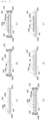
- the HDH titanium powder 110 was sintered according to the procedure as shown in Figs. 2(A) to 2(F) . It should be noted that the illustrations in Figs. 2(A) to 2(F) are schematic, and the illustrated sizes and the like may not necessarily be accurate.
- the molding plate 100 was placed on a horizontal surface 125a of a pedestal member 125. Subsequently, as shown in Fig.
- the applicator was moved along the vertical direction from the side of the edge 103a sandwiched by the vise to the side of the edge 103b paired with the edge 103a to perform the adjustment such that the thickness of the deposited layer of HDH titanium powder 110 was uniform.
- the vise 120 was removed from the molding plate 100 and the pedestal member 125.
- the molding plate 100 was then placed in an electric heating furnace, and the interior of the electric heating furnace was brought to an inert atmosphere, and the sintering was performed at a furnace temperature of 1000°C for a heating retention time of 3 hours.
- Fig. 2(D) the applicator was moved along the vertical direction from the side of the edge 103a sandwiched by the vise to the side of the edge 103b paired with the edge 103a to perform the adjustment such that the thickness of the deposited layer of HDH titanium powder 110 was uniform.
- the vise 120 was removed from the molding plate 100 and the pedestal member 125.
- the molding plate 100 was then placed in an electric heating furnace, and
- the molding plate 100 was taken out from the electric heating furnace, and the sheet-shaped porous metal body 115 was peeled off from the molding plate 100.
- the average thickness was 0.2 mm.
- Comparative Example 1 manufactured a sheet-shaped porous metal body in the same manner as in Example 1 (first manufacturing process). Then, using the same molding plate 100, the manufacturing process of the sheet-shaped porous metal body was repeated eight times by the above operation. The variation in the thickness for each of the sheet-shaped porous metal body manufactured in the first process and the sheet-shaped porous metal body manufactured in the eighth process was measured according to the procedure as described above, and the variation change rate ⁇ represented by the above equation (1) was further determined. These results are shown in Table 2.
- Comparative Example 2 manufactured a sheet-shaped porous metal body in the same manner as in Example 2 (first manufacturing process). Then, using the same molding plate 100, the manufacturing process of the sheet-shaped porous metal body was repeated eight times according to the above operation. The variation in the thickness for each of the sheet-shaped porous metal body manufactured in the first process and the sheet-shaped porous metal body manufactured in the eighth process was measured according to the procedure as described above, and the variation change rate ⁇ represented by the above equation (1) was further determined. These results are shown in Table 2.
Landscapes
- Engineering & Computer Science (AREA)
- Manufacturing & Machinery (AREA)
- Mechanical Engineering (AREA)
- Chemical & Material Sciences (AREA)
- Materials Engineering (AREA)
- Composite Materials (AREA)
- Powder Metallurgy (AREA)
- Manufacture Of Alloys Or Alloy Compounds (AREA)
Claims (3)
- Verfahren zur Herstellung eines porösen Metallkörpers (115), wobei das Verfahren eine Vielzahl von Schritten umfasst, die folgende umfassen:einen Ablagerungsschritt des Ablagerns eines Metallpulvers (110) in einem Trockenprozess auf eine Formplatte (100) aus Carbon, wobei die Formplatte eine Dicke von 3 mm oder mehr und 30 mm oder weniger und eine Fläche einer Oberfläche zum Ablagern des Metallpulvers von 36 cm2 oder mehr aufweist;nach dem Ablagerungsschritt einen Sinterschritt des Sinterns des Metallpulvers (110) auf der Formplatte (100),wobei die Vielzahl von Schritten unter Verwendung derselben Formplatte (100) durchgeführt wird,wobei zumindest ein Schritt aus der Vielzahl von Schritten ferner zwischen dem Ablagerungsschritt und dem Sinterschritt einen Dickenanpassungsschritt des Anpassens der Dicke einer abgelagerten Schicht des Metallpulvers (110) auf der Formplatte (100) während des Glättens der Oberfläche der Formplatte umfasst,wobei der Dickenanpassungsschritt das Anpassen der Dicke der abgelagerten Schicht des Metallpulvers (110) während des Herabpressens nur der Formplatte (100) an zumindest einem Teil von Kantenabschnitten (1024, 102b) der Oberfläche der Formplatte umfasst, sodass die Oberfläche der Formplatte geglättet wird,wobei das Metallpulver (100) reines Titanpulver ist undwobei der poröse Metallkörper (115) eine mittlere Dicke von 0,1 bis 1,0 mm aufweist.
- Verfahren zum Herstellen eines porösen Metallkörpers (115) nach Anspruch 1, wobei der Sinterschritt das Sintern des Metallpulvers (110) bei einer Temperatur von 800 °C oder mehr umfasst.
- Verfahren zum Herstellen eines porösen Metallkörpers (115) nach Anspruch 1 oder 2, wobei der Sinterschritt das Platzieren von 30 oder mehr der Formplatten (100) in einem Heizofen und das Sintern des Metallpulvers (110) auf jeder der Formplatten im Heizofen umfasst.
Applications Claiming Priority (2)
| Application Number | Priority Date | Filing Date | Title |
|---|---|---|---|
| JP2021011554 | 2021-01-27 | ||
| PCT/JP2021/043491 WO2022163110A1 (ja) | 2021-01-27 | 2021-11-26 | 多孔質金属体の製造方法 |
Publications (3)
| Publication Number | Publication Date |
|---|---|
| EP4286076A1 EP4286076A1 (de) | 2023-12-06 |
| EP4286076A4 EP4286076A4 (de) | 2024-06-26 |
| EP4286076B1 true EP4286076B1 (de) | 2025-04-16 |
Family
ID=82654347
Family Applications (1)
| Application Number | Title | Priority Date | Filing Date |
|---|---|---|---|
| EP21923115.6A Active EP4286076B1 (de) | 2021-01-27 | 2021-11-26 | Verfahren zur herstellung eines porösen metallkörpers |
Country Status (6)
| Country | Link |
|---|---|
| US (1) | US20240082911A1 (de) |
| EP (1) | EP4286076B1 (de) |
| KR (1) | KR20230090364A (de) |
| CN (1) | CN116438025A (de) |
| AU (1) | AU2021424317A1 (de) |
| WO (1) | WO2022163110A1 (de) |
Family Cites Families (12)
| Publication number | Priority date | Publication date | Assignee | Title |
|---|---|---|---|---|
| US4654195A (en) * | 1985-12-23 | 1987-03-31 | International Fuel Cells Corporation | Method for fabricating molten carbonate ribbed anodes |
| US4999155A (en) * | 1989-10-17 | 1991-03-12 | Electric Power Research Institute, Inc. | Method for forming porous oxide dispersion strengthened carbonate fuel cell anodes with improved anode creep resistance |
| JPH06302322A (ja) * | 1993-04-13 | 1994-10-28 | Toshiba Corp | 溶融炭酸塩型燃料電池電極製造法 |
| JP3707507B2 (ja) * | 1996-06-25 | 2005-10-19 | セイコーエプソン株式会社 | 焼結体の製造方法 |
| KR100874331B1 (ko) * | 2006-12-28 | 2008-12-18 | 두산중공업 주식회사 | 용융탄산염 연료전지의 전해질 함침 공기극 제조방법 |
| KR100980209B1 (ko) * | 2007-12-28 | 2010-09-03 | 두산중공업 주식회사 | 건식 공정을 이용한 용융탄산염 연료전지용 다공성 금속전극의 제조방법 |
| KR101250259B1 (ko) * | 2011-01-28 | 2013-04-04 | 두산중공업 주식회사 | 전해질이 함침된 용융탄산염 연료전지용 전극 제조방법 |
| JP5673707B2 (ja) * | 2012-12-27 | 2015-02-18 | 三菱マテリアル株式会社 | アルミニウム多孔体およびその製造方法 |
| CN104759629B (zh) * | 2015-04-01 | 2017-07-18 | 成都易态科技有限公司 | 用于过滤的柔性多孔金属箔及柔性多孔金属箔的制备方法 |
| CN105415689B (zh) * | 2015-12-31 | 2018-06-26 | 四川大学 | 一种适合熔融沉积3d打印的送丝机构 |
| KR20200106970A (ko) * | 2018-03-19 | 2020-09-15 | 도호 티타늄 가부시키가이샤 | 티탄계 다공체 및 그 제조 방법 |
| JP7077085B2 (ja) | 2018-03-19 | 2022-05-30 | 東邦チタニウム株式会社 | 多孔質チタン系焼結体、その製造方法、及び電極 |
-
2021
- 2021-11-26 KR KR1020237017671A patent/KR20230090364A/ko active Pending
- 2021-11-26 WO PCT/JP2021/043491 patent/WO2022163110A1/ja not_active Ceased
- 2021-11-26 EP EP21923115.6A patent/EP4286076B1/de active Active
- 2021-11-26 CN CN202180075834.7A patent/CN116438025A/zh active Pending
- 2021-11-26 AU AU2021424317A patent/AU2021424317A1/en not_active Abandoned
- 2021-11-26 US US18/271,999 patent/US20240082911A1/en active Pending
Also Published As
| Publication number | Publication date |
|---|---|
| JPWO2022163110A1 (de) | 2022-08-04 |
| EP4286076A1 (de) | 2023-12-06 |
| AU2021424317A1 (en) | 2023-06-22 |
| US20240082911A1 (en) | 2024-03-14 |
| EP4286076A4 (de) | 2024-06-26 |
| WO2022163110A1 (ja) | 2022-08-04 |
| KR20230090364A (ko) | 2023-06-21 |
| CN116438025A (zh) | 2023-07-14 |
Similar Documents
| Publication | Publication Date | Title |
|---|---|---|
| EP2767524B1 (de) | Siliciumnitridsubstrat und verfahren zur herstellung des siliciumnitridsubstrats | |
| CN105478772B (zh) | 一种钼平面靶材的制造方法 | |
| KR101726117B1 (ko) | LiCoO2 함유 소결체 및 스퍼터링 타깃, 및 LiCoO2 함유 소결체의 제조 방법 | |
| EP2524904A1 (de) | HERSTELLUNGSVERFAHREN FÜR LiCoO2-GESINTERTEN KÖRPER SOWIE DARAUS HERGESTELLTER SPUTTERTARGET | |
| EP3718664B1 (de) | Verfahren zur herstellung von porösem körper auf titanbasis | |
| JP5311689B2 (ja) | チタン焼結多孔体およびその製造方法 | |
| US12120852B2 (en) | Composite material and heat dissipation part | |
| US20250073778A1 (en) | Titanium Porous Body and Method for Producing Titanium Porous Body | |
| AU2021350813B2 (en) | Titanium-based porous body and method for producing titanium-based porous body | |
| EP4474504A1 (de) | Poröser titankörper und herstellungsverfahren für porösen titankörper | |
| US9892891B2 (en) | Li-containing phosphoric-acid compound sintered body and sputtering target, and method for manufacturing said Li-containing phosphoric-acid compound sintered body | |
| EP4286076B1 (de) | Verfahren zur herstellung eines porösen metallkörpers | |
| US11569075B2 (en) | Sputtering target | |
| EP4227428A1 (de) | Herstellungsverfahren für porösen metallkörper und poröser metallkörper | |
| US20100196778A1 (en) | Manufacturing method of porous metal electrode for molten carbonate fuel cells using dry process | |
| KR102316360B1 (ko) | 스퍼터링 타깃 및 제조방법 | |
| WO2025163934A1 (ja) | チタン多孔質体及び、水素の製造方法 | |
| JP7839748B2 (ja) | 多孔質金属体の製造方法 | |
| JP6307121B2 (ja) | LiCoO2を含有する焼結体および円筒形スパッタリングターゲット | |
| US20250058377A1 (en) | Powder press and method of forming electrochemical cell stack interconnects by powder pressing | |
| EP1091015A1 (de) | SPUTTERTARGET AUS Co-Ti-LEGIERUNG UND VERFAHREN ZU DESSEN HERSTELLUNG | |
| EP3363927A1 (de) | Licoo2-haltiger sinterkörper, licoo2-haltiges sputtertarget und herstellungsverfahren für licoo2-haltigen sinterkörper | |
| TW202541336A (zh) | 電化學電池單元裝置及用於產生電化學電池單元裝置的方法 |
Legal Events
| Date | Code | Title | Description |
|---|---|---|---|
| STAA | Information on the status of an ep patent application or granted ep patent |
Free format text: STATUS: THE INTERNATIONAL PUBLICATION HAS BEEN MADE |
|
| PUAI | Public reference made under article 153(3) epc to a published international application that has entered the european phase |
Free format text: ORIGINAL CODE: 0009012 |
|
| STAA | Information on the status of an ep patent application or granted ep patent |
Free format text: STATUS: REQUEST FOR EXAMINATION WAS MADE |
|
| 17P | Request for examination filed |
Effective date: 20230609 |
|
| AK | Designated contracting states |
Kind code of ref document: A1 Designated state(s): AL AT BE BG CH CY CZ DE DK EE ES FI FR GB GR HR HU IE IS IT LI LT LU LV MC MK MT NL NO PL PT RO RS SE SI SK SM TR |
|
| DAV | Request for validation of the european patent (deleted) | ||
| DAX | Request for extension of the european patent (deleted) | ||
| A4 | Supplementary search report drawn up and despatched |
Effective date: 20240528 |
|
| RIC1 | Information provided on ipc code assigned before grant |
Ipc: B22F 5/00 20060101ALN20240522BHEP Ipc: H01M 4/88 20060101ALI20240522BHEP Ipc: B22F 3/11 20060101AFI20240522BHEP |
|
| GRAP | Despatch of communication of intention to grant a patent |
Free format text: ORIGINAL CODE: EPIDOSNIGR1 |
|
| STAA | Information on the status of an ep patent application or granted ep patent |
Free format text: STATUS: GRANT OF PATENT IS INTENDED |
|
| INTG | Intention to grant announced |
Effective date: 20250102 |
|
| RIC1 | Information provided on ipc code assigned before grant |
Ipc: B22F 3/10 20060101ALN20241217BHEP Ipc: B22F 5/00 20060101ALN20241217BHEP Ipc: H01M 4/88 20060101ALI20241217BHEP Ipc: B22F 3/11 20060101AFI20241217BHEP |
|
| GRAS | Grant fee paid |
Free format text: ORIGINAL CODE: EPIDOSNIGR3 |
|
| GRAA | (expected) grant |
Free format text: ORIGINAL CODE: 0009210 |
|
| STAA | Information on the status of an ep patent application or granted ep patent |
Free format text: STATUS: THE PATENT HAS BEEN GRANTED |
|
| P01 | Opt-out of the competence of the unified patent court (upc) registered |
Free format text: CASE NUMBER: APP_10254/2025 Effective date: 20250228 |
|
| AK | Designated contracting states |
Kind code of ref document: B1 Designated state(s): AL AT BE BG CH CY CZ DE DK EE ES FI FR GB GR HR HU IE IS IT LI LT LU LV MC MK MT NL NO PL PT RO RS SE SI SK SM TR |
|
| REG | Reference to a national code |
Ref country code: GB Ref legal event code: FG4D |
|
| REG | Reference to a national code |
Ref country code: CH Ref legal event code: EP |
|
| REG | Reference to a national code |
Ref country code: IE Ref legal event code: FG4D |
|
| REG | Reference to a national code |
Ref country code: DE Ref legal event code: R096 Ref document number: 602021029410 Country of ref document: DE |
|
| REG | Reference to a national code |
Ref country code: NL Ref legal event code: MP Effective date: 20250416 |
|
| PG25 | Lapsed in a contracting state [announced via postgrant information from national office to epo] |
Ref country code: NL Free format text: LAPSE BECAUSE OF FAILURE TO SUBMIT A TRANSLATION OF THE DESCRIPTION OR TO PAY THE FEE WITHIN THE PRESCRIBED TIME-LIMIT Effective date: 20250416 |
|
| REG | Reference to a national code |
Ref country code: AT Ref legal event code: MK05 Ref document number: 1785253 Country of ref document: AT Kind code of ref document: T Effective date: 20250416 |
|
| PG25 | Lapsed in a contracting state [announced via postgrant information from national office to epo] |
Ref country code: FI Free format text: LAPSE BECAUSE OF FAILURE TO SUBMIT A TRANSLATION OF THE DESCRIPTION OR TO PAY THE FEE WITHIN THE PRESCRIBED TIME-LIMIT Effective date: 20250416 Ref country code: ES Free format text: LAPSE BECAUSE OF FAILURE TO SUBMIT A TRANSLATION OF THE DESCRIPTION OR TO PAY THE FEE WITHIN THE PRESCRIBED TIME-LIMIT Effective date: 20250416 Ref country code: PT Free format text: LAPSE BECAUSE OF FAILURE TO SUBMIT A TRANSLATION OF THE DESCRIPTION OR TO PAY THE FEE WITHIN THE PRESCRIBED TIME-LIMIT Effective date: 20250818 |
|
| REG | Reference to a national code |
Ref country code: LT Ref legal event code: MG9D |
|
| PG25 | Lapsed in a contracting state [announced via postgrant information from national office to epo] |
Ref country code: NO Free format text: LAPSE BECAUSE OF FAILURE TO SUBMIT A TRANSLATION OF THE DESCRIPTION OR TO PAY THE FEE WITHIN THE PRESCRIBED TIME-LIMIT Effective date: 20250716 Ref country code: GR Free format text: LAPSE BECAUSE OF FAILURE TO SUBMIT A TRANSLATION OF THE DESCRIPTION OR TO PAY THE FEE WITHIN THE PRESCRIBED TIME-LIMIT Effective date: 20250717 |
|
| PG25 | Lapsed in a contracting state [announced via postgrant information from national office to epo] |
Ref country code: PL Free format text: LAPSE BECAUSE OF FAILURE TO SUBMIT A TRANSLATION OF THE DESCRIPTION OR TO PAY THE FEE WITHIN THE PRESCRIBED TIME-LIMIT Effective date: 20250416 |
|
| PG25 | Lapsed in a contracting state [announced via postgrant information from national office to epo] |
Ref country code: BG Free format text: LAPSE BECAUSE OF FAILURE TO SUBMIT A TRANSLATION OF THE DESCRIPTION OR TO PAY THE FEE WITHIN THE PRESCRIBED TIME-LIMIT Effective date: 20250416 |
|
| PG25 | Lapsed in a contracting state [announced via postgrant information from national office to epo] |
Ref country code: HR Free format text: LAPSE BECAUSE OF FAILURE TO SUBMIT A TRANSLATION OF THE DESCRIPTION OR TO PAY THE FEE WITHIN THE PRESCRIBED TIME-LIMIT Effective date: 20250416 |
|
| PG25 | Lapsed in a contracting state [announced via postgrant information from national office to epo] |
Ref country code: AT Free format text: LAPSE BECAUSE OF FAILURE TO SUBMIT A TRANSLATION OF THE DESCRIPTION OR TO PAY THE FEE WITHIN THE PRESCRIBED TIME-LIMIT Effective date: 20250416 |
|
| PG25 | Lapsed in a contracting state [announced via postgrant information from national office to epo] |
Ref country code: RS Free format text: LAPSE BECAUSE OF FAILURE TO SUBMIT A TRANSLATION OF THE DESCRIPTION OR TO PAY THE FEE WITHIN THE PRESCRIBED TIME-LIMIT Effective date: 20250716 |
|
| PG25 | Lapsed in a contracting state [announced via postgrant information from national office to epo] |
Ref country code: IS Free format text: LAPSE BECAUSE OF FAILURE TO SUBMIT A TRANSLATION OF THE DESCRIPTION OR TO PAY THE FEE WITHIN THE PRESCRIBED TIME-LIMIT Effective date: 20250816 |
|
| PG25 | Lapsed in a contracting state [announced via postgrant information from national office to epo] |
Ref country code: LV Free format text: LAPSE BECAUSE OF FAILURE TO SUBMIT A TRANSLATION OF THE DESCRIPTION OR TO PAY THE FEE WITHIN THE PRESCRIBED TIME-LIMIT Effective date: 20250416 |
|
| PGFP | Annual fee paid to national office [announced via postgrant information from national office to epo] |
Ref country code: DE Payment date: 20251119 Year of fee payment: 5 |
|
| PG25 | Lapsed in a contracting state [announced via postgrant information from national office to epo] |
Ref country code: DK Free format text: LAPSE BECAUSE OF FAILURE TO SUBMIT A TRANSLATION OF THE DESCRIPTION OR TO PAY THE FEE WITHIN THE PRESCRIBED TIME-LIMIT Effective date: 20250416 Ref country code: SM Free format text: LAPSE BECAUSE OF FAILURE TO SUBMIT A TRANSLATION OF THE DESCRIPTION OR TO PAY THE FEE WITHIN THE PRESCRIBED TIME-LIMIT Effective date: 20250416 |
|
| PGFP | Annual fee paid to national office [announced via postgrant information from national office to epo] |
Ref country code: IT Payment date: 20251124 Year of fee payment: 5 |
|
| PGFP | Annual fee paid to national office [announced via postgrant information from national office to epo] |
Ref country code: BE Payment date: 20251119 Year of fee payment: 5 |
|
| REG | Reference to a national code |
Ref country code: DE Ref legal event code: R097 Ref document number: 602021029410 Country of ref document: DE |
|
| PG25 | Lapsed in a contracting state [announced via postgrant information from national office to epo] |
Ref country code: CZ Free format text: LAPSE BECAUSE OF FAILURE TO SUBMIT A TRANSLATION OF THE DESCRIPTION OR TO PAY THE FEE WITHIN THE PRESCRIBED TIME-LIMIT Effective date: 20250416 |
|
| PG25 | Lapsed in a contracting state [announced via postgrant information from national office to epo] |
Ref country code: EE Free format text: LAPSE BECAUSE OF FAILURE TO SUBMIT A TRANSLATION OF THE DESCRIPTION OR TO PAY THE FEE WITHIN THE PRESCRIBED TIME-LIMIT Effective date: 20250416 |
|
| PG25 | Lapsed in a contracting state [announced via postgrant information from national office to epo] |
Ref country code: SK Free format text: LAPSE BECAUSE OF FAILURE TO SUBMIT A TRANSLATION OF THE DESCRIPTION OR TO PAY THE FEE WITHIN THE PRESCRIBED TIME-LIMIT Effective date: 20250416 |
|
| PLBE | No opposition filed within time limit |
Free format text: ORIGINAL CODE: 0009261 |
|
| STAA | Information on the status of an ep patent application or granted ep patent |
Free format text: STATUS: NO OPPOSITION FILED WITHIN TIME LIMIT |
|
| REG | Reference to a national code |
Ref country code: CH Ref legal event code: L10 Free format text: ST27 STATUS EVENT CODE: U-0-0-L10-L00 (AS PROVIDED BY THE NATIONAL OFFICE) Effective date: 20260225 |
|
| PG25 | Lapsed in a contracting state [announced via postgrant information from national office to epo] |
Ref country code: RO Free format text: LAPSE BECAUSE OF FAILURE TO SUBMIT A TRANSLATION OF THE DESCRIPTION OR TO PAY THE FEE WITHIN THE PRESCRIBED TIME-LIMIT Effective date: 20250416 |
|
| 26N | No opposition filed |
Effective date: 20260119 |