EP4286033B1 - Verfahren zur entfernung von quecksilber aus rauchgasen - Google Patents
Verfahren zur entfernung von quecksilber aus rauchgasen Download PDFInfo
- Publication number
- EP4286033B1 EP4286033B1 EP23159069.6A EP23159069A EP4286033B1 EP 4286033 B1 EP4286033 B1 EP 4286033B1 EP 23159069 A EP23159069 A EP 23159069A EP 4286033 B1 EP4286033 B1 EP 4286033B1
- Authority
- EP
- European Patent Office
- Prior art keywords
- reagent
- mercury
- demercurisation
- fumes
- demercurization
- Prior art date
- Legal status (The legal status is an assumption and is not a legal conclusion. Google has not performed a legal analysis and makes no representation as to the accuracy of the status listed.)
- Active
Links
Images



Classifications
-
- B—PERFORMING OPERATIONS; TRANSPORTING
- B01—PHYSICAL OR CHEMICAL PROCESSES OR APPARATUS IN GENERAL
- B01D—SEPARATION
- B01D53/00—Separation of gases or vapours; Recovering vapours of volatile solvents from gases; Chemical or biological purification of waste gases, e.g. engine exhaust gases, smoke, fumes, flue gases, aerosols
- B01D53/34—Chemical or biological purification of waste gases
- B01D53/46—Removing components of defined structure
- B01D53/64—Heavy metals or compounds thereof, e.g. mercury
-
- B—PERFORMING OPERATIONS; TRANSPORTING
- B01—PHYSICAL OR CHEMICAL PROCESSES OR APPARATUS IN GENERAL
- B01D—SEPARATION
- B01D53/00—Separation of gases or vapours; Recovering vapours of volatile solvents from gases; Chemical or biological purification of waste gases, e.g. engine exhaust gases, smoke, fumes, flue gases, aerosols
- B01D53/34—Chemical or biological purification of waste gases
- B01D53/96—Regeneration, reactivation or recycling of reactants
-
- B—PERFORMING OPERATIONS; TRANSPORTING
- B01—PHYSICAL OR CHEMICAL PROCESSES OR APPARATUS IN GENERAL
- B01D—SEPARATION
- B01D2251/00—Reactants
- B01D2251/30—Alkali metal compounds
- B01D2251/304—Alkali metal compounds of sodium
-
- B—PERFORMING OPERATIONS; TRANSPORTING
- B01—PHYSICAL OR CHEMICAL PROCESSES OR APPARATUS IN GENERAL
- B01D—SEPARATION
- B01D2251/00—Reactants
- B01D2251/40—Alkaline earth metal or magnesium compounds
- B01D2251/404—Alkaline earth metal or magnesium compounds of calcium
-
- B—PERFORMING OPERATIONS; TRANSPORTING
- B01—PHYSICAL OR CHEMICAL PROCESSES OR APPARATUS IN GENERAL
- B01D—SEPARATION
- B01D2251/00—Reactants
- B01D2251/60—Inorganic bases or salts
- B01D2251/602—Oxides
-
- B—PERFORMING OPERATIONS; TRANSPORTING
- B01—PHYSICAL OR CHEMICAL PROCESSES OR APPARATUS IN GENERAL
- B01D—SEPARATION
- B01D2251/00—Reactants
- B01D2251/60—Inorganic bases or salts
- B01D2251/606—Carbonates
-
- B—PERFORMING OPERATIONS; TRANSPORTING
- B01—PHYSICAL OR CHEMICAL PROCESSES OR APPARATUS IN GENERAL
- B01D—SEPARATION
- B01D2253/00—Adsorbents used in seperation treatment of gases and vapours
- B01D2253/10—Inorganic adsorbents
- B01D2253/102—Carbon
-
- B—PERFORMING OPERATIONS; TRANSPORTING
- B01—PHYSICAL OR CHEMICAL PROCESSES OR APPARATUS IN GENERAL
- B01D—SEPARATION
- B01D2253/00—Adsorbents used in seperation treatment of gases and vapours
- B01D2253/10—Inorganic adsorbents
- B01D2253/106—Silica or silicates
-
- B—PERFORMING OPERATIONS; TRANSPORTING
- B01—PHYSICAL OR CHEMICAL PROCESSES OR APPARATUS IN GENERAL
- B01D—SEPARATION
- B01D2253/00—Adsorbents used in seperation treatment of gases and vapours
- B01D2253/10—Inorganic adsorbents
- B01D2253/112—Metals or metal compounds not provided for in B01D2253/104 or B01D2253/106
- B01D2253/1124—Metal oxides
-
- B—PERFORMING OPERATIONS; TRANSPORTING
- B01—PHYSICAL OR CHEMICAL PROCESSES OR APPARATUS IN GENERAL
- B01D—SEPARATION
- B01D2255/00—Catalysts
- B01D2255/20—Metals or compounds thereof
- B01D2255/207—Transition metals
- B01D2255/20738—Iron
-
- B—PERFORMING OPERATIONS; TRANSPORTING
- B01—PHYSICAL OR CHEMICAL PROCESSES OR APPARATUS IN GENERAL
- B01D—SEPARATION
- B01D2257/00—Components to be removed
- B01D2257/60—Heavy metals or heavy metal compounds
- B01D2257/602—Mercury or mercury compounds
-
- B—PERFORMING OPERATIONS; TRANSPORTING
- B01—PHYSICAL OR CHEMICAL PROCESSES OR APPARATUS IN GENERAL
- B01D—SEPARATION
- B01D2258/00—Sources of waste gases
- B01D2258/02—Other waste gases
- B01D2258/0283—Flue gases
- B01D2258/0291—Flue gases from waste incineration plants
-
- B—PERFORMING OPERATIONS; TRANSPORTING
- B01—PHYSICAL OR CHEMICAL PROCESSES OR APPARATUS IN GENERAL
- B01D—SEPARATION
- B01D2259/00—Type of treatment
- B01D2259/12—Methods and means for introducing reactants
- B01D2259/128—Solid reactants
-
- B—PERFORMING OPERATIONS; TRANSPORTING
- B01—PHYSICAL OR CHEMICAL PROCESSES OR APPARATUS IN GENERAL
- B01D—SEPARATION
- B01D53/00—Separation of gases or vapours; Recovering vapours of volatile solvents from gases; Chemical or biological purification of waste gases, e.g. engine exhaust gases, smoke, fumes, flue gases, aerosols
- B01D53/34—Chemical or biological purification of waste gases
- B01D53/74—General processes for purification of waste gases; Apparatus or devices specially adapted therefor
- B01D53/81—Solid phase processes
- B01D53/83—Solid phase processes with moving reactants
Definitions
- the present invention relates to a method for demercurizing fumes.
- Mercury is a naturally occurring compound that is still used significantly in industry. Mercury is toxic in all its forms. It can be assimilated by virtually all living organisms and therefore becomes concentrated in the food chain. Ultimately, it is absorbed by humans and develops its toxicity there. From this point of view, it is of little importance whether mercury is present in the form of metal, organic salts or organic compounds such as methylmercury.
- the invention concerns methods for the dry demercurization of fumes from combustion plants containing mercury vapors.
- the mercury is captured by a demercurization reagent, such as adsorbents, typically activated carbon, lignite coke, halogenated additives, and sulfur additives, to name just a few examples.
- This demercurization reagent which is generally in the form of a powder, is injected directly into the fumes to be treated and fixes, in particular by adsorption, the mercury present in the gas phase, before then being separated from the fumes by a gas-solid separator, such as bag filters or electrostatic precipitators.
- WO2020/003845A1 discloses a method and an installation for demercurizing fumes that come from an incinerator.
- the fumes to be treated are sent to a gas-solid separator upstream of which a demercurizing reagent, in this case activated carbon, is introduced into the fumes.
- a demercurizing reagent in this case activated carbon
- the mercury concentration in the fumes downstream of the gas-solid separator is measured by a meter.
- the activated carbon is introduced intermittently with a specified quantity, while when the measured value is higher than the first threshold value, the activated carbon is supplied continuously with a quantity corresponding to the rate of change of the measured value.
- a calibrated process can have real difficulties in reacting quickly enough to treat the mercury entering the fume treatment plant. If the process does not react quickly enough or is not suitable, this can lead to exceeding regulatory limits for mercury emissions in the fumes downstream of the fume treatment plant, but also to overconsumption of demercurization reagent.
- catalytic denitrification units of the flue gas treatment plant located downstream of the gas-solid separator, are particularly sensitive to this phenomenon because the materials used in these catalytic denitrification units are capable of adsorbing mercury, reacting chemically with the mercury, generally by oxidation, and storing a significant quantity of mercury, before releasing the latter in a delayed manner, for various reasons such as an excess of acid pollutants in the flue gas or a rise in temperature.
- This situation must be avoided because the mercury risks being re-emitted into the fumes in an uncontrolled manner without any intervention being possible because the denitrification catalyst is located at the end of the treatment chain.
- the diffuse release of mercury can also result from the fact that, after a mercury peak has passed, a large portion of the mercury is trapped in the solids collected by the gas-solid separator, these collected solids forming a filter cake in the separator. Once the mercury peak has passed, this filter cake may release the mercury it contains into the fumes passing through the filter cake, the mercury then being re-emitted into the fumes leaving the separator while the mercury content in the fumes entering the fume treatment plant will have dropped to an ordinary value, for example of the order of 100 ⁇ g/Nm 3 . This can be accentuated by the fact that mercury adsorption occurs by physisorption when the portion of elemental mercury is large and the demercurization reagent is not chemically impregnated.
- the risks of release may be increased if part of the solids collected by the gas-solid separator are recycled into the fumes to be treated, by being introduced upstream of the gas-solid separator.
- the solids collected at the gas-solid separator are composed of combustion dust and used or unused demercurization reagents, as well as generally used and unused neutralization reagents, such as lime or sodium bicarbonate, which have been introduced into the fumes upstream of the gas-solid separator to be treated in order to neutralize the acid gases present in the latter.
- Recirculating part of these solids into the fumes to be treated increases the pollutant capture yields. Indeed, the residence time of the reagents is increased and the concentration of reagents in the fumes is high.
- the aim of the present invention is to propose a method for demercurizing fumes, which is improved by combining the positive effects of recirculation of reagents solids and appropriate regulation to take into account peaks in mercury concentrations in fumes.
- the invention relates to a method for demercurizing fumes, as defined in claim 1.
- the demercurization process according to the invention is particularly ingenious, by providing for the recirculation and reactivation of a recycled fraction of the solids collected by the gas-solid separator, while controlling mercury emissions in the treated fumes, by slowing down over time the decrease in the dosage of the demercurization reagent following a mercury peak.
- the diffuse release of mercury explained above and particularly harmful in the presence of a recirculation loop, is thus effectively neutralized thanks to the invention. According to specific features and advantageous implementation options, which will be detailed later, the efficiency and practicality of this process can be further enhanced.
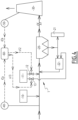
- a smoke treatment installation 1 is shown.
- This installation 1 is for example provided downstream of a household waste incinerator, not shown, whose combustion fumes are sent to the inlet of the installation 1.
- a similar installation can be found in coal or biomass thermal power stations.
- the fumes sent to plant 1 contain mercury, as well as, generally, other pollutants such as acid gases (HCl, SO 2 ), nitrogen oxides, dust and heavy metals other than mercury.
- the mercury contained in the fumes to be treated can be present in various forms, namely elemental, oxidized and particulate.
- the installation 1 comprises a gas-solid separator 20 which is based on a technology known per se.
- This gas-solid separator 20 is for example a bag filter or an electrostatic precipitator or a cyclonic unit or a device combining the latter.
- the gas-solid separator 20 typically operates at a temperature between 120°C and 250°C, that is to say that the temperature of the fumes entering the gas-solid separator 20 is in the aforementioned range.
- the installation 1 also comprises a silo 10 containing an acid gas neutralization reagent, such as lime or sodium bicarbonate.
- This acid gas neutralization reagent is introduced, from the silo 10, directly into the fumes to be treated upstream of the gas-solid separator 20, in order to neutralize the acid gases present in the fumes to be treated.
- the flow rate of the acid gas neutralization reagent is regulated according to the pollutant composition in the fumes to be treated.
- Installation 1 also includes a silo 11 containing a demercurization reagent.
- This demercurization reagent is introduced, from silo 11, directly into the fumes to be treated upstream of the gas-solid separator 20, in order to capture the mercury present in the fumes to be treated.
- the dispersion of the demercurization reagent is carried out in the duct where the fumes circulate or in a compartment dedicated to the adsorption of mercury.
- the form in which the demercurization reagent is introduced into the fumes is not limiting.
- the demercurization reagent can thus be solid, typically in powder form, but can also be liquid, typically in the form of droplets, as taught in WO 2019/081635 .
- the gas-solid separator 20 is suitable for separating the dust and solid reagents that the fumes contain when the latter pass through the gas-solid separator.
- the solids collected by the gas-solid separator 20 are divided into a first fraction, which is taken out of the installation 1, for example by being stored in a silo 21, and a second fraction which is recycled, by being returned to the fumes to be treated upstream of the gas-solid separator 20 by passing through a treatment device 22 where the solids of the recycled fraction are reactivated, in particular the used demercurization and neutralization reagents.
- This recycled fraction preferably represents between 50 and 95%, or even between 70 and 90%, of all the solids collected by the gas-solid separator 20.
- the treatment device 22 comprises a reactivation reactor, such as a fluidized bed, a mixing trough, a stirring drum, etc., this reactivation reactor acting chemically and/or mechanically and/or thermally on the solids present therein to reactivate them.
- the residence time of the recycled fraction in such a reactivation reactor is typically between 5 and 60 minutes.
- the treatment device 22 comprises a maturation enclosure, such as a silo, in which the reactivation results from an aging phenomenon.
- the residence time of the recycled fraction in such a maturation enclosure is typically between 5 and 20 hours.
- a fluid such as water droplets or water vapor
- WO2018/109072 thus discloses a reactivation reactor combining conveying propellers, mixing blades and water vapor distribution.
- the demercurization and neutralization reagents are partially or completely used up, in other words "deactivated", following their contact with the fumes to be treated upstream of the gas-solid separator 20.
- a layer of material on the surface of the particles of an alkaline reagent of the calcium hydroxide type is formed following the reaction with acid gases such as HCl, SO 2 , SO 3 and HF. This has the effect of reducing the capacity of the reagent with respect to the pollutants by a so-called shielding effect.
- the mercury in the fumes is generally trapped by adsorption.
- Reactivation by the treatment device 22 makes it possible to recover part of the capacities of the used reagents, in particular of the used demercurization reagent, and this by mechanical mixing which homogenizes the distribution of the pollutants in the solids, and/or by friction between particles to release the active sites, and/or by chemical reaction with liquid water or steam for example which allows for diffusion and redistribution of species between the surface and the core of the reagent.
- the solids leaving the treatment device 22 form a flow which is introduced directly into the fumes to be treated upstream of the gas-solid separator 20.
- the relative positions of the point of introduction of this flow into the fumes to be treated, of the point of introduction of the demercurization reagent from the silo 11 into the fumes to be treated, and of the point of introduction of the neutralization reagent from the silo 10 into the fumes to be treated are indifferent.
- the installation 1 is optionally completed by other treatment units, placed downstream of the gas-solid separator 20, such as a catalytic denitrification unit for example.
- other equipment such as a fan, a heat exchanger or a storage silo for another reagent may be present within the installation 1.
- the fumes treated by the installation 1 are intended to exit the latter via a chimney 30 through which the treated fumes are discharged into the environment.
- the concentration of mercury in the fumes to be treated i.e. the fumes entering installation 1
- the figure 2 illustrates the concentration, as a function of time, of total mercury vapour (elemental and oxidised) in fumes which come from a household waste incinerator and which are likely to be sent to installation 1 for the purposes of their treatment, in particular their demercurisation.
- the mercury concentration noted [Hg] is most often around a value of the order of 100 ⁇ g/Nm 3 , but that it experiences, on three occasions, mercury peaks during which the mercury concentration varies rapidly and with great intensity, reaching more than 800, or even 1000 ⁇ g/Nm 3 , in just a few seconds or tens of seconds.
- this installation 1 is designed to regulate mercury emissions at the outlet of installation 1, while taking into account the temporal evolution of the mercury concentration in the fumes to be treated entering the installation, including when this temporal evolution includes one or more mercury peaks.
- the mercury concentrations in the treated fumes could vary by more than two orders of magnitude in a few tens of seconds.
- installation 1 includes two analyzers 40 and 50, as well as a calculator 60.
- the analyzer 40 is adapted to, in real time, determine the concentration of mercury in the fumes both upstream of the point of introduction into the latter of the demercurization reagent from the silo 11 and upstream of the point of introduction into these fumes of the flow leaving the treatment device 22, as well as transmitting an information signal iCa representative of the value of this concentration, this upstream concentration value being called Ca hereinafter.
- the information signal iCa emitted by the analyzer 40 it is not necessary for the information signal iCa emitted by the analyzer 40 to be strictly continuous, in the sense that the upstream concentration values Ca determined by the analyzer 40 are to be provided, via the information signal iCa, at each instant, that is to say at each repetition of a predetermined time frequency, which is of the order of a minute and which is for example between thirty seconds and three minutes approximately.
- the analyzer 50 is adapted to, in real time, determine the concentration of mercury in the fumes downstream of the gas-solid separator 20, as well as transmit an information signal iCb representative of the value of this concentration, this downstream concentration value being called Cb hereinafter.
- This analyzer 50 is preferably placed in the chimney 30. Similar to the analyzer 40, it is not necessary for the information signal iCb emitted by the analyzer 50 to be a strictly continuous signal, in the sense that the downstream concentration values Cb determined by the analyzer 50 are to be provided, via the information signal iCb, at each instant, that is to say at each repetition of a predetermined time frequency, which is of the order of a minute and which is for example between thirty seconds and three minutes approximately.
- the analyzers 40 and 50 are based on technology known per se, which is not limiting of the invention.
- the analyzers 40 and 50 are each sensitive to one or more forms of mercury present in the fumes to be treated, such that their information signal iCa and iCb provides information on the concentration of total mercury or of a form of mercury contained in the fumes. It is thus not essential to have knowledge of the speciation of mercury in the fumes, because the information signals iCa and iCb are intended, as explained below, to be used to monitor the temporal evolution of the mercury concentration in the fumes to be treated, it being noted that the different forms of mercury generally experience the same temporal evolution of their concentration.
- the calculator 60 is, for its part, adapted to control in real time the dosage of the demercurization reagent introduced, from the silo 11, into the fumes upstream of the point of introduction of this demercurization reagent into the fumes to be treated.
- the calculator 60 is designed to continuously execute, that is to say repeatedly according to a predetermined time frequency, a sequence of calculations, which will be detailed later.
- the calculator 60 is connected to the analyzers 40 and 50 by any connection making it possible to transmit the information signals iCa and iCb from the analyzers 40 and 50 to the calculator 60.
- the calculator 60 is also connected to a member 12 which controls the flow of the demercurization reagent leaving the silo 11, this member 12 being for example a solenoid valve, a rotary airlock, a transport screw or any other means of transport and control of the flow rate of solid powder known to those skilled in the art.
- this member 12 being for example a solenoid valve, a rotary airlock, a transport screw or any other means of transport and control of the flow rate of solid powder known to those skilled in the art.
- the embodiment of the connection between the computer 60 and the member 12 is indifferent as long as it makes it possible to transmit, from the computer 60 to the member 12, a control signal s which is representative of the result of the sequence of calculations executed by the computer 60.
- the embodiment of the calculator 60 is not limiting since this calculator 60 is capable, in real time, of processing, in particular digitally, the information signals iCa and iCb by applying the aforementioned calculation sequence, as well as of emitting the control signal s.
- the calculator 60 can be an autonomous calculation unit, in particular in the form of a programmable automaton, or belong to a supervision system, in particular a computer system.
- the installation 1 is in steady state and that, after the acid gas neutralization reagent and the demercurization reagent have been introduced directly into the fumes to be treated upstream of the gas-solid separator 20 from the silo 10 and the silo 11 respectively, the fumes to be treated are sent to the gas-solid separator 20.
- the separation carried out by the latter leads to the formation of a filter cake in the gas-solid separator 20, attached for example to the filter sleeves of this separator, as well as to the recirculation, via the treatment device 22, of a portion of the solids collected by the gas-solid separator 20, namely the aforementioned recycled fraction.
- the demercurization reagent and the neutralization reagent are introduced into the fumes to be treated via the flow leaving the treatment device 22, due to the recirculation and reactivation of the recycled fraction.
- the demercurization reagent is dosed by implementing the following operations.
- the mercury concentration value Ce can therefore either mathematically associate the upstream concentration values Ca and downstream Cb, or be based only on one or the other of the upstream concentration values Ca and downstream Cb.
- the mercury concentration value Ce is preferably determined solely from the concentration of mercury in the fumes upstream of the points of introduction into the fumes to be treated of the demercurization reagent and of the flow leaving the treatment device 22, in particular solely from the upstream concentration value Ca, for example being equal to the latter: it is understood that the analyzer 50 is then not necessary within the installation 1 to have the mercury concentration value Cc, it being noted however that the presence of this analyzer 50 is often imposed for regulatory reasons independent of the invention.
- the mercury concentration value Ce is provided at all times to the calculator 60, in particular via the information signals iCa and/or iCb.
- mercury peaks can be monitored and/or reported in various ways, possibly by an operator, in other words not automatically, but manually.
- the occurrence of mercury peaks is preferentially detected from the mercury concentration value Cc, in particular from only the upstream concentration value Ca, by having the computer 60 execute a monitoring algorithm, known per se, applied to this concentration value Cc, where appropriate only Ca.
- a simple method is to subtract the mercury concentration measurement at time t from the previous measurement, for example t and t minus one minute in the case where the analyzers 40 and 50 each give a measurement every minute: if the value exceeds a pre-set threshold, this means that the increase in the concentration of mercury in the fumes has increased sharply over a very short period of time.
- This exceedance threshold is set according to the assessment of the person skilled in the art and the desired efficiency. In this case, the signal can be considered as a peak.
- a Savitzky-Golay filter is applied to the N values of the mercury concentration Cc, if applicable only of the upstream concentration Ca, determined just before the time considered, N being greater than or equal to 3, preferably 6.
- Other monitoring algorithms can be envisaged applied to the N values of the mercury concentration Cc, if applicable of the upstream concentration Ca, determined just before the time considered, N being greater than or equal to 3: as non-limiting examples, the monitoring algorithm used is based on the arithmetic moving average, the weighted moving average or the exponential moving average, calculated for the N aforementioned values.
- the dosage of the demercurization reagent is differentiated according to whether the moment considered belongs or not to a period which is associated with each mercury peak, this period beginning substantially at the peak of the mercury peak concerned, in other words in a summit region of the latter. It may in particular be provided that this period begins at a time when the mercury concentration value Ca or Cb or Ce exceeds a predetermined threshold, which is set according to the assessment of the person skilled in the art and the desired efficiency.
- operation b) provides, at each instant, to dose the demercurization reagent by applying to the mercury concentration value Cc a function f, which is pre-established and which increases with the mercury concentration value Ce.
- This function f is here pre-recorded in the calculator 60 and applied by the latter. The application of the function f makes it possible to order a specific dosage of the demercurization reagent and provides a value expressed for example in grams per normal m 3 of fumes.
- the function f increases with the mercury concentration value Cc, it is understood that the value, at which the demercurization reagent is dosed by the function f, is calculated low when the fumes to be treated contain little mercury and is calculated high when the fumes to be treated contain a lot of mercury.
- operation b) provides, at each instant, to dose the demercurization reagent by applying to the mercury concentration value Cc a function g, which is different from function f and which is pre-established, being here pre-recorded in the calculator 60 and applied by the latter.
- function g makes it possible to control a specific dosage of the demercurization reagent, by providing a value expressed for example in grams per normal m 3 of fumes, but function g is provided so that the value at which the demercurization reagent is dosed by function g is greater than that at which the demercurization reagent is dosed by function f at the instant considered.
- the function g is decreasing with time until the demercurization reagent is dosed at a value equal to or less than that at which the demercurization reagent is dosed by the function f at a time when the aforementioned period ends.
- the aforementioned period typically lasts at least 10 minutes, or even 15 minutes.
- the application of the function g commands a slower decrease for the dosage of the demercurization reagent following a mercury peak, which amounts to saying that this dosage is “extended”.
- the value at which the demercurization reagent is dosed is, at each instant, used to control the member 12, being here transmitted via the control signal s generated by the computer 60.
- the value at which the demercurization reagent is dosed at the end of operation b) is adjusted by feedback, at each instant, from the mercury concentration in the fumes downstream of the gas-solid separator 20, in particular from the downstream concentration value Cb.
- the optional operation c) makes it possible to apply an adjustment feedback on the dosage value resulting from operation b).
- the correction applied by operation c) is known per se and can in particular be implemented by a PID algorithm (acronym for “proportional, integral, derivative”), here executed by the computer 60.
- the solid curve on the figure 3 which is associated with the left scale, is the time evolution of the upstream concentration value Ca, in other words the time evolution of the mercury concentration in the fumes to be treated, determined by the analyzer 40.
- the upstream concentration value Ca can be associated with the measurement of the total mercury concentration, or the elemental mercury concentration or possibly the oxidized mercury fraction. In practice, the choice of what is actually measured through the upstream concentration value Ca is left to the discretion of the person skilled in the art, taking into account the specificities of the analyzer 40, the constraints of the process, or by economic choice. As mentioned above, it is sufficient that the upstream concentration value Ca is representative of the quantity of mercury to be treated by the installation.
- the most intense mercury peak is associated with a value of approximately 2200 ⁇ g/Nm 3 for the upstream concentration value Ca.
- the curve of the figure 3 is obviously not flat, but does not show other mercury peaks, as manually appreciated by the operator or as automatically detected by the computer 60, as explained above.
- the dotted curve and the dashed curve which are both associated with the same scale on the right of the graph of the figure 3 , show the temporal evolution of, respectively, the dosage value by the function f and the dosage value resulting from operation b).
- the comparison between the dotted curve and the dashed curve shows that, during each of the mercury peaks, the dosage value resulting from operation b) is slowed down over time compared to the dosage value by the function f.
- the dosage value resulting from operation b) is controlled by applying function g, by slowing down its temporal decrease compared to the application of function f, which amounts to saying that the quantity of demercurization reagent is significantly increased.
- the dosage value resulting from operation b) is controlled by applying function f.
- mercury in particular elemental mercury
- mercury present in large quantities during mercury peaks is less well fixed in the long term, in particular when the demercurization reagent used is not chemically impregnated.
- mercury is trapped mainly by physisorption, following a transfer from the gas phase to the solid phase in a reversible manner, that is to say that the direction of the transfer is reversed in the event of a temperature increase or a net decrease in the mercury concentration in the fumes for example.
- the dosage of the demercurization reagent allows, during mercury peaks, that the mercury captured in the saturated reagents is transferred to fresh reagent during recycling and reactivation via the treatment device 22.
- An addition of fluid, such as water vapor or fine droplets of liquid water, preferably with mechanical stirring, within the treatment device 22, makes it possible to accelerate the process and force the mercury to attach to the most energetic sites of the demercurization reagents.
- the method thus makes it possible to effectively deal with a mercury peak occurring in the treatment of the fumes.
- the recirculation and reactivation of the recycled fraction effectively reduce the mercury concentration in the fumes following a sudden arrival of mercury.
- the "extended" injection of the demercurization reagent and the reactivation of the reagents make it possible to fix the mercury durably and to avoid its re-emission in the fumes.
- the positive effects of the process according to the invention are thus multiple: reducing mercury emissions into the atmosphere, protecting the equipment of the installation which could be poisoned by mercury, avoiding uncontrolled mercury emissions, for example the adsorption and release cycles of mercury in the catalytic denitrification reactors located downstream of the gas-solid separator 20.
- the demercurization reagent from the silo 11 may not be introduced in its entirety directly into the fumes to be treated, but at least in part directly into the treatment device 22.
- the installation 1 comprises a member 13 which controls the flow of demercurization reagent from the silo 11 and introduced directly into the treatment device 22.
- the portion of the demercurization reagent introduced directly into the treatment device 22 then joins the fumes to be treated, via the flow leaving the treatment device 22.
- This arrangement of the process, illustrated in the figure 4 allows fresh demercurization reagent to be brought into contact directly with the recycled fraction of the solids collected by the gas-solid separator 20, allowing the mercury to be fixed more permanently if necessary.
- the demercurization reagent is distributed between the silo 11 and the silo 14. More specifically, the demercurization reagent comprises both a first demercurization reagent, which is contained in the silo 11, and a second demercurization reagent, which is contained in the silo 14 and which is different from the first demercurization reagent in that it has a demercurizing activity greater than that of the first demercurization reagent.
- the second demercurization reagent has demercurization properties that are complementary to or more advanced than those of the first demercurization reagent.
- the first demercurization reagent is not chemically impregnated, while the second demercurization reagent is chemically impregnated.
- the method described above is unchanged, except that, outside the aforementioned period associated with each mercury peak, the first demercurization reagent is used but not the second demercurization reagent, while during the aforementioned period associated with each mercury peak, the second demercurization reagent is used and, optionally, the first demercurization reagent is also used.
- the silo 14 is associated with a member 15 which controls the flow of the second demercurization reagent: during the implementation of the method, the dosage value resulting at each instant from operation b) or, where appropriate, from the optional operation c), is applied to one and/or the other of the silos 11 and 14, being here transmitted via respective control signals, denoted s12 and s15 on the figure 5 .
- This arrangement of the process, illustrated in the figure 5 allows mercury to be fixed efficiently in an optimal and economical manner.
Landscapes
- Chemical & Material Sciences (AREA)
- Engineering & Computer Science (AREA)
- General Chemical & Material Sciences (AREA)
- Environmental & Geological Engineering (AREA)
- Biomedical Technology (AREA)
- Analytical Chemistry (AREA)
- Health & Medical Sciences (AREA)
- Oil, Petroleum & Natural Gas (AREA)
- Chemical Kinetics & Catalysis (AREA)
- Life Sciences & Earth Sciences (AREA)
- Sustainable Development (AREA)
- Treating Waste Gases (AREA)
- Compounds Of Alkaline-Earth Elements, Aluminum Or Rare-Earth Metals (AREA)
Claims (12)
- Verfahren zur Entfernung von Quecksilber aus Rauchgasen,wobei die zu behandelnden Rauchgase zu einem Feststoffgasabscheider (20) geleitet werden,wobei ein Reagenz zur Entfernung von Quecksilber stromaufwärts von dem Feststoffgasabscheider in die Rauchgase eingeleitet wird,wobei eine recycelte Fraktion der Feststoffe, die von dem Feststoffgasabscheider gesammelt werden, zu einer Behandlungsvorrichtung (22) geleitet wird, um dort reaktiviert zu werden, bevor sie über einen aus der Behandlungsvorrichtung austretenden Strom stromaufwärts von dem Feststoffgasabscheider in die Rauchgase eingeleitet wird,und wobei das Quecksilberentfernungsreagenz dosiert wird, indem zu jedem Zeitpunkt die folgenden Vorgänge durchgeführt werden:a) ein Quecksilberkonzentrationswert (Cc) wird bestimmt aus (i) der Quecksilberkonzentration in dem Rauchgas stromaufwärts von den Einleitungsstellen des Quecksilberentfernungsreagenz und des aus der Behandlungsvorrichtung (22) austretenden Stroms in das Rauchgas, und/oder (ii) der Quecksilberkonzentration in dem Rauchgas stromabwärts von dem Feststoffgasabscheider (20), undb) das Auftreten von Quecksilberspitzen wird berücksichtigt, sodass:- außerhalb eines Zeitraums (P1, P2), der im Wesentlichen mit dem Höhepunkt von jeder Quecksilberspitze beginnt, wird das Quecksilberentfernungsreagenz dosiert, indem auf den Quecksilberkonzentrationswert (Cc) eine erste Dosierungsfunktion (f) angewendet wird, die mit dem Quecksilberkonzentrationswert (Cc) ansteigt, und- während der genannten Periode (P1, P2) wird das Quecksilberentfernungsreagenz dosiert, indem auf den Wert der Quecksilberkonzentration (Cc) eine zweite Dosierungsfunktion (g) angewendet wird, die das Quecksilberentfernungsreagenz auf einen Wert dosiert, der größer ist als der Wert, bei dem das Quecksilberentfernungsreagenz durch die erste Dosierungsfunktion (f) zu dem betrachteten Zeitpunkt dosiert wird, wobei die zweite Dosierfunktion mit der Zeit abnimmt, bis sie das Quecksilberentfernungsreagenz auf einen Wert dosiert, der gleich wie oder kleiner als der Wert ist, auf den das Quecksilberentfernungsreagenz durch die erste Dosierfunktion zu einem Zeitpunkt dosiert wird, an dem der Zeitraum endet.
- Verfahren nach Anspruch 1, wobei das Auftreten von Quecksilberspitzen erfasst wird, indem zu jedem Zeitpunkt ein Überwachungsalgorithmus auf den Wert der Quecksilberkonzentration (Cc) angewendet wird.
- Verfahren nach Anspruch 2, wobei der Überwachungsalgorithmus zu jedem Zeitpunkt auf die N Werte der Quecksilberkonzentration (Cc) angewendet wird, die unmittelbar vor dem jeweiligen Zeitpunkt bestimmt wurden, wobei N gleich wie oder größer als drei ist.
- Verfahren nach Anspruch 1, wobei das Auftreten von Quecksilberspitzen überwacht und von einem Bediener manuell notiert wird.
- Verfahren nach einem der vorherigen Ansprüche, wobei zu jedem Zeitpunkt durch Rückkopplung der Wert, auf den das Quecksilberentfernungsreagenz am Ende von Vorgang b) dosiert wird, anhand der Quecksilberkonzentration in den Rauchgasen stromabwärts von dem Feststoffgasabscheider (20) angepasst wird, insbesondere unter Verwendung eines PID-Algorithmus.
- Verfahren nach einem der vorherigen Ansprüche, wobei die Verarbeitungsvorrichtung (22) einen Reaktivierungsreaktor umfasst, in dem die Verweilzeit der recycelten Fraktion zwischen 5 und 60 Minuten liegt.
- Verfahren nach einem der vorherigen Ansprüche, wobei die Verarbeitungsvorrichtung (22) einen Reifungsraum umfasst, in dem die Verweilzeit der recycelten Fraktion zwischen 5 und 20 Stunden liegt.
- Verfahren nach einem der vorherigen Ansprüche, wobei dem ein Fluid, wie beispielsweise Wassertröpfchen oder Wasserdampf, in die Behandlungsvorrichtung (22) eingelassen wird, um mit der recycelten Fraktion in Kontakt gebracht zu werden.
- Verfahren nach einem der vorherigen Ansprüche, wobei die recycelte Fraktion zwischen 50 und 95 %, vorzugsweise zwischen 70 und 90 %, der gesamten Feststoffe darstellt, die von dem Feststoffgasabscheider (20) gesammelt werden.
- Verfahren nach einem der vorherigen Ansprüche, wobei das gesamte oder ein Teil des Quecksilberentfernungsreagenz stromaufwärts von dem Feststoffgasabscheider (20) direkt in die Rauchgase eingeleitet wird.
- Verfahren nach einem der vorherigen Ansprüche, wobei das gesamte oder ein Teil des Quecksilberentfernungsreagenz stromaufwärts von dem Feststoffgasabscheider (20) direkt in die Behandlungsvorrichtung (22) eingeleitet wird.
- Verfahren nach einem der vorherigen Ansprüche, wobei das Quecksilberentfernungsreagenz ferner Folgendes beinhaltet:- ein erstes Quecksilberentfernungsreagenz, das außerhalb des Zeitraums (P1, P2) und optional während des Zeitraums verwendet wird, und- ein zweites Quecksilberentfernungsreagenz, das eine höhere Quecksilberentfernungsaktivität als das erste Quecksilberentfernungsreagenz aufweist und das während des Zeitraums, aber nicht außerhalb des Zeitraums verwendet wird.
Applications Claiming Priority (1)
| Application Number | Priority Date | Filing Date | Title |
|---|---|---|---|
| FR2205138A FR3135906B1 (fr) | 2022-05-30 | 2022-05-30 | Procédé de démercurisation de fumées |
Publications (2)
| Publication Number | Publication Date |
|---|---|
| EP4286033A1 EP4286033A1 (de) | 2023-12-06 |
| EP4286033B1 true EP4286033B1 (de) | 2024-11-20 |
Family
ID=82319802
Family Applications (1)
| Application Number | Title | Priority Date | Filing Date |
|---|---|---|---|
| EP23159069.6A Active EP4286033B1 (de) | 2022-05-30 | 2023-02-28 | Verfahren zur entfernung von quecksilber aus rauchgasen |
Country Status (5)
| Country | Link |
|---|---|
| EP (1) | EP4286033B1 (de) |
| DK (1) | DK4286033T3 (de) |
| FI (1) | FI4286033T3 (de) |
| FR (1) | FR3135906B1 (de) |
| WO (1) | WO2023232698A1 (de) |
Family Cites Families (6)
| Publication number | Priority date | Publication date | Assignee | Title |
|---|---|---|---|---|
| FR3060417B1 (fr) | 2016-12-15 | 2019-05-24 | Lab Sa | Reacteur de reactivation de solides |
| FR3072887B1 (fr) | 2017-10-26 | 2022-05-13 | Lab Sa | Procede de demercurisation d'effluents gazeux |
| JP7106357B2 (ja) * | 2018-06-06 | 2022-07-26 | 日立造船株式会社 | 排ガス処理装置 |
| FR3083128B1 (fr) * | 2018-06-27 | 2020-12-04 | Lab Sa | Procede de demercurisation d'effluents gazeux |
| JP6439207B1 (ja) * | 2018-06-29 | 2018-12-19 | 三菱重工環境・化学エンジニアリング株式会社 | 排ガス水銀除去システム |
| JP7269865B2 (ja) * | 2019-10-21 | 2023-05-09 | 日立造船株式会社 | 排ガス処理装置および排ガス処理方法 |
-
2022
- 2022-05-30 FR FR2205138A patent/FR3135906B1/fr active Active
-
2023
- 2023-02-28 DK DK23159069.6T patent/DK4286033T3/da active
- 2023-02-28 EP EP23159069.6A patent/EP4286033B1/de active Active
- 2023-02-28 FI FIEP23159069.6T patent/FI4286033T3/fi active
- 2023-05-26 WO PCT/EP2023/064229 patent/WO2023232698A1/fr not_active Ceased
Also Published As
| Publication number | Publication date |
|---|---|
| FI4286033T3 (fi) | 2024-12-20 |
| WO2023232698A1 (fr) | 2023-12-07 |
| FR3135906A1 (fr) | 2023-12-01 |
| FR3135906B1 (fr) | 2024-05-31 |
| DK4286033T3 (da) | 2024-12-09 |
| EP4286033A1 (de) | 2023-12-06 |
Similar Documents
| Publication | Publication Date | Title |
|---|---|---|
| EP1949956B1 (de) | Verfahren und Anlage zur Klärung von Dämpfen, die saure Schadstoffe enthalten | |
| WO2018115499A1 (fr) | Procede et installation de denitrification des fumees de combustion | |
| EP3002060A1 (de) | Regenerierungsverfahren und anlage eines strukturierten denitrifikationskatalysators | |
| EP3386610A1 (de) | Verfahren zur behandlung von rauchgasen aus einem verbrennungs- oder kalzinierungsofen und anlage zur durchführung solch eines verfahrens | |
| EP4286033B1 (de) | Verfahren zur entfernung von quecksilber aus rauchgasen | |
| EP2397214B1 (de) | Verfahren zur Rauchgasaufbereitung | |
| WO1992019364A1 (fr) | Procede d'epuration de fumees contenant des polluants organiques condensables | |
| EP4008425B1 (de) | Verfahren zur entfernung von quecksilber aus rauchgasen | |
| FR3008322A1 (fr) | Procede d'epuration de fumees de combustion | |
| FR2681795A1 (fr) | Procede pour epurer un gaz contenant de l'oxyde nitrique et du dioxyde de soufre. | |
| EP2465598B1 (de) | Verfahren zur Rauchgasreinigung | |
| EP2397213B1 (de) | Verfahren zur Steuerung des Korrosionsrisikos bei Abgasaufbereitungsverfahren | |
| FR2717297A1 (fr) | Procédé et installation d'épuration de fumées issues de l'incinération de déchets faiblement radioactifs. | |
| EP2851116B1 (de) | Verfahren zur katalytischen Reinigung von Rauchgasen, die Stickoxide enthalten | |
| WO2002045824A1 (fr) | Procede et installation d'epuration de fumees de cimenterie | |
| CN120426573B (zh) | 一种垃圾焚烧烟气处理方法及烟气处理装置 | |
| JPH10296046A (ja) | 排ガス中酸性成分の除去方法 | |
| JPH10216463A (ja) | 消石灰と吸着剤の噴霧方法及び装置 | |
| FR2992638B1 (fr) | Procede et installation de traitement de boues sechees de station d'epuration pour eviter ou limiter leur auto-echauffement | |
| EP3586944A1 (de) | Verfahren zur beseitigung von quecksilber aus abgasen | |
| EP2719444B1 (de) | Katalytisches Denitrifikationsverfahren für Verbrennungsabgase | |
| FR2717249A1 (fr) | Procédé et installation d'épuration de fumées issues d'un incinérateur à fusion et vitrification des déchets. | |
| KR100306292B1 (ko) | 소각연도가스처리방법 | |
| FR3046087A1 (fr) | Installation de traitement de fumees et procede de traitement des fumees au sein d'une telle installation | |
| JP2022079966A (ja) | 処理システム及び処理方法 |
Legal Events
| Date | Code | Title | Description |
|---|---|---|---|
| PUAI | Public reference made under article 153(3) epc to a published international application that has entered the european phase |
Free format text: ORIGINAL CODE: 0009012 |
|
| STAA | Information on the status of an ep patent application or granted ep patent |
Free format text: STATUS: THE APPLICATION HAS BEEN PUBLISHED |
|
| STAA | Information on the status of an ep patent application or granted ep patent |
Free format text: STATUS: REQUEST FOR EXAMINATION WAS MADE |
|
| AK | Designated contracting states |
Kind code of ref document: A1 Designated state(s): AL AT BE BG CH CY CZ DE DK EE ES FI FR GB GR HR HU IE IS IT LI LT LU LV MC ME MK MT NL NO PL PT RO RS SE SI SK SM TR |
|
| 17P | Request for examination filed |
Effective date: 20231121 |
|
| RBV | Designated contracting states (corrected) |
Designated state(s): AL AT BE BG CH CY CZ DE DK EE ES FI FR GB GR HR HU IE IS IT LI LT LU LV MC ME MK MT NL NO PL PT RO RS SE SI SK SM TR |
|
| P01 | Opt-out of the competence of the unified patent court (upc) registered |
Effective date: 20231213 |
|
| STAA | Information on the status of an ep patent application or granted ep patent |
Free format text: STATUS: EXAMINATION IS IN PROGRESS |
|
| 17Q | First examination report despatched |
Effective date: 20240226 |
|
| GRAP | Despatch of communication of intention to grant a patent |
Free format text: ORIGINAL CODE: EPIDOSNIGR1 |
|
| STAA | Information on the status of an ep patent application or granted ep patent |
Free format text: STATUS: GRANT OF PATENT IS INTENDED |
|
| INTG | Intention to grant announced |
Effective date: 20240626 |
|
| GRAS | Grant fee paid |
Free format text: ORIGINAL CODE: EPIDOSNIGR3 |
|
| GRAA | (expected) grant |
Free format text: ORIGINAL CODE: 0009210 |
|
| STAA | Information on the status of an ep patent application or granted ep patent |
Free format text: STATUS: THE PATENT HAS BEEN GRANTED |
|
| AK | Designated contracting states |
Kind code of ref document: B1 Designated state(s): AL AT BE BG CH CY CZ DE DK EE ES FI FR GB GR HR HU IE IS IT LI LT LU LV MC ME MK MT NL NO PL PT RO RS SE SI SK SM TR |
|
| REG | Reference to a national code |
Ref country code: GB Ref legal event code: FG4D Free format text: NOT ENGLISH |
|
| REG | Reference to a national code |
Ref country code: CH Ref legal event code: EP |
|
| REG | Reference to a national code |
Ref country code: DK Ref legal event code: T3 Effective date: 20241203 |
|
| REG | Reference to a national code |
Ref country code: NL Ref legal event code: FP |
|
| REG | Reference to a national code |
Ref country code: DE Ref legal event code: R096 Ref document number: 602023001050 Country of ref document: DE |
|
| REG | Reference to a national code |
Ref country code: IE Ref legal event code: FG4D Free format text: LANGUAGE OF EP DOCUMENT: FRENCH |
|
| REG | Reference to a national code |
Ref country code: FI Ref legal event code: FGE |
|
| REG | Reference to a national code |
Ref country code: SE Ref legal event code: TRGR |
|
| REG | Reference to a national code |
Ref country code: LT Ref legal event code: MG9D |
|
| PG25 | Lapsed in a contracting state [announced via postgrant information from national office to epo] |
Ref country code: IS Free format text: LAPSE BECAUSE OF FAILURE TO SUBMIT A TRANSLATION OF THE DESCRIPTION OR TO PAY THE FEE WITHIN THE PRESCRIBED TIME-LIMIT Effective date: 20250320 Ref country code: PT Free format text: LAPSE BECAUSE OF FAILURE TO SUBMIT A TRANSLATION OF THE DESCRIPTION OR TO PAY THE FEE WITHIN THE PRESCRIBED TIME-LIMIT Effective date: 20250320 Ref country code: HR Free format text: LAPSE BECAUSE OF FAILURE TO SUBMIT A TRANSLATION OF THE DESCRIPTION OR TO PAY THE FEE WITHIN THE PRESCRIBED TIME-LIMIT Effective date: 20241120 |
|
| REG | Reference to a national code |
Ref country code: AT Ref legal event code: MK05 Ref document number: 1743086 Country of ref document: AT Kind code of ref document: T Effective date: 20241120 |
|
| PG25 | Lapsed in a contracting state [announced via postgrant information from national office to epo] |
Ref country code: BG Free format text: LAPSE BECAUSE OF FAILURE TO SUBMIT A TRANSLATION OF THE DESCRIPTION OR TO PAY THE FEE WITHIN THE PRESCRIBED TIME-LIMIT Effective date: 20241120 |
|
| PG25 | Lapsed in a contracting state [announced via postgrant information from national office to epo] |
Ref country code: ES Free format text: LAPSE BECAUSE OF FAILURE TO SUBMIT A TRANSLATION OF THE DESCRIPTION OR TO PAY THE FEE WITHIN THE PRESCRIBED TIME-LIMIT Effective date: 20241120 |
|
| PG25 | Lapsed in a contracting state [announced via postgrant information from national office to epo] |
Ref country code: NO Free format text: LAPSE BECAUSE OF FAILURE TO SUBMIT A TRANSLATION OF THE DESCRIPTION OR TO PAY THE FEE WITHIN THE PRESCRIBED TIME-LIMIT Effective date: 20250220 |
|
| PG25 | Lapsed in a contracting state [announced via postgrant information from national office to epo] |
Ref country code: GR Free format text: LAPSE BECAUSE OF FAILURE TO SUBMIT A TRANSLATION OF THE DESCRIPTION OR TO PAY THE FEE WITHIN THE PRESCRIBED TIME-LIMIT Effective date: 20250221 Ref country code: LV Free format text: LAPSE BECAUSE OF FAILURE TO SUBMIT A TRANSLATION OF THE DESCRIPTION OR TO PAY THE FEE WITHIN THE PRESCRIBED TIME-LIMIT Effective date: 20241120 Ref country code: AT Free format text: LAPSE BECAUSE OF FAILURE TO SUBMIT A TRANSLATION OF THE DESCRIPTION OR TO PAY THE FEE WITHIN THE PRESCRIBED TIME-LIMIT Effective date: 20241120 |
|
| PG25 | Lapsed in a contracting state [announced via postgrant information from national office to epo] |
Ref country code: PL Free format text: LAPSE BECAUSE OF FAILURE TO SUBMIT A TRANSLATION OF THE DESCRIPTION OR TO PAY THE FEE WITHIN THE PRESCRIBED TIME-LIMIT Effective date: 20241120 |
|
| PG25 | Lapsed in a contracting state [announced via postgrant information from national office to epo] |
Ref country code: RS Free format text: LAPSE BECAUSE OF FAILURE TO SUBMIT A TRANSLATION OF THE DESCRIPTION OR TO PAY THE FEE WITHIN THE PRESCRIBED TIME-LIMIT Effective date: 20250220 |
|
| PG25 | Lapsed in a contracting state [announced via postgrant information from national office to epo] |
Ref country code: SM Free format text: LAPSE BECAUSE OF FAILURE TO SUBMIT A TRANSLATION OF THE DESCRIPTION OR TO PAY THE FEE WITHIN THE PRESCRIBED TIME-LIMIT Effective date: 20241120 |
|
| PG25 | Lapsed in a contracting state [announced via postgrant information from national office to epo] |
Ref country code: EE Free format text: LAPSE BECAUSE OF FAILURE TO SUBMIT A TRANSLATION OF THE DESCRIPTION OR TO PAY THE FEE WITHIN THE PRESCRIBED TIME-LIMIT Effective date: 20241120 |
|
| PG25 | Lapsed in a contracting state [announced via postgrant information from national office to epo] |
Ref country code: RO Free format text: LAPSE BECAUSE OF FAILURE TO SUBMIT A TRANSLATION OF THE DESCRIPTION OR TO PAY THE FEE WITHIN THE PRESCRIBED TIME-LIMIT Effective date: 20241120 |
|
| PG25 | Lapsed in a contracting state [announced via postgrant information from national office to epo] |
Ref country code: SK Free format text: LAPSE BECAUSE OF FAILURE TO SUBMIT A TRANSLATION OF THE DESCRIPTION OR TO PAY THE FEE WITHIN THE PRESCRIBED TIME-LIMIT Effective date: 20241120 |
|
| REG | Reference to a national code |
Ref country code: DE Ref legal event code: R097 Ref document number: 602023001050 Country of ref document: DE |
|
| PG25 | Lapsed in a contracting state [announced via postgrant information from national office to epo] |
Ref country code: MC Free format text: LAPSE BECAUSE OF FAILURE TO SUBMIT A TRANSLATION OF THE DESCRIPTION OR TO PAY THE FEE WITHIN THE PRESCRIBED TIME-LIMIT Effective date: 20241120 |
|
| PLBE | No opposition filed within time limit |
Free format text: ORIGINAL CODE: 0009261 |
|
| STAA | Information on the status of an ep patent application or granted ep patent |
Free format text: STATUS: NO OPPOSITION FILED WITHIN TIME LIMIT |
|
| PG25 | Lapsed in a contracting state [announced via postgrant information from national office to epo] |
Ref country code: LU Free format text: LAPSE BECAUSE OF NON-PAYMENT OF DUE FEES Effective date: 20250228 |
|
| 26N | No opposition filed |
Effective date: 20250821 |
|
| REG | Reference to a national code |
Ref country code: BE Ref legal event code: MM Effective date: 20250228 |
|
| REG | Reference to a national code |
Ref country code: CH Ref legal event code: R18 Free format text: ST27 STATUS EVENT CODE: U-0-0-R10-R18 (AS PROVIDED BY THE NATIONAL OFFICE) Effective date: 20260106 |
|
| PG25 | Lapsed in a contracting state [announced via postgrant information from national office to epo] |
Ref country code: BE Free format text: LAPSE BECAUSE OF NON-PAYMENT OF DUE FEES Effective date: 20250228 |
|
| PG25 | Lapsed in a contracting state [announced via postgrant information from national office to epo] |
Ref country code: IE Free format text: LAPSE BECAUSE OF NON-PAYMENT OF DUE FEES Effective date: 20250228 |
|
| PGFP | Annual fee paid to national office [announced via postgrant information from national office to epo] |
Ref country code: NL Payment date: 20260127 Year of fee payment: 4 |
|
| REG | Reference to a national code |
Ref country code: CH Ref legal event code: U11 Free format text: ST27 STATUS EVENT CODE: U-0-0-U10-U11 (AS PROVIDED BY THE NATIONAL OFFICE) Effective date: 20260301 |
|
| PGFP | Annual fee paid to national office [announced via postgrant information from national office to epo] |
Ref country code: SE Payment date: 20260219 Year of fee payment: 4 |
|
| PGFP | Annual fee paid to national office [announced via postgrant information from national office to epo] |
Ref country code: DK Payment date: 20260129 Year of fee payment: 4 Ref country code: DE Payment date: 20260206 Year of fee payment: 4 |
|
| PGFP | Annual fee paid to national office [announced via postgrant information from national office to epo] |
Ref country code: FI Payment date: 20260120 Year of fee payment: 4 Ref country code: IT Payment date: 20260228 Year of fee payment: 4 |
|
| PGFP | Annual fee paid to national office [announced via postgrant information from national office to epo] |
Ref country code: FR Payment date: 20260112 Year of fee payment: 4 |
|
| PGFP | Annual fee paid to national office [announced via postgrant information from national office to epo] |
Ref country code: CH Payment date: 20260301 Year of fee payment: 4 Ref country code: CZ Payment date: 20260130 Year of fee payment: 4 |