EP4008425B1 - Verfahren zur entfernung von quecksilber aus rauchgasen - Google Patents
Verfahren zur entfernung von quecksilber aus rauchgasen Download PDFInfo
- Publication number
- EP4008425B1 EP4008425B1 EP21212233.7A EP21212233A EP4008425B1 EP 4008425 B1 EP4008425 B1 EP 4008425B1 EP 21212233 A EP21212233 A EP 21212233A EP 4008425 B1 EP4008425 B1 EP 4008425B1
- Authority
- EP
- European Patent Office
- Prior art keywords
- mercury
- instant
- fumes
- value
- upstream
- Prior art date
- Legal status (The legal status is an assumption and is not a legal conclusion. Google has not performed a legal analysis and makes no representation as to the accuracy of the status listed.)
- Active
Links
Images


Classifications
-
- B—PERFORMING OPERATIONS; TRANSPORTING
- B01—PHYSICAL OR CHEMICAL PROCESSES OR APPARATUS IN GENERAL
- B01D—SEPARATION
- B01D53/00—Separation of gases or vapours; Recovering vapours of volatile solvents from gases; Chemical or biological purification of waste gases, e.g. engine exhaust gases, smoke, fumes, flue gases, aerosols
- B01D53/34—Chemical or biological purification of waste gases
- B01D53/46—Removing components of defined structure
- B01D53/64—Heavy metals or compounds thereof, e.g. mercury
-
- B—PERFORMING OPERATIONS; TRANSPORTING
- B01—PHYSICAL OR CHEMICAL PROCESSES OR APPARATUS IN GENERAL
- B01D—SEPARATION
- B01D53/00—Separation of gases or vapours; Recovering vapours of volatile solvents from gases; Chemical or biological purification of waste gases, e.g. engine exhaust gases, smoke, fumes, flue gases, aerosols
- B01D53/30—Controlling by gas-analysis apparatus
-
- B—PERFORMING OPERATIONS; TRANSPORTING
- B01—PHYSICAL OR CHEMICAL PROCESSES OR APPARATUS IN GENERAL
- B01D—SEPARATION
- B01D53/00—Separation of gases or vapours; Recovering vapours of volatile solvents from gases; Chemical or biological purification of waste gases, e.g. engine exhaust gases, smoke, fumes, flue gases, aerosols
- B01D53/34—Chemical or biological purification of waste gases
- B01D53/346—Controlling the process
-
- B—PERFORMING OPERATIONS; TRANSPORTING
- B01—PHYSICAL OR CHEMICAL PROCESSES OR APPARATUS IN GENERAL
- B01D—SEPARATION
- B01D53/00—Separation of gases or vapours; Recovering vapours of volatile solvents from gases; Chemical or biological purification of waste gases, e.g. engine exhaust gases, smoke, fumes, flue gases, aerosols
- B01D53/34—Chemical or biological purification of waste gases
- B01D53/74—General processes for purification of waste gases; Apparatus or devices specially adapted therefor
- B01D53/81—Solid phase processes
- B01D53/83—Solid phase processes with moving reactants
-
- F—MECHANICAL ENGINEERING; LIGHTING; HEATING; WEAPONS; BLASTING
- F23—COMBUSTION APPARATUS; COMBUSTION PROCESSES
- F23J—REMOVAL OR TREATMENT OF COMBUSTION PRODUCTS OR COMBUSTION RESIDUES; FLUES
- F23J15/00—Arrangements of devices for treating smoke or fumes
- F23J15/02—Arrangements of devices for treating smoke or fumes of purifiers, e.g. for removing noxious material
-
- B—PERFORMING OPERATIONS; TRANSPORTING
- B01—PHYSICAL OR CHEMICAL PROCESSES OR APPARATUS IN GENERAL
- B01D—SEPARATION
- B01D2251/00—Reactants
- B01D2251/10—Oxidants
- B01D2251/108—Halogens or halogen compounds
-
- B—PERFORMING OPERATIONS; TRANSPORTING
- B01—PHYSICAL OR CHEMICAL PROCESSES OR APPARATUS IN GENERAL
- B01D—SEPARATION
- B01D2253/00—Adsorbents used in seperation treatment of gases and vapours
- B01D2253/10—Inorganic adsorbents
- B01D2253/102—Carbon
-
- B—PERFORMING OPERATIONS; TRANSPORTING
- B01—PHYSICAL OR CHEMICAL PROCESSES OR APPARATUS IN GENERAL
- B01D—SEPARATION
- B01D2257/00—Components to be removed
- B01D2257/60—Heavy metals or heavy metal compounds
- B01D2257/602—Mercury or mercury compounds
-
- B—PERFORMING OPERATIONS; TRANSPORTING
- B01—PHYSICAL OR CHEMICAL PROCESSES OR APPARATUS IN GENERAL
- B01D—SEPARATION
- B01D2258/00—Sources of waste gases
- B01D2258/02—Other waste gases
- B01D2258/0283—Flue gases
-
- F—MECHANICAL ENGINEERING; LIGHTING; HEATING; WEAPONS; BLASTING
- F23—COMBUSTION APPARATUS; COMBUSTION PROCESSES
- F23J—REMOVAL OR TREATMENT OF COMBUSTION PRODUCTS OR COMBUSTION RESIDUES; FLUES
- F23J2215/00—Preventing emissions
- F23J2215/60—Heavy metals; Compounds thereof
-
- F—MECHANICAL ENGINEERING; LIGHTING; HEATING; WEAPONS; BLASTING
- F23—COMBUSTION APPARATUS; COMBUSTION PROCESSES
- F23J—REMOVAL OR TREATMENT OF COMBUSTION PRODUCTS OR COMBUSTION RESIDUES; FLUES
- F23J2219/00—Treatment devices
- F23J2219/30—Sorption devices using carbon, e.g. coke
Definitions
- the present invention relates to a process for demercurizing smoke.
- Mercury is a naturally occurring compound that is still used significantly in industry. Mercury is toxic in all its forms. It can be assimilated by practically all living organisms and is therefore concentrated during the food chain. Ultimately, it is absorbed by humans and develops its toxicity there. From this point of view, it is of little importance whether mercury is present in the form of a metal, organic salts or organic compounds such as methylmercury.
- Another approach consists of implementing processes for treating the flow, liquid or gas, transporting mercury.
- the invention thus concerns processes for demercurizing smoke from combustion installations containing mercury vapors.
- wet processes the fumes are washed and the mercury and other pollutants contained in the fumes are transferred to the liquid phase where they are then precipitated, stabilized and separated.
- the mercury is captured by a demercurization reagent, such as adsorbents, typically activated carbon, lignite coke, halogenated additives, and sulfur additives, to name but a few.
- This demercurization reagent which is generally in the form of a powder, is injected into the fumes to be treated and fixes, in particular by adsorption, the mercury present in the gas phase, before then being separated from the fumes by a gas-separator.
- solid such as bag filters or electrostatic precipitators.
- WO2016/132894 discloses a process for demercurizing fumes which come from an incinerator and which pass into a boiler.
- the fumes to be treated are sent to a gas-solid separator upstream of which a demercurization reagent is introduced into the fumes.
- An analyzer measures the concentration of mercury in the fumes upstream of the point of introduction of the demercurization reagent into the fumes to be treated.
- the concentration of mercury thus measured is used to dose the quantity of the demercurization reagent introduced into the fumes to be treated, using a dosing function whose different forms are envisaged in WO2016/132894 , these different forms of the dosage function being increasing as a function of the mercury concentration measured.
- Dry demercurization processes are effective, but can be put to the test if the mercury concentration in the fumes entering the corresponding treatment installation presents a mercury peak, i.e. varies very quickly and with a large amplitude.
- the ordinary concentrations of mercury in the fumes to be treated are generally of the order of 100 ⁇ g/Nm 3 , whereas this concentration can suddenly increase, in a few minutes, to values well below greater than 1000 ⁇ g/Nm 3 during the combustion of waste with a high mercury content.
- These mercury peaks can occur frequently, giving a comb profile to the mercury concentration signal at the inlet of the smoke treatment installation.
- a calibrated process may present real difficulties in reacting quickly enough to treat the mercury entering the flue gas treatment installation. If the process does not react quickly enough or is not suitable, this can lead to mercury emissions in the flue gases downstream of the flue gas treatment installation being exceeded, compared to regulatory limits, but also to overconsumption of demercurization reagent.
- Another aspect, often overlooked, linked to mercury peaks is that the residence time of mercury in the flue gas treatment installation can be prolonged due to a diffuse release of mercury in the fumes circulating in the installation. .
- catalytic denitrification units of the flue gas treatment installation placed downstream of the gas-solid separator, are particularly sensitive to this phenomenon because the materials used in these catalytic denitrification units are capable of adsorbing mercury. , to react chemically with mercury, generally by oxidation, and to store a significant quantity of mercury, before releasing the latter in a delayed manner, for different reasons such as an excess of acid pollutants in the fumes or a rise in temperature.
- the diffuse release of mercury can also result from the fact that, after the passage of a mercury peak, a large part of the mercury becomes trapped in the solids collected by the gas-solid separator, these collected solids forming a cake filtration in the separator. Once the mercury peak has passed, this filtration cake risks releasing the mercury it contains into the fumes passing through the filtration cake, the mercury then being re-emitted in the fumes leaving the separator while the mercury content in the fumes entering the smoke treatment installation will fall back to an ordinary value, for example of the order of 100 ⁇ g/Nm 3 .
- the aim of the present invention is to propose a process for demercurizing smoke, which is improved to take into account mercury concentration peaks in the smoke.
- the subject of the invention is a process for demercurizing smoke, as defined in claim 1.
- one of the ideas underlying the invention is to control the dosage of the demercurization reagent based on the mercury concentration in these fumes upstream of the point of introduction of the reagent into the fumes to be treated.
- a mercury peak that is to say with each sudden and significant increase in the concentration of mercury in the fumes entering an installation implementing the process, it is then possible to react very quickly by increasing the dosage of the demercurization reagent.
- the invention cleverly plans to avoid suddenly reducing the dosage of the demercurization reagent and, for this, takes into account the quantity of mercury provided by the mercury peak, so as to slow down the reduction in the dosage over time. of the demercurization reagent once the mercury peak has passed.
- the dosage of the demercurization reagent is thus controlled to be able to quickly return to a “base” value.
- base directly linked to the ordinary level, that is to say excluding the mercury peak, of the mercury concentration upstream of the point of introduction of the demercurization reagent into the fumes to be treated.
- mercury emissions in the smoke downstream of the smoke treatment installation are effectively controlled, without overconsumption of the demercurization reagent.
- the dosage of the demercurization reagent is thus controlled to remain at a high value for a period of time. longer period of time than in the first case.
- mercury emissions in the smoke downstream of the smoke treatment installation are effectively controlled, by neutralizing the diffuse release of mercury, explained above.
- the demercurization process according to the invention is thus particularly ingenious, by controlling mercury emissions in the treated fumes, in particular so as to maintain these mercury emissions below regulatory thresholds even in the event of mercury peaks.
- the efficiency and practicality of this process can be further reinforced.
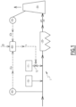
- a smoke treatment installation 1 is shown.
- This installation 1 is for example provided downstream of a household waste incinerator, not shown, whose combustion fumes are sent to the entrance to the installation 1.
- the fumes sent to installation 1 contain mercury, as well as, generally, other pollutants such as acid gases (HCl, SO 2 ), nitrogen oxides, dust and heavy metals other than mercury.
- the mercury contained in the fumes to be treated can be present in various forms, namely elemental, oxidized and particulate.
- Installation 1 includes a gas-solid separator 20 which is based on technology known per se.
- This gas-solid separator 20 is for example a bag filter or an electrofilter.
- the gas-solid separator 20 typically operates at a temperature between 120°C and 250°C, that is to say that the temperature of the fumes entering the gas-solid separator 20 is in the aforementioned range.
- Installation 1 also includes a silo 10 containing an acid gas neutralization reagent, such as lime or sodium bicarbonate.
- This acid gas neutralization reagent is introduced, from the silo 10, into the fumes to be treated upstream of the gas-solid separator 20, in order to neutralize the acid gases present in the fumes to be treated.
- the flow rate of the acid gas neutralization reagent is regulated as a function of the composition of pollutants in the fumes to be treated.
- Installation 1 also includes a silo 11 containing a demercurization reagent, such as those listed in the introductory part of this document.
- This demercurization reagent is introduced, from the silo 11, into the fumes to be treated upstream of the gas-solid separator 20, in order to capture the mercury present in the fumes to be treated.
- the gas-solid separator 20 is adapted to separate the dust and solid reagents, injected into the fumes to be treated from the silos 10 and 11, which the fumes contain when the latter pass through the gas-solid separator. At least part, or even all, of the solids collected by the gas-solid separator 20 is intended to be evacuated from the installation 1, while, where appropriate, the rest of these solids is recycled, by being sent to the fumes to be treated upstream of the gas-solid separator 20.
- Installation 1 is optionally supplemented by other treatment units, placed downstream of the gas-solid separator 20, such as a catalytic denitrification unit for example.
- other equipment such as a fan, a heat exchanger, a reactor or a storage silo for another reagent can be present within the installation 1.
- the fumes treated by the installation 1 are intended to exit the latter via a chimney 30 through which the treated fumes are released into the environment.
- the concentration of mercury in the fumes to be treated that is to say the fumes entering installation 1, can change over time.
- the figure 2 illustrates the concentration, as a function of time, of total mercury vapor (elemental and oxidized) in fumes which come from a household waste incinerator and which are likely to be sent to installation 1 for the purposes of their treatment, in particular their demercurization.
- the mercury concentration is most often around a value of around 100 ⁇ g/Nm 3 but that it experiences, on three occasions, mercury peaks during which the mercury concentration varies in a manner fast and with great intensity, reaching more than 800, even 1000 ⁇ g/Nm 3 , in just a few seconds. Changes in other pollutants, such as acid gases and nitrogen oxides, generally do not show such abrupt variations.
- installation 1 of the figure 1 we will be interested in the way in which this installation 1 is designed to regulate mercury emissions leaving the installation 1, while taking into account the temporal evolution of the mercury concentration in the fumes to be treated entering the the installation, including when this temporal evolution includes one or more mercury peaks. In the absence of such regulation, mercury concentrations in treated smoke could vary by more than two orders of magnitude in a few tens of seconds.
- installation 1 includes two analyzers 40 and 50, as well as a calculator 60.
- the analyzer 40 is adapted to, in real time, determine the concentration of mercury in the fumes upstream of the point of introduction of the demercurization reagent into these fumes, as well as transmit an information signal iCa representative of the value of this concentration, this concentration value being called Ca hereafter. It is not necessary for the information signal iCa emitted by the analyzer 40 to be strictly continuous, in the sense that the concentration values Ca determined by the analyzer 40 are to be provided, via the information signal iCa, at each instant, that is to say at each repetition of a predetermined temporal frequency, preferably worth between thirty seconds and sixty seconds.
- the analyzer 40 is sensitive to one or more forms of mercury present in the fumes to be treated, so that the information signal iCa gives a information on the concentration of total mercury or a form of mercury contained in the fumes to be treated. It is therefore not essential to have knowledge of the speciation of mercury upstream of the point of introduction of the demercurization reagent into the fumes to be treated, because the information signal iCa is provided, as explained subsequently, to be used to monitor the temporal evolution of the mercury concentration in the fumes to be treated, it being noted that the different forms of mercury generally experience the same temporal evolution of their concentration.
- the analyzer 50 is adapted to, in real time, determine the concentration of mercury in the fumes downstream of the gas-solid separator 20, as well as transmit an information signal iCb representative of the value of this concentration, this concentration value being called Cb thereafter.
- This analyzer 50 is preferably placed in the chimney 30. Similar to the analyzer 40, it is not necessary for the information signal iCb emitted by the analyzer 50 to be a strictly continuous signal, in the sense that the values of concentration Cb determined by the analyzer 50 are to be provided, via the information signal iCb, at each instant, that is to say at each repetition of a predetermined temporal frequency, preferably worth approximately three minutes.
- the refresh frequency of the analyzer 50 for determining the concentration value Cb and for transmitting the corresponding information signal iCb is lower than that of the analyzer 40 because, as explained in more detail by the Subsequently, the information signal iCb emitted by the analyzer 50 is intended to provide correction feedback, commonly called “feedback", for the control of mercury emissions in the fumes leaving the installation 1.
- the analyzers 40 and 50 relate to a technology known per se, which is not limiting to the invention.
- the computer 60 is, for its part, adapted to control in real time the dosage of the demercurization reagent introduced, from the silo 11, into the fumes upstream of the point of introduction of this demercurization reagent into the fumes to be treated.
- the computer 60 is designed to execute permanently, that is to say repeatedly at a predetermined temporal frequency, a sequence of calculations, which will be detailed later.
- the computer 60 is connected to the analyzers 40 and 50 by any connection making it possible to transmit the information signals iCa and iCb from the analyzers 40 and 50 to the computer 60.
- the computer 60 is also connected to a member 12 of metering of the flow of demercurization reagent leaving the silo 11, this metering member 12 being for example a solenoid valve.
- this metering member 12 being for example a solenoid valve.
- the embodiment of the connection between the computer 60 and the metering member 12 is immaterial as long as it makes it possible to transmit, from the computer 60 to the metering member 12, a control signal s which is representative of the result of the sequence of calculations executed by the computer 60.
- the computer 60 is also connected to another device, not shown in the figures, providing in real time an information signal iD which is sent to the computer 60 and which is representative of the value of the flow rate of the fumes to be treated, this flow rate value being called D subsequently.
- This information signal iD comes for example from a smoke flow measuring device, placed upstream of the gas-solid separator 20, or from a smoke flow measuring device placed at the chimney 30 or even a device for measuring steam production, or even a system for indirectly evaluating steam production since this is directly correlated to the quantity of fumes processed by the installation 1. More generally, the signal d The information iD provides data to the computer 60 allowing the latter to determine, in particular to calculate, at each instant the flow rate value D representative of the flow rate of the fumes to be treated.
- the embodiment of the calculator 60 is not limiting as long as this calculator 60 is capable, in real time, of processing, in particular digitally, the information signals iCa, iCb and iD by applying the aforementioned sequence of calculations, as well as than to emit the control signal s.
- the computer 60 can be an autonomous calculation unit, in particular in the form of a programmable controller, or belong to a supervision system, in particular a computer system.
- the installation 1 is in established mode and that, after the acid gas neutralization reagent and the demercurization reagent have been introduced into the fumes to be treated upstream of the gas-solid separator 20 from respectively the silo 10 and the silo 11, the fumes to be treated are sent to the gas-solid separator 20.
- the separation carried out by the latter leads to the formation of a filtration cake in the gas-solid separator 20, attached for example to the filtering sleeves of this separator.
- the demercurization reagent is dosed by implementing the following operations.
- an upstream concentration value Ca is determined at each instant for the concentration of mercury in the fumes upstream of the point of introduction of the demercurization reagent into the fumes.
- this determination of the upstream concentration value Ca is carried out, in particular by direct measurement, by the analyzer 40 and this upstream concentration value Ca is supplied to the computer 60 via the information signal iCa.
- a flow rate value D representative of the flow rate of the fumes to be treated is determined at each instant.
- this determination of the flow rate value D is carried out, in particular by calculation, by the computer 60 from the information signal iD.
- a dosage factor called K1
- the dosage factor K1 makes it possible to control a specific dosage of the reagent demercurization and is expressed for example in grams per normal m 3 of smoke.
- the dosage factor K1 is calculated at a low value when the fumes to be treated contain little mercury and is calculated at a high value when the fumes to be treated treat contain a lot of mercury.
- the demercurization process was limited to operations a) and b) described so far, it would be possible to dose the demercurization reagent taking into account the concentration of mercury in the fumes to be treated, but this dosage would be in difficulty during the occurrence of a mercury peak, due to the delayed release of mercury, explained in the introductory part of this document.
- the function f would risk controlling a too rapid decrease and/or premature dosing of the demercurization reagent.
- the other operations of the demercurization process will make it possible to overcome this difficulty, as explained below.
- a quantity of mercury Q by summing, over a predetermined period of time T ending at the considered instant t, the product of the upstream concentration value Ca with the flow rate value D.
- the calculator 60 calculates for this purpose, permanently, the integral, over the period of time T which precedes the instant considered t, the flow of mercury from the fumes to be treated, this mercury flow being calculated by multiplying the upstream concentration value Ca and the flow rate value D.
- This quantity of mercury Q is expressed in mass or molar unit and represents the mercury that the fumes to be treated have entered the installation 1 during the period of time T which precedes the instant considered.
- this quantity of mercury Q is used to estimate the degree of contamination of the gas-solid separator and the other equipment of the installation 1, located downstream of the gas-solid separator 20.
- the time period T is predetermined, being here pre-recorded in the computer 60, and has a value of for example between 15 minutes and 120 minutes.
- the occurrence of a mercury peak is monitored from the upstream concentration value Ca.
- the detection of each mercury peak is here carried out by the calculator 60, using an ad hoc processing, known in itself, applied to the upstream Ca concentration value.
- a Savitzky-Golay filter is applied to the N upstream Ca concentration values determined just before the instant considered, N being greater than or equal to 6.
- the Savitzky-Golay filter is applied to the N upstream concentration values Ca determined just before the instant considered, N being greater than or equal to 3.
- N is greater than or equal to 3: as non-limiting examples, the monitoring algorithm used is based on the arithmetic moving average, the weighted moving average or the exponential moving average , calculated for the N aforementioned values.
- each time a mercury peak occurs the time called t0 when the peak occurs, as well as the value called K0 of the dosage factor K1 at time t0.
- the calculator 60 memorizes the instant t0 and the value K0 calculated for the dosage factor K1.
- a dosage factor is calculated, here by the calculator 60, which is called K2 and which is different from the dosage factor K1, from the value K0 and a function g, which is different from the function f and which is pre-established, here being pre-recorded in the calculator 60.
- the function g decreases with time and is planned so that its decrease over time is all the more slow as the quantity of mercury Q calculated at the instant considered is significant.
- the dosage factor K2 can be obtained by multiplying the value K0 by the result of the function g at the instant considered. Similar to the dosage factor K1, the dosage factor K2 makes it possible to control a specific dosage of the neutralization reagent and is thus expressed for example in kilograms per normal m 3 of fumes. Unlike the dosage factor K1, the decrease in the dosage of the demercurization reagent following a mercury peak is controlled by the dosage factor K2 so as to be slow.
- the specific form for the function g that is to say decreasing over time and with its decrease over time which is all the slower as the quantity of mercury Q calculated at the instant considered is important, allows both to effectively regulate any magnitude of the upstream Ca concentration value during a mercury peak, but also to optimize the consumption of demercurization reagent.
- the mercury peak is intense but short, which means that the quantity of mercury Q provided by the fumes to be treated remains low even if the concentration of mercury in these fumes is high for a short time.
- the dosage factor K1 is brought to a high value and controls a high dosage for the demercurization reagent.
- the dosage factor K1 which decreases rapidly, for example exponentially, in connection with a low value of Y.
- the mercury peak is intense but longer than in the first case, or several mercury peaks follow one another in close succession. The amount of mercury Q and, hence, Y then present high values and a significant quantity of mercury enters installation 1. Once the mercury peak has passed, a diffuse release of mercury in installation 1 occurs, as explained in the introductory part of this document.
- the dosage of the demercurization reagent remains maintained at a high value for a much longer period than in the first case, thanks to the function g which causes the dosage factor K2 to decrease for a long period. and with a low slope since Y has a higher value than in the first case.
- the computer 60 By an operation e), it is planned, at each moment, to compare, here by the calculator 60, the value calculated for the dosage factor K1 and the calculated value of the dosage factor K2, retaining the greater of these two calculated values, called Kf.
- the retained value Kf is equal to the largest of the respective calculated values of the dosage factors K1 and K2.
- This retained value Kf is used to dose the demercurization reagent.
- the computer 60 generates the control signal s from the retained value Kf.
- a downstream concentration value Cb is determined at each instant for the mercury concentration downstream of the gas-solid separator 20, this determination of the downstream concentration value Cb being carried out here, by direct measurement , by the analyzer 50 and being supplied to the computer 60 via the information signal iCb.
- the retained value Kf is, before being used to dose the demercurization reagent, corrected, as the adjusted value Kf', from the downstream concentration value Cb.
- the calculator 60 generates the control signal s from the adjusted value Kf', as indicated schematically on the Figure 3 .
- optional operation f) makes it possible to apply adjustment feedback to the retained value Kf resulting from operation e).
- the correction applied by operation f) is known per se and can in particular be implemented by a PID algorithm (acronym for “proportional, integral, derivative”), here executed by the computer 60.
- a first complement to the demercurization process consists of eliminating the filtration cake as quickly as possible after each mercury peak.
- a declogging sequence to the gas-solid separator 20 is forced so as to eliminate the filtration cake.
- Such an unclogging sequence is known per se and consists in particular of acting mechanically and/or pneumatically on the filtration cake to separate it from the member of the gas-solid separator 20 on which it forms, for example to detach it. sleeves of this separator.
- a second complement to the demercurization process consists of seeking to prevent the mercury present in the filtration cake from being released by the latter due to an excess concentration of acid gases in the fumes passing through the gas-solid separator 20. To do this, it is advantageously provided that, for a predetermined duration, worth for example between 1 and 15 minutes, from the time t0, the acid gas neutralization reagent introduced into the fumes to be treated from the silo is overdosed. 10.
- the dashed line curve on the Figure 4 which is associated with the scale on the left, is the temporal evolution of the upstream concentration value Ca, in other words the temporal evolution of the concentration of mercury in the fumes to be treated, determined by the analyzer 40.
- the peak of the most intense mercury is associated with a value of 1240 ⁇ g/Nm 3 for the upstream Ca concentration value.
- the dotted curve and the solid curve which are both associated with the right scale on the Figure 4 , show the temporal evolution of, respectively, the dosage factor K1 and the retained value Kf.
- the comparison between the curve in dashed lines and the curve in solid lines allows us to see that, during each of the mercury peaks, the retained value Kf is slowed down over time in relation to the dosage factor K1.
- the retained value Kf is controlled by the dosage factor K1
- the retained value Kf is controlled by the dosage factor K2
- the retained value Kf is controlled by the dosage factor K2
- the retained value Kf is controlled by the dosage factor K1
- the retained value Kf is controlled by the dosage factor K1 by controlling a minimum dosage for the demercurization reagent.
Landscapes
- Engineering & Computer Science (AREA)
- Chemical & Material Sciences (AREA)
- Analytical Chemistry (AREA)
- Environmental & Geological Engineering (AREA)
- General Chemical & Material Sciences (AREA)
- Oil, Petroleum & Natural Gas (AREA)
- Chemical Kinetics & Catalysis (AREA)
- Health & Medical Sciences (AREA)
- Biomedical Technology (AREA)
- Mechanical Engineering (AREA)
- General Engineering & Computer Science (AREA)
- Treating Waste Gases (AREA)
Claims (15)
- Quecksilberentfernungsverfahren aus Rauchgasen,wobei zu behandelnde Rauchgase zu einem Gas-Feststoff-Abscheider (20) geleitet werden, wobei ein Quecksilberentfernungsreagenz in die zu behandelnden Rauchgase stromaufwärts von dem Gas-Feststoff-Abscheiders eingeleitet wird,und wobei das Quecksilberentfernungsreagenz dosiert wird, indem zu jedem Zeitpunkt die folgenden Vorgänge durchgeführt werden:a) Bestimmen:- eines stromaufwärtigen Konzentrationswerts (Ca) für die Quecksilberkonzentration in den Rauchgasen stromaufwärts von dem Punkt, an dem das Quecksilberentfernungsreagenz in die zu behandelnden Rauchgase eingeleitet wird, und- eines Durchflusswerts (D), der repräsentativ für den Durchfluss der zu behandelnden Rauchgase ist,b) Berechnen eines ersten Dosierungsfaktors (K1) anhand des stromaufwärtigen Konzentrationswerts (Ca) und einer ersten Funktion (f), die abhängig von dem stromaufwärtigen Konzentrationswert ansteigend ist,c) Berechnen einer Quecksilbermenge (Q), indem über einen vorbestimmten Zeitraum (T), der an dem betrachteten Zeitpunkt endet, das Produkt aus dem stromaufwärtigen Konzentrationswert (Ca) und dem Durchflussmengenwerts (D) summiert wird,d) anhand des stromaufwärtigen Konzentrationswerts (Ca), Überwachen des Auftretens eines Quecksilberspitzenwerts und jedes Mal, wenn ein Quecksilberspitzenwert vorkommt:- Registrieren des als t0 bezeichneten Zeitpunkts, an dem die Spitze vorkommt, sowie des als K0 bezeichneten Werts des ersten Dosierungsfaktors (K1) an dem Zeitpunkt t0, und- zu jedem Zeitpunkt nach dem Zeitpunkt t0, Berechnen eines zweiten Dosierungsfaktors (K2) anhand des Werts K0 und einer zweiten Funktion (g), die mit der Zeit abnimmt und deren zeitlicher Abfall umso langsamer ist, je größer die für den jeweiligen Zeitpunkt berechnete Quecksilbermenge (Q) ist, unde) Vergleichen des berechneten Werts des ersten Dosierungsfaktors (K1) und des berechnete Werts des zweiten Dosierungsfaktors (K2) und Verwenden des größeren (Kf) dieser zwei berechneten Werte, um das Quecksilberentfernungsreagenz zu dosieren.
- Verfahren nach Anspruch 1, wobei die zweite Funktion (g) von der Form exp(-(t-t0)/Y) ist, wobei t der betrachtete Zeitpunkt ist und Y gleich wie die zu diesem Zeitpunkt berechnete Quecksilbermenge (Q) ist, multipliziert mit einer Proportionalitätskonstante.
- Verfahren nach Anspruch 1, wobei die zweite Funktion (g) von der Form 1-((t-t0)/Y) ist, wobei t der betrachtete Zeitpunkt ist und Y gleich wie die zu diesem Zeitpunkt berechnete Quecksilbermenge (Q) ist, multipliziert mit einer Proportionalitätskonstante.
- Verfahren nach Anspruch 1, wobei die zweite Funktion (g) die Form 1/(cosh((t-t0)/Y) hat, wobei t der betrachtete Zeitpunkt ist und Y gleich wie die zu diesem Zeitpunkt berechnete Quecksilbermenge (Q) ist, multipliziert mit einer Proportionalitätskonstante.
- Verfahren nach einem der vorherigen Ansprüche, wobei die erste Funktion (f) zwischen einer minimalen Größe (Cmin) und einer maximalen Größe (Cmax) des Werts der stromaufwärtigen Konzentration (Ca) streng ansteigt und sowohl unterhalb der minimalen Größe als auch oberhalb der maximalen Größe konstant ist.
- Verfahren nach einem der Ansprüche 1 bis 4, wobei die erste Funktion (f) zwischen einem Nullwert des stromaufwärtigen Konzentrationswerts (Ca) und einer maximalen Größe des stromaufwärtigen Konzentrationswerts (Ca) streng ansteigt und über die maximale Größe hinaus konstant ist.
- Verfahren nach einem der Ansprüche 1 bis 4, wobei die erste Funktion (f) treppenförmig ist.
- Verfahren nach einem der vorherigen Ansprüche, wobei das Auftreten einer Messspitze überwacht wird, indem zu jedem Zeitpunkt ein Überwachungsalgorithmus auf die N stromaufwärtigen Konzentrationswerte (Ca) angewendet wird, die unmittelbar vor dem jeweiligen Zeitpunkt bestimmt werden, wobei N größer als oder gleich wie 3 ist.
- Verfahren nach Anspruch 8, wobei der Überwachungsalgorithmus ein Savitzky-Golay-Filter ist.
- Verfahren nach Anspruch 9, wobei der Savitzky-Golay-Filter auf die N stromaufwärtigen Konzentrationswerte (Ca) angewendet wird, die unmittelbar vor dem betrachteten Zeitpunkt bestimmt werden, wobei N größer als oder gleich wie 6 ist.
- Verfahren nach einem der vorherigen Ansprüche, wobei zu jedem Zeitpunkt auch ein stromabwärtiger Konzentrationswert (Cb) für die Quecksilberkonzentration stromabwärts von dem Gas-Feststoff-Abscheider (20) bestimmt wird, und wobei anhand des stromabwärtigen Konzentrationswerts (Cb) der größere (Kf) der zwei berechneten Werte des ersten und des zweiten Dosierungsfaktors (K1, K2) korrigiert wird, bevor dieser zum Dosieren des Quecksilberentfernungsreagenzes verwendet wird.
- Verfahren nach Anspruch 11, wobei der größere (Kf) der zwei berechneten Werte des ersten und des zweiten Dosierungsfaktors (K1, K2) unter Verwendung eines PID-Algorithmus korrigiert wird.
- Verfahren nach einem der vorherigen Ansprüche, wobei die vorbestimmte Zeitperiode (T) zwischen 15 und 120 Minuten beträgt.
- Verfahren nach einem der vorherigen Ansprüche, wobei nach einer vorbestimmten Dauer, die beispielsweise zwischen 1 und 15 Minuten beträgt, ab dem Zeitpunkt t0 ein Filterkuchen aus dem Gas-Feststoff-Abscheider (20) entfernt wird, indem auf den Gas-Feststoff-Abscheider eine erzwungene Verstopfungsentfernungssequenz angewendet wird.
- Verfahren nach einem der vorherigen Ansprüche, wobei über eine vorbestimmte Dauer, die beispielsweise zwischen 1 und 15 Minuten beträgt, ab dem Zeitpunkt t0 ein Reagenz zur Neutralisierung von sauren Gasen, das in die zu behandelnden Rauchgase vor dem Gas-Feststoff-Abscheider (20) eingeführt wird, überdosiert wird.
Applications Claiming Priority (1)
| Application Number | Priority Date | Filing Date | Title |
|---|---|---|---|
| FR2012708A FR3117044B1 (fr) | 2020-12-04 | 2020-12-04 | Procédé de démercurisation de fumées |
Publications (2)
| Publication Number | Publication Date |
|---|---|
| EP4008425A1 EP4008425A1 (de) | 2022-06-08 |
| EP4008425B1 true EP4008425B1 (de) | 2023-09-13 |
Family
ID=74347353
Family Applications (1)
| Application Number | Title | Priority Date | Filing Date |
|---|---|---|---|
| EP21212233.7A Active EP4008425B1 (de) | 2020-12-04 | 2021-12-03 | Verfahren zur entfernung von quecksilber aus rauchgasen |
Country Status (4)
| Country | Link |
|---|---|
| EP (1) | EP4008425B1 (de) |
| DK (1) | DK4008425T3 (de) |
| FI (1) | FI4008425T3 (de) |
| FR (1) | FR3117044B1 (de) |
Family Cites Families (5)
| Publication number | Priority date | Publication date | Assignee | Title |
|---|---|---|---|---|
| ES2446291T3 (es) * | 2008-10-20 | 2014-03-07 | Alstom Technology Ltd | Método y dispositivo para eliminar mercurio de un gas de proceso |
| SG10201709322PA (en) * | 2015-02-18 | 2018-01-30 | Jfe Eng Corp | Apparatus for treatment of waste gas and method for treating the same |
| WO2016193429A1 (en) * | 2015-06-03 | 2016-12-08 | Solvay Sa | Process for treating a gas contaminated by metals or organics compounds using a calcium-phosphate reactant comprising apatite |
| JP6722458B2 (ja) * | 2016-01-22 | 2020-07-15 | 日立造船株式会社 | 飛灰処理設備および飛灰処理のための重金属固定剤の供給方法 |
| CN209997329U (zh) * | 2019-03-20 | 2020-01-31 | 福建龙净环保股份有限公司 | 一种烟气处理系统 |
-
2020
- 2020-12-04 FR FR2012708A patent/FR3117044B1/fr active Active
-
2021
- 2021-12-03 EP EP21212233.7A patent/EP4008425B1/de active Active
- 2021-12-03 DK DK21212233.7T patent/DK4008425T3/da active
- 2021-12-03 FI FIEP21212233.7T patent/FI4008425T3/fi active
Also Published As
| Publication number | Publication date |
|---|---|
| FR3117044A1 (fr) | 2022-06-10 |
| DK4008425T3 (da) | 2023-12-11 |
| FI4008425T3 (fi) | 2023-12-12 |
| EP4008425A1 (de) | 2022-06-08 |
| FR3117044B1 (fr) | 2022-12-16 |
Similar Documents
| Publication | Publication Date | Title |
|---|---|---|
| EP4008425B1 (de) | Verfahren zur entfernung von quecksilber aus rauchgasen | |
| CN107249717A (zh) | 燃烧排气的处理装置 | |
| FR2567999A1 (fr) | Systeme utilisant du gaz d'echappement d'un four electrique pour prechauffer la ferraille entrant dans la fabrication de l'acier | |
| EP3386610A1 (de) | Verfahren zur behandlung von rauchgasen aus einem verbrennungs- oder kalzinierungsofen und anlage zur durchführung solch eines verfahrens | |
| EP1471975B1 (de) | Verfahren und vorrichtung für atemluftproduktion | |
| EP3863751A1 (de) | Verfahren und vorrichtung zur verwaltung einer abgasbehandlungsvorrichtung | |
| EP3002060A1 (de) | Regenerierungsverfahren und anlage eines strukturierten denitrifikationskatalysators | |
| EP4286033B1 (de) | Verfahren zur entfernung von quecksilber aus rauchgasen | |
| EP2397213B1 (de) | Verfahren zur Steuerung des Korrosionsrisikos bei Abgasaufbereitungsverfahren | |
| FR3079758A1 (fr) | Procede de traitement d'air entrant dans et/ou sortant hors d'un espace confine | |
| FR3008322A1 (fr) | Procede d'epuration de fumees de combustion | |
| EP1576999A1 (de) | Modulare und intergrierte Vorrichtung zur Filtration und katalytischen Entstickung von Rauchgasen, Anlage enthaltend eine derartige Vorrichtung und Verfahren zu ihrer Verwendung | |
| EP2465598B1 (de) | Verfahren zur Rauchgasreinigung | |
| WO1995025332A1 (fr) | Procede et installation d'epuration de fumees issues de l'incineration de dechets faiblement radioactifs | |
| JP2017127830A (ja) | 飛灰処理設備および飛灰処理のための重金属固定剤の供給方法 | |
| FR2838161A1 (fr) | Dispositif et procede de purification des emissions d'echappement destines a un moteur a combustion interne | |
| EP2851116B1 (de) | Verfahren zur katalytischen Reinigung von Rauchgasen, die Stickoxide enthalten | |
| BE1021577B1 (fr) | Procede global d'epuration de fumees par voie humide | |
| CN120426573B (zh) | 一种垃圾焚烧烟气处理方法及烟气处理装置 | |
| EP2792401B1 (de) | Kontrollverfahren eines Reaktors mit katalytischer Denitrifikation der Verbrennungsabgase | |
| JPH10296046A (ja) | 排ガス中酸性成分の除去方法 | |
| FR2719499A1 (fr) | Procédé et installation de traitement des fumées de combustion. | |
| EP2719444B1 (de) | Katalytisches Denitrifikationsverfahren für Verbrennungsabgase | |
| FR3159903A1 (fr) | Système de traitement de fumées | |
| EP2292315A1 (de) | Verfahren und Vorrichtung zur Reinigung von Verbrennungsabgasen |
Legal Events
| Date | Code | Title | Description |
|---|---|---|---|
| PUAI | Public reference made under article 153(3) epc to a published international application that has entered the european phase |
Free format text: ORIGINAL CODE: 0009012 |
|
| STAA | Information on the status of an ep patent application or granted ep patent |
Free format text: STATUS: THE APPLICATION HAS BEEN PUBLISHED |
|
| AK | Designated contracting states |
Kind code of ref document: A1 Designated state(s): AL AT BE BG CH CY CZ DE DK EE ES FI FR GB GR HR HU IE IS IT LI LT LU LV MC MK MT NL NO PL PT RO RS SE SI SK SM TR |
|
| STAA | Information on the status of an ep patent application or granted ep patent |
Free format text: STATUS: REQUEST FOR EXAMINATION WAS MADE |
|
| 17P | Request for examination filed |
Effective date: 20221108 |
|
| RBV | Designated contracting states (corrected) |
Designated state(s): AL AT BE BG CH CY CZ DE DK EE ES FI FR GB GR HR HU IE IS IT LI LT LU LV MC MK MT NL NO PL PT RO RS SE SI SK SM TR |
|
| GRAP | Despatch of communication of intention to grant a patent |
Free format text: ORIGINAL CODE: EPIDOSNIGR1 |
|
| STAA | Information on the status of an ep patent application or granted ep patent |
Free format text: STATUS: GRANT OF PATENT IS INTENDED |
|
| RIC1 | Information provided on ipc code assigned before grant |
Ipc: F23J 15/02 20060101ALI20230330BHEP Ipc: F23J 15/00 20060101ALI20230330BHEP Ipc: B01D 53/83 20060101ALI20230330BHEP Ipc: B01D 53/64 20060101ALI20230330BHEP Ipc: B01D 53/34 20060101ALI20230330BHEP Ipc: B01D 53/30 20060101AFI20230330BHEP |
|
| INTG | Intention to grant announced |
Effective date: 20230421 |
|
| P01 | Opt-out of the competence of the unified patent court (upc) registered |
Effective date: 20230516 |
|
| GRAS | Grant fee paid |
Free format text: ORIGINAL CODE: EPIDOSNIGR3 |
|
| GRAA | (expected) grant |
Free format text: ORIGINAL CODE: 0009210 |
|
| STAA | Information on the status of an ep patent application or granted ep patent |
Free format text: STATUS: THE PATENT HAS BEEN GRANTED |
|
| AK | Designated contracting states |
Kind code of ref document: B1 Designated state(s): AL AT BE BG CH CY CZ DE DK EE ES FI FR GB GR HR HU IE IS IT LI LT LU LV MC MK MT NL NO PL PT RO RS SE SI SK SM TR |
|
| REG | Reference to a national code |
Ref country code: CH Ref legal event code: EP |
|
| REG | Reference to a national code |
Ref country code: DE Ref legal event code: R096 Ref document number: 602021005134 Country of ref document: DE |
|
| REG | Reference to a national code |
Ref country code: IE Ref legal event code: FG4D Free format text: LANGUAGE OF EP DOCUMENT: FRENCH |
|
| REG | Reference to a national code |
Ref country code: DK Ref legal event code: T3 Effective date: 20231205 |
|
| REG | Reference to a national code |
Ref country code: FI Ref legal event code: FGE |
|
| REG | Reference to a national code |
Ref country code: NL Ref legal event code: FP Ref country code: SE Ref legal event code: TRGR |
|
| REG | Reference to a national code |
Ref country code: LT Ref legal event code: MG9D |
|
| PG25 | Lapsed in a contracting state [announced via postgrant information from national office to epo] |
Ref country code: GR Free format text: LAPSE BECAUSE OF FAILURE TO SUBMIT A TRANSLATION OF THE DESCRIPTION OR TO PAY THE FEE WITHIN THE PRESCRIBED TIME-LIMIT Effective date: 20231214 |
|
| PG25 | Lapsed in a contracting state [announced via postgrant information from national office to epo] |
Ref country code: RS Free format text: LAPSE BECAUSE OF FAILURE TO SUBMIT A TRANSLATION OF THE DESCRIPTION OR TO PAY THE FEE WITHIN THE PRESCRIBED TIME-LIMIT Effective date: 20230913 Ref country code: NO Free format text: LAPSE BECAUSE OF FAILURE TO SUBMIT A TRANSLATION OF THE DESCRIPTION OR TO PAY THE FEE WITHIN THE PRESCRIBED TIME-LIMIT Effective date: 20231213 Ref country code: LV Free format text: LAPSE BECAUSE OF FAILURE TO SUBMIT A TRANSLATION OF THE DESCRIPTION OR TO PAY THE FEE WITHIN THE PRESCRIBED TIME-LIMIT Effective date: 20230913 Ref country code: LT Free format text: LAPSE BECAUSE OF FAILURE TO SUBMIT A TRANSLATION OF THE DESCRIPTION OR TO PAY THE FEE WITHIN THE PRESCRIBED TIME-LIMIT Effective date: 20230913 Ref country code: HR Free format text: LAPSE BECAUSE OF FAILURE TO SUBMIT A TRANSLATION OF THE DESCRIPTION OR TO PAY THE FEE WITHIN THE PRESCRIBED TIME-LIMIT Effective date: 20230913 Ref country code: GR Free format text: LAPSE BECAUSE OF FAILURE TO SUBMIT A TRANSLATION OF THE DESCRIPTION OR TO PAY THE FEE WITHIN THE PRESCRIBED TIME-LIMIT Effective date: 20231214 |
|
| REG | Reference to a national code |
Ref country code: AT Ref legal event code: MK05 Ref document number: 1610704 Country of ref document: AT Kind code of ref document: T Effective date: 20230913 |
|
| PG25 | Lapsed in a contracting state [announced via postgrant information from national office to epo] |
Ref country code: IS Free format text: LAPSE BECAUSE OF FAILURE TO SUBMIT A TRANSLATION OF THE DESCRIPTION OR TO PAY THE FEE WITHIN THE PRESCRIBED TIME-LIMIT Effective date: 20240113 |
|
| PG25 | Lapsed in a contracting state [announced via postgrant information from national office to epo] |
Ref country code: AT Free format text: LAPSE BECAUSE OF FAILURE TO SUBMIT A TRANSLATION OF THE DESCRIPTION OR TO PAY THE FEE WITHIN THE PRESCRIBED TIME-LIMIT Effective date: 20230913 |
|
| PG25 | Lapsed in a contracting state [announced via postgrant information from national office to epo] |
Ref country code: ES Free format text: LAPSE BECAUSE OF FAILURE TO SUBMIT A TRANSLATION OF THE DESCRIPTION OR TO PAY THE FEE WITHIN THE PRESCRIBED TIME-LIMIT Effective date: 20230913 |
|
| PG25 | Lapsed in a contracting state [announced via postgrant information from national office to epo] |
Ref country code: SM Free format text: LAPSE BECAUSE OF FAILURE TO SUBMIT A TRANSLATION OF THE DESCRIPTION OR TO PAY THE FEE WITHIN THE PRESCRIBED TIME-LIMIT Effective date: 20230913 Ref country code: RO Free format text: LAPSE BECAUSE OF FAILURE TO SUBMIT A TRANSLATION OF THE DESCRIPTION OR TO PAY THE FEE WITHIN THE PRESCRIBED TIME-LIMIT Effective date: 20230913 Ref country code: IS Free format text: LAPSE BECAUSE OF FAILURE TO SUBMIT A TRANSLATION OF THE DESCRIPTION OR TO PAY THE FEE WITHIN THE PRESCRIBED TIME-LIMIT Effective date: 20240113 Ref country code: ES Free format text: LAPSE BECAUSE OF FAILURE TO SUBMIT A TRANSLATION OF THE DESCRIPTION OR TO PAY THE FEE WITHIN THE PRESCRIBED TIME-LIMIT Effective date: 20230913 Ref country code: EE Free format text: LAPSE BECAUSE OF FAILURE TO SUBMIT A TRANSLATION OF THE DESCRIPTION OR TO PAY THE FEE WITHIN THE PRESCRIBED TIME-LIMIT Effective date: 20230913 Ref country code: AT Free format text: LAPSE BECAUSE OF FAILURE TO SUBMIT A TRANSLATION OF THE DESCRIPTION OR TO PAY THE FEE WITHIN THE PRESCRIBED TIME-LIMIT Effective date: 20230913 Ref country code: PT Free format text: LAPSE BECAUSE OF FAILURE TO SUBMIT A TRANSLATION OF THE DESCRIPTION OR TO PAY THE FEE WITHIN THE PRESCRIBED TIME-LIMIT Effective date: 20240115 Ref country code: SK Free format text: LAPSE BECAUSE OF FAILURE TO SUBMIT A TRANSLATION OF THE DESCRIPTION OR TO PAY THE FEE WITHIN THE PRESCRIBED TIME-LIMIT Effective date: 20230913 |
|
| PG25 | Lapsed in a contracting state [announced via postgrant information from national office to epo] |
Ref country code: PL Free format text: LAPSE BECAUSE OF FAILURE TO SUBMIT A TRANSLATION OF THE DESCRIPTION OR TO PAY THE FEE WITHIN THE PRESCRIBED TIME-LIMIT Effective date: 20230913 |
|
| REG | Reference to a national code |
Ref country code: DE Ref legal event code: R097 Ref document number: 602021005134 Country of ref document: DE |
|
| PLBE | No opposition filed within time limit |
Free format text: ORIGINAL CODE: 0009261 |
|
| STAA | Information on the status of an ep patent application or granted ep patent |
Free format text: STATUS: NO OPPOSITION FILED WITHIN TIME LIMIT |
|
| 26N | No opposition filed |
Effective date: 20240614 |
|
| PG25 | Lapsed in a contracting state [announced via postgrant information from national office to epo] |
Ref country code: LU Free format text: LAPSE BECAUSE OF NON-PAYMENT OF DUE FEES Effective date: 20231203 |
|
| PG25 | Lapsed in a contracting state [announced via postgrant information from national office to epo] |
Ref country code: MC Free format text: LAPSE BECAUSE OF FAILURE TO SUBMIT A TRANSLATION OF THE DESCRIPTION OR TO PAY THE FEE WITHIN THE PRESCRIBED TIME-LIMIT Effective date: 20230913 |
|
| REG | Reference to a national code |
Ref country code: BE Ref legal event code: MM Effective date: 20231231 |
|
| PG25 | Lapsed in a contracting state [announced via postgrant information from national office to epo] |
Ref country code: MC Free format text: LAPSE BECAUSE OF FAILURE TO SUBMIT A TRANSLATION OF THE DESCRIPTION OR TO PAY THE FEE WITHIN THE PRESCRIBED TIME-LIMIT Effective date: 20230913 Ref country code: LU Free format text: LAPSE BECAUSE OF NON-PAYMENT OF DUE FEES Effective date: 20231203 |
|
| REG | Reference to a national code |
Ref country code: IE Ref legal event code: MM4A |
|
| PG25 | Lapsed in a contracting state [announced via postgrant information from national office to epo] |
Ref country code: IE Free format text: LAPSE BECAUSE OF NON-PAYMENT OF DUE FEES Effective date: 20231203 |
|
| PG25 | Lapsed in a contracting state [announced via postgrant information from national office to epo] |
Ref country code: BE Free format text: LAPSE BECAUSE OF NON-PAYMENT OF DUE FEES Effective date: 20231231 |
|
| PG25 | Lapsed in a contracting state [announced via postgrant information from national office to epo] |
Ref country code: SI Free format text: LAPSE BECAUSE OF FAILURE TO SUBMIT A TRANSLATION OF THE DESCRIPTION OR TO PAY THE FEE WITHIN THE PRESCRIBED TIME-LIMIT Effective date: 20230913 |
|
| PG25 | Lapsed in a contracting state [announced via postgrant information from national office to epo] |
Ref country code: SI Free format text: LAPSE BECAUSE OF FAILURE TO SUBMIT A TRANSLATION OF THE DESCRIPTION OR TO PAY THE FEE WITHIN THE PRESCRIBED TIME-LIMIT Effective date: 20230913 Ref country code: IE Free format text: LAPSE BECAUSE OF NON-PAYMENT OF DUE FEES Effective date: 20231203 Ref country code: BE Free format text: LAPSE BECAUSE OF NON-PAYMENT OF DUE FEES Effective date: 20231231 |
|
| PG25 | Lapsed in a contracting state [announced via postgrant information from national office to epo] |
Ref country code: BG Free format text: LAPSE BECAUSE OF FAILURE TO SUBMIT A TRANSLATION OF THE DESCRIPTION OR TO PAY THE FEE WITHIN THE PRESCRIBED TIME-LIMIT Effective date: 20230913 |
|
| PG25 | Lapsed in a contracting state [announced via postgrant information from national office to epo] |
Ref country code: BG Free format text: LAPSE BECAUSE OF FAILURE TO SUBMIT A TRANSLATION OF THE DESCRIPTION OR TO PAY THE FEE WITHIN THE PRESCRIBED TIME-LIMIT Effective date: 20230913 |
|
| PG25 | Lapsed in a contracting state [announced via postgrant information from national office to epo] |
Ref country code: CY Free format text: LAPSE BECAUSE OF FAILURE TO SUBMIT A TRANSLATION OF THE DESCRIPTION OR TO PAY THE FEE WITHIN THE PRESCRIBED TIME-LIMIT; INVALID AB INITIO Effective date: 20211203 |
|
| PG25 | Lapsed in a contracting state [announced via postgrant information from national office to epo] |
Ref country code: TR Free format text: LAPSE BECAUSE OF FAILURE TO SUBMIT A TRANSLATION OF THE DESCRIPTION OR TO PAY THE FEE WITHIN THE PRESCRIBED TIME-LIMIT Effective date: 20230913 |
|
| PGFP | Annual fee paid to national office [announced via postgrant information from national office to epo] |
Ref country code: NL Payment date: 20251127 Year of fee payment: 5 |
|
| REG | Reference to a national code |
Ref country code: CH Ref legal event code: U11 Free format text: ST27 STATUS EVENT CODE: U-0-0-U10-U11 (AS PROVIDED BY THE NATIONAL OFFICE) Effective date: 20260101 |
|
| REG | Reference to a national code |
Ref country code: CH Ref legal event code: R18 Free format text: ST27 STATUS EVENT CODE: U-0-0-R10-R18 (AS PROVIDED BY THE NATIONAL OFFICE) Effective date: 20260106 |
|
| PGFP | Annual fee paid to national office [announced via postgrant information from national office to epo] |
Ref country code: GB Payment date: 20251229 Year of fee payment: 5 |
|
| PGFP | Annual fee paid to national office [announced via postgrant information from national office to epo] |
Ref country code: IT Payment date: 20251210 Year of fee payment: 5 Ref country code: FI Payment date: 20251124 Year of fee payment: 5 Ref country code: DK Payment date: 20251127 Year of fee payment: 5 |
|
| PGFP | Annual fee paid to national office [announced via postgrant information from national office to epo] |
Ref country code: FR Payment date: 20251114 Year of fee payment: 5 |
|
| PGFP | Annual fee paid to national office [announced via postgrant information from national office to epo] |
Ref country code: SE Payment date: 20251218 Year of fee payment: 5 |
|
| PGFP | Annual fee paid to national office [announced via postgrant information from national office to epo] |
Ref country code: CZ Payment date: 20251203 Year of fee payment: 5 |
|
| PGFP | Annual fee paid to national office [announced via postgrant information from national office to epo] |
Ref country code: DE Payment date: 20251231 Year of fee payment: 5 |
|
| PGFP | Annual fee paid to national office [announced via postgrant information from national office to epo] |
Ref country code: CH Payment date: 20260101 Year of fee payment: 5 |