EP4285758B1 - Aerosolerzeugungsvorrichtung - Google Patents
Aerosolerzeugungsvorrichtung Download PDFInfo
- Publication number
- EP4285758B1 EP4285758B1 EP21922642.0A EP21922642A EP4285758B1 EP 4285758 B1 EP4285758 B1 EP 4285758B1 EP 21922642 A EP21922642 A EP 21922642A EP 4285758 B1 EP4285758 B1 EP 4285758B1
- Authority
- EP
- European Patent Office
- Prior art keywords
- aerosol
- sidewall
- heating
- airflow channel
- generating device
- Prior art date
- Legal status (The legal status is an assumption and is not a legal conclusion. Google has not performed a legal analysis and makes no representation as to the accuracy of the status listed.)
- Active
Links
Images


Classifications
-
- A—HUMAN NECESSITIES
- A24—TOBACCO; CIGARS; CIGARETTES; SIMULATED SMOKING DEVICES; SMOKERS' REQUISITES
- A24F—SMOKERS' REQUISITES; MATCH BOXES; SIMULATED SMOKING DEVICES
- A24F40/00—Electrically operated smoking devices; Component parts thereof; Manufacture thereof; Maintenance or testing thereof; Charging means specially adapted therefor
- A24F40/40—Constructional details, e.g. connection of cartridges and battery parts
- A24F40/48—Fluid transfer means, e.g. pumps
- A24F40/485—Valves; Apertures
-
- A—HUMAN NECESSITIES
- A24—TOBACCO; CIGARS; CIGARETTES; SIMULATED SMOKING DEVICES; SMOKERS' REQUISITES
- A24F—SMOKERS' REQUISITES; MATCH BOXES; SIMULATED SMOKING DEVICES
- A24F40/00—Electrically operated smoking devices; Component parts thereof; Manufacture thereof; Maintenance or testing thereof; Charging means specially adapted therefor
- A24F40/40—Constructional details, e.g. connection of cartridges and battery parts
- A24F40/48—Fluid transfer means, e.g. pumps
-
- A—HUMAN NECESSITIES
- A24—TOBACCO; CIGARS; CIGARETTES; SIMULATED SMOKING DEVICES; SMOKERS' REQUISITES
- A24F—SMOKERS' REQUISITES; MATCH BOXES; SIMULATED SMOKING DEVICES
- A24F40/00—Electrically operated smoking devices; Component parts thereof; Manufacture thereof; Maintenance or testing thereof; Charging means specially adapted therefor
- A24F40/20—Devices using solid inhalable precursors
-
- A—HUMAN NECESSITIES
- A24—TOBACCO; CIGARS; CIGARETTES; SIMULATED SMOKING DEVICES; SMOKERS' REQUISITES
- A24F—SMOKERS' REQUISITES; MATCH BOXES; SIMULATED SMOKING DEVICES
- A24F40/00—Electrically operated smoking devices; Component parts thereof; Manufacture thereof; Maintenance or testing thereof; Charging means specially adapted therefor
- A24F40/40—Constructional details, e.g. connection of cartridges and battery parts
- A24F40/46—Shape or structure of electric heating means
- A24F40/465—Shape or structure of electric heating means specially adapted for induction heating
Definitions
- the present disclosure relates to the field of aerosol-generating technologies, and in particular, to an aerosol-generating device.
- the aerosol-generating device of the "heat-not-burn” type generates aerosols by heating and baking different forms of aerosol-generating substrates (such as grass leaf materials), and transmits the aerosol to a user for inhalation.
- the aerosol-generating substrate is heated only at a lower temperature (200°C-400°C), does not burn and does not generate an open flame, and effectively avoids generation of harmful substances caused by the aerosol-generating substrate.
- electromagnetic induction heating or resistive material heating is commonly used in the "heat-not-burn" aerosol-generating device.
- the electromagnetic induction heating is as follows: A coil is disposed around a heating member that contains the aerosol-generating substrate, the heating member heats up by means of electromagnetic induction, heat is conducted to the aerosol-generating substrate, and baking and heating are performed on the aerosol-generating substrate.
- the aerosol-generating substrate is usually formed into a close fit with the heating member for baking and heating.
- the heating member is able to reach a very high temperature at a moment, and the outer periphery of the aerosol-generating substrate that is in direct contact with the heating member is able to easily reach a high temperature.
- inner heat transfer efficiency of the aerosol-generating substrate is low, baking of the inner aerosol-generating substrate is insufficient, and temperature distribution of the inner and outer periphery of the aerosol-generating substrate is uneven.
- the aerosol-generating device is able to resolve the problem that the inner and outer peripheral temperatures are uneven when the aerosol-generating substrate is heated.
- the aerosol-generating device includes a heating base and a heating member.
- the heating base includes a heating cavity; and the heating member is configured to accommodate and heat an aerosol-generating substrate, the heating member is disposed in the heating cavity;
- the heating member includes a first sidewall, and a first airflow channel is formed between the first sidewall and the inner surface of the heating cavity; and at least one protrusion is disposed on the inner surface of the first sidewall, the protrusion makes a second airflow channel formed between the first sidewall and the aerosol-generating substrate, and both the first airflow channel and the second airflow channel are led from the outside of the aerosol-generating device to the bottom of the heating cavity.
- the ratio of the surface area of the protrusion for contacting the aerosol-generating substrate to the inner surface area of the first sidewall is 5%-15%.
- the height of the protrusion is 2 mm-5 mm.
- the first sidewall is disposed in a ring shape.
- the at least one protrusion is spirally disposed on the inner surface of the first sidewall; or the at least one protrusion is a plurality of strip-shaped protrusions disposed on the inner surface of the first sidewall at intervals in the circumferential direction; or the at least one protrusion is a plurality of arcuate protrusions disposed on the inner surface of the first sidewall at intervals in the circumferential direction; or the at least one protrusion is a plurality of dotted protrusions distributed in an array on the inner surface of the first sidewall; or the at least one protrusion is a plurality of annular protrusions disposed on the inner surface of the first sidewall at intervals in the axial direction, and each annular protrusion includes a groove or a through hole.
- a part of the first sidewall portion protrudes inwards to form the protrusion.
- the first sidewall is disposed in a ring shape, and the heating member is disposed coaxially with the heating base.
- the heating base includes a second sidewall, a first limiting member is disposed between the first sidewall and the second sidewall, and the first limiting member spaces the first sidewall from the second sidewall to form the first airflow channel between the first sidewall and the inner surface of the heating cavity.
- the outer surface of the first sidewall protrudes to form the first limiting member; and/or the inner surface of the second sidewall protrudes to form the first limiting member.
- the first limiting member includes an air hole to enable air to flow through the first airflow channel to the bottom of the aerosol-generating substrate.
- the heating base includes a second sidewall and a bottom wall, and the second sidewall surrounds to form the heating cavity; and a third airflow channel is formed between the bottom wall and the aerosol-generating substrate, and the third airflow channel communicates with the first airflow channel and the second airflow channel.
- a first limiting member is disposed between the first sidewall and the second sidewall, and the first limiting member is configured to limit the radial position of the heating member to separate the first sidewall and the second sidewall.
- the first sidewall abuts against the bottom wall, and the end of the first sidewall close to the bottom wall has an opening for the third airflow channel to communicate with the first airflow channel.
- the bottom wall or the first sidewall or the second sidewall is provided with a second limiting member; and the second limiting member spaces the aerosol-generating substrate from the bottom wall to form the third airflow channel.
- a fourth opening is formed at the end of the heating member close to the bottom of the heating cavity, the height of the second limiting member is higher than or equal to the distance between the fourth opening and the bottom of the heating cavity.
- the first limiting member includes an air hole to enable air to flow through the first airflow channel to the bottom of the aerosol-generating substrate.
- a first airflow channel and a second airflow channel are formed on two sides of a heating member.
- a protrusion in the second airflow channel changes a heat transfer mode of the heating member for heating the aerosol-generating substrate from heat conduction to a combination of heat conduction and heat convection, in which heat convection takes a main heat transfer manner.
- Heat transfer efficiency of heat convection is lower than heat transfer efficiency of heat conduction, and therefore, the heat transfer rate of the heat from the heating member to the outer periphery of the aerosol-generating substrate is able to be effectively slowed down.
- a cold airflow passes through the first airflow channel and the second airflow channel, such that the heating rate of air in the first airflow channel and the second airflow channel is able to be slower, and the heat transfer rate of the heating member to the outer periphery of the aerosol-generating substrate is close to the heat transfer rate of the outer periphery of the aerosol-generating substrate to the inside of the aerosol-generating substrate. Therefore, the temperature difference between the inner and outer periphery of the aerosol-generating substrate is effectively reduced, thereby resolving the problem of uneven temperature distribution between the inner and outer periphery of the aerosol-generating substrate during heating.
- first”, “second”, and “third” in the present disclosure are merely intended for a purpose of description, and shall not be understood as an indication or implication of relative importance or implicit indication of the number of indicated technical features. Therefore, features defining “first”, “second”, and “third” may explicitly or implicitly include at least one feature.
- “plurality of” means at least two, such as two and three unless it is specifically defined otherwise. All directional indications (for example, up, down, left, right, front, back%) in the embodiments of the present disclosure are only used for explaining relative position relationships, movement situations, or the like between the various components in a specific posture (as shown in the accompanying drawings). If the specific posture changes, the directional indications change accordingly.
- the terms “include”, “have”, and any variant thereof are intended to cover a non-exclusive inclusion.
- a process, method, system, product, or device that includes a series of steps or units is not limited to the listed steps or units, but further optionally includes a step or unit that is not listed, or further optionally includes another step or component that is intrinsic to the process, method, product, or device.
- Embodiments mentioned in the specification means that particular features, structures, or characteristics described with reference to the embodiments may be included in at least one embodiment of the present disclosure.
- a term appearing at different positions of this specification may not refer to the same embodiment or an independent or alternative embodiment that is mutually exclusive with some embodiments.
- a person skilled in the art explicitly or implicitly understands that the embodiments described in the specification may be combined with other embodiments.
- an aerosol-generating substrate has a housing.
- the outside is provided with a paper package, but to make the description of the embodiments more simplified, an aerosol-generating substrate described below generally refers to an aerosol-generating substrate including a housing.
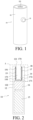
- FIG. 1 is a structural schematic view of an aerosol-generating device 10 according to the present disclosure
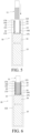
- FIG. 2 is a cross-sectional structural schematic view of the aerosol-generating device 10 shown in FIG. 1
- FIG. 3 is an enlarged structural schematic view of part A shown in FIG. 2
- FIG. 4 is a structural schematic view of an aerosol-generating device 10 and an aerosol-generating substrate 11 assembled together.
- the aerosol-generating device 10 is provided.
- the aerosol-generating device 10 may be configured to heat and bake the aerosol-generating substrate 11 and generate an aerosol for a user to inhale.
- the aerosol-generating device 10 includes a housing 12 and a heating switch 13.
- the heating switch 13 is disposed on the outer surface of the housing 12, and is configured to control on and off of the aerosol-generating device 10.
- Various components of the aerosol-generating device 10 are disposed in the housing 12.
- the shape of the housing 12 is cylindrical. In other embodiments, the housing 12 may also be other shapes.
- the housing 12 may be made of the same material, or may be made of multiple materials.
- the housing 12 includes a plastic outer layer and a metal inner layer, and the user is only able to contact the plastic outer layer when using it.
- Heat generated inside the aerosol-generating device 10 is evenly distributed in the metal inner layer due to the property of rapid heat conduction of the metal, so as to prevent scalding hands of the user as a result of the heated plastic outer layer being touched by the user, and is able to further prevent softening of the plastic outer layer.
- the aerosol-generating device 10 further includes an atomizer 14, a battery assembly 15, and a controller 16.
- the atomizer 14 is electrically connected to the battery assembly 15.
- a top of the housing 12 has a first opening 121
- the inside of the housing 12 has a mounting cavity 122
- both the atomizer 14 and the battery assembly 15 are disposed in the mounting cavity 122
- the atomizer 14 is disposed on one side of the battery assembly 15 close to the first opening 121.
- the atomizer 14 is configured to heat and bake the aerosol-generating substrate 11 and generate an aerosol
- the battery assembly 15 is configured to provide a power supply for the atomizer 14.
- the atomizer 14 includes a heating base 17, a coil 18, and a heating member 19.
- the controller 16 is disposed on one side of the battery assembly 15 close to the first opening 121, and the controller 16 is electrically connected to the coil 18, the heating switch 13, and the battery assembly 15.
- the controller 16 is configured to control start and stop of heating of the coil 18 and the heating member 19 by means of electromagnetic induction, and is able to control parameters such as a heating power and a temperature.
- the heating switch 13 of the housing 12 may be pressed.
- the battery assembly 15 is controlled to supply power to the coil 18, such that the coil 18 and the heating member 19 heat the aerosol-generating substrate by means of electromagnetical induction.
- the controller 16 When the user presses the heating switch 13 of the housing 12 again, the controller 16 receives a request of stop using from the user, and controls the battery assembly 15 to stop supplying power to the coil 18, then the coil 18 stops working.
- the controller 16 further has other functions, and details are not described herein.
- the heating base 17 is configured to fasten the aerosol-generating substrate 11.
- the heating base 17 is disposed at one end of the mounting cavity 122 close to the first opening 121, and the heating base 17 has a bottom wall 171 and a second sidewall 172.
- the second sidewall 172 of the heating base 17 is arranged in a ring shape and is shaped as a cylinder, the second sidewall 172 is disposed at one end of the bottom wall 171 close to the first opening 121, and the second sidewall 172 and the bottom wall 171 of the heating base 17 surround to form the heating cavity 173.
- the thickness of the bottom wall 171 is greater than the thickness of the second sidewall 172, such that the structural strength of the heating base 17 is higher.
- the second sidewall 172 and the bottom wall 171 are integrally formed, and the material of the second sidewall 172 and the bottom wall 171 may be a thermally conductive material such as a metal or an alloy.
- a top of the second sidewall 172 of the heating base 17 abuts against a top of the housing 12, and the heating base 17 is coaxially disposed with the housing 12.
- One end of the second sidewall 172 close to the first opening 121 has a second opening 174, and the caliber of the second opening 174 is greater than or equal to the caliber of the first opening 121. Therefore, the heating base 17 separates the mounting cavity 122 from the heating cavity 173, and the heating cavity 173 communicates with the outside of the aerosol-generating device 10 through the second opening 174 and the first opening 121.
- the caliber of the second opening 174 is the same as the caliber of the first opening 121 and less than the inner diameter of the second sidewall 172, and shapes of both the second opening 174 and the first opening 121 are circular.
- the heating base 17 is not limited to the structure described in the present embodiment.
- the coil 18 is configured to heat the aerosol-generating substrate 11.
- the coil 18 is sleeved on the outer periphery of the second sidewall 172 of the heating base 17, so as to heat the aerosol-generating substrate 11 in the heating member 19.
- the coil 18 is a spirally wound coil, and a changing magnetic field is generated after the coil is energized, forming an eddy current which penetrates the metal heating member 19, such that the metal heating member 19 heats up and heats the aerosol-generating substrate 11.
- other heating manners for example, a resistance wire, may be used to heat the aerosol-generating substrate 11.
- the heating member 19 is disposed in the heating cavity 173.
- the heating member 19 includes a first sidewall 191. Further, the first sidewall 191 of the heating member 19 is annularly arranged, and one end of the first sidewall 191 close to the second opening 174 has a third opening 192. Therefore, the inside of the heating member 19 communicates with the heating cavity 173, and communicates with the outside of the aerosol-generating device 10.
- the heating member 19 is configured to accommodate and heat the aerosol-generating substrate 11, and the aerosol-generating substrate 11 may be disposed inside the heating member 19.
- the aerosol-generating substrate 11 is inserted from the first opening 121 of the aerosol-generating device 10, and is disposed inside a heat conductive body after successively passing through the second opening 174 of the heating base 17 and the third opening 192 of the heating member 19.
- the shape of the heating member 19 may be cylindrical, or certainly, may be other shapes, such as a cylinder-like shape or a cube.
- the heating member 19 is coaxial with the heating base 17. Therefore, the coil 18 is able to evenly heat the outer periphery of the first sidewall 191, and is further able to evenly heat the outer periphery of the aerosol-generating substrate 11.
- FIG. 7 is a schematic view of a flow path of an airflow in the aerosol-generating device 10 according to the present disclosure.
- at least one protrusion 193 is provided on the inner surface of the first sidewall 191 of the heating member 19. A part of the surface of the protrusion 193 is in contact with the outer periphery of the aerosol-generating substrate 11, and heat is transferred to the aerosol-generating substrate 11 in a heat conduction manner.
- the protrusion 193 of the first sidewall 191 is able to form a gap between the aerosol-generating substrate 11 and the inner surface of the first sidewall 191, and form a second airflow channel 20.
- the second airflow channel 20 is led from the outside of the aerosol-generating device 10 to the bottom of the heating cavity 173, such that air flows from the third opening 192 into the second airflow channel 20, flows to the bottom of the heating cavity 173 through the second airflow channel 20, and finally flows to one end of the aerosol-generating substrate 11 away from the third opening 192.
- the airflow flows through the protrusion 193 on the first sidewall 191
- the airflow flows from two sides of the protrusion 193 to the bottom of the aerosol-generating substrate 11.
- the first airflow channel 21 is led from the outside of the aerosol-generating device 10 to the bottom of the heating cavity 173, such that air flows from the second opening 174 into the second airflow channel 20, flows to the bottom of the heating cavity 173 through the second airflow channel 20, and finally flows to one end of the aerosol-generating substrate 11 away from the third opening 192.
- the second airflow channel 20 and the protrusion 193 are disposed to change the heat transfer mode of the heating member 19 to the aerosol-generating substrate 11 from heat conduction to a combination of heat conduction and heat convection, and heat convection is the main heat transfer manner.
- Heat transfer efficiency of heat convection is lower than heat transfer efficiency of heat conduction, and therefore, a heat transfer rate of the heat from the heating member 19 to the outer periphery of the aerosol-generating substrate 11 is effectively slowed down. Therefore, the heat transfer rate of the heating member 19 to the outer periphery of the aerosol-generating substrate 11 is close to the heat transfer rate of the outer periphery of the aerosol-generating substrate 11 to the inside of the aerosol-generating substrate 11.
- the temperature difference between the inner and outer periphery of the aerosol-generating substrate 11 is effectively reduced, thereby resolving the problem of uneven temperature between the inner and outer periphery of the aerosol-generating substrate 11 during heating.
- the first airflow channel 21 and the second airflow channel 20 are disposed on two sides of the heating member 19, such that the heating rate of air in the first airflow channel 21 and in the second airflow channel 20 is slower.
- the airflow flows from the outside of the aerosol-generating device 10 through the first airflow channel 21 and the second airflow channel 20 to the bottom of the heating cavity 173, and heat in the first airflow channel 21 and the second airflow channel 20 is taken away, such that heat generated by the heating member 19 and heat radiated by the first sidewall 191 on the inner surface of the heating base 17 are reduced.
- the heat transfer rate of the heat to the outer periphery of the aerosol-generating substrate 11 is slower, the temperature difference between the outer periphery of the aerosol-generating substrate 11 and the inside of the aerosol-generating substrate 11 is smaller, and uniformity of temperature distribution between the inner periphery and the outer periphery of the aerosol-generating substrate 11 is better, thereby resolving the problem of uneven temperature between the inner and outer periphery of the aerosol-generating substrate during heating.
- the housing 12 of the aerosol-generating device 10 is able to be insulated.
- first airflow channel 21 and the second airflow channel 20 are disposed on two sides of the heating member 19, such that flow of the airflow in the heating cavity 173 is able to be increased, and the airflow may simultaneously flow from two sides of the first sidewall 191. Therefore, inhalation resistance inside the aerosol-generating device 10 is smaller, and the user inhales more easily when using the aerosol-generating device 10.
- the protrusion 193 is able to further reduce a contact area between the heating member 19 and the aerosol-generating substrate 11, and an aerosol condensate is less likely to adhere to the first sidewall 191, thereby reducing adhesion of stains on the heating member 19.
- the arrangement of the protrusion 193 is also able to reduce a contact area between the heating member 19 and the paper outer wall, so as to prevent the paper outer wall from being baked and pasted due to overheating, and prevent a pungent smell from forming, which improves user experience.
- the ratio of the surface area of the protrusion 193 in contact with the aerosol-generating substrate 11 to the inner surface area of the first sidewall 191 is 5%-15%.
- the ratio may be 5%, 10%, or 15%.
- the surface of the protrusion 193 in contact with the aerosol-generating substrate 11 means: the surface of one end of the protrusion 193 in contact with the surface of the aerosol-generating substrate 11 when the aerosol-generating substrate 11 is disposed in the heating member 19.
- the smaller the area ratio of the contact surface to the inner surface of the first sidewall 191 is, the smaller the heat transfer area of the heat conduction is, in the common heat transfer manner, the smaller the proportion of heat conduction to heat convection is.
- the heat transfer rate of the heating member 19 toward the outer periphery of the aerosol-generating substrate 11 is gradually similar to the heat transfer rate of the outer periphery of the aerosol-generating substrate 11 toward the inside of the aerosol-generating substrate 11, and the temperature difference between the inner and outer periphery of the aerosol-generating substrate 11 is reduced, thereby effectively resolving the problem of uneven temperature distribution on the inner periphery and outer periphery of the aerosol-generating substrate 11 during heating.
- the heat transfer rate inside the aerosol-generating substrate 11 is greater than the heat transfer rate between the heating member 19 and the outer periphery of the aerosol-generating substrate 11, and the temperature difference between the inside and outside of the aerosol-generating substrate 11 tends to be 0 after heating for a period of time, and the inner and outer periphery temperature are more evenly distributed.
- the area ratio of the contact surface to the inner surface of the first sidewall 191 may not be too high or too low, and when the area ratio is too high, the proportion of heat convection in the common heat transfer manner is reduced, and the heat transfer rate of the heat to the aerosol-generating substrate 11 is not able to be reduced. Too low an area ratio makes the proportion of heat conduction too low and the heating effect is not good.
- the protrusion 193 may be a bump, and the bump is disposed on the inner surface of the first sidewall 191.
- the material of the bump may be the same as the material of the first sidewall 191, and the bump and the first sidewall 191 are integrally formed.
- the bump may alternatively be made of a material different from the material of the first sidewall 191, and the bump may be made of a material with relatively poor heat conductivity. Therefore, when the heat is transferred from the protrusion 193 to the aerosol-generating substrate 11 in the heat conduction manner, As heat conductivity of the bump is relatively poor, the speed of heat conduction may be reduced, such that the heat transfer rate of the heating member 19 to the outer periphery of the aerosol-generating substrate 11 and the heat transfer rate of the outer periphery of the aerosol-generating substrate 11 to the inside of the aerosol-generating substrate 11 are closer to each other. Therefore, the temperature difference between the inner and outer periphery of the aerosol-generating substrate 11 is effectively reduced, and the temperature of the inner and outer periphery of the aerosol-generating substrate 11 is more uniform.
- the maximum height of the protrusion 193 is 2 mm-5 mm.
- the maximum height of the protrusion 193 refers to the maximum height at which the protrusion 193 protrudes relative to the inner surface of the first sidewall 191.
- the maximum height of the protrusion 193 may be adjusted to adjust the width of the gap between the heating member 19 and the aerosol-generating substrate 11, so as to control the size of the airflow in the second airflow channel 20, thereby achieving the effect of adjusting the inhalation resistance.
- the plurality of protrusions 193 may be spirally disposed on the inner surface of the first sidewall 191.
- the plurality of protrusions 193 may be circumferentially distributed on the inner surface of the first sidewall 191, and/or the plurality of protrusions 193 are axially distributed on the inner surface of the first sidewall 191.
- the plurality of protrusions 193 may be evenly distributed along the circumferential direction at intervals, and the plurality of protrusions 193 are in contact with the peripheral edge of the aerosol-generating substrate 11, so as to limit the aerosol-generating substrate 11.
- the shape of the protrusion 193 may be a regular shape, such as a strip shape, a dot shape, or a ring shape, or may be an irregular shape.
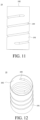
- four types of heating members 19 with different shapes and distributed protrusions 193 are shown in FIG. 8 to FIG. 11 .
- the protrusion 193 in FIG. 8 is strip-shaped, and the strip-shaped protrusion 193 extends from the third opening 192 to one end facing away from the third opening 192, that is, extends from the top of the first sidewall 191 to the bottom.
- the plurality of strip-shaped protrusions 193 are distributed on the inner surface of the first sidewall 191 at intervals in the circumferential direction. Specifically, the four strip-shaped protrusions 193 are evenly circumferentially distributed on the inner surface of the first sidewall 191.
- the extending direction of the strip-shaped protrusion 193 may be parallel to the axial direction of the heating member 19.
- the protrusion 193 in FIG. 9 is arcuate, one end of the arcuate protrusion 193 extends in the circumferential direction to another end, and a plurality of arcuate protrusions 193 are distributed on the inner surface of the first sidewall 191 at intervals in the circumferential direction. Specifically, the four arcuate protrusions 193 are evenly circumferentially distributed on the inner surface of the first sidewall 191.
- the distribution of the protrusions 193 shown in FIG. 9 may also be considered as an annular protrusion 193 being broken into four arcuate protrusions 193 in the circumferential direction.
- the plurality of annular protrusions 193 may be disposed at intervals in the axial direction of the heating member 19, and each annular protrusion 193 includes a groove or a through hole, so as to form the second airflow channel 20.
- the protrusions 193 shown in FIG. 10 are dot-shaped, and the dot-shaped protrusions 193 are distributed in an array on the inner surface of the first sidewall 191. Specifically, twelve dot-shaped protrusions 193 are distributed in an array on the inner surface of the first sidewall 191. In some embodiments, the dot-shaped protrusions 193 may alternatively be irregularly distributed on the inner surface of the first sidewall 191.
- the plurality of dot-shaped protrusions 193 may be distributed in a plurality of rows, each row of dot-shaped protrusions 193 is arranged along the axial direction of the heating member 19, and the plurality of rows of dot-shaped protrusions 193 are disposed at intervals in the circumferential direction of the heating member 19.
- the protrusions 193 shown in FIG. 11 and FIG. 12 are spirally shaped.
- FIG. 11 is a front view of the heating member 19 provided with the spirally shaped protrusions 193.
- FIG. 12 is a structural schematic view of the heating member 19 provided with the spirally shaped protrusions 193.
- the spiral protrusion 193 of the present embodiment is a non-closing ring, such that the second airflow channel 20 is able to be formed between the inner surface of the first sidewall 191 and the aerosol-generating substrate 11, and is led from the third opening 192 to one end of the aerosol-generating substrate 11 facing away from the third opening 192.
- the spiral protrusions 193 may alternatively be disconnected and axially distributed on the inner surface of the first sidewall 191.
- the shape and distribution of the protrusions 193 need to enable the second airflow channel 20 to be formed between the inner surface of the heating member 19 and the aerosol-generating substrate 11, and the second airflow channel 20 is led from the top of the heating member 19 to the bottom of the aerosol-generating substrate 11.
- the shape and distribution of the protrusions 193 are not limited to the foregoing manners, and may alternatively be in other manners.
- a first limiting member 22 is disposed between the outer surface of the first sidewall 191 and the inner surface of the second sidewall 172.
- the first limiting member 22 limits the heating member 19 to the inside of the heating cavity 173, such that the first airflow channel 21 is formed between the first sidewall 191 and the inner surface of the heating cavity 173.
- the first limiting member 22 is circumferentially sleeved on the outer surface of the first sidewall 191, such that there is a gap between the first sidewall 191 and the heating cavity 173, and the first airflow channel 21 is formed between the first sidewall 191 and the inner surface of the heating cavity 173.
- the first limiting member 22 includes an air hole, and the air hole in the first limiting member 22 enables air to flow in from the second opening 174, and then flow through the first airflow channel 21 via the air hole in the first limiting member 22, and finally flow to the bottom of the aerosol-generating substrate 11.
- the quantity of the first limiting members 22 may be one or more.
- the first limiting member 22 may be a rubber ring, and the first limiting member 22 may be fastened between the heating base 17 and the heating member 19 in a close fitting and bonding manner.
- the first limiting member 22 is protruded on the outer surface of the heating member 19, and the first limiting member 22 and the outer surface of the heating member 19 are integrally formed.
- the first limiting member 22 is protruded on the inner surface of the heating cavity 173, and the first limiting member 22 and the inner surface of the heating cavity 173 are integrally formed.
- the first limiting member 22 is protruded on the inner surface of the heating cavity 173 or the outer surface of the heating member 19, the shape and distribution of the first limiting member 22 are the same as those in the above manners in which the protrusion 193 is disposed. That is, the protrusion 193 is disposed on the outer surface of the heating member 19 to form the first limiting member 22.
- the shape and distribution of the first limiting member 22 are not described herein again.
- a third airflow channel 23 is formed between the bottom wall 171 and the aerosol-generating substrate 11, and the third airflow channel 23 communicates with the first airflow channel 21 and the second airflow channel 20.
- the third airflow channel 23 is disposed such that an airflow passing through the first airflow channel 21 and the second airflow channel 20 finally flows to one end of the aerosol-generating substrate 11 facing away from the third opening 192.
- the first sidewall 191 abuts against the bottom wall 171, and one end of the first sidewall 191 close to the bottom wall 171 has an opening, and the opening penetrates through the first sidewall 191 and communicates with the third airflow channel 23 and the first airflow channel 21, such that the airflow of the first airflow channel 21 is able to lead to the third airflow channel 23, and finally flows to one end of the aerosol-generating substrate 11 facing away from the third opening 192.
- the first limiting member 22 is disposed between the first sidewall 191 and the second sidewall 172, and the first limiting member 22 is configured to limit a radial direction of the heating member 19 in the heating cavity 173, such that the first sidewall 191 and the bottom wall 171 are disposed at an interval, and the third airflow channel 23 communicates with the first airflow channel 21.
- the airflow of the first airflow channel 21 is able to lead to the third airflow channel 23, and finally flow to one end of the aerosol-generating substrate 11 facing away from the third opening 192.
- a second limiting member 176 is protruded at one end of the bottom wall 171 opposite to the second opening 174, the second limiting member 176 has a through hole, and a fourth opening 194 is formed at one end of the heating member 19 opposite to the third opening 192.
- the second limiting member 176 is configured to limit the axial direction of the aerosol-generating substrate 11 in the heating cavity 173.
- the aerosol-generating substrate 11 is inserted into the heating cavity 173 and abuts against the second limiting member 176, such that a gap exists between the bottom of the aerosol-generating substrate 11 and the inner surface of the bottom wall 171, and the third airflow channel 23 is formed.
- the airflow is able to flow from the first airflow channel 21 and the second airflow channel 20 into the third airflow channel 23, and finally flows to the bottom of the aerosol-generating substrate 11.
- the second limiting member 176 is disposed on the bottom wall 171, a part or an entirety of the second limiting member 176 protrudes into the fourth opening 194 and abuts against the bottom of the aerosol-generating substrate 11, or one end of the second limiting member 176 close to the fourth opening 194 is flush with the fourth opening 194 and abuts against the bottom of the aerosol-generating substrate 11. That is, the height of the second limiting member 176 is higher than or equal to the distance between the fourth opening 194 and the bottom of the heating cavity 173.
- one end of the aerosol-generating substrate 11 away from the fourth opening 194 is able to be disposed inside the heating member 19, and the first airflow channel 21 and the second airflow channel 20 is able to be more fully used, such that overall temperature distribution of the aerosol-generating substrate 11 is more uniform.
- the maximum height of the second limiting member 176 may not be excessively high, the aerosol-generating substrate 11 is able to be fully baked, and the first airflow channel 21 and the second airflow channel 20 are fully used.
- the second limiting member 176 may be protruded at one end of the first sidewall 191 close to the bottom wall 171, and the second limiting member 176 abuts against the bottom surface of the aerosol-generating substrate 11, such that the aerosol-generating substrate 11 is limited in the heating member 19.
- the first limiting member 22 limits the heating member 19 in the axial direction of the heating cavity 173.
- the aerosol-generating substrate 11 is limited in the heating cavity 173, such that a gap exists between the bottom of the aerosol-generating substrate 11 and the inner surface of the bottom wall 171, and the third airflow channel 23 is formed.
- the airflow is able to flow from the first airflow channel 21 and the second airflow channel 20 into the third airflow channel, and finally flows to the bottom of the aerosol-generating substrate 11.
- the second limiting member 176 may be protruded at one end of the second sidewall 172 close to the bottom wall 171.
- the second limiting member 176 abuts against the bottom surface of the aerosol-generating substrate 11 and the end of the first sidewall 191 close to the bottom wall 171, that is, the second limiting member 176 simultaneously limits the aerosol-generating substrate 11 and the axial direction of the heating member 19 in the heating cavity 173.
- the second limiting member 176 makes a gap between the bottom of the aerosol-generating substrate 11 and the inner surface of the bottom wall 171, and forms the third airflow channel 23.
- a gap is formed between the first sidewall 191 and the bottom wall 171, such that the airflow is able to flow from the first airflow channel 21 to the third airflow channel, and finally flow to the bottom of the aerosol-generating substrate 11.
Landscapes
- Resistance Heating (AREA)
Claims (15)
- Eine Aerosolerzeugungsvorrichtung (10), die Folgendes umfasst:Eine Heizgrundfläche (17), die einen Heizhohlraum (173) umfasst; sowie ein Heizelement (19), das konfiguriert ist, um ein aerosolerzeugendes Substrat (11) aufzunehmen und zu erhitzen, wobei das Heizelement (19) in dem Heizhohlraum (173) angeordnet ist;wobei das Heizelement (19) eine erste Seitenwand (191) umfasst und ein erster Luftstromkanal (21) zwischen der ersten Seitenwand (191) und der Innenoberfläche des Heizhohlraums gebildet wird, dadurch gekennzeichnet, dassmindestens ein Vorsprung (193) an der Innenoberfläche der ersten Seitenwand (191) vorgesehen ist, der Vorsprung (193) konfiguriert ist, um einen zweiten Luftstromkanal (20) zu bilden, der zwischen der ersten Seitenwand (191) und dem aerosolerzeugenden Substrat (11) gebildet wird, und sowohl der erste Luftstromkanal (21) als auch der zweite Luftstromkanal (20) ab der Aussenseite der Aerosolerzeugungsvorrichtung (10) zum Boden des Heizhohlraumes (173) geleitet wird.
- Die Aerosolerzeugungsvorrichtung (10) gemäss Anspruch 1, bei der das Verhältnis des Oberflächenbereichs des Vorsprungs (193) für die Kontaktaufnahme des aerosolerzeugenden Substrats (11) mit dem Bereich der Innenoberfläche der ersten Seitenwand (191) 5%-15% beträgt.
- Die Aerosolerzeugungsvorrichtung (10) gemäss Anspruch 1, bei der die Höhe des Vorsprungs (193) 2 mm - 5 mm beträgt.
- Die Aerosolerzeugungsvorrichtung (10) gemäss Anspruch 1, bei der die erste Seitenwand (191) ringförmig angeordnet ist.
- Die Aerosolerzeugungsvorrichtung (10) gemäss Anspruch 1, bei der mindestens ein Vorsprung (193) spiralförmig an der Innenfläche der ersten Seitenwand (191) angeordnet ist; oder der mindestens eine Vorsprung durch eine Vielzahl von streifenförmigen Vorsprüngen (193) an der Innenfläche der ersten Seitenwand (191) in Abständen in Umfangsrichtung gebildet ist; oder der mindestens eine Vorsprung aus einer Vielzahl von gebogenen Vorsprüngen (193) gebildet wird, die auf der Innenfläche der ersten Seitenwand in Abständen in Umfangsrichtung angeordnet sind; oder der mindestens eine Vorsprung sich aus vielzähligen, gepunkteten Vorsprüngen zusammensetzt, die in einer Anordnung auf der Innenfläche der ersten Seitenwand (191) verteilt sind; oder der mindestens eine Vorsprüng sich aus vielzähligen, ringförmigen Vorsprüngen (193) zusammensetzt, die an der Innenfläche der ersten Seitenwand (191) in Abständen in Axialrichtung angeordnet sind, und wobei jeder ringförmige Vorsprung (193) eine Rille oder ein Durchgangsloch umfasst.
- Die Aerosolerzeugungsvorrichtung (10) gemäss Anspruch 1, bei der ein Teil der ersten Seitenwand (191) nach innen ab dem Vorsprung hervorsteht.
- Die Aerosolerzeugungsvorrichtung (10) gemäss Anspruch 1, bei der die erste Seitenwand (191) ringförmig angeordnet ist und das Heizelement (19) koaxial zur Heizgrundfläche (17) angeordnet ist.
- Die Aerosolerzeugungsvorrichtung (10) gemäss Anspruch 1, bei der die Heizgrundfläche (17) eine zweite Seitenwand (172) umfasst, ein erstes Begrenzungselement (22) zwischen der ersten Seitenwand (191) und der zweiten Seitenwand (192) angeordnet ist, und das erste Begrenzungselement (22) die erste Seitenwand (191) von der zweiten Seitenwand (172) beabstandet, um so den ersten Luftstromkanal (21) zwischen der ersten Seitenwand (191) und der Innenfläche des Heizhohraums (173) zu bilden.
- Die Aerosolerzeugungsvorrichtung (10) gemäss Anspruch 8, bei der die Aussenfläche der ersten Seitenwand (191) hervorsteht, um das erste Begrenzungselement (22) zu bilden; und/oder die Innenfläche der zweiten Seitenwand (172) hervorsteht, um das erste Begrenzungselement (22) zu bilden.
- Die Aerosolerzeugungsvorrichtung (10) gemäss Anspruch 8, bei der das erste Begrenzungselement (22) ein Luftloch umfasst, um der Luft zu erlauben, durch den Luftstromkanal (21) bis zum Boden des aerosolerzeugenden Substrats (11) zu strömen; wobei die Heizgrundfläche (17) eine Bodenwand (171) umfasst, und die zweite Seitenwand (172) die Bodenwand (171) umrundet, um den Heizhohlraum (173) zu bilden; und wobei die Bodenwand (171) konfiguriert ist, um einen dritten Luftstromkanal (23) zwischen der Bodenwand (171) und dem aerosolerzeugenden Substrat (11) zu bilden, und wobei der dritte Luftstromkanal (20) mit dem ersten Luftstromkanal (21) und derm zweiten Luftstromkanal (20) verbunden ist.
- Die Aerosolerzeugungsvorrichtung (10) gemäss Anspruch 10, bei der ein erstes Begrenzungselement (22) zwischen der ersten Seitenwand (191) und der zweiten Seitenwand (172) angeordnet ist, und das erste Begrenzungselement (191) konfiguriert ist, um die radiale Position des Heizelements (19) zu begrenzen, um die erste Seitenwand (191) und die zweite Seitenwand (172) zu trennen.
- Die Aerosolerzeugungsvorrichtung (10) gemäss Anspruch 10, bei der die erste Seitenwand (191) gegen die Bodenwand (171) grenzt, und das Ende der ersten Seitenwand (191) nahe der Bodenwand (171) eine Öffnung für den dritten Luftstromkanal (23) aufweist, um so mit dem ersten Luftstromkanal (21) in Verbindung zu stehen.
- Die Aerosolerzeugungsvorrichtung (10) gemäss irgendeinem der Ansprüche 10-12, bei der die Bodenwand (171) oder die erste Seitenwand (191) oder die zweite Seitenwand (172) mit einem zweiten Begrenzungselement (176) versehen ist und das zweite Begrenzungselement (176) das aerosolerzeugende Substrat (11) von der Bodenwand (171) beabstandet, um so den dritten Luftstromkanal (23) zu bilden.
- Die Aerosolerzeugungsvorrichtung (10) gemäss Anspruch 13, bei der eine vierte Öffnung (194) am Ende des Heizelements (176) nahe dem Boden des Heizhohlraums (173) ausgebildet ist, die Höhe des zweiten Begrenzungselements (176) grösser ist als der oder gleich dem Abstand zwischen der vierten Öffnung (194) und dem Boden des Heizhohlraums (173).
- Die Aerosolerzeugungsvorrichtung (10) gemäss Anspruch 11, bei der das erste Begrenzungselement (22) ein Luftloch umfasst, um zu ermöglichen, dass der Luftstrom durch den ersten Luftstromkanal (21) zum Boden des aerosolerzeugenden Substrats (11) strömt.
Applications Claiming Priority (2)
| Application Number | Priority Date | Filing Date | Title |
|---|---|---|---|
| CN202120286345.3U CN215455416U (zh) | 2021-01-29 | 2021-01-29 | 气溶胶产生装置 |
| PCT/CN2021/140860 WO2022161052A1 (zh) | 2021-01-29 | 2021-12-23 | 气溶胶产生装置 |
Publications (3)
| Publication Number | Publication Date |
|---|---|
| EP4285758A1 EP4285758A1 (de) | 2023-12-06 |
| EP4285758A4 EP4285758A4 (de) | 2024-08-28 |
| EP4285758B1 true EP4285758B1 (de) | 2025-01-08 |
Family
ID=79761905
Family Applications (1)
| Application Number | Title | Priority Date | Filing Date |
|---|---|---|---|
| EP21922642.0A Active EP4285758B1 (de) | 2021-01-29 | 2021-12-23 | Aerosolerzeugungsvorrichtung |
Country Status (5)
| Country | Link |
|---|---|
| US (1) | US20240016221A1 (de) |
| EP (1) | EP4285758B1 (de) |
| JP (1) | JP7499968B2 (de) |
| CN (1) | CN215455416U (de) |
| WO (1) | WO2022161052A1 (de) |
Families Citing this family (12)
| Publication number | Priority date | Publication date | Assignee | Title |
|---|---|---|---|---|
| KR20220116484A (ko) * | 2019-12-17 | 2022-08-23 | 필립모리스 프로덕츠 에스.에이. | 에어로졸 발생 물품을 수용하기 위한 챔버를 포함하는 에어로졸 발생 장치 |
| JP2024522735A (ja) * | 2021-06-18 | 2024-06-21 | ニコベンチャーズ トレーディング リミテッド | エアロゾル生成デバイス |
| CN113662271B (zh) * | 2021-08-09 | 2024-07-09 | 广东省奇思智能制造有限公司 | 一种气溶胶产生装置的加热结构和气溶胶产生装置 |
| CN114747803A (zh) * | 2022-03-23 | 2022-07-15 | 深圳麦时科技有限公司 | 气溶胶产生装置及其制造方法 |
| CN217771497U (zh) * | 2022-05-16 | 2022-11-11 | 深圳麦时科技有限公司 | 气溶胶产生装置 |
| CN115517414A (zh) * | 2022-09-13 | 2022-12-27 | 深圳麦时科技有限公司 | 发热体、发热组件及气溶胶生成装置 |
| CN115530440B (zh) * | 2022-09-29 | 2026-01-02 | 深圳麦时科技有限公司 | 气溶胶产生装置及气溶胶产生系统 |
| WO2024082218A1 (zh) * | 2022-10-20 | 2024-04-25 | 沃德韦国际控股有限公司 | 加热装置以及雾化装置 |
| CN119423393A (zh) * | 2023-08-07 | 2025-02-14 | 思摩尔国际控股有限公司 | 一种发热体组件以及气溶胶生成装置 |
| CN116965597A (zh) * | 2023-09-04 | 2023-10-31 | 上海烟草集团有限责任公司 | 一种感应加热气溶胶生成装置 |
| WO2025056624A2 (en) * | 2023-09-12 | 2025-03-20 | Nicoventures Trading Limited | Article for an aerosol provision device |
| CN222382647U (zh) * | 2024-04-26 | 2025-01-24 | 尼科创业贸易有限公司 | 气溶胶供应装置及系统 |
Family Cites Families (14)
| Publication number | Priority date | Publication date | Assignee | Title |
|---|---|---|---|---|
| GB2514893B (en) * | 2013-06-04 | 2017-12-06 | Nicoventures Holdings Ltd | Container |
| CN107772540B (zh) * | 2016-08-29 | 2021-11-02 | 卓尔悦欧洲控股有限公司 | 烤烟电子烟及其烟锅结构 |
| JP7110181B2 (ja) * | 2016-09-15 | 2022-08-01 | フィリップ・モーリス・プロダクツ・ソシエテ・アノニム | エアロゾル発生装置 |
| CN110494053B (zh) * | 2017-04-11 | 2022-05-31 | 韩国烟草人参公社 | 气溶胶生成装置 |
| CN109965350A (zh) * | 2017-12-27 | 2019-07-05 | 贵州中烟工业有限责任公司 | 加热不燃烧吸烟装置的加热体及加热控制方法 |
| CN208144423U (zh) * | 2018-02-26 | 2018-11-27 | 常州市派腾电子技术服务有限公司 | 烤烟加热件、烟锅装置及电子烟 |
| CN108813737A (zh) * | 2018-07-11 | 2018-11-16 | 威滔电子科技(深圳)有限公司 | 具备能量回收的气溶胶发生装置及系统 |
| CN108741235B (zh) * | 2018-08-10 | 2023-12-26 | 普维思信(深圳)科技有限公司 | 一种加热不燃烧香烟的烘烤装置及协同烘烤方法 |
| EP3863448B1 (de) * | 2018-10-12 | 2024-12-04 | JT International SA | Aerosolerzeugungsvorrichtung und heizkammer dafür |
| HUE070438T2 (hu) * | 2018-10-12 | 2025-06-28 | Jt Int Sa | Aeroszolképzõ eszköz és hevítõkamra |
| CN109363244A (zh) * | 2018-11-09 | 2019-02-22 | 福建中烟工业有限责任公司 | 气溶胶发生装置及加热气溶胶发生基质的方法 |
| CN113766848B (zh) * | 2019-04-23 | 2025-01-07 | 菲利普莫里斯生产公司 | 用于与气溶胶生成制品一起使用的气溶胶生成装置 |
| CN212014450U (zh) * | 2020-01-16 | 2020-11-27 | 深圳麦克韦尔科技有限公司 | 气雾产生装置及其气雾产生基质 |
| CN111264911A (zh) * | 2020-03-19 | 2020-06-12 | 云南中烟工业有限责任公司 | 一种电磁型空气加热烟具 |
-
2021
- 2021-01-29 CN CN202120286345.3U patent/CN215455416U/zh active Active
- 2021-12-23 JP JP2023530271A patent/JP7499968B2/ja active Active
- 2021-12-23 EP EP21922642.0A patent/EP4285758B1/de active Active
- 2021-12-23 WO PCT/CN2021/140860 patent/WO2022161052A1/zh not_active Ceased
-
2023
- 2023-07-26 US US18/358,977 patent/US20240016221A1/en active Pending
Also Published As
| Publication number | Publication date |
|---|---|
| EP4285758A1 (de) | 2023-12-06 |
| EP4285758A4 (de) | 2024-08-28 |
| CN215455416U (zh) | 2022-01-11 |
| JP2023550112A (ja) | 2023-11-30 |
| WO2022161052A1 (zh) | 2022-08-04 |
| JP7499968B2 (ja) | 2024-06-14 |
| US20240016221A1 (en) | 2024-01-18 |
Similar Documents
| Publication | Publication Date | Title |
|---|---|---|
| EP4285758B1 (de) | Aerosolerzeugungsvorrichtung | |
| CN216315588U (zh) | 一种气溶胶生成制品 | |
| EP4013248B1 (de) | Kartusche für eine elektronische zigarette, elektronische zigarette und herstellungsverfahren für eine elektronische zigarette | |
| CN216135177U (zh) | 雾化主机及气溶胶产生装置 | |
| JP7719307B2 (ja) | アトマイザー及び電子霧化装置 | |
| KR102816803B1 (ko) | 개별적으로 활성화 가능한 가열 요소를 포함하는 개선된 에어로졸 발생 시스템 | |
| CN216453387U (zh) | 气溶胶产生装置 | |
| US20240172796A1 (en) | Aerosol-generating device with heating coating | |
| CN113598423A (zh) | 一种气溶胶生成制品 | |
| CN211748856U (zh) | 杯体组件和食物处理装置 | |
| CN216135179U (zh) | 一种气溶胶生成制品 | |
| CN216135176U (zh) | 一种气溶胶生成制品 | |
| CN216135178U (zh) | 雾化主机及气溶胶产生装置 | |
| US20250275576A1 (en) | Aerosol generating device and heating structure thereof | |
| CN113647681A (zh) | 雾化主机及气溶胶产生装置 | |
| CN216931880U (zh) | 一种发热体、电磁发热装置及雾化装置 | |
| CN215455423U (zh) | 加热体及加热雾化装置 | |
| CN113598435A (zh) | 气溶胶产生装置 | |
| CN114903218A (zh) | 气溶胶产生装置 | |
| US20240057227A1 (en) | Induction Heating Assembly | |
| CN216019092U (zh) | 发热管及气溶胶产生装置 | |
| CN113598424A (zh) | 一种气溶胶生成制品 | |
| KR20250088741A (ko) | 가열 어셈블리 및 에어로졸 생성 장치 | |
| CN113647683B (zh) | 气体连通组件及气溶胶产生装置 | |
| CN220068886U (zh) | 一种气溶胶生成装置 |
Legal Events
| Date | Code | Title | Description |
|---|---|---|---|
| STAA | Information on the status of an ep patent application or granted ep patent |
Free format text: STATUS: THE INTERNATIONAL PUBLICATION HAS BEEN MADE |
|
| PUAI | Public reference made under article 153(3) epc to a published international application that has entered the european phase |
Free format text: ORIGINAL CODE: 0009012 |
|
| STAA | Information on the status of an ep patent application or granted ep patent |
Free format text: STATUS: REQUEST FOR EXAMINATION WAS MADE |
|
| 17P | Request for examination filed |
Effective date: 20230828 |
|
| AK | Designated contracting states |
Kind code of ref document: A1 Designated state(s): AL AT BE BG CH CY CZ DE DK EE ES FI FR GB GR HR HU IE IS IT LI LT LU LV MC MK MT NL NO PL PT RO RS SE SI SK SM TR |
|
| DAV | Request for validation of the european patent (deleted) | ||
| DAX | Request for extension of the european patent (deleted) | ||
| A4 | Supplementary search report drawn up and despatched |
Effective date: 20240726 |
|
| RIC1 | Information provided on ipc code assigned before grant |
Ipc: A24F 40/42 20200101AFI20240722BHEP |
|
| REG | Reference to a national code |
Ref country code: DE Ref legal event code: R079 Free format text: PREVIOUS MAIN CLASS: A24F0040420000 Ipc: A24F0040465000 Ref document number: 602021024840 Country of ref document: DE |
|
| GRAP | Despatch of communication of intention to grant a patent |
Free format text: ORIGINAL CODE: EPIDOSNIGR1 |
|
| STAA | Information on the status of an ep patent application or granted ep patent |
Free format text: STATUS: GRANT OF PATENT IS INTENDED |
|
| RAP3 | Party data changed (applicant data changed or rights of an application transferred) |
Owner name: SHENZHEN SMOORE TECHNOLOGY LIMITED |
|
| RIC1 | Information provided on ipc code assigned before grant |
Ipc: A24F 40/20 20200101ALN20241015BHEP Ipc: A24F 40/485 20200101ALI20241015BHEP Ipc: A24F 40/465 20200101AFI20241015BHEP |
|
| GRAS | Grant fee paid |
Free format text: ORIGINAL CODE: EPIDOSNIGR3 |
|
| INTG | Intention to grant announced |
Effective date: 20241106 |
|
| GRAA | (expected) grant |
Free format text: ORIGINAL CODE: 0009210 |
|
| STAA | Information on the status of an ep patent application or granted ep patent |
Free format text: STATUS: THE PATENT HAS BEEN GRANTED |
|
| P01 | Opt-out of the competence of the unified patent court (upc) registered |
Free format text: CASE NUMBER: APP_61771/2024 Effective date: 20241119 |
|
| AK | Designated contracting states |
Kind code of ref document: B1 Designated state(s): AL AT BE BG CH CY CZ DE DK EE ES FI FR GB GR HR HU IE IS IT LI LT LU LV MC MK MT NL NO PL PT RO RS SE SI SK SM TR |
|
| REG | Reference to a national code |
Ref country code: GB Ref legal event code: FG4D |
|
| REG | Reference to a national code |
Ref country code: CH Ref legal event code: EP |
|
| REG | Reference to a national code |
Ref country code: DE Ref legal event code: R096 Ref document number: 602021024840 Country of ref document: DE |
|
| REG | Reference to a national code |
Ref country code: IE Ref legal event code: FG4D |
|
| REG | Reference to a national code |
Ref country code: LT Ref legal event code: MG9D |
|
| REG | Reference to a national code |
Ref country code: NL Ref legal event code: MP Effective date: 20250108 |
|
| RAP4 | Party data changed (patent owner data changed or rights of a patent transferred) |
Owner name: SHENZHEN SMOORE TECHNOLOGY LIMITED |
|
| REG | Reference to a national code |
Ref country code: AT Ref legal event code: MK05 Ref document number: 1757744 Country of ref document: AT Kind code of ref document: T Effective date: 20250108 |
|
| PG25 | Lapsed in a contracting state [announced via postgrant information from national office to epo] |
Ref country code: NL Free format text: LAPSE BECAUSE OF FAILURE TO SUBMIT A TRANSLATION OF THE DESCRIPTION OR TO PAY THE FEE WITHIN THE PRESCRIBED TIME-LIMIT Effective date: 20250108 |
|
| PG25 | Lapsed in a contracting state [announced via postgrant information from national office to epo] |
Ref country code: RS Free format text: LAPSE BECAUSE OF FAILURE TO SUBMIT A TRANSLATION OF THE DESCRIPTION OR TO PAY THE FEE WITHIN THE PRESCRIBED TIME-LIMIT Effective date: 20250408 |
|
| PG25 | Lapsed in a contracting state [announced via postgrant information from national office to epo] |
Ref country code: FI Free format text: LAPSE BECAUSE OF FAILURE TO SUBMIT A TRANSLATION OF THE DESCRIPTION OR TO PAY THE FEE WITHIN THE PRESCRIBED TIME-LIMIT Effective date: 20250108 |
|
| PG25 | Lapsed in a contracting state [announced via postgrant information from national office to epo] |
Ref country code: PL Free format text: LAPSE BECAUSE OF FAILURE TO SUBMIT A TRANSLATION OF THE DESCRIPTION OR TO PAY THE FEE WITHIN THE PRESCRIBED TIME-LIMIT Effective date: 20250108 |
|
| PG25 | Lapsed in a contracting state [announced via postgrant information from national office to epo] |
Ref country code: ES Free format text: LAPSE BECAUSE OF FAILURE TO SUBMIT A TRANSLATION OF THE DESCRIPTION OR TO PAY THE FEE WITHIN THE PRESCRIBED TIME-LIMIT Effective date: 20250108 |
|
| PG25 | Lapsed in a contracting state [announced via postgrant information from national office to epo] |
Ref country code: NO Free format text: LAPSE BECAUSE OF FAILURE TO SUBMIT A TRANSLATION OF THE DESCRIPTION OR TO PAY THE FEE WITHIN THE PRESCRIBED TIME-LIMIT Effective date: 20250408 Ref country code: IS Free format text: LAPSE BECAUSE OF FAILURE TO SUBMIT A TRANSLATION OF THE DESCRIPTION OR TO PAY THE FEE WITHIN THE PRESCRIBED TIME-LIMIT Effective date: 20250508 |
|
| PG25 | Lapsed in a contracting state [announced via postgrant information from national office to epo] |
Ref country code: HR Free format text: LAPSE BECAUSE OF FAILURE TO SUBMIT A TRANSLATION OF THE DESCRIPTION OR TO PAY THE FEE WITHIN THE PRESCRIBED TIME-LIMIT Effective date: 20250108 |
|
| PG25 | Lapsed in a contracting state [announced via postgrant information from national office to epo] |
Ref country code: PT Free format text: LAPSE BECAUSE OF FAILURE TO SUBMIT A TRANSLATION OF THE DESCRIPTION OR TO PAY THE FEE WITHIN THE PRESCRIBED TIME-LIMIT Effective date: 20250508 Ref country code: LV Free format text: LAPSE BECAUSE OF FAILURE TO SUBMIT A TRANSLATION OF THE DESCRIPTION OR TO PAY THE FEE WITHIN THE PRESCRIBED TIME-LIMIT Effective date: 20250108 |
|
| PG25 | Lapsed in a contracting state [announced via postgrant information from national office to epo] |
Ref country code: BG Free format text: LAPSE BECAUSE OF FAILURE TO SUBMIT A TRANSLATION OF THE DESCRIPTION OR TO PAY THE FEE WITHIN THE PRESCRIBED TIME-LIMIT Effective date: 20250108 Ref country code: GR Free format text: LAPSE BECAUSE OF FAILURE TO SUBMIT A TRANSLATION OF THE DESCRIPTION OR TO PAY THE FEE WITHIN THE PRESCRIBED TIME-LIMIT Effective date: 20250409 |
|
| PG25 | Lapsed in a contracting state [announced via postgrant information from national office to epo] |
Ref country code: AT Free format text: LAPSE BECAUSE OF FAILURE TO SUBMIT A TRANSLATION OF THE DESCRIPTION OR TO PAY THE FEE WITHIN THE PRESCRIBED TIME-LIMIT Effective date: 20250108 |
|
| PG25 | Lapsed in a contracting state [announced via postgrant information from national office to epo] |
Ref country code: SE Free format text: LAPSE BECAUSE OF FAILURE TO SUBMIT A TRANSLATION OF THE DESCRIPTION OR TO PAY THE FEE WITHIN THE PRESCRIBED TIME-LIMIT Effective date: 20250108 |
|
| PG25 | Lapsed in a contracting state [announced via postgrant information from national office to epo] |
Ref country code: SM Free format text: LAPSE BECAUSE OF FAILURE TO SUBMIT A TRANSLATION OF THE DESCRIPTION OR TO PAY THE FEE WITHIN THE PRESCRIBED TIME-LIMIT Effective date: 20250108 |
|
| REG | Reference to a national code |
Ref country code: DE Ref legal event code: R097 Ref document number: 602021024840 Country of ref document: DE |
|
| PG25 | Lapsed in a contracting state [announced via postgrant information from national office to epo] |
Ref country code: DK Free format text: LAPSE BECAUSE OF FAILURE TO SUBMIT A TRANSLATION OF THE DESCRIPTION OR TO PAY THE FEE WITHIN THE PRESCRIBED TIME-LIMIT Effective date: 20250108 |
|
| PG25 | Lapsed in a contracting state [announced via postgrant information from national office to epo] |
Ref country code: CZ Free format text: LAPSE BECAUSE OF FAILURE TO SUBMIT A TRANSLATION OF THE DESCRIPTION OR TO PAY THE FEE WITHIN THE PRESCRIBED TIME-LIMIT Effective date: 20250108 Ref country code: EE Free format text: LAPSE BECAUSE OF FAILURE TO SUBMIT A TRANSLATION OF THE DESCRIPTION OR TO PAY THE FEE WITHIN THE PRESCRIBED TIME-LIMIT Effective date: 20250108 |
|
| PG25 | Lapsed in a contracting state [announced via postgrant information from national office to epo] |
Ref country code: RO Free format text: LAPSE BECAUSE OF FAILURE TO SUBMIT A TRANSLATION OF THE DESCRIPTION OR TO PAY THE FEE WITHIN THE PRESCRIBED TIME-LIMIT Effective date: 20250108 |
|
| PG25 | Lapsed in a contracting state [announced via postgrant information from national office to epo] |
Ref country code: SK Free format text: LAPSE BECAUSE OF FAILURE TO SUBMIT A TRANSLATION OF THE DESCRIPTION OR TO PAY THE FEE WITHIN THE PRESCRIBED TIME-LIMIT Effective date: 20250108 |
|
| PLBE | No opposition filed within time limit |
Free format text: ORIGINAL CODE: 0009261 |
|
| STAA | Information on the status of an ep patent application or granted ep patent |
Free format text: STATUS: NO OPPOSITION FILED WITHIN TIME LIMIT |
|
| 26N | No opposition filed |
Effective date: 20251009 |
|
| PGFP | Annual fee paid to national office [announced via postgrant information from national office to epo] |
Ref country code: GB Payment date: 20251229 Year of fee payment: 5 |
|
| PG25 | Lapsed in a contracting state [announced via postgrant information from national office to epo] |
Ref country code: IT Free format text: LAPSE BECAUSE OF FAILURE TO SUBMIT A TRANSLATION OF THE DESCRIPTION OR TO PAY THE FEE WITHIN THE PRESCRIBED TIME-LIMIT Effective date: 20250108 |
|
| PGFP | Annual fee paid to national office [announced via postgrant information from national office to epo] |
Ref country code: DE Payment date: 20251231 Year of fee payment: 5 |