EP4284969B1 - Verfahren und vorrichtung zur abscheidung einer schicht aus perowskit auf einem substrat - Google Patents
Verfahren und vorrichtung zur abscheidung einer schicht aus perowskit auf einem substrat Download PDFInfo
- Publication number
- EP4284969B1 EP4284969B1 EP22706664.4A EP22706664A EP4284969B1 EP 4284969 B1 EP4284969 B1 EP 4284969B1 EP 22706664 A EP22706664 A EP 22706664A EP 4284969 B1 EP4284969 B1 EP 4284969B1
- Authority
- EP
- European Patent Office
- Prior art keywords
- deposition chamber
- source
- substrate
- precursor
- deposition
- Prior art date
- Legal status (The legal status is an assumption and is not a legal conclusion. Google has not performed a legal analysis and makes no representation as to the accuracy of the status listed.)
- Active
Links
Images



Classifications
-
- C—CHEMISTRY; METALLURGY
- C30—CRYSTAL GROWTH
- C30B—SINGLE-CRYSTAL GROWTH; UNIDIRECTIONAL SOLIDIFICATION OF EUTECTIC MATERIAL OR UNIDIRECTIONAL DEMIXING OF EUTECTOID MATERIAL; REFINING BY ZONE-MELTING OF MATERIAL; PRODUCTION OF A HOMOGENEOUS POLYCRYSTALLINE MATERIAL WITH DEFINED STRUCTURE; SINGLE CRYSTALS OR HOMOGENEOUS POLYCRYSTALLINE MATERIAL WITH DEFINED STRUCTURE; AFTER-TREATMENT OF SINGLE CRYSTALS OR A HOMOGENEOUS POLYCRYSTALLINE MATERIAL WITH DEFINED STRUCTURE; APPARATUS THEREFOR
- C30B29/00—Single crystals or homogeneous polycrystalline material with defined structure characterised by the material or by their shape
- C30B29/10—Inorganic compounds or compositions
- C30B29/12—Halides
-
- C—CHEMISTRY; METALLURGY
- C30—CRYSTAL GROWTH
- C30B—SINGLE-CRYSTAL GROWTH; UNIDIRECTIONAL SOLIDIFICATION OF EUTECTIC MATERIAL OR UNIDIRECTIONAL DEMIXING OF EUTECTOID MATERIAL; REFINING BY ZONE-MELTING OF MATERIAL; PRODUCTION OF A HOMOGENEOUS POLYCRYSTALLINE MATERIAL WITH DEFINED STRUCTURE; SINGLE CRYSTALS OR HOMOGENEOUS POLYCRYSTALLINE MATERIAL WITH DEFINED STRUCTURE; AFTER-TREATMENT OF SINGLE CRYSTALS OR A HOMOGENEOUS POLYCRYSTALLINE MATERIAL WITH DEFINED STRUCTURE; APPARATUS THEREFOR
- C30B25/00—Single-crystal growth by chemical reaction of reactive gases, e.g. chemical vapour-deposition growth
- C30B25/02—Epitaxial-layer growth
- C30B25/16—Controlling or regulating
- C30B25/165—Controlling or regulating the flow of the reactive gases
-
- C—CHEMISTRY; METALLURGY
- C30—CRYSTAL GROWTH
- C30B—SINGLE-CRYSTAL GROWTH; UNIDIRECTIONAL SOLIDIFICATION OF EUTECTIC MATERIAL OR UNIDIRECTIONAL DEMIXING OF EUTECTOID MATERIAL; REFINING BY ZONE-MELTING OF MATERIAL; PRODUCTION OF A HOMOGENEOUS POLYCRYSTALLINE MATERIAL WITH DEFINED STRUCTURE; SINGLE CRYSTALS OR HOMOGENEOUS POLYCRYSTALLINE MATERIAL WITH DEFINED STRUCTURE; AFTER-TREATMENT OF SINGLE CRYSTALS OR A HOMOGENEOUS POLYCRYSTALLINE MATERIAL WITH DEFINED STRUCTURE; APPARATUS THEREFOR
- C30B23/00—Single-crystal growth by condensing evaporated or sublimed materials
- C30B23/02—Epitaxial-layer growth
-
- C—CHEMISTRY; METALLURGY
- C30—CRYSTAL GROWTH
- C30B—SINGLE-CRYSTAL GROWTH; UNIDIRECTIONAL SOLIDIFICATION OF EUTECTIC MATERIAL OR UNIDIRECTIONAL DEMIXING OF EUTECTOID MATERIAL; REFINING BY ZONE-MELTING OF MATERIAL; PRODUCTION OF A HOMOGENEOUS POLYCRYSTALLINE MATERIAL WITH DEFINED STRUCTURE; SINGLE CRYSTALS OR HOMOGENEOUS POLYCRYSTALLINE MATERIAL WITH DEFINED STRUCTURE; AFTER-TREATMENT OF SINGLE CRYSTALS OR A HOMOGENEOUS POLYCRYSTALLINE MATERIAL WITH DEFINED STRUCTURE; APPARATUS THEREFOR
- C30B25/00—Single-crystal growth by chemical reaction of reactive gases, e.g. chemical vapour-deposition growth
- C30B25/02—Epitaxial-layer growth
- C30B25/10—Heating of the reaction chamber or the substrate
-
- C—CHEMISTRY; METALLURGY
- C30—CRYSTAL GROWTH
- C30B—SINGLE-CRYSTAL GROWTH; UNIDIRECTIONAL SOLIDIFICATION OF EUTECTIC MATERIAL OR UNIDIRECTIONAL DEMIXING OF EUTECTOID MATERIAL; REFINING BY ZONE-MELTING OF MATERIAL; PRODUCTION OF A HOMOGENEOUS POLYCRYSTALLINE MATERIAL WITH DEFINED STRUCTURE; SINGLE CRYSTALS OR HOMOGENEOUS POLYCRYSTALLINE MATERIAL WITH DEFINED STRUCTURE; AFTER-TREATMENT OF SINGLE CRYSTALS OR A HOMOGENEOUS POLYCRYSTALLINE MATERIAL WITH DEFINED STRUCTURE; APPARATUS THEREFOR
- C30B25/00—Single-crystal growth by chemical reaction of reactive gases, e.g. chemical vapour-deposition growth
- C30B25/02—Epitaxial-layer growth
- C30B25/14—Feed and outlet means for the gases; Modifying the flow of the reactive gases
-
- C—CHEMISTRY; METALLURGY
- C30—CRYSTAL GROWTH
- C30B—SINGLE-CRYSTAL GROWTH; UNIDIRECTIONAL SOLIDIFICATION OF EUTECTIC MATERIAL OR UNIDIRECTIONAL DEMIXING OF EUTECTOID MATERIAL; REFINING BY ZONE-MELTING OF MATERIAL; PRODUCTION OF A HOMOGENEOUS POLYCRYSTALLINE MATERIAL WITH DEFINED STRUCTURE; SINGLE CRYSTALS OR HOMOGENEOUS POLYCRYSTALLINE MATERIAL WITH DEFINED STRUCTURE; AFTER-TREATMENT OF SINGLE CRYSTALS OR A HOMOGENEOUS POLYCRYSTALLINE MATERIAL WITH DEFINED STRUCTURE; APPARATUS THEREFOR
- C30B29/00—Single crystals or homogeneous polycrystalline material with defined structure characterised by the material or by their shape
- C30B29/10—Inorganic compounds or compositions
- C30B29/16—Oxides
- C30B29/22—Complex oxides
-
- C—CHEMISTRY; METALLURGY
- C30—CRYSTAL GROWTH
- C30B—SINGLE-CRYSTAL GROWTH; UNIDIRECTIONAL SOLIDIFICATION OF EUTECTIC MATERIAL OR UNIDIRECTIONAL DEMIXING OF EUTECTOID MATERIAL; REFINING BY ZONE-MELTING OF MATERIAL; PRODUCTION OF A HOMOGENEOUS POLYCRYSTALLINE MATERIAL WITH DEFINED STRUCTURE; SINGLE CRYSTALS OR HOMOGENEOUS POLYCRYSTALLINE MATERIAL WITH DEFINED STRUCTURE; AFTER-TREATMENT OF SINGLE CRYSTALS OR A HOMOGENEOUS POLYCRYSTALLINE MATERIAL WITH DEFINED STRUCTURE; APPARATUS THEREFOR
- C30B35/00—Apparatus not otherwise provided for, specially adapted for the growth, production or after-treatment of single crystals or of a homogeneous polycrystalline material with defined structure
-
- H—ELECTRICITY
- H10—SEMICONDUCTOR DEVICES; ELECTRIC SOLID-STATE DEVICES NOT OTHERWISE PROVIDED FOR
- H10K—ORGANIC ELECTRIC SOLID-STATE DEVICES
- H10K71/00—Manufacture or treatment specially adapted for the organic devices covered by this subclass
- H10K71/10—Deposition of organic active material
- H10K71/16—Deposition of organic active material using physical vapour deposition [PVD], e.g. vacuum deposition or sputtering
- H10K71/164—Deposition of organic active material using physical vapour deposition [PVD], e.g. vacuum deposition or sputtering using vacuum deposition
-
- H—ELECTRICITY
- H10—SEMICONDUCTOR DEVICES; ELECTRIC SOLID-STATE DEVICES NOT OTHERWISE PROVIDED FOR
- H10K—ORGANIC ELECTRIC SOLID-STATE DEVICES
- H10K85/00—Organic materials used in the body or electrodes of devices covered by this subclass
- H10K85/50—Organic perovskites; Hybrid organic-inorganic perovskites [HOIP], e.g. CH3NH3PbI3
-
- Y—GENERAL TAGGING OF NEW TECHNOLOGICAL DEVELOPMENTS; GENERAL TAGGING OF CROSS-SECTIONAL TECHNOLOGIES SPANNING OVER SEVERAL SECTIONS OF THE IPC; TECHNICAL SUBJECTS COVERED BY FORMER USPC CROSS-REFERENCE ART COLLECTIONS [XRACs] AND DIGESTS
- Y02—TECHNOLOGIES OR APPLICATIONS FOR MITIGATION OR ADAPTATION AGAINST CLIMATE CHANGE
- Y02E—REDUCTION OF GREENHOUSE GAS [GHG] EMISSIONS, RELATED TO ENERGY GENERATION, TRANSMISSION OR DISTRIBUTION
- Y02E10/00—Energy generation through renewable energy sources
- Y02E10/50—Photovoltaic [PV] energy
- Y02E10/549—Organic PV cells
Definitions
- the present invention relates to a deposition method, on a substrate, of one or more layers of Perovskite, for example of the type described in [1], having high quality and high technical performance.
- the present invention also relates to one apparatus for implementing such a method.
- H-PSK organic-inorganic Perovskite
- PSC Perovskite Solar Cells
- PSK Perovskite layers
- the chemical deposition of H-PSK on a substrate is the approach used first which, on one hand, allows a high versatility in the deposition procedure but, on the other hand, does not provide good results in terms of contamination (for example, due to the residual solvent inside the sample or also due to the need for a post-deposition annealing step) and scalability (does not allow to obtain uniform layers on large samples).
- contamination for example, due to the residual solvent inside the sample or also due to the need for a post-deposition annealing step
- scalability does not allow to obtain uniform layers on large samples.
- PVD physical vapour deposition
- evaporation or sublimation methods are inherently free from contaminants and are scalable.
- An additional advantage of these methods lies in the high reproducibility of the properties of H-PSK layers and in the possibility of reducing their thickness for use in semi-transparent technologies.
- Many examples can be found in the literature concerning the combination of physical deposition and classical chemical methods, for example by sequencing of PbI 2 (Lead Iodide) by spin-coating and MAI (methylammonium iodide) by evaporation, with further post-deposition treatment, which must be added to ensure a good quality layer.
- the first method requires a vacuum chamber equipped with expensive pumping systems to allow the achievement of high vacuum conditions for ballistic transportation of the species on a substrate.
- the substrate is placed tens of mm away from the source of the species, to ensure thickness and uniformity of composition.
- the main drawbacks of this approach are the costs of the initial investment and maintenance, as well as the waste materials that are lost on the walls of the vacuum chamber, with the related need for continuous supply of precursors.
- the second method is based on a configuration wherein the source faces the substrate at a distance approximately equal to or even less than 1 mm, in order to guarantee a short path for the species to be deposited before reaching the substrate, thus avoiding the need for high vacuum conditions.
- the drawback in applying the CSS technique for Perovskite deposition lies in the need to deposit a first layer of precursor (for example, of PbI 2 ) with chemical methods, before sublimating the organic species (for example, MAI, [29]) for the formation of the H-PSK layer. It is therefore a difficult to implement technique, requiring a mixed approach.
- the main object of the present invention is, therefore, to improve the state of the art in the field of deposition of one or more Perovskite layers, on at least one substrate.
- an object of the present invention is to provide a deposition method, on at least one substrate, of at least one layer of at least one PSK precursor, which method, contrary to traditional methods, does not require high vacuum process conditions.
- Another object of the present invention is to provide a deposition method, on at least one substrate, of at least one layer of at least one PSK precursor, which method minimizes the waste of the precursor material used.
- One further object of the present invention is to provide a deposition method, on at least one substrate, of at least one layer of at least one PSK precursor, which method can be easily controlled as far as the process conditions are concerned.
- Still one further object of the present invention is to provide a deposition method, on at least one substrate, of at least one layer of at least one PSK precursor, which method is up-scalable, in terms of the substrate size on which the precursor layer of PSK is deposited.
- Yet another object of the present invention is to provide a deposition method, on at least one substrate, of a PSK layer which method does not require mixed approaches, is more simple, more efficient and cheaper to implement, even at an industrial level, than traditional methods.
- Not the least object of the present invention is to provide an apparatus for the implementation of the aforementioned methods, which apparatus is cost-effective and easy to implement.
- said at least one delivery mouth can be configured to be selectively open-closed, and said step A can occur with said at least one delivery mouth closed and said step D can occur with said at least one delivery mouth open.
- said step A can further comprise feeding said at least one gas, optionally including one or more gases selected among the group comprising nitrogen, argon, neon, helium and hydrogen, into said at least one deposition chamber, through said at least one inlet mouth.
- said at least one gas optionally including one or more gases selected among the group comprising nitrogen, argon, neon, helium and hydrogen
- said at least one pressure value within said preset operational pressure interval, in said at least one deposition chamber can be obtained at said step A by:
- said at least one source in said step B, can be heated up to a source temperature comprised between 70°C and 800°C, optionally between 80°C and 700°C, more optionally comprised between 100°C and 600°C and/or said at least one deposition chamber can be heated up to a temperature comprised between 40°C and 120°C, optionally between 50°C and 100°C, more optionally between 60°C and 80°C.
- said at least one substrate in said step C can be heated up to one working temperature comprised between 30°C and 300°C, optionally comprised between 50°C and 200°C, more optionally comprised between 60°C and 150°C.
- said method can comprise cooling said at least one substrate, during said steps A and B, down to a temperature lower than one temperature that is required in said step B to sublimate said at least one precursor in said at least one source.
- the pressure difference between said at least one source and said at least one deposition chamber can be equal to or greater than 1x10 -2 mbar.
- said method can comprise letting said at least one gas, optionally one ultra-pure gas, optionally nitrogen, or one noble gas as argon, neon or helium, flow through said at least one deposition chamber, from said at least one inlet mouth thereof to said at least one outlet mouth thereof.
- said at least one gas optionally one ultra-pure gas, optionally nitrogen, or one noble gas as argon, neon or helium
- said method can comprise between said step G and said step H and/or, possibly, between each step H and the next one, the substitution of said source into said at least one deposition chamber containing said at least one precursor, with another source containing said at least one other precursor or the replacement, into said source, of said at least one precursor with said at least one other precursor; or if said at least one deposition chamber comprises two or more sources, said method can comprise loading said at least one precursor and said at least one other precursor in a respective source and moving said substrate between one source and the other, between said step G and said step H and/or, optionally, between each step H and the one next thereto; and if said method is carried out in two or more deposition chambers 2, said method can comprise between said step G and said step H and/or, optionally, between each step H and the next one, moving said substrate between one deposition and at least another deposition chamber.
- said pressure value of said at least one deposition chamber, one pressure value of said at least one source said temperature value of said substrate and said deposition distance, within each step G and H can be adjusted in advance or continuously or at preset intervals during execution of said method.
- said method can comprise feeding into said at least one deposition chamber at least one ultra-pure gas, optionally selected among the group comprising nitrogen or one noble gas comprised between argon, neon, or helium.
- said at least one precursor and said at least another precursor can be selected from the group comprising: PbI 2 , MAI, FAI, Csl, SnI 2 , PbCl 2 , EuCl 3 , EuI 2 , in the form of powder or granules or tablets; and/or wherein said substrate is made of one material selected from the group comprising glass, Silicon, PEN, PET, optionally provided with one surface layer of ITO or PTAA or FTO or TiO 2 or ZnO or said substrate is made of Aluminum or Titanium or Silicon Carbide.
- said at least one source can comprise one face facing, in use, said substrate, wherein one plurality of delivery mouths is obtained, optionally four, each delivery mouth having one optionally rectangular or oval or circular plant configuration, optionally having a size different from that of other delivery mouths of the plurality of delivery mouths, if circular, having a diameter optionally comprised between 0.5 cm and 1.25 cm, based on the geometry of the deposition chamber and the number of sources comprised into said at least one deposition chamber, wherein the apparatus can optionally comprise at least one shutter for each source, said shutter being configured to selectively open-close only one or more delivery mouths at the time, in sequence or simultaneously, keeping the remaining closed.
- Perovskite a mineral having both a composition of the ABX 3 type and a composition of the AxA'1-xByB'1-y(XzX'1-z) 3 type, wherein: A and B are cations, A can be both organic and inorganic, B is inorganic and X is the anion which is inorganic.
- a and B are cations, A can be both organic and inorganic, B is inorganic and X is the anion which is inorganic.
- One type of Perovskite involved in the present invention is, for example, described in the document referred to in bibliographic reference [1].
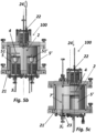
- the method of the present invention is implemented by means of an apparatus (which forms part of the present invention and which will be described in detail below) which apparatus comprises at least one deposition chamber, represented in its main aspects in Figures 4a to 5c , which deposition chamber is indicated in the drawings with the reference number 2 and is operatively connected, in a way suitable in the field, to a vacuum pump 3 (see, in particular, Figure 4c ).
- the vacuum pump 3 which is placed in fluid communication with the deposition chamber 2, optionally by means of one valve 31, optionally a throttle valve, is configured to reduce the pressure in the deposition chamber 2 within a preset operating interval ⁇ Pc.
- the deposition chamber 2 is configured to internally support at least one substrate 4 on which the growth of at least one Perovskite layer is to be obtained.
- the at least one substrate 4 is optionally made of a material selected from glass, Silicon, PEN (polyethylene naphthalate) or PET (polyethylene terephthalate), optionally but advantageously provided with a surface layer of ITO (Indium-Tin oxide) or PTAA (Polytriarylamine) or FTO (Fluoro-Tin oxide) or other metal oxides (such as TiO 2 , ZnO).
- the substrate 4 can also be made of Aluminum or Titanium or Silicon Carbide.
- At least one deposition chamber 2 which is delimited at the bottom by a bottom wall 21, there is housed at least one source 5, for example directly or indirectly inserted into a respective through opening obtained in said bottom wall 21 (as shown in Figures 5b and 5c ).
- Such a source 5 is configured to receive at least one precursor of the Perovskite which it is desired to be deposited on the at least one substrate 4, for example PbI 2 (Lead iodide) or MAI (Methylammonium iodide) or FAI (Formammidinium iodide), Csl ( Cesium iodide), SnI 2 (Tin iodide), PbCl 2 (Lead chloride), EuCl 3 (Europium chloride), EuI 2 (Europium iodide), in the form of powder, possibly also in the form of granules or tablets.
- PbI 2 Lead iodide
- MAI Metal ammonium iodide
- FAI Formammidinium iodide
- Csl Cesium iodide
- SnI 2 Tin iodide
- PbCl 2 Lead chloride
- EuCl 3 Europium chloride
- At least one delivery mouth 51 (optionally configured to be selectively open and closed) configured to allow one gas of Perovskite precursor, when generated in a way known in the field into source 5, due to the effect of heating of the source itself, pass from the source 5 into the respective deposition chamber 2.
- the at least one deposition chamber 2 is in communication with the outside through at least one inlet mouth 22 (only one represented in Figure 4c , 5b and 5c ), optionally but advantageously obtained at the top thereof, the at least one mouth 22 inlet being configured to be placed in fluid communication with at least one source 24 of one gas.
- the at least one deposition chamber 2 is also in communication with the outside through at least one outlet mouth 23 (also shown in Figure 4c , 5a-5c ), optionally but advantageously obtained at the bottom wall 21 thereof or in proximity thereto.
- the at least one inlet mouth 22 and the at least one outlet mouth 23 are configured to allow, respectively, the inlet and outlet of one gas, as will be seen better below, for example of the gas coming from source 24, in and from the at least one deposition chamber 2.
- At least one supporting device 6 (see Figures 4a and 4b ) is housed, the supporting device 6 being configured to support the at least one substrate 4 between at least one working position, wherein the at least one substrate 4 is aligned with at least one delivery mouth 51 of the at least one source 5, at a preset deposition distance d w therefrom, and one resting position, wherein the at least one substrate 4 is spaced apart from the at least one delivery mouth 51 of the at least one source 5, optionally out of alignment with respect thereto, at a distance greater than the preset deposition distance d w .
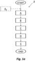
- the present invention comprises a method 1 for deposition of at least one layer of at least one Perovskite precursor on at least one substrate 4, when such at least one substrate 4 is supported in at least one deposition chamber 2 as described above, optionally in its own resting position, and when at least one precursor of such Perovskite is loaded into at least one source 5 of the at least one deposition chamber 2.
- That method 1 comprises a first operational step A wherein, for example with the at least one delivery mouth 51 closed of the at least one source 5 (which is closed before the execution of step A, if it is open), the pressure in the at least one deposition chamber 2 is reduced, by activating the vacuum pump 3 and, if present, optionally by controlling valve 31, until a working pressure value P c is reached within the interval of preset operating pressure ⁇ Pc.
- the pressure value P c within the working interval ⁇ P c can be reached in the deposition chamber 2 by activating the vacuum pump 3, until a value limit working pressure value P b is reached, which value is lower than or equal to pressure P c and therefore by controlling the valve 31, by increasing, if necessary, the pressure in deposition chamber 2 from the P b value to the P c value.
- Method 1 therefore comprises one subsequent step B wherein the precursor is sublimated in the at least one source 5, until a gas of that precursor is obtained, and one step C, wherein, if not already in the working position, the at least one substrate 4 is placed in axis with the at least one delivery mouth 51 of the at least one source 5, at the preset deposition distance d w (i.e. in its working position) and the at least one substrate is brought to a working temperature T w which will be indicated below.
- method 1 of the present invention would provide for cooling/heating such at least one substrate 4, at a working temperature depending on the type of precursor to be deposited (always lower than the temperature of the precursor source) optionally between -40°C and 300°C, by means of a suitable cooling system, during steps A and B, to control the heating of the at least one substrate 4 during the sublimation of the precursor (step B) and to prevent any contamination, due to the imperfect sealing of the at least one source 5 in the deposition chamber 2.
- step C according to this variant of method 1, therefore, the substrate 4 would then be heated or cooled to a working temperature T w which will be indicated below.
- method 1 of the present invention comprises one step D wherein the release of the gas of the precursor thus sublimated occurs, from the at least one source 5, which gas is diffused through the respective delivery mouth 51, directly (i.e. without passing through other chambers or elements of the system) towards the at least one substrate 4 and is deposited thereon at a deposition rate which varies based on the precursor, according to the pressure P c of the deposition chamber 2, the temperature of the substrate 4, and the distance d w of the substrate 4 from the respective delivery mouth 51.
- the at least one delivery mouth 51 is optionally configured to be selectively open-closed, and is closed in the previous steps of the method, at step D it opens allowing the gas to escape.
- Method 1 then comprises one step E wherein, once the precursor deposition step D is ended, the source 5 is cooled, for example by waiting for a certain time or actively, through a suitable cooling system (not shown in the Figures) and the at least one substrate 4 with the Perovskite precursor layer deposited thereon, can be moved to the resting position.
- a suitable cooling system not shown in the Figures
- the preset operational pressure interval ⁇ P c is comprised between 0.1 ⁇ 10 -3 mbar and 100x10- 3 mbar, optionally between 1x10 -2 mbar and 5x10 -2 mbar, more optionally between 2x10 -2 mbar and 4x10 -2 mbar and the preset deposition distance d w is between 0.5 cm and 5 cm, optionally between 1 cm and 3 cm, more optionally between 1.5 cm and 2.5 cm.
- both the pressure P c in the at least one deposition chamber 2 and the deposition distance d w of method 1 of the present invention are intermediate with respect to the two traditional deposition methods HV -PVD and CSS and this, as will be noted below, brings enormous benefits.
- one preliminary step (A 0 ) can be provided wherein, between the at least one inlet mouth 22 and the at least one outlet mouth 23, at least one gas it is delivered into the at least one deposition chamber 2, optionally an ultrapure gas, selected from nitrogen or a noble gas such as argon, neon or helium.
- This intermediate step advantageously allows eliminating any moisture present inside the at least one deposition chamber 2 as well as any contaminants before the activation of the vacuum pump 3 and, if provided, the valve 31 control.
- method 1 can optionally comprise introducing into the at least one deposition chamber 2, again through the aforementioned inlet mouth 22 at least one gas, optionally one or more chosen from nitrogen or another noble gas such as argon, neon, helium, also in combination with hydrogen or mixtures of these, supplied by the gas source 24 (shown in Figure 4c ), suitably connected upstream of the at least one deposition chamber 2.
- gas source 24 shown in Figure 4c
- step A includes, as already mentioned above, the activation of the vacuum pump 3 and, if present, optionally the control of valve 31, until a working pressure value P c in the at least one deposition chamber 2, comprised within the preset operational pressure interval ⁇ P c is reached, before the start of step B.
- the introduction of one gas into at least one deposition chamber 2, such as nitrogen, can be advantageous [30] to improve the characteristics of the precursor layer to be deposited on substrate 4, also by chemical reaction therewith.
- a pressure value P c within the preset pressure interval ⁇ P c , inside the at least one deposition chamber 2, can be obtained at step A:
- That adjustment of the pressure P c in the at least one deposition chamber 2 can occur by adjusting continuously or at predetermined intervals the opening-closing (or the flow rate) of the valve 31, in response to a pressure P c value inside the at least one deposition chamber 2, for example measured through a Pirani vacuum gauge (represented in Figure 4c with reference 25) or another suitable device.
- the at least one source 5 is brought to a source temperature T s between 70°C and 800°C, optionally between 80°C and 700°C, more optionally between 100°C and 600°C, which allows a good sublimation rate of the precursor contained therein and which regulates the corresponding internal pressure of source 5, without altering its state (for example, the source temperature T s must be such that is does not cause melting of the precursor).
- the source temperature T s is between 250°C and 400°C, optionally between 300°C and 370°C, more optionally between 320°C and 350°C.
- the at least one deposition chamber 2 is advantageously heated, in a way known in the field, to a temperature between 40°C and 120°C, optionally between 50°C and 100°C, more optionally between 60°C and 80°C.
- the at least one substrate 4 is brought to a working temperature T w between 30°C and 300°C, optionally between 50°C and 200°C, more optionally between 60°C and 150°C.
- the temperature at which the at least one substrate 4 is brought depends on the precursor that is to be deposited thereon. Purely by way of non-limiting example, it is of note that, if the precursor loaded in the source is PbI 2 , the working temperature T w is between 90°C and 150°C, optionally between 110°C and 140°C, more optionally between 120°C and 130°C.
- the pressure difference ⁇ P sc between the internal environment of the at least one source 5 and the at least one deposition chamber 2 is equal to or greater than 1x10 -2 mbar.
- the method 1 described above for the deposition of at least one layer of at least one PSK precursor on at least one substrate 4 is advantageously used in a method 10 of deposition of at least one layer of Perovskite on at least one substrate 4, which is the object of the present invention and is implemented in the manner described below.
- method 10 comprises the following operational steps in sequence:
- Method 10 of the present invention provides, in other words, depending on the type of PSK to be grown on the at least one substrate 4 and according to the number of precursors with which that PSK can be obtained, two or more deposition steps of its precursors, according to the methods described above, in the same deposition chamber 2 or in several deposition chambers 2 connected with each other, so that the at least one substrate 4, passing from one deposition chamber to the other, can optionally remain in a vacuum condition, for example under pressure conditions similar to those obtained in the deposition chambers 2 between which it is moved.
- method 10 of the present invention is carried out in a single deposition chamber 2 comprising a single source 5 (case not represented in the drawings), this implies that method 10, between step G and step H and/or optionally between each step H and the next one, comprises the replacement into deposition chamber 2 of the source 5 containing the at least one precursor (for example, PbI 2 ) with another source 5' containing the at least another precursor (for example for example, MAI) or the replacement, into source 5, of the at least one precursor (for example, PbI 2 ) with the at least another precursor (for example, MAI).
- the at least one precursor for example, PbI 2
- method 10 of the present invention comprises loading the respective precursor into each respective sources (5, 5 ') and moving substrate 4 between one source (for example 5 in Figures 4a to 5c ) and the other (for example 5' in Figures 4a to 5c ), between step G and step H and/or, possibly, between each step H and the following one, for example if the sources 5 were more than two.
- method 10 of the present invention is carried out in a plurality of deposition chambers 2 connected to each other in the described above suitable way, wherein each deposition chamber 2 comprises a single source 5 or more sources (5, 5 '), method 10, depending on the configuration of the system, between step G and step H and/or, possibly between each step H and the following one, may comprise:
- the present invention optionally comprises a further step F 0 , wherein the at least one deposition chamber 2 is filled with an ultrapure gas, optionally nitrogen or a noble gas such as argon, neon or helium, both to allow the venting of the at least one deposition chamber 2 and protecting the at least one substrate 4 on which the PSK layer has been deposited from contamination.
- an ultrapure gas optionally nitrogen or a noble gas such as argon, neon or helium
- respective powders of precursors (PbI 2 , MAI), in quantity between 2g and 8g, are loaded at step F in two sources 5 and 5' of a deposition chamber 2, the sources configured to be selectively open-closed.
- the average consumption for deposition of a single precursor is advantageously between 2 mg and 5 mg, depending on the size of the substrate 4, therefore it is quite clear that the sources (5, 5'), once loaded, can be used several times in the method of the present invention before it is necessary to proceed with a new refill (the average consumption of precursor can be estimated at about 2g/year).
- step F substrate 4 is placed on the supporting device 6 in its resting position.
- step G before starting the sublimation of the first precursor (corresponding to step A of method 1), the deposition chamber 2 is crossed by an ultrapure nitrogen flow (step A 0 ), to eliminate any humidity present in the deposition chamber 2 and any contaminants present therein.
- the deposition chamber 2 is filled with nitrogen and, thanks to the activation of the vacuum pump 3 and, if present optionally through control of valve 31, the pressure P c in the deposition chamber is brought within the preset interval ⁇ P c of 2-5x10 -2 mbar, which can advantageously be monitored, in a suitable way, by means of the aforementioned Pirani vacuum gauge 25 which operates in the interval between 10 mbar and 10 -3 mbar. Then, the precursor (PbI 2 ) in the first source 5 is sublimated by heating the source 5 itself, in a known way.
- the temperature of the source is equal to 350°C, in any case between 300°C and 380°C depending on the pre-established process conditions.
- the pressure difference ⁇ P sc between the interior of the source 5 and the deposition chamber 2 is approximately 1x10 -2 mbar and this makes it possible to control the properties of the precursor gas (its kinetics, energy, etc.) as desired.
- the deposition chamber 2 is heated to a temperature T w lower than 100°C (as described above) and is kept at that temperature until the end of the PSK deposition process.
- the substrate 4 is brought into the working position aligned with its delivery mouth 51, at a distance d w between 0.5cm-5cm and the delivery mouth 51 is opened. At that point the precursor gas is free to leave the source and is deposited on the substrate, in a time interval which varies according to the thickness of the precursor to be deposited on the substrate 4.
- a deposition rate of PbI 2 with the substrate at a source 5 temperature T s equal to 350°C and at a pressure in the deposition chamber 2 equal to of 4x10 -2 mbar is approximately 3 nm/min.
- the substrate is kept at a temperature of about 120°C.
- the substrate 4 is brought into the resting position, for a time interval necessary for the first source 5 to cool. That time interval can be reduced, for example, by actively cooling source 5, in a known way, by means of a suitable cooling system (not shown in the Figures).
- a second source 5' is heated to a temperature required for the sublimation of the other precursor of the AX type.
- a temperature required for the sublimation of the other precursor of the AX type such as MAI
- the temperature of the source is equal to 135°C, in any case between 100°C and 150°C depending on the pre-established process conditions.
- the substrate 4 is brought into the working position aligned with its delivery mouth 51', at a distance d w between 0.5 cm and 5cm and the delivery mouth 51 is opened.
- a deposition rate of MAI with the PbI 2 at a source 5' temperature T s equal to 135°C and at a pressure in the deposition chamber 2 equal to of 4x10 -2 mbar is approximately 2.5 nm/min.
- the substrate is kept at a temperature of about 75°C.
- step I method 10 Since in the case of MAPbI 3 deposition, in the method of the present invention the growth of the PSK layer occurs in two steps, at step I method 10 ends.
- the PSK to be deposited on the substrate was of the type A x A' 1-x B y B' 1-y (X z X' 1-z ) 3 , for example if it was a mixed Perovskite having the following formula Cs x MA 1-x Pb y Sn 1-y (I z Br 1-z ) 3
- method 10 would comprise, for example, the execution of as many deposition steps as the precursors to be deposited are, and therefore we would have:
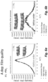
- the quality of the deposited PbI 2 layer is evaluated on the basis of the distribution curve of the growth axis of the reticular planes (rocking curve) obtained from an X-ray analysis performed on the substrate with PSK.
- the shape of that distribution curve and its width at half height show how the material deposited on the substrate according to the method of the present invention is an ordered material with a high quality of the atomic reticular order (The "lattice order" in Figure 6a is evidently higher than that of Figure 6b ), just like in an ideal material, that is, a material well-ordered at the atomic level and with a low number of lattice imperfections.
- the method described above can be advantageously implemented by means of an apparatus, indicated in the Figures with the reference number 100, for the deposition on a substrate 4 of at least one layer of at least one precursor of a PSK or of at least that PSK, which also forms the object of the present invention and includes:
- the apparatus 100 of the present invention can also comprise:
- the apparatus 100 can obtain, by means of the aforementioned control device, a pressure value P c inside the at least one deposition chamber 2, in the preset pressure interval ⁇ P c :
- the adjustment of the pressure P c inside the at least one deposition chamber 2 carried out by the control device can take place continuously or at predetermined intervals, for example in response to a value of the pressure P c inside the at least one deposition chamber 2, for example measured by a Pirani vacuum gauge 25 Pirani vacuum or other device suitable for the purpose.
- each deposition chamber 2 is inferiorly delimited by a bottom wall 21 which supports two sources (5, 5').
- the supporting device 6 housed in the respective deposition chamber 2 advantageously comprises one tray 61, rigidly fixed to a rod 62, optionally at the center thereof, which rod 62 is movably connected to a wall delimiting the deposition chamber 2 from above, optionally rotatable around its own longitudinal axis.
- tray 61 there is at least one housing seat configured for housing the substrate 4.
- the movement of rod 62 and therefore of tray 61 rigidly fixed thereto causes the displacement of the substrate 4 housed in the housing seat, between the aforementioned resting position and an aforementioned working position.
- the housing seat is delimited by a through opening that exposes an area of the substrate 4 towards the source or sources (5, 5') installed in the deposition chamber 2.
- tray 61 of the present invention several housing seats can be obtained, of variable shape and size, for example of a square shape ranging from 1.5 cm ⁇ 1.5 cm up to 15 cm ⁇ 15 cm, which therefore allow implementing the method of the present invention with substrates 4 also having each time different dimensions, slightly larger than the respective housing seats, or allow implementing the method of the present invention on several substrates at the same time, depending on the number and configuration of the sources installed into deposition chamber 2.
- the supporting device 6 in each deposition chamber 2 can be heated-cooled, by means of a suitable heating-cooling system not shown in the drawings, in order to heat-cool the at least one substrate 4 housed thereon, which must be kept within the temperature range reported above during the implementation of the method of the invention.
- the heating-cooling system of the supporting device 6 allows implementing a thermal type shielding and prevents the heating of a source in the deposition chamber 2 from affecting the temperature of the substrate 4, when not required by the method of the invention.
- the supporting device 6 is made of a material which is configured to thermally conduct well and at the same time resist corrosion. According to a preferred embodiment, given by way of non-limiting example, the supporting device 6 can be made of aluminum or copper and can be coated on the surface with an oxide layer.
- the apparatus 100 of the present invention can further comprise at least one shutter (7, 7') for each source (5, 5'), which shutter (7, 7') is configured to selectively open one or more delivery mouths (51, 51'), for each source (5, 5'), in sequence or simultaneously, according to requirements, keeping the remaining ones closed.
- shutter (7, 7') is configured to selectively open one or more delivery mouths (51, 51'), for each source (5, 5'), in sequence or simultaneously, according to requirements, keeping the remaining ones closed.
- the shutter ( 7, 7') it is possible, by controlling the shutter ( 7, 7'), obtain the opening of one or more delivery mouth (51, 51') and thus control the deposition of the precursor on a more or less wide area of one face of the substrate 4 which, in use, is aligned with the respective source (5, 5').
- the shutter (7, 7') the mechanical shielding of one source (5, 5') from the others (5', 5) is also obtained, and cross-contamination between the precursors contained in them is avoided, and in addition
- a source can be thermally shielded from the others by also actively regulating its temperature T s by means of a suitable cooling system. In this way, the sublimation of the precursor contained therein and therefore cross-contamination with the precursor or precursors of the other source or sources is prevented.
- the shutter (7, 7') of each source comprises at least one rod (71, 71') optionally extending from the bottom wall 21 delimiting the deposition chamber from below, which rod (71, 71') is configured to rotate around a pivot axis coincident with its own longitudinal axis and has a free end (710, 710') substantially at the same level of the face of the source (5, 5') wherein the delivery mouth(s) is(are) formed (51, 51').
- the shutter (7, 7') further comprises one plate-like element 72 rigidly connected to this free end (710, 710') and configured to be rotated around the pivot axis coincident with the longitudinal axis of the rod 71, whereby it can be moved between a first position, wherein it closes all the delivery outlets (51, 51') obtained in the respective source (5, 5') and respective second working positions wherein only one or more of them is left open.
- the person skilled in the art will have no difficulty in understanding how other shapes of the shutter (7, 7') of each source can be implemented and fall within the protection scope of the present invention, provided that they allow selectively opening-closing one or more delivery mouths (51, 51') of each source (5, 5').
- the apparatus 100 of the present invention can be configured to control the escape of the Perovskite precursor gas to be deposited, from the respective source (5, 5') wherein it is contained, with time intervals comparable to those of the shutter (7, 7') movement, by adjusting the pressure P c inside deposition chamber 2. In fact, if this is high with respect to the pressure P s inside the source (higher than a certain threshold value which depends on the precursor), the precursor gas will not be able to reach the substrate 4 and, therefore, to be deposited thereon.
- the method and the apparatus according to the invention overcomes the drawbacks described in the introduction.
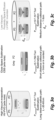
- the deposition methods and the apparatus described above allow working in "non-high" vacuum conditions, contrary to traditional systems, and arranging the substrate 4 at an intermediate distance with respect to what has been allowed up to now by the same traditional methods (see in particular Figures 3a and 3b ) with enormous advantages both in terms of cost of the equipment and in terms of waste and dispersion of the precursors used in each deposition chamber 2 and in terms of the necessary consequent cleaning and maintenance operations.
- the methods of the present invention allow regulating a greater number of process parameters (pressure of the deposition chamber 2, pressure of each source, temperature value of the substrate and distance of deposition) compared to traditional methods - as indicated in Figures 3a and 3b - and this allows precisely adjusting the thickness (which can even be half or 1/3 of the thickness obtainable with traditional methods) and the quality of the material deposited on the substrate 4.
- One further advantage is represented by the easy and rapid transfer of the precursor onto a corresponding substrate 4, and the possibility, by suitably configuring the apparatus 100 with the desired number of deposition chambers (possibly connected to each other so as to maintain the vacuum in the passage of this substrate 4 between one chamber and the other) and sources (5, 5') to sequentially apply several layers of the same precursor or of different precursors on the same substrate 4, without the need to open and close the deposition chamber 2, or on more substrates at the same time, according to the various needs.
- the method and apparatus of the present invention it is possible to deposit at least one layer of Perovskite on at least one substrate 4, by means of a method 10:
- the quality of the PSK layers obtained thanks to the present invention allows scaling down the thickness of the deposited PSK layer and the quantity of material used with the double benefit of being able to obtain semi-transparent layers of PSK which can therefore be easily used in the required fields (as mentioned in the solar cell field) and cost reduction.
- the method of the present invention and the apparatus for its implementation allow for the required scalability.
- the substrate 4 to which the method of the present invention can be applied can have dimensions ranging for example from 1.5 cm ⁇ 1.5 cm up to over 15 cm ⁇ 15 cm. This makes the method of the present invention more interesting from the point of view of its large-scale industrial application.
- the method of the present invention can be advantageously implemented to coat substrates for making Perovskite solar cells.
- the delivery mouths (51, 51') can be four in number for each source (5, 5'), obtained in a plug element which closes each source (5, 5') at the top and, if circular in shape, they can have a different diameter, depending on the geometry of the deposition chamber 2, the trajectory that the precursor gas must travel to reach the substrate 4, the trajectory followed by the substrate 4 to pass between its resting position and its working position and its size.
- the number of sources (5, 5') in each deposition chamber 2 can be adapted to the need, by composition and number of cations (A, B) and anions (X). Furthermore, it is possible to define by means of the control device of the apparatus 100 of the invention the residence time of the substrate at each source (5, 5') and it is possible to set a sequence of ad hoc deposition repetitions, to obtain the layer-by-layer deposition of different PSK precursors, so as to allow the growth of PSK layered structures of different compositions.
- the apparatus 100 in its simplest configuration, comprises at least one deposition chamber 2 and at least one vacuum pump 3 connected thereto.
- the apparatus 100 comprises, in addition to the at least one deposition chamber 2 and the at least one vacuum pump 3 connected thereto, also one source 24 of gas, connected upstream of the at least one deposition chamber 2, and in fluid communication with at least one inlet mouth 22 of the latter, and at least one valve 31, connected between the at least one deposition chamber 2 and the at least one vacuum pump 3, in fluid communication with them.
- the at least one inlet mouth 22 of the at least one deposition chamber 2 can be obtained at the bottom wall 21 of said deposition chamber, while the at least one outlet mouth 23 can be formed at the top of the at least one deposition chamber 2.
Landscapes
- Chemical & Material Sciences (AREA)
- Engineering & Computer Science (AREA)
- Materials Engineering (AREA)
- Organic Chemistry (AREA)
- Crystallography & Structural Chemistry (AREA)
- Metallurgy (AREA)
- Chemical Kinetics & Catalysis (AREA)
- General Chemical & Material Sciences (AREA)
- Inorganic Chemistry (AREA)
- Manufacturing & Machinery (AREA)
- Chemical Vapour Deposition (AREA)
- Crystals, And After-Treatments Of Crystals (AREA)
- Inorganic Compounds Of Heavy Metals (AREA)
Claims (16)
- Verfahren (1) zur Abscheidung mindestens einer Schicht mindestens eines Vorläufers von Perowskit auf mindestens einem Substrat (4) durch Verwendung mindestens einer Abscheidungskammer (2), wobei:- in der mindestens einen Abscheidungskammer (2) mindestens eine Einlassöffnung (22) und mindestens eine Auslassöffnung (23) vorhanden sind, die so konfiguriert sind, dass sie selektiv geöffnet und geschlossen werden können, um den Ein- und Austritt mindestens eines Gases in die und aus der mindestens einen Abscheidungskammer (2) zu ermöglichen;- die mindestens eine Abscheidungskammer (2) an ihrer mindestens einen Auslassöffnung (23) mit mindestens einer Vakuumpumpe (3) wirkverbunden ist;- die mindestens eine Abscheidungskammer (2) mindestens eine Quelle (5, 5') enthält, wobei die mindestens eine Quelle (5, 5') so konfiguriert ist, dass sie mindestens einen Vorläufer des Perowskits ohne Verwendung eines Trägergases aufnimmt, und die mindestens eine Quelle (5, 5') mindestens eine Zuführungsöffnung (51, 51'), die so konfiguriert ist, dass sie ein Gas des mindestens einen Vorläufers des Perowskits, wenn es in die Quelle (5, 5') sublimiert wird, direkt von der mindestens einen Quelle (5, 5') in die mindestens eine Abscheidungskammer (2) ohne Verwendung eines Trägergases passieren lässt; und- die mindestens eine Abscheidungskammer (2) mindestens eine Haltevorrichtung (6) für das mindestens eine Substrat (4) aufnimmt, wobei die Haltevorrichtung (6) so konfiguriert ist, dass sie das Substrat (4) zwischen mindestens einer Arbeitsposition, in der das mindestens eine Substrat (4) mit der mindestens einen Zuführungsöffnung (51, 5 1') der mindestens einen Quelle (5, 5') ausgerichtet ist, in einem vorgegebenen Ablagerungsabstand dW davon, und einer Ruheposition, in der es von der mindestens einen Zuführungsöffnung (51, 51') der mindestens einen Quelle (5, 5') beabstandet ist, in einem Abstand, der größer ist als der vorgegebene Ablagerungsabstand dw; und wobei- das mindestens eine Substrat (4) in der mindestens einen Abscheidungskammer (2) gehalten wird und der mindestens eine Vorläufer des Perowskits in die mindestens eine Quelle (5, 5') der mindestens einen Abscheidungskammer (2) ohne Verwendung eines Trägergases eingefüllt wird, wobei das Verfahren (1) die folgenden aufeinanderfolgenden Arbeitsschritte umfasst:A. Verringern des Drucks in der mindestens einen Abscheidungskammer (2) durch Aktivieren der Vakuumpumpe (3), bis ein Druckwert Pc, der in einem voreingestellten Betriebsdruckintervall ΔPc enthalten ist, in der mindestens einen Abscheidungskammer (2) erreicht ist;B. Sublimieren des mindestens einen Vorläufers in der mindestens einen Quelle (5, 5'), bis ein Gas des mindestens einen sublimierten Vorläufers erhalten wird;C. falls sich das mindestens eine Substrat (4) noch nicht in der Arbeitsposition befindet, das mindestens eine Substrat (4) in die Arbeitsposition bringen und das mindestens eine Substrat (4) auf eine voreingestellte Arbeitstemperatur TW bringen;D. Abscheiden des mindestens einen Gases des mindestens einen Vorläufers, der dadurch sublimiert wird, wobei das Gas die mindestens eine Quelle (5, 5') durch die mindestens eine Abgabemündung (51, 51') direkt auf das Substrat (4) verlässt, ohne ein Trägergas zu verwenden; undE. Abkühlen der mindestens einen Quelle (5, 5'); wobei das voreingestellte Betriebsdruckintervall ΔPc zwischen 0,1 x 10⁻³ mbar und 100 x 10-3 mbar, optional zwischen 1 x 10⁻² mbar und 5 x 10⁻² mbar, optional zwischen 2x10⁻² mbar und 4x10⁻² mbar, und wobei die voreingestellte Ablagerungsentfernung dW zwischen 0,5 cm und 5 cm, optional zwischen 1 cm und 3 cm, optional zwischen 1,5 cm und 2,5 cm liegt.
- Verfahren (1) gemäß Anspruch 1, wobei die mindestens eine Abgabemündung (51, 51') so konfiguriert ist, dass sie selektiv geöffnet und geschlossen werden kann, wobei Schritt A bei geschlossener mindestens einer Abgabemündung (51, 51') stattfindet und wobei Schritt D bei geöffneter mindestens einer Abgabemündung (51, 51') stattfindet.
- Verfahren (1) nach Anspruch 1 oder 2, wobei der Schritt A ferner das Zuführen des mindestens einen Gases, das gegebenenfalls ein oder mehrere Gase aus der Gruppe Stickstoff, Argon, Neon, Helium und Wasserstoff umfasst, in die mindestens eine Abscheidungskammer (2) durch die mindestens eine Einlassöffnung (22) umfasst.
- Verfahren (1) nach Anspruch 3, wobei der mindestens eine Druckwert PC innerhalb des voreingestellten Betriebsdruckintervalls ΔPC in der mindestens einen Abscheidungskammer (2) in Schritt A erhalten wird durch:- Einstellen eines Zufuhrflusses des mindestens einen Gases in die mindestens eine Abscheidungskammer(2), gegebenenfalls Halten einer Sauggeschwindigkeit der mindestens einen Vakuumpumpe (3) auf dem Maximum; oder
durch einen konstanten Zufuhrfluss des mindestens einen Gases in die mindestens eine Abscheidungskammer (2) und:∘ eine Einstellung einer Durchflussrate mindestens eines Ventils (31), optional eines Drosselventils, durch das die mindestens eine Abscheidungskammer (2) mit der mindestens einen Vakuumpumpe (3) wirkverbunden ist; und/oder∘ eine Einstellung einer Sauggeschwindigkeit der mindestens einen Vakuumpumpe (3), wobei die Einstellung der Sauggeschwindigkeit der mindestens einen Vakuumpumpe (3) optional als Reaktion auf einen gemessenen Wert des Drucks PC in der mindestens einen Abscheidungskammer (2) kontinuierlich oder in vorgegebenen Zeitintervallen durchgeführt wird. - Verfahren (1) gemäß einem der vorstehenden Ansprüche, wobei in Schritt B die mindestens eine Quelle (5, 5') auf eine Quellentemperatur T5 zwischen 70 °C und 800 °C, optional zwischen 80 °C und 700 °C, weiter optional zwischen 10 0 °C und 600 °C und/oder die mindestens eine Abscheidungskammer (2) auf eine Temperatur zwischen 40 °C und 120 °C, optional zwischen 50 °C und 100 °C, weiter optional zwischen 60 °C und 80 °C, aufgeheizt wird.
- Verfahren (1) gemäß einem der vorherigen Ansprüche, wobei in Schritt C das mindestens eine Substrat (4) auf eine Arbeitstemperatur T zwischen 30 °C und 300 °C, gegebenenfalls zwischen 50 °C und 200 °C und weiter gegebenenfalls zwischen 60 °C und 150 °C, erhitzt wird.
- Verfahren (1) gemäß einem beliebigen vorherigen Anspruch, wobei, wenn sich in Schritt A das mindestens eine Substrat (4) in der Arbeitsposition befindet, das Verfahren das Abkühlen des mindestens einen Substrats (4) während der Schritte A und B auf eine Temperatur umfasst, die niedriger ist als eine Temperatur, die in Schritt B erforderlich ist, um den mindestens einen Vorläufer in der mindestens einen Quelle (5, 5') zu sublimieren.
- Verfahren (1) gemäß einem der vorherigen Ansprüche, wobei vor dem Schritt D die Druckdifferenz ΔPsc zwischen der mindestens einen Quelle (5, 5') und der mindestens einen Abscheidungskammer (2) gleich oder größer als 1x10⁻² mbar ist.
- Verfahren (1) gemäß einem beliebigen vorherigen Anspruch, wobei das Verfahren (1) vor dem Schritt A umfasst, dass das mindestens eine Gas, gegebenenfalls ein ultrareines Gas, gegebenenfalls Stickstoff, oder ein Edelgas wie Argon, Neon oder Helium, durch die mindestens eine Abscheidungskammer (2) von deren mindestens einer Einlassöffnung (22) zu deren mindestens einer Auslassöffnung (23) strömen gelassen wird.
- Verfahren (10) zum Abscheiden mindestens einer Perowskitschicht auf mindestens einem Substrat (4), das die folgenden aufeinanderfolgenden Arbeitsschritte umfasst:F. Anordnen mindestens einer Abscheidungskammer (2), wobei:- in der mindestens einen Abscheidungskammer (2) mindestens eine Einlassöffnung (22) und mindestens eine Auslassöffnung (23) vorhanden sind, die so konfiguriert sind, dass sie selektiv geöffnet und geschlossen werden können, um den Ein- und Austritt mindestens eines Gases in die und aus der mindestens einen Abscheidungskammer (2) zu ermöglichen;- die mindestens eine Abscheidungskammer (2) an ihrer mindestens einen Auslassöffnung (23) mit einer Vakuumpumpe (3) wirkverbunden ist;- die mindestens eine Abscheidungskammer (2) mindestens eine Quelle (5, 5') beherbergt, wobei die mindestens eine Quelle (5, 5') so konfiguriert ist, dass sie mindestens einen Vorläufer des Perowskits ohne Verwendung eines Trägergases aufzunehmen, und wobei die mindestens eine Quelle (5, 5') mindestens eine Zuführungsöffnung (51, 51') aufweist, um ein Gas des mindestens einen Vorläufers des Perowskits, wenn es in der Quelle (5, 5') sublimiert wird, direkt von der mindestens einen Quelle (5, 5') in die mindestens eine Abscheidungskammer (2) ohne Verwendung eines Trägergases strömen zu lassen; und- die mindestens eine Abscheidungskammer (2) mindestens eine Haltevorrichtung (6) für das mindestens eine Substrat (4) aufnimmt, wobei die Haltevorrichtung (6) so konfiguriert ist, dass sie mindestens ein Substrat (4) zwischen mindestens einer Arbeitsposition, in der das mindestens eine Substrat (4) auf die mindestens eine Zuführungsöffnung (51, 5 1') der mindestens einen Quelle (5, 5') ausgerichtet ist, in einem vorgegebenen Abscheidungsabstand dw davon, und einer Ruheposition, in der es von der mindestens einen Abgabemündung (51, 51') der mindestens einen Quelle (5, 5') beabstandet ist, in einem Abstand, der größer ist als der vorgegebene Abscheidungsabstand dw;und wobei das Substrat (4) in der mindestens einen Abscheidungskammer (2) gehalten wird und der mindestens eine Vorläufer des Perowskits in die mindestens eine Quelle (5, 5') der mindestens einen Abscheidungskammer (2) ohne Verwendung eines Trägergases geladen wird;G. Abscheiden mindestens einer Schicht des mindestens einen Vorläufers des Perowskits auf dem mindestens einen Substrat (4) durch das Verfahren (1) gemäß einem beliebigen vorhergehenden Anspruch;H. Abscheiden mindestens einer Schicht des mindestens anderen Vorläufers des Perowskits auf dem mindestens einen Substrat (4) durch das Verfahren (1) gemäß einem beliebigen vorhergehenden Anspruch; undI. wenn auf dem Substrat (4) aufgrund einer chemischen Reaktion zwischen dem mindestens einen Vorläufer und dem mindestens anderen Vorläufer des Perowskits das Wachstum der mindestens einen Schicht des Perowskits erzielt wird, Unterbrechung des Verfahrens; andernfallsJ. Zurückgehen zu Schritt H.
- Verfahren (10) gemäß Anspruch 10, wobei:- wenn in der mindestens einen Abscheidungskammer (2) nur eine Quelle (5, 5') untergebracht ist, das Verfahren (10) zwischen dem Schritt G und dem Schritt H und/oder, falls zutreffend, zwischen jedem Schritt H und dem nächsten, den Austausch der Quelle (5 , 5') in der mindestens einen Abscheidungskammer (2), die den mindestens einen Vorläufer enthält, durch eine andere Quelle (5', 5), die den mindestens einen anderen Vorläufer enthält, oder durch den Austausch des mindestens einen Vorläufers in der Quelle (5, 5') durch den mindestens einen anderen Vorläufer; oder- wenn die mindestens eine Abscheidungskammer (2) zwei oder mehr Quellen (5, 5') umfasst, umfasst das Verfahren (10) das Laden des mindestens einen Vorläufers und des mindestens anderen Vorläufers in eine jeweilige Quelle (5, 5') und das Bewegen des Substrats (4) zwischen einer Quelle (5, 5') und der anderen, zwischen dem Schritt G und dem Schritt H und/oder, falls zutreffend, zwischen jedem Schritt H und dem nächsten; und wobeiwenn das Verfahren in zwei oder mehr Abscheidungskammern (2) ausgeführt wird, das Verfahren (10) das Bewegen des Substrats (4) zwischen einer Abscheidungskammer (2) und mindestens einer anderen Abscheidungskammer (2), zwischen dem Schritt G und dem Schritt H und/oder, falls zutreffend, zwischen jedem Schritt H und dem nächsten umfassen kann.
- Verfahren (10) nach Anspruch 10 oder 11, wobei der Druckwert (PC) der mindestens einen Abscheidungskammer (2), ein Druckwert (PS) der mindestens einen Quelle (5, 5'), der Temperaturwert des Substrats T und der Abscheidungsabstand dw innerhalb jedes Schritts G und H im Voraus oder kontinuierlich oder in voreingestellten Intervallen während der Ausführung des Verfahrens eingestellt werden.
- Verfahren (10) gemäß einem der Ansprüche 10 bis 12, wobei das Verfahren nach der Ausführung des zuletzt ausgeführten Schritts H das Zuführen von mindestens einem ultrareinen Gas in die mindestens eine Abscheidungskammer (2) umfasst, wobei das Gas optional aus der Gruppe ausgewählt wird, die Stickstoff oder ein Edelgas umfasst, das aus Argon, Neon oder Helium besteht.
- Verfahren (10) gemäß einem der vorhergehenden Ansprüche, wobei der mindestens eine Vorläufer und der mindestens eine andere Vorläufer aus der Gruppe ausgewählt sind, die Folgendes umfasst: PbI2, MAI, FAI, Csl, SnI2, PbCl2, EuCl3, EuI2, in Form von Pulver, Granulat oder Tabletten; und/oder
wobei das Substrat aus einem Material besteht, das aus der Gruppe ausgewählt ist, die Glas, Silizium, PEN, PET umfasst, und optional mit einer Oberflächenschicht aus ITO oder PTAA oder FTO oder TiO2 oder ZnO versehen ist, oder das Substrat aus Aluminium, Titan oder Siliziumkarbid besteht. - Vorrichtung (100) zur Abscheidung mindestens einer Schicht mindestens eines Perowskit-Vorläufers oder mindestens einer Perowskit-Schicht auf mindestens einem Substrat (4), umfassend:- mindestens eine Vakuumpumpe (3);- mindestens eine Abscheidungskammer (2), die mit der mindestens einen Vakuumpumpe (3) in Wirkverbindung steht, wobei in der mindestens einen Abscheidungskammer (2) mindestens eine Einlassöffnung (22) und mindestens eine Auslassöffnung (23) vorhanden sind, die jeweils so konfiguriert sind, dass sie selektiv geöffnet und geschlossen werden können, um den Ein- und Austritt mindestens eines Gases zu ermöglichen;- mindestens eine Quelle (5, 5'), die in der mindestens einen Abscheidungskammer (2) untergebracht ist, wobei die mindestens eine Quelle (5, 5') so konfiguriert ist, dass sie mindestens einen Vorläufer des Perowskits ohne Verwendung eines Trägergases aufnimmt, und wobei die mindestens eine Quelle (5, 5') mindestens eine Zuführungsöffnung (51, 51'), die so konfiguriert ist, dass sie ein Gas des mindestens einen Vorläufers des Perowskits, wenn es in der Quelle (5, 5') erhalten wird, direkt von der mindestens einen Quelle (5, 5') in die mindestens eine Abscheidungskammer (2) ohne Verwendung eines Trägergases passieren lässt;- mindestens eine Haltevorrichtung (6) für das Substrat (4), wobei die Haltevorrichtung (6) in der mindestens einen Abscheidungskammer (2) untergebracht und so konfiguriert ist, dass sie das Substrat (4) zwischen mindestens einer Arbeitsposition, in der das mindestens eine Substrat (4) mit der mindestens einen Zuführungsöffnung (51, 51') der mindestens einen Quelle (5, 5') ausgerichtet ist, in einem vorgegebenen Abscheidungsabstand dw davon, und einer Ruheposition hält, in der es von der mindestens einen Zuführungsöffnung (51, 51') der mindestens einen Quelle (5, 5') beabstandet ist, ') der mindestens einen Quelle (5, 5') ausgerichtet ist, in einem vorgegebenen Abscheidungsabstand dw davon, und einer Ruheposition, in der sie von der mindestens einen Zuführungsöffnung (51, 51') der mindestens einen Quelle (5, 5') beabstandet ist, in einem Abstand, der größer ist als der vorgegebene Abscheidungsabstand dw;- mindestens eine Steuervorrichtung, die so konfiguriert ist, dass sie das selektive Öffnen und Schließen der mindestens einen Einlassöffnung (22) und mindestens einer Auslassöffnung (23) in der mindestens einen Abscheidekammer (2) steuert, wobei die Bewegung des Substrats (4) durch die Stützvorrichtung (6) zwischen der Arbeitsposition und der der Ruheposition und zwischen der mindestens einen Quelle (5) und der mindestens anderen Quelle (5'), falls in der mindestens einen Abscheidungskammer (2) vorgesehen, oder zwischen der mindestens einen Abscheidungskammer (2) und der mindestens anderen Abscheidungskammer (2), falls in der Vorrichtung (100) vorgesehen, die Aktivierung der Vakuumpumpe (3) sowie zur Einstellung eines Druckwertes PC der mindestens einen Abscheidungskammer (2), eines Druckwertes PS der mindestens einen Quelle (5, 5'), eines Temperaturwertes des Substrats T und des Abscheidungsabstandes dw gemäß dem Verfahren gemäß einem beliebigen vorhergehenden Anspruch.
- Vorrichtung (100) nach Anspruch 15, wobei die mindestens eine Quelle (5, 5') eine Fläche umfasst, die im Gebrauch dem Substrat (4) zugewandt ist, wobei eine Vielzahl von Zuführungsöffnungen (51, 51'), optional vier, erhalten wird, wobei jede Zuführungsöffnung (51, 51') eine optional rechteckige, ovale oder kreisförmige Pflanzenkonfiguration aufweist, die sich gegebenenfalls in der Größe von den anderen Abgabemündungen der Vielzahl von Abgabemündungen (51, 51') unterscheidet, und, wenn sie kreisförmig ist, einen Durchmesser aufweist, der gegebenenfalls zwischen 0,5 cm und 1,25 cm liegt, basierend auf der Geometrie der Ablagerungskammer (2) und der Anzahl der Quellen (5, 5'), die in der mindestens einen Abscheidungskammer (2) umfasst, wobei die Vorrichtung optional mindestens einen Verschluss (7, 7') für jede Quelle (5, 5') umfasst, wobei der Verschluss (7, 7') so konfiguriert ist, dass er selektiv nur eine oder mehrere Zuführungsöffnungen (51, 51') gleichzeitig öffnet und schließt, nacheinander oder gleichzeitig, wobei die übrigen geschlossen bleiben.
Applications Claiming Priority (2)
| Application Number | Priority Date | Filing Date | Title |
|---|---|---|---|
| IT102021000001898A IT202100001898A1 (it) | 2021-01-29 | 2021-01-29 | Metodo ed apparato per la deposizione di uno strato di perovskite su un substrato |
| PCT/IB2022/050763 WO2022162607A1 (en) | 2021-01-29 | 2022-01-28 | Method and apparatus for deposition of a layer of perovskite on a substrate |
Publications (3)
| Publication Number | Publication Date |
|---|---|
| EP4284969A1 EP4284969A1 (de) | 2023-12-06 |
| EP4284969B1 true EP4284969B1 (de) | 2025-04-02 |
| EP4284969C0 EP4284969C0 (de) | 2025-04-02 |
Family
ID=75340171
Family Applications (1)
| Application Number | Title | Priority Date | Filing Date |
|---|---|---|---|
| EP22706664.4A Active EP4284969B1 (de) | 2021-01-29 | 2022-01-28 | Verfahren und vorrichtung zur abscheidung einer schicht aus perowskit auf einem substrat |
Country Status (6)
| Country | Link |
|---|---|
| US (1) | US20240117524A1 (de) |
| EP (1) | EP4284969B1 (de) |
| ES (1) | ES3025194T3 (de) |
| IT (1) | IT202100001898A1 (de) |
| PL (1) | PL4284969T3 (de) |
| WO (1) | WO2022162607A1 (de) |
Families Citing this family (1)
| Publication number | Priority date | Publication date | Assignee | Title |
|---|---|---|---|---|
| KR20240159948A (ko) * | 2022-03-11 | 2024-11-07 | 옥스퍼드 포토발테익스 리미티드 | 다성분 페로브스카이트의 제조 프로세스 |
Family Cites Families (4)
| Publication number | Priority date | Publication date | Assignee | Title |
|---|---|---|---|---|
| US6117498A (en) * | 1998-11-13 | 2000-09-12 | International Business Machines Corporation | Single source thermal ablation method for depositing organic-inorganic hybrid films |
| US20170229647A1 (en) * | 2014-05-05 | 2017-08-10 | Okinawa Institute Of Science And Technology School Corporation | System and method for fabricating perovskite film for solar cell applications |
| WO2020018626A1 (en) * | 2018-07-18 | 2020-01-23 | Massachusetts Institute Of Technology | Alternating multi-source vapor transport deposition |
| US10930494B2 (en) * | 2019-04-09 | 2021-02-23 | Swift Solar Inc. | Vapor phase transport system and method for depositing perovskite semiconductors |
-
2021
- 2021-01-29 IT IT102021000001898A patent/IT202100001898A1/it unknown
-
2022
- 2022-01-28 EP EP22706664.4A patent/EP4284969B1/de active Active
- 2022-01-28 US US18/263,254 patent/US20240117524A1/en active Pending
- 2022-01-28 PL PL22706664.4T patent/PL4284969T3/pl unknown
- 2022-01-28 WO PCT/IB2022/050763 patent/WO2022162607A1/en not_active Ceased
- 2022-01-28 ES ES22706664T patent/ES3025194T3/es active Active
Also Published As
| Publication number | Publication date |
|---|---|
| PL4284969T3 (pl) | 2025-06-23 |
| US20240117524A1 (en) | 2024-04-11 |
| ES3025194T3 (en) | 2025-06-06 |
| WO2022162607A1 (en) | 2022-08-04 |
| EP4284969A1 (de) | 2023-12-06 |
| IT202100001898A1 (it) | 2022-07-29 |
| EP4284969C0 (de) | 2025-04-02 |
Similar Documents
| Publication | Publication Date | Title |
|---|---|---|
| JP6388458B2 (ja) | 太陽電池用途向けペロブスカイト膜の製造システム及び製造方法、並びにペロブスカイト膜 | |
| US20100226629A1 (en) | Roll-to-roll processing and tools for thin film solar cell manufacturing | |
| TWI413269B (zh) | 用以將先質層轉變為光伏打吸收器之方法及設備 | |
| Qiu et al. | Rapid hybrid chemical vapor deposition for efficient and hysteresis-free perovskite solar modules with an operation lifetime exceeding 800 hours | |
| US8163090B2 (en) | Methods structures and apparatus to provide group VIA and IA materials for solar cell absorber formation | |
| US20080175993A1 (en) | Reel-to-reel reaction of a precursor film to form solar cell absorber | |
| WO2010068703A1 (en) | Reactor to form solar cell absorbers | |
| JP2017526176A (ja) | マルチソース堆積に基づくペロブスカイト膜の製造システムおよび製造方法 | |
| US20090148598A1 (en) | Methods and Apparatus to Provide Group VIA Materials to Reactors for Group IBIIIAVIA Film Formation | |
| TWI422045B (zh) | Cigs太陽能電池製程之設備及方法 | |
| CN103460405A (zh) | 一种在卷对卷过程中制备薄膜型太阳能电池吸收层的组合式反应器 | |
| US20240117524A1 (en) | Method and apparatus for deposition of a layer of perovskite on a substrate | |
| US8956698B2 (en) | Process and hardware for deposition of complex thin-film alloys over large areas | |
| US20230011303A1 (en) | Close couple diffuser for physical vapor deposition web coating | |
| TWI418047B (zh) | Ib-iiia-via2化合物半導體薄膜之製造裝置 | |
| Bobela et al. | Epitaxial crystal silicon absorber layers and solar cells grown at 1.8 microns per minute | |
| TW201034230A (en) | Reactor to form solar cell absorbers in roll-to-roll fashion | |
| CN108866515A (zh) | 一种薄膜太阳能电池吸收层的沉积掺杂装置 | |
| KR20240122643A (ko) | 기판 처리 장치 및 기판 처리 방법 | |
| WO2011135420A1 (en) | Process for the production of a compound semiconductor layer |
Legal Events
| Date | Code | Title | Description |
|---|---|---|---|
| STAA | Information on the status of an ep patent application or granted ep patent |
Free format text: STATUS: UNKNOWN |
|
| STAA | Information on the status of an ep patent application or granted ep patent |
Free format text: STATUS: THE INTERNATIONAL PUBLICATION HAS BEEN MADE |
|
| PUAI | Public reference made under article 153(3) epc to a published international application that has entered the european phase |
Free format text: ORIGINAL CODE: 0009012 |
|
| STAA | Information on the status of an ep patent application or granted ep patent |
Free format text: STATUS: REQUEST FOR EXAMINATION WAS MADE |
|
| 17P | Request for examination filed |
Effective date: 20230825 |
|
| AK | Designated contracting states |
Kind code of ref document: A1 Designated state(s): AL AT BE BG CH CY CZ DE DK EE ES FI FR GB GR HR HU IE IS IT LI LT LU LV MC MK MT NL NO PL PT RO RS SE SI SK SM TR |
|
| DAV | Request for validation of the european patent (deleted) | ||
| DAX | Request for extension of the european patent (deleted) | ||
| GRAP | Despatch of communication of intention to grant a patent |
Free format text: ORIGINAL CODE: EPIDOSNIGR1 |
|
| STAA | Information on the status of an ep patent application or granted ep patent |
Free format text: STATUS: GRANT OF PATENT IS INTENDED |
|
| RIC1 | Information provided on ipc code assigned before grant |
Ipc: H10K 85/50 20230101ALI20241002BHEP Ipc: H10K 71/16 20230101ALI20241002BHEP Ipc: C30B 35/00 20060101ALI20241002BHEP Ipc: C30B 29/12 20060101ALI20241002BHEP Ipc: C30B 23/02 20060101AFI20241002BHEP |
|
| INTG | Intention to grant announced |
Effective date: 20241030 |
|
| GRAS | Grant fee paid |
Free format text: ORIGINAL CODE: EPIDOSNIGR3 |
|
| GRAA | (expected) grant |
Free format text: ORIGINAL CODE: 0009210 |
|
| STAA | Information on the status of an ep patent application or granted ep patent |
Free format text: STATUS: THE PATENT HAS BEEN GRANTED |
|
| AK | Designated contracting states |
Kind code of ref document: B1 Designated state(s): AL AT BE BG CH CY CZ DE DK EE ES FI FR GB GR HR HU IE IS IT LI LT LU LV MC MK MT NL NO PL PT RO RS SE SI SK SM TR |
|
| REG | Reference to a national code |
Ref country code: GB Ref legal event code: FG4D |
|
| REG | Reference to a national code |
Ref country code: CH Ref legal event code: EP |
|
| REG | Reference to a national code |
Ref country code: DE Ref legal event code: R096 Ref document number: 602022012563 Country of ref document: DE |
|
| REG | Reference to a national code |
Ref country code: IE Ref legal event code: FG4D |
|
| U01 | Request for unitary effect filed |
Effective date: 20250410 |
|
| U07 | Unitary effect registered |
Designated state(s): AT BE BG DE DK EE FI FR IT LT LU LV MT NL PT RO SE SI Effective date: 20250416 |
|
| REG | Reference to a national code |
Ref country code: ES Ref legal event code: FG2A Ref document number: 3025194 Country of ref document: ES Kind code of ref document: T3 Effective date: 20250606 |
|
| PG25 | Lapsed in a contracting state [announced via postgrant information from national office to epo] |
Ref country code: NO Free format text: LAPSE BECAUSE OF FAILURE TO SUBMIT A TRANSLATION OF THE DESCRIPTION OR TO PAY THE FEE WITHIN THE PRESCRIBED TIME-LIMIT Effective date: 20250702 Ref country code: GR Free format text: LAPSE BECAUSE OF FAILURE TO SUBMIT A TRANSLATION OF THE DESCRIPTION OR TO PAY THE FEE WITHIN THE PRESCRIBED TIME-LIMIT Effective date: 20250703 |
|
| PG25 | Lapsed in a contracting state [announced via postgrant information from national office to epo] |
Ref country code: HR Free format text: LAPSE BECAUSE OF FAILURE TO SUBMIT A TRANSLATION OF THE DESCRIPTION OR TO PAY THE FEE WITHIN THE PRESCRIBED TIME-LIMIT Effective date: 20250402 |
|
| PG25 | Lapsed in a contracting state [announced via postgrant information from national office to epo] |
Ref country code: RS Free format text: LAPSE BECAUSE OF FAILURE TO SUBMIT A TRANSLATION OF THE DESCRIPTION OR TO PAY THE FEE WITHIN THE PRESCRIBED TIME-LIMIT Effective date: 20250702 |
|
| PG25 | Lapsed in a contracting state [announced via postgrant information from national office to epo] |
Ref country code: IS Free format text: LAPSE BECAUSE OF FAILURE TO SUBMIT A TRANSLATION OF THE DESCRIPTION OR TO PAY THE FEE WITHIN THE PRESCRIBED TIME-LIMIT Effective date: 20250802 |
|
| PG25 | Lapsed in a contracting state [announced via postgrant information from national office to epo] |
Ref country code: SM Free format text: LAPSE BECAUSE OF FAILURE TO SUBMIT A TRANSLATION OF THE DESCRIPTION OR TO PAY THE FEE WITHIN THE PRESCRIBED TIME-LIMIT Effective date: 20250402 |
|
| PG25 | Lapsed in a contracting state [announced via postgrant information from national office to epo] |
Ref country code: CZ Free format text: LAPSE BECAUSE OF FAILURE TO SUBMIT A TRANSLATION OF THE DESCRIPTION OR TO PAY THE FEE WITHIN THE PRESCRIBED TIME-LIMIT Effective date: 20250402 |
|
| PG25 | Lapsed in a contracting state [announced via postgrant information from national office to epo] |
Ref country code: SK Free format text: LAPSE BECAUSE OF FAILURE TO SUBMIT A TRANSLATION OF THE DESCRIPTION OR TO PAY THE FEE WITHIN THE PRESCRIBED TIME-LIMIT Effective date: 20250402 |
|
| REG | Reference to a national code |
Ref country code: CH Ref legal event code: U11 Free format text: ST27 STATUS EVENT CODE: U-0-0-U10-U11 (AS PROVIDED BY THE NATIONAL OFFICE) Effective date: 20260201 |
|
| PLBE | No opposition filed within time limit |
Free format text: ORIGINAL CODE: 0009261 |
|
| STAA | Information on the status of an ep patent application or granted ep patent |
Free format text: STATUS: NO OPPOSITION FILED WITHIN TIME LIMIT |
|
| REG | Reference to a national code |
Ref country code: CH Ref legal event code: L10 Free format text: ST27 STATUS EVENT CODE: U-0-0-L10-L00 (AS PROVIDED BY THE NATIONAL OFFICE) Effective date: 20260211 |
|
| U20 | Renewal fee for the european patent with unitary effect paid |
Year of fee payment: 5 Effective date: 20260119 |
|
| U1H | Name or address of the proprietor changed after the registration of the unitary effect |
Owner name: CONSIGLIO NAZIONALE DELLE RICERCHE; IT Owner name: KENOSISTEC S.R.L.; IT |
|
| 26N | No opposition filed |
Effective date: 20260105 |
|
| PGFP | Annual fee paid to national office [announced via postgrant information from national office to epo] |
Ref country code: GB Payment date: 20260109 Year of fee payment: 5 |
|
| PGFP | Annual fee paid to national office [announced via postgrant information from national office to epo] |
Ref country code: ES Payment date: 20260220 Year of fee payment: 5 |
|
| PGFP | Annual fee paid to national office [announced via postgrant information from national office to epo] |
Ref country code: CH Payment date: 20260201 Year of fee payment: 5 |
|
| PGFP | Annual fee paid to national office [announced via postgrant information from national office to epo] |
Ref country code: PL Payment date: 20260107 Year of fee payment: 5 |