EP4284178B1 - Vorrichtung zur herstellung von nahrungsmittelspiessen mit einem beweglichen spiessextraktor, der mit der bewegung von platten zur aufnahme von nahrungsmitteln synchronisiert ist - Google Patents
Vorrichtung zur herstellung von nahrungsmittelspiessen mit einem beweglichen spiessextraktor, der mit der bewegung von platten zur aufnahme von nahrungsmitteln synchronisiert ist Download PDFInfo
- Publication number
- EP4284178B1 EP4284178B1 EP22701965.0A EP22701965A EP4284178B1 EP 4284178 B1 EP4284178 B1 EP 4284178B1 EP 22701965 A EP22701965 A EP 22701965A EP 4284178 B1 EP4284178 B1 EP 4284178B1
- Authority
- EP
- European Patent Office
- Prior art keywords
- mobile
- spike
- extractor
- movement
- roller
- Prior art date
- Legal status (The legal status is an assumption and is not a legal conclusion. Google has not performed a legal analysis and makes no representation as to the accuracy of the status listed.)
- Active
Links
Images


Classifications
-
- A—HUMAN NECESSITIES
- A22—BUTCHERING; MEAT TREATMENT; PROCESSING POULTRY OR FISH
- A22C—PROCESSING MEAT, POULTRY, OR FISH
- A22C17/00—Other devices for processing meat or bones
- A22C17/006—Putting meat on skewers
-
- A—HUMAN NECESSITIES
- A23—FOODS OR FOODSTUFFS; TREATMENT THEREOF, NOT COVERED BY OTHER CLASSES
- A23P—SHAPING OR WORKING OF FOODSTUFFS, NOT FULLY COVERED BY A SINGLE OTHER SUBCLASS
- A23P10/00—Shaping or working of foodstuffs characterised by the products
- A23P10/10—Securing foodstuffs on a non-edible supporting member
Definitions
- the invention relates to a skewer-making apparatus comprising two movable trays positioned one on top of the other to form aligned cavities intended to receive foodstuffs.
- the invention relates more particularly to the fact that it comprises a mechanism for transferring and positioning skewers in the axis of the cavities when the latter skewer the foodstuffs.
- the invention is in the field of agri-food. Professionals have portioning devices that allow, from a product manufactured in large quantities, to produce individual portions by arranging them on skewers to facilitate cooking. More specifically, the present invention relates to a device for manufacturing skewers in which various and varied foodstuffs are aligned and skewered on a straight skewer.
- Making skewers first involves cutting compact foods such as: pieces of meat, whole or cut vegetables, fruits, sausages, cubes of cheese, etc. These different foods can be manually skewered on a skewer, one after the other.
- the skewers can be simple, thin pieces of wood that are elongated and sharpened at one end, made of bamboo for example, these skewers are generally disposable. In some cases, the non-pointed end has a flattened surface for better grip, or a sculpted head with a pattern.
- spikes exist in metal. They have the same elongated shape and have one pointed end and another forming a loop for gripping.
- a device for the manual manufacture of skewers for facilitating the skewering of foodstuffs onto skewers in order to form skewers.
- Such a device comprises a fixed base and a movable assembly slidably mounted on the fixed base.
- the movable assembly comprises lower and upper plates carrying at least one mold and at least one counter mold respectively. When the plates are positioned one on top of the other, the mold and the counter mold form longitudinal cavities capable of containing the foodstuffs previously placed on the mold.
- the fixed base further carries a retractable guide system formed by three plates each comprising notches arranged so as to hold the skewers coaxially with the axes of the cavities.
- the operator after or before having placed and positioned the foodstuffs in the dedicated cavities, the operator must take and then position one by one the skewering skewers in the notches of the guide system.
- the operation of positioning the skewers occurs in the cycle of the operations of pulling and pushing the trays and the operations of opening the trays and removing the manufactured skewers. The repetition of these actions therefore causes a certain muscular fatigue for the operator who becomes less fast and/or precise when carrying out the operation of positioning the skewers.
- the invention aims to propose a new apparatus for manufacturing skewers, comprising a mold and a counter mold making it possible to immobilize the foodstuffs during skewering and to center them in the middle of the skewers, allowing the automatic positioning of a skewer in the skewering position, thus minimizing operator intervention.
- the present invention proposes a device for manufacturing at least one skewer comprising a frame and a carriage mounted so as to slide on the frame between a front position and a rear position, and vice versa, the movable carriage comprising a lower plate cooperating with an upper plate, forming a cover, the upper plate being mounted so as to move between an open position and a closed (or folded) position, the lower and upper plates having recesses for receiving foodstuffs forming at least one row of aligned cavities when the upper plate is folded onto the lower plate and at least one orifice for the passage of a skewer opening into the axis of the at least one row of aligned cavities, the skewering of the skewer into the foodstuffs housed in the at least one row of aligned cavities being carried out by moving the movable carriage from the rear position (also called the retracted position) to the front position (also called the advanced position).
- the skewer manufacturing device comprises at least one reservoir of skewers and a mobile extractor of skewers configured to selectively remove at least one skewer from said at least one reservoir, and to extracting said at least one spike taken from the tank so as to position it opposite the at least one orifice when the mobile carriage is in the rear position, and further comprises first synchronization means configured to synchronize the movement of the mobile spike extractor with the movement of the
- the spike extractor is therefore, in the sense of the proposed technique, a mobile element which ensures the removal or release of at least one spike from the tank. To do this, the mobile spike extractor therefore engages at least partially, and temporarily, inside the tank to remove a spike, then to extract it from the tank.
- a skewer manufacturing device having such means for synchronizing the movement of the mobile skewer extractor with the movement of the mobile carriage, allows the automatic placement of the skewers in the skewering position.
- the operator advantageously keeps his or her hand(s) on the handles of the mobile carriage throughout the manufacturing process. This is advantageous compared to the prior art in which the manual removal of the skewers is time-consuming and requires particular attention on the part of the operator.
- the positioning of the spikes is also immediate in the sense that it does not cause any interruption, or a negligible interruption, in the handling of the mobile carriage. This therefore results in particular in an increase in manufacturing rates and an improvement in operator comfort and working conditions.
- the automatic positioning of the skewers in the skewering position is carried out by the skewer making device itself. This allows the device to be autonomous, i.e. not to depend on an external installation dedicated to positioning the skewers. The device is thus easily transportable and, once installed, quickly usable.
- the horizontal back and forth movement of the trays raises and lowers the blade(s) that select the pick(s) from the pick reservoir.
- the steps of pushing the trays away from the operator and pulling the trays toward the operator are synchronized with the raising and lowering of the pick selection system.
- the skewer reservoir is located below the mobile carriage, makes it possible to minimise the bulk of the skewer-making device.
- the device can be easily transported. It can also be easily stored and/or installed in relatively confined storage and/or work spaces.
- Such mechanical synchronization means make it possible to ensure precise and efficient synchronization of the movement of the mobile spike extractor with the movement of the mobile trolley.
- the absence of electronic means further allows a device comprising such synchronization means to be used in a cold and/or humid working environment, in particular by minimizing the risk of breakdowns and/or malfunctions, for example.
- Such mechanical synchronization means are also simple in design and therefore simple to maintain.
- the synchronization lever has at its first end an oblong slot cooperating with a first roller carried by the mobile spike extractor so that the pivoting of the synchronization lever causes the movement of the first roller and the movement of the mobile spike extractor between the high and low positions, and vice versa.
- Such a structure of the synchronization lever constitutes a simple and effective solution for obtaining a smooth, non-jerky and precise guidance of the mobile spike extractor between the high and low positions, and vice versa. This notably reduces the risk of unwanted ejection of the spikes from the mobile spike extractor when the latter is raised.
- the mobile spike extractor comprises a crosspiece carrying the first roller, the frame and the crosspiece carrying sliding means allowing the vertical movement of the mobile spike extractor between the high and low positions, and vice versa.
- the synchronization track comprises first and second paths extending between the first and second ends of the synchronization track, the first path being configured to be taken by the second roller when the mobile carriage moves backward, the second path being configured to be taken by the second roller when the mobile carriage moves forward.
- Such a configuration of the synchronization track makes it possible to prevent the spike carried by the mobile spike extractor from hitting the mobile carriage while allowing the mobile spike extractor to keep the spike in a stable position until it begins to enter the cavities containing the foodstuffs. This eliminates the need to implement a dedicated system for guiding and positioning the spike in accordance with previous solutions. This makes it possible in particular to simplify the construction of the device.
- the manufacturing device comprises at least one unidirectional shutter allowing the movement of the second roller inside the first path during the retraction of the mobile carriage and preventing the movement of the second roller inside the first path during the advancement of the mobile carriage to guide the second roller in the second path.
- the mobile spike extractor further comprises at least one blade for extracting a spike having on its upper face a groove for receiving and holding a spike from the tank.
- a blade which is inherently a thin element, makes it possible to prevent other spikes present in the tank from remaining in balance on a portion of the extraction blade or on the spike engaged on the blade in question.
- Such a blade also makes it possible to limit the number of spikes moved in the tank during the ascent and descent of the blades through them. This therefore results in a reduction in the risk of ejection of the spikes outside the tank.
- the extraction blade of a spike is arranged inside a slot provided in the bottom of the spike reservoir when the mobile spike extractor is in the low position, the extraction blade having a lower portion arranged inside the slot when the mobile spike extractor is in the high position.
- Such a lower portion makes it possible to prevent, in the absence of the extraction blade in the slot, the spikes present in the tank from escaping from the latter through the slots under the effect of gravity, or that unused spikes block the descent of the extraction blade.
- Such a lower portion thus makes it possible to minimize the risk of accident for the operator, by preventing him from falling after having stepped on spikes fallen to the ground for example, and to minimize the risk of malfunction, or even deterioration, of the skewer manufacturing device.
- the frame comprises at least one stop for positioning a spike against which the spike, arranged in the groove for receiving and holding the extraction blade in the high position of the mobile spike extractor, comes to bear at the start of skewering the spike into the foodstuffs housed in the row of aligned cavities.
- Such a positioning stop makes it possible, after the initiation of the skewering operation, to immobilize the base of the skewer in order to prevent it from becoming misaligned, or even breaking or being ejected. This makes it possible in particular to avoid the operator having to manually reposition or replace the skewer. It also makes it possible to minimize the risk of damage to the skewer manufacturing device, if for example a splinter of a skewer were to get stuck in the synchronization means.
- the manufacturing device comprises at least one deformable tab capable of holding the spike in the receiving groove and holding the extraction blade in the high position of the mobile extractor. pikes.
- Such a deformable tab makes it possible to ensure that the skewer is held in position in order to prevent it from being accidentally ejected at the end of the recoil phase of the mobile carriage, and therefore when the mobile skewer extractor reaches the high position.
- the skewer manufacturing device was subject to vibrations mainly when the mobile carriage and/or the mobile skewer extractor come into contact with the end-of-travel stops. Such vibrations can also appear when the mobile carriage and/or the mobile skewer extractor are subject to significant decelerations or accelerations. These decelerations or accelerations appear mainly when the mobile carriage and/or the extractor arrive in the vicinity of the end-of-travel stops, to avoid an impact against them.
- the implementation of the tabs allows to optimize the operation of the device by avoiding interrupting the manufacturing process to ensure manual repositioning of the spike and allows the operator to use the device dynamically without having to adjust or control the way of pushing or pulling the mobile carriage.
- the deformable tab is positioned on said frame below the positioning stop, and the deformable tab takes the form of a loop having an opening for the passage of a spike carried by an extraction blade of the mobile spike extractor, the deformable tab being curved towards the reservoir when the mobile spike extractor is in the low position and curved in the opposite direction when the mobile spike extractor is in the high position, a spike passing through the passage opening in the high position of the mobile spike extractor.
- Such an arrangement and such a configuration of the deformable tab allow in particular the passage of the spike through the opening dedicated to this purpose.
- the advantage of this configuration is twofold, namely allowing the spike to come to bear against the positioning stop at the start of skewering, and therefore not disrupting the operation of the device, and allowing the upper and lateral edges of the spike to be held in order to optimize the holding of the spike in the skewering position.
- the recesses of the lower and upper plates respectively support at least one mold and at least one counter mold made of a flexible material.
- the mold(s) and counter mold(s) are preferably made of silicone.
- orientation and positioning are used in this description. “lower”, “upper”, “front”, “rear”, etc. with arbitrary reference to a normal position of use of a skewer making device, in which two trays positioned one on top of the other are movable in a plane approximately parallel to the ground (horizontal) and slide between a proximal (front) and distal (rear) position relative to stops for positioning the skewers in the trays.
- the operator is located on the side of the positioning stops.
- the invention relates to a device for manufacturing one or more skewers.
- a device for manufacturing one or more skewers comprises a frame and a mobile carriage mounted so as to slide on the frame between a front position and a rear position, and vice versa.
- the mobile carriage comprises a lower plate cooperating with an upper plate, forming a cover.
- the upper plate is mounted so as to move between an open position and a closed or folded position.
- the lower and upper plates have recesses for receiving foodstuffs forming a row of aligned cavities when the upper plate is folded onto the lower plate and an orifice for passing a skewer opening into the axis of the row of aligned cavities.
- the skewers are skewered into the foodstuffs housed in the aligned cavities by moving the mobile carriage from the rear position to the front position.
- the device further comprises a reservoir of skewers, a mobile extractor of skewers configured to selectively extract one or more skewers from the reservoir.
- the extractor is configured to be introduced at least partially and temporarily into the tank in order to collect and extract one or more spikes therefrom, and to position the spike(s) opposite the corresponding passage orifice when the mobile carriage is in the rear position.
- the device also comprises synchronization means configured to synchronize the movement of the mobile spike extractor with the movement of the mobile carriage.
- the forward and backward movement of the mobile carriage allows the skewers to be extracted from the tank by means of the mobile extractor and to be placed in position for skewering, while the backward and forward movement of this same mobile carriage allows the skewering of the foodstuffs arranged between the trays onto the skewers.
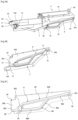
- FIGS. 1A to 1C present in perspective, according to different views, an example of a skewer manufacturing device in which the movement of a mobile skewer extractor, configured to pick up and extract skewers from a reservoir of the device and place the extracted skewers in a position for skewering foodstuffs, is synchronized with the movement of a mobile carriage carrying pivoting trays, in accordance with the proposed technique.
- the skewer manufacturing device 1 comprises a frame 2 equipped with feet intended to place the device 1 on a surface, preferably horizontal.
- the frame 2 further comprises a rectangular empty space (not referenced) intended to receive other elements of the device as we will see in more detail later.
- the device 1 further comprises a mobile carriage 3 comprising a first tray 31, called the lower tray, and a second tray 32, called the upper tray.
- the lower tray 31 is arranged in the rectangular empty space of the frame 2.
- the upper tray 32 forming a cover, is pivotally mounted on the mobile carriage 3, by means of a hinge 33, between a closed position P F or folded down, shown in [ Fig. 1A ], and an open position PO, represented in Figures 1B notably.
- the lower and upper trays 31, 32 respectively have recesses 310, 320 for receiving foodstuffs forming, when the upper tray 32 is folded down onto the lower tray 31, parallel rows of aligned cavities.
- the axis X further defines the longitudinal axis of the device 1.
- the lower and upper trays 31, 32 respectively have on one of their edges complementary notches forming, when the upper tray 32 is folded down onto the lower tray 31, orifices 34 for the passage of a spike.
- Each orifice 34 is oriented along the longitudinal axis X of a cavity and opens into the interior thereof, as illustrated in relation to the [ Fig.1C ] notably.
- the mobile carriage 3 is slidably mounted on the frame 2 along the longitudinal axis X between a front position P AV and a rear position P AR , and vice versa.
- the mobile carriage 3 In the forward position P AV , as illustrated in relation to the [ Fig.1A ] in particular, the mobile carriage 3 is substantially pressed against positioning stops 4 of the spikes, on the user side.
- These positioning stops 4 of the spikes which are more visible in [ Fig.8A ] in particular, are carried by a front portion 21 of the frame 2 on the side from which the user positions himself to operate the device.
- the positioning stops 4 are configured to immobilize the base of the spikes, that is to say the end of the spike opposite the tip, so as to prevent the unwanted movement of the spikes along the longitudinal axis X during the operation of skewering the foodstuffs onto the spikes.
- the mobile carriage 3 In the rear position P AR , as illustrated in relation to the [ Fig.1C ] in particular, the mobile carriage 3 is moved away from the positioning stops 4 by a distance greater than the length of the spikes P so as to allow the positioning of a spike extracted from the reservoir opposite each of the orifices 34 of the mobile carriage 3.
- the skewering of the food housed in the cavities on the spikes is therefore carried out by moving the mobile carriage 3 from the rear position P AR to the front position P AV .
- the skewer-making device 1 further comprises two handles 5 placed at the front of the upper plate 32, that is to say opposite the hinge 33.
- the handles 5 make it possible to actuate the pivoting of the upper plate 32 as well as the sliding of the mobile carriage 3 relative to the frame 2.
- the device may comprise a single handle provided that it makes it possible to carry out the aforementioned operations.
- the device 1 comprises a reservoir 10 of unused spikes which extends along the longitudinal axis X of the device 1.
- the reservoir 10 is arranged inside the rectangular empty space of the frame 2, below the lower plate 31 of the mobile carriage 3, and is fixed in an irremovable manner to the frame 2.
- the device 1 further comprises a mobile spike extractor, configured to selectively pick up and extract spikes from the reservoir 10 in a first step, then to position a spike extracted from the reservoir opposite each of the orifices 34 when the mobile carriage 3 is in the rear position P AR .
- the device 1 further comprises synchronization means configured to synchronize the movement of the mobile spike extractor with the movement of the mobile carriage 3.
- the mobile spike extractor and the synchronization means not visible on the Figures 1A, 1B And 1C , will be described in detail later.
- the device 1 comprises two aligned cavities for receiving food products, which are formed by the recesses 310, 320, and is thus capable of manufacturing two skewers at the same time.
- the device according to the invention can also be adapted to the manufacture of a single skewer or three or nine, or any number, depending in particular on the number of aligned cavities for receiving food products provided in the mobile carriage 3.
- the recesses 310, 320 of the lower and upper trays 31, 32 respectively support a removable mold 311 and counter mold 321 made of a flexible material, such as silicone or a thermoplastic elastomer, so as not to damage the foodstuffs during the skewering operation.
- the hardness of the soft material is determined to ensure correct support while preserving the integrity of the foodstuffs.
- the hinge 33 for rotating the upper plate 32 is arranged at the rear of the mobile carriage 3 so as to simplify the handling of the device 1.
- the carriage 3 is mounted so as to slide on the frame 2 by means of two slides 22 carried by the frame 2.
- the slides 22 are formed by two rods, extending along the longitudinal axis X of the device 1, arranged inside the rectangular empty space of the frame 2 below the lower plate 31 of the mobile carriage 3.
- the longitudinal ends of each rod 22 are secured on either side of the frame 2, namely to the front portion 21, forming a front sliding stop, and to a rear portion (not visible), forming a rear sliding stop.
- the device 1 comprises deformable tabs 12 capable of holding the spike on the mobile spike extractor.
- deformable tabs 12 capable of holding the spike on the mobile spike extractor.
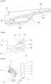
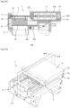
- FIG.2 shows in perspective, and in isolation, an example of a mobile skewer extractor mounted in a sliding manner on the frame of the skewer manufacturing device.
- the mobile spike extractor 6 is, according to the example illustrated, mounted so as to slide on the frame 2 between a low position and a high position, and vice versa so that the extraction and positioning of the spikes (not shown) opposite the orifices of the mobile carriage are carried out by moving the mobile spike extractor 6 from the low position to the high position.
- Extraction blades 61 carried by the mobile spike extractor 6, ensure the collection and extraction of the spikes stored in the tank and then the positioning of these spikes opposite the orifices of the mobile carriage.
- the mobile spike extractor 6 has as many extraction blades 61 as there are rows of cavities present in the mobile carriage.
- the extraction blades respectively have a shorter length than the length of the spikes to avoid any contact with the mobile carriage during operation of the device. These blades are arranged so as to be able to pass through the spike reservoir.
- the mobile spike extractor 6 carries a first roller 62 forming part of the means for synchronizing the movements of the mobile spike extractor 6 and the mobile carriage 3 which will be detailed later.
- the mobile spike extractor 6 comprises a main body, substantially of rectangular parallelepiped shape, also called crosspiece 60, mounted so as to slide on the frame 2.
- the mobile spike extractor 6 has two through holes 63 configured to cooperate with two vertical slides 23 carried by the front portion 21 of the frame 2.
- the slides are formed by two vertical rods 23 whose longitudinal ends are secured on either side of the front portion 21 of the frame 2, namely to an upper part 211, forming an upper sliding stop, and to a lower part 212, forming a lower sliding stop.
- the mobile spike extractor 6 comprises two parallel extraction blades 61 projecting perpendicularly from the crosspiece 60 and being oriented along the longitudinal axis X of the device 1 in the direction of the mobile carriage 3.
- each extraction blade 61 is oriented vertically and has a thickness corresponding substantially to the diameter of the spikes so as to ensure that each extraction blade 61 grasps only one spike at a time within the tank and then extracts it from the tank. Indeed, such a thickness makes it possible to prevent other spikes of the tank from remaining balanced on a portion of the extraction blade or on the spike engaged on the blade. Such an arrangement also makes it possible to limit the number of spikes moved in the compartments of the tank during the ascent and descent of the blades therethrough. This therefore results in a reduction in the risk of ejection of the spikes outside the tank.
- the extraction blades 61 each have, on their upper face 610, a groove 611 intended to receive and hold a spike present in the reservoir 10. Such a groove 611 makes it possible to minimize the risk of the extracted spike falling back into the reservoir 10 when the device 1 is being handled by the operator.
- the first roller 62 is secured to a support element projecting perpendicularly from the crosspiece 60 and being oriented along the longitudinal axis of the device 1.
- the first roller 62 is arranged substantially in the middle of the crosspiece 60.
- a groove 66 is further provided in the crosspiece 60, opposite the first roller 62, so as to allow the passage of the synchronization means, namely the first end of the synchronization lever as illustrated in relation to the Figures 10B And 13B notably.
- each extraction blade 61 carries a lower portion 64, formed by a plate, configured to prevent the spikes present in the reservoir from accidentally entering inside a slot 102 for receiving the extraction blade 61, as illustrated in relation to the Figures 7A And 7B notably.
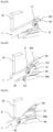
- FIGS. 3A to 3D are different views of an example of means for synchronizing the movement of the mobile skewer extractor with the movement of the mobile carriage in a skewer manufacturing device according to the invention.
- the synchronization means are configured to link the vertical sliding of the mobile spike extractor to the horizontal sliding of the mobile carriage.
- the synchronization means are configured to synchronize the raising of the mobile spike extractor 6 from the low position to the high position with the movement of the mobile carriage 3 from the front position to the rear position, corresponding to a backward movement of the mobile carriage 3, and the lowering of the mobile spike extractor 6 from the high position to the low position with the movement of the mobile carriage 3 from the rear position to the front position, corresponding to an advancement of the mobile carriage 3.
- synchronization means comprising a synchronization lever 7, a second roller 8 carried by the synchronization lever 7, a synchronization track 9 arranged on the mobile carriage 3 in which the second roller 8 is mobile in sliding and a first roller 62 of the mobile spike extractor 6 cooperating with the synchronization lever 7.
- the synchronization lever 7 has a substantially “L” shape and is pivotally mounted, at its elbow, on the frame (not shown).
- the synchronization lever 7 has a first longitudinal end 71, called the first end, and a second longitudinal end 72, called the second end, located opposite the first end 71.
- the first end 71 has an oblong slot 710 configured to receive the first roller 62 carried by the mobile spike extractor 6.
- the first roller 62 is configured to be movable inside the oblong slot 710 during operation of the device. More specifically, and as described and illustrated in more detail below, detail later, the oblong light 710 allows the vertical movement of the first roller 62 during the pivoting of the synchronization lever 7.
- the second end 72 of the synchronization lever 7 carries the second roller 8, partially visible in [ Fig.3B ], configured to move inside the synchronization track 9 provided on the mobile carriage 3.
- the synchronization track 9 is provided on a lateral face 350 of a plate 35 fixed under the lower plate 31.
- the plate 35 is oriented along the longitudinal axis of the device 1 so as to have a first longitudinal end 351 located at the rear of the mobile carriage 3 and a second longitudinal end 352 located at the front of the mobile carriage 3.
- the synchronization track 9 has a first end 91 associated with the low position of the mobile spike extractor 6, and a second end 92 associated with the high position of the mobile spike extractor 6.
- the first end 91 of the synchronization track 9 is located at the first longitudinal end 351 of the plate 35 in the vicinity of the lower plate 31. In other words, the first end 91 of the synchronization track 9 is located in the upper rear part of the plate 35.
- the second end 92 of the synchronization track 9 is located at the second longitudinal end 352 of the plate 35, at a distance from the lower plate 31.
- the second end 92 of the synchronization track 9, which is diagonally opposite the first end 91, is located in the lower part of the second longitudinal end 352 of the plate 35.
- the synchronization track 9 further has a first path 93, configured to be taken by the second roller 8 when the mobile carriage 3 moves back, and a second path 94, configured to be taken by this same second roller 8 when the mobile carriage 3 moves forward. These paths both extend between the first and second ends 91, 92.
- the first path 93 comprises a first segment 930 starting from the first end 91 and extended by a second segment 931 opening into the second end 92.
- the second roller 8 when it circulates in this first path thus describes a downward trajectory.
- the first segment 930 is configured to initiate a slow rise of the mobile spike extractor as long as the mobile carriage is positioned above the extraction blades and the spikes carried by them.
- the second segment 931 is configured to allow the rapid rise of the mobile spike extractor as long as the mobile carriage is sufficiently far from the extraction blades and the spikes carried by them.
- the first segment 930 has, relative to the longitudinal axis of the device, that is, relative to a horizontal axis, a first slope of angle ⁇ and the second segment 931 has a second slope of angle ⁇ .
- the value of the angle ⁇ is greater than the value of the angle ⁇ .
- the second path 94 comprises a first segment 940 starting from the second end 92 and extended by a second segment 941, itself extended by a third segment 942 opening into the first end 91.
- the second roller 8 thus describes an upward trajectory when it travels in this second path.
- the first segment 940 is configured to hold the mobile spike extractor in the high position until the spikes carried by the extraction blades enter the passage holes opening into the cavities of the mobile carriage.
- the second segment 941 is configured to initiate a rapid descent of the mobile spike extractor to prevent the mobile carriage from hitting the extraction blades when it approaches the operator.
- the third segment 942 is configured to continue the slow descent of the mobile spike extractor to the low position so as to prepare the extraction of the spikes for the next operating cycle of the device.
- the first segment 940 has, relative to the longitudinal axis of the device, a slope of zero angle
- the second segment 941 has a slope of angle y
- the third segment 942 has a slope of angle ⁇ .
- the first segment 940 of the second path 94 has a length less than the first segment 930 of the first path 93 and the value of the angle y of the second segment 941 of the second path 94 is substantially greater than the value of the angle ⁇ of the second segment 931 of the first path 93.
- the angle ⁇ is determined so as to ensure a rapid descent of the extraction blades 61 to compensate for their immobility during the sliding of the roller 8 in the first segment 940 of the second path 94. In other words, the angle ⁇ is determined to prevent the extraction blades 61 from striking the mobile carriage 3.
- Such constraints mean that the second segment 941 of the second path 94 opens into the first segment 930 of the first path 93 and therefore that the third segment 942 of the second path 94 is merged with a portion of the first segment 930 of the first path 93.
- Figures 4A and 4B present, in different perspective views, and in a focused manner, the structure of a one-way shutter.
- Figures 5A to 5D illustrate the movement of the one-way shutter as the second roller moves in the timing track.
- the one-way shutter 11 also called a flap, is configured, on the one hand, to allow the movement of the second roller 8 inside the first path 93 of the synchronization track during the retraction of the mobile carriage 3 and to guide the second roller 8 towards the second end of the synchronization track 9.
- the one-way shutter 11 is configured, on the other hand, to prevent the movement of the second roller 8 inside this same first path 93 during the advancement of the mobile carriage 3 and to guide the second roller 8 towards the second path 94.
- the one-way shutter 11 is located between and at the intersection of the second segment 931 of the first path 93 and the first segment 940 of the second path 94. It is arranged so as to separate the two paths 93, 94.
- the one-way shutter 11 has, at a first end 110, a rotation shaft (not visible) arranged in an orifice (not visible) of the plate 35 and secured to the latter by means of a screw 13 to allow the pivoting of the one-way shutter 1, as illustrated in relation to the [ Fig.4B ].
- a spring 14 is secured, on the one hand, to the one-way shutter 11 and, on the other hand, to the plate 35.
- the spring 14 is configured to return and maintain the one-way shutter 11 through the first path 93 in the absence of pressure exerted by the second roller 8 on the shutter 11.
- the turns 140 of the spring 14 are carried by the rotation shaft of the one-way shutter 11 and the two straight ends 141, 142 of the spring 13, also called strands, are coupled to the plate 35 and to the one-way shutter 11. More precisely, the one-way shutter 11 has a lug 112 projecting parallel to the rotation shaft, arranged in an orifice 353 of the plate 35 to retain the end 142 of the spring 14.
- the one-way shutter 11 further has a second end 111, opposite the first end 110, an upper face 113, arranged opposite the first path 93, and a lower face (not visible), arranged opposite the second path 94.
- the second roller 8 When moving the second roller 8 in the second segment 931 of the first path 93, as illustrated in relation to the Figures 5A and SB, the second roller 8 gradually puts pressure on the upper face 113 of the one-way shutter 11, causing the latter to pivot and compress the spring 14, until the second end 111 of the one-way shutter 11 is pressed against the wall of the first segment 940 of the second path 94.
- the upper face 113 locally extends an edge of the second segment 931 of the first path 93, thus guiding the second roller 8 towards the second end 92 of the synchronization track 9.
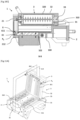
- FIG.6 presents in perspective, and in isolation, an example of a tank storing a batch of unused P spikes.
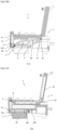
- the Figures 7A And 7B are cross sections of an extraction blade, in low position P B and high P H respectively, cooperating with the reservoir.
- each compartment 100 comprises an inclined bottom 101 ending in its lowest part with a slot 102, of rectangular parallelepiped shape, arranged vertically. Such an inclination makes it possible to orient the spikes towards the extraction blades when they are arranged in the slots.
- Each slot 102 is configured to receive, on the one hand, an extraction blade 61 which, when it rises within the reservoir, ensures the collection and extraction of a spike from the reservoir and, on the other hand, a lower portion 64 intended to prevent the spikes from entering the slot 102 in the absence of the extraction blade 61.
- each extraction blade 61 is preferably entirely housed in the associated slot 102 so as to ensure the positioning of a spike P in the dedicated receiving groove 611.
- Fig.7B represents the extraction blade 61 in the high position P H .
- the extraction blade 61 ensures the positioning of the spike P positioned in the groove 611 for the skewering operation.
- the lower portion 64 remains partially arranged inside the slot.
- the lower portion 64 of the blade remains partially disposed inside the slot 102 throughout the movement of the extraction blade 61 from the low position P B to the high position P H , and vice versa.
- Such an arrangement prevents unused spikes present in the tank from escaping from it through the slots, under the effect of gravity, or unused spikes from blocking the descent of the extraction blade.
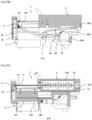
- FIGS 8A to 8C show, in different views, an example of deformable tabs shown in different positions.
- the deformable tabs 12 are capable of holding the spike opposite the orifices when the mobile carriage reaches the rear position, and therefore when the mobile spike extractor 6 reaches the high position P H , in order to prevent sudden use of the device 1 from ejecting the spikes from the grooves 611 of the extraction blades 61.
- the deformable tabs 12 are positioned on the frame 2 below the positioning stops 4 and are curved towards the tank 10 when they are not stressed (at rest). This occurs as soon as the extraction blades 61 begin to be lowered sufficiently to no longer come into contact with them, as illustrated in relation to the Figures 8A and 8B .
- Each deformable tab has a passage opening 120 configured to allow the passage of a portion of the associated extraction blade 61 and the spike P carried by the latter.
- the spike carried by each extraction blade 61 comes into contact with a portion of the corresponding deformable tab 12, causing it to gradually deform until it is curved in the opposite direction, allowing the spike to pass through the passage opening 120.
- the deformable tab 12 which tends to return to its undeformed position downwards, presses the spike into the groove of the extraction blade 61.
- the deformable tabs 12 here take the form of loops made of elastomer.
- the deformable tabs are fixed by means of screws 13 on an inclined wall 210 of the front part 21 of the frame 2, located under each positioning stop 4. Such an arrangement encourages the deformable tabs 12 to be curved towards the reservoir 10 when they are not stressed by the mobile spike extractor 6.
- the organization chart of the [ Fig.9 ] focuses on the main operating steps of the food skewer manufacturing device.
- the Figures 10A to 15C are views of the skewer making device illustrating the main operating steps, for a better understanding of the proposed technique.
- the mobile carriage 3 In the initial position, illustrated in relation to the Figures 10A to 10C , the mobile carriage 3 is pressed against the front portion 21 of the frame 2 so as to be in the front position P AV , close to the user.
- the second roller (not visible) carried by the second end 72 of the synchronization lever 7 is positioned in the first end 91 of the synchronization track 9.
- the upper plate 32 is folded down onto the plate 31.
- the mobile spike extractor 6 is pressed against the lower part 212 of the front portion 21 of the frame 2 so as to be in the low position P B.
- the first roller 62 of the mobile spike extractor 6 is located near the rear end of the oblong slot 710 formed on the first end 71 of the synchronization lever 7.
- the extraction blades 61 of the mobile spike extractor 6 are housed in the slots 102 of the compartments 100 of the reservoir so that a spike is inserted into the groove 611 of each extraction blade 61.
- a first step referenced S1 and illustrated in relation to the Figures 11A to 11C , the operator places the foodstuffs in the recesses of the lower tray 31 of the mobile trolley. If an operating cycle of the skewer making device has previously been implemented, the operator obviously removes the made skewers from the lower tray 31 before inserting foodstuffs into the recesses of the lower tray 31.
- the operator manipulates the handles 5 of the device 1 to bring the upper tray 32 into the open position P O , places the foodstuffs (shown in broken lines) on the molds 311 of the lower tray 31 so as to center them relative to the orifices 34 then folds the upper tray 32 against the lower tray 31 to return to the closed position P F .
- the foodstuffs placed in the cavities of the mobile carriage 3 are thus held without being crushed by the molds 311 and counter molds 321 of the lower 31 and upper 32 trays respectively.
- the recoil of the mobile carriage 3 along the slides 22 forces the second roller 8 to leave the first end 91 of the synchronization track 9 to take the first segment 930 of the first path 93.
- the slope of the first segment 930 being slight, the movement of the second roller 8 causes a slow pivoting of the synchronization lever 7.
- the first end 71 of the synchronization lever 7 therefore moves the first roller 62 to slowly slide the crosspiece 60 along the slides 23.
- the mobile spike extractor 6 leaves the low position allowing the extraction blades 61 to dislodge from the slots 102 of the compartments 100 of the reservoir in order to extract spikes P.
- the slow rise of the mobile spike extractor prevents the extraction blades 61 and the extracted spikes from hitting the mobile carriage 3 located above them.
- deformable tabs 12 which are not stressed, are curved towards the spike reservoir.
- the second roller 8 takes the second segment 931 of the first path 93 until reaching the second end 92 of the synchronization track 9 having previously passed the one-way shutter 11, as described in relation to the Figures 5A to 5D .
- the slope of the second segment 931 being greater than that of the first segment 930, the movement of the second roller 8 causes a rapid pivoting of the synchronization lever 7 and therefore a rapid rise of the mobile spike extractor 6 and its extraction blades 61.
- the rapid rise of the extraction blades 61 each carrying a spike P makes it possible to compensate for the slow rise of the first phase.
- the first roller 62 of the mobile spike extractor 6 is located near the front end of the oblong slot 710 provided on the first end 71 of the synchronization lever 7.
- the lower portions 64 of the extraction blades 61 are partially arranged in the slots 102 of the compartments 100 of the tank to prevent the spikes from entering the slots 102.
- the deformation of the deformable tabs 12 is such that they hold the base of the spikes to prevent the shocks occurring when the carriage reaches the rear stop from dislodging the spikes from the grooves of the extraction blades 61.
- a third skewering step referenced S3 and illustrated in relation to the Figures 14A to 15C , the operator manipulates the handles 5 to pull or move forward, that is to say towards him, the mobile trolley 3 in order to skewer the foodstuffs onto the spikes, that is to say the insertion of the spikes into the foodstuffs located between the trays in the mobile trolley.
- the advancement of the movable carriage 3 forces the second roller 8 to leave the second end 92 of the synchronization track 9 to take the first segment 940 of the second path 94.
- the one-way shutter 11 prevents the second roller 8 from taking the first path 93, as described in relation to the Figures 5A to 5D .
- the slope of the first segment 940 of the second path 94 being zero, the movement of the second roller 8 in this portion does not cause any pivoting of the synchronization lever 7.
- the mobile spike extractor 6 therefore remains in the high position P H so that the extraction blades 61 hold the spikes P at the start of the skewering operation, as described below.
- the spikes are introduced into the orifices 34 of the mobile carriage.
- the spikes come into contact with the first foodstuffs, initially, the spikes move back slightly and the bases of the spikes come to position themselves in the positioning stops 4. It is only after such a support that the spikes begin to skewer themselves into the foodstuffs.
- the second roller 8 takes the second segment 941 of the second path 94.
- the slope of the second segment 941 of the second path 94 being significant, as described in relation to the [ Fig.4A ] in particular, the movement of the second roller causes the synchronization lever 7 to pivot rapidly.
- the first end 71 of the synchronization lever 7 therefore moves the first roller 62 to cause the crosspiece 60 to slide rapidly along the slides 23.
- the mobile spike extractor 6 thus leaves the high position in order to allow the extraction blades 61 to disengage rapidly while leaving the spikes P in position of skewering.
- a rapid descent of the extraction blades 61 is necessary to compensate for their immobility during the first descent phase in order to prevent them from hitting the mobile carriage 3.
- the spikes continue to be inserted into the cavities containing the foodstuffs. Furthermore, the lower portions 64 of the extraction blades 61 are inserted into the slots 102 of the compartments 100 of the tank.
- the second roller 8 takes the third segment 942 of the second path 94 until reaching the first end 91 of the synchronization track 9 to return the device 1 to the advanced position. Since the third segment 942 of the second path 94 corresponds to a portion of the first segment 930 of the first path 93 and therefore has the same slope, as described in relation to the [ Fig.3D ] in particular, the movement of the second roller causes a slow pivoting of the synchronization lever 7 and therefore a slow descent of the mobile spike extractor 6 and its extraction blades 61.
- the mobile carriage 3 gradually bends the deformable tabs 12 upwards (away from the tank) until they are pressed against the front part 21 of the frame 2.
- the deformable tabs 12 do not in any way disrupt the skewering operation.
- the device 1 is then in the initial position, as illustrated in relation to the Figures 10A to 10C , and the skewers are housed in the mobile cart through the food, the skewers obtained can then be recovered by the user.
- the skewers are placed while the mobile trolley with the cavities containing the food is moving. This automatic placement of the skewers does not extend the duration of the skewer manufacturing process but, on the contrary, reduces it. This results in particular in an increase in manufacturing rates and an improvement in the comfort and working conditions of the operator.
- the operator can keep his hands on the handling handle(s) during the entire skewer manufacturing process. Again, this allows for improved operator comfort.
- the holes provided in the crosspiece of the mobile spike extractor which are configured to cooperate with the vertical rods of the frame, carry ball bushings to ensure precise guidance of the mobile spike extractor relative to the frame.
- the lower portions of the extraction blades are made of a plastic material in order to limit the weight and production costs of the skewer manufacturing device.
- the means for synchronizing the movement of the mobile spike extractor with the movement of the mobile carriage implement electronic and/or electromechanical means.
- the synchronization means comprise, according to a particular embodiment, first sensors configured to determine the horizontal position of the mobile carriage and the speed of movement thereof, second sensors configured to determine the vertical position of the extraction blades and the speed of movement thereof, at least one actuator, linear or rotary, configured to vertically move the extraction blades and a processing unit, such as an automaton, configured to control, in position and speed, the movement of the extraction blades relative to the position and speed of movement of the mobile carriage carrying the trays.
- the device further comprises an interface allowing an operator to adjust all or part of the operating parameters of the device, and in particular the electronic synchronization means.
- the device may comprise electronically adjustable stops so as to block the sliding of the mobile carriage at a predetermined position depending on the length of the spikes entered on the interface.
- the sliding amplitude of the mobile carriage will be reduced for short spikes for example. This makes it possible in particular to improve the comfort and work rate of the operator and to minimize unnecessary actions.
- the spike reservoir comprises a single compartment having a convex bottom and the lower parts of which end in vertical slots.
- each extraction blade is substantially comb-shaped to further reduce the weight of the skewer-making device.
- each extraction blade and its lower portion are made from a single, single-piece part.
- each deformable tab has one end fixed above a positioning stop and a free end on which the passage opening is provided.
- the deformable tabs are carried by the mobile carriage either by the upper plate or by the lower plate.
- the choice of the positioning of the deformable tabs depends essentially on their shape and/or the positioning of the passage openings, if present, of the extraction blades.
- the skilled person will be able to adapt the shape and arrangement of the mobile skewer extractor, as well as the elements that compose it, according to the overall structure of the skewer manufacturing device, and in particular the number of skewers that it must manufacture.
- the skewer manufacturing device is configured to allow the simultaneous manufacture of four skewers
- the device may comprise two mobile skewer supports conforming to that illustrated or only one mobile skewer extractor carrying four extraction blades and a first roller, or even several for a better distribution of the forces.
- the skilled person will also be able to determine the length and/or the slope of each segment forming the synchronization track so as to obtain the operation described according to the dimensions and structural variants of the device in particular.
- the arrangement of the synchronizing lever and the synchronizing track is reversed, by providing the synchronizing track in/on the movable extractor and pivotally attaching the synchronizing lever to the movable carriage.
- the skewer making device comprises a fixed support carrying the lower and upper plates and a movable frame/chassis. Thus, the operator no longer slides the plates but the movable chassis carrying the movable skewer extractor.
- the proposed technique covers all implementations of the principle according to which the movement of an extraction member of at least one spike present in a reservoir and the positioning of said at least one spike opposite of at least one cavity of the trays containing the foodstuffs, is synchronized with the movement of the mobile trolley carrying the trays.
- the solution of the proposed technique therefore makes it possible to have a skewer manufacturing device allowing automatic and immediate positioning of the skewers, without manual intervention, in the sense that it does not cause any interruption, or a negligible interruption, in the handling of the mobile trolley.
- the device allows the production of skewers of foods such as meat and/or vegetables, fish, fruits or others.
- the spikes can be made of wood, plastic or metal.
- the upper plate can move parallel to the lower plate and not pivotally relative to the latter.
Landscapes
- Life Sciences & Earth Sciences (AREA)
- Engineering & Computer Science (AREA)
- Food Science & Technology (AREA)
- Chemical & Material Sciences (AREA)
- Polymers & Plastics (AREA)
- Wood Science & Technology (AREA)
- Zoology (AREA)
- Formation And Processing Of Food Products (AREA)
- Meat, Egg Or Seafood Products (AREA)
- Baking, Grill, Roasting (AREA)
Claims (12)
- Vorrichtung (1) zum Herstellen mindestens eines Spießes mit einem Gestell (2) und einem beweglichen Wagen (3), der gleitend auf dem Gestell (2) zwischen einer vorderen Position (PAV) und einer hinteren Position (PAR), und umgekehrt, beweglich montiert ist, wobei der bewegliche Wagen (3) eine untere Platte (31) aufweist, die mit einer oberen Platte (32) zusammenwirkt und einen Deckel bildet, wobei die obere Platte (32) zwischen einer offenen Position (Po) und einer geschlossenen oder umgeklappten Position (PF) beweglich montiert ist, wobei die untere und obere Platte (31, 32) Vertiefungen zur Aufnahme von Lebensmitteln aufweisen, die mindestens eine Reihe von ausgerichteten Vertiefungen bilden, wenn die obere Platte (32) auf die untere Platte (31) umgeklappt ist, sowie mindestens eine Öffnung (34) zum Durchführen eines Spießes, die in der Achse der mindestens einen Reihe von ausgerichteten Vertiefungen mündet, wobei das Aufspießen des mindestens einen Spießes in die Lebensmittel, die in der mindestens einen Reihe von ausgerichteten Hohlräumen untergebracht sind, erfolgt, indem der bewegliche Wagen (3) aus der hinteren Position (PAR) in Richtung der vorderen Position (PAV) bewegt wird, wobei die Vorrichtung mindestens einen Behälter (10) für Spieße (P) und einen beweglichen Spießextraktor (6) aufweist, der dazu eingerichtet ist, in das Innere des Behälters einzugreifen, um selektiv mindestens einen Spieß in dem mindestens einen Behälter (10) zu entnehmen und den mindestens einen Spieß aus dem Behälter herauszuziehen, um ihn gegenüber der mindestens einen Öffnung (34) zu positionieren, wenn sich der bewegliche Wagen (3) in der hinteren Position (PAR) befindet, und außerdem mit Synchronisationsmitteln, die dazu eingerichtet sind, die Bewegung des beweglichen Spießextraktors (6) mit der Bewegung des beweglichen Wagens (3) zu synchronisieren, der die untere und die obere Platte (31, 32) aufweist.
- Vorrichtung (1) zum Herstellen mindestens eines Spießes nach Anspruch 1, dadurch gekennzeichnet, dass der bewegliche Spießextraktor (6) auf dem Gestell (2) zwischen einer unteren Position (PB) und einer oberen Position (PH) und umgekehrt gleitend beweglich montiert ist, wobei das Herausziehen und Positionieren der Spieße (P) gegenüber der mindestens einen Öffnung (34) erfolgt, indem der bewegliche Spießextraktor (6) von der unteren Position (PB) in die obere Position (PH) bewegt wird, und dadurch, dass die Synchronisationsmittel dazu eingerichtet sind, folgendes zu synchronisieren:- das Anheben des beweglichen Spießextraktors (6) aus der unteren Position (PB) in die obere Position (PH) mit der Bewegung des beweglichen Wagens (3) aus der vorderen Position (PAV) in die hintere Position (PAR), was einem Rückzug des beweglichen Wagens (3) entspricht, und- das Absenken des beweglichen Spießextraktors (6) aus der oberen Position (PH) in die untere Position (PB) mit der Bewegung des beweglichen Wagens (3) aus der hinteren Position (PAR) in die vordere Position (PAV), was einem Vorschub des beweglichen Wagens (3) entspricht.
- Vorrichtung (1) zum Herstellen mindestens eines Spießes nach Anspruch 2, dadurch gekennzeichnet, dass die Synchronisationsmittel mindestens einen Synchronisationshebel (7) aufweisen, der schwenkbar an dem Gestell (2) angebracht ist und aufweist:- ein erstes Ende (71), das mit dem besagten beweglichen Spießextraktor (6) verbunden ist, und- ein zweites Ende (72), das eine zweite Rolle (8) trägt, die innerhalb einer Synchronisationsbahn (9) angeordnet ist, die an dem beweglichen Schlitten (3) ausgebildet ist, wobei die Synchronisationsbahn (9) ein erstes Ende (91), das mit der unteren Position (PB) des beweglichen Spießextraktors (6) verbunden ist, und ein zweites Ende (92) aufweist, das mit der oberen Position (PH) des beweglichen Spießextraktors (6) verbunden ist.
- Vorrichtung (1) zum Herstellen mindestens eines Spießes nach Anspruch 3, dadurch gekennzeichnet, dass der Synchronisationshebel (7) an seinem ersten Ende (71) ein längliches Lumen (710) aufweist, das mit einer ersten Rolle (62) zusammenwirkt, die von dem beweglichen Spießextraktor (6) getragen wird, so dass das Schwenken des Synchronisationshebels (7) die Verschiebung der ersten Rolle (62) und die Verschiebung des beweglichen Spießextraktors (6) zwischen der oberen (PH) und der unteren (PB) Position, und umgekehrt, zur Folge hat.
- Vorrichtung (1) zum Herstellen mindestens eines Spießes nach Anspruch 4, dadurch gekennzeichnet, dass der bewegliche Spießextraktor (6) einen Querträger (60) aufweist, der die erste Rolle (62) trägt, wobei das Gestell (2) und der Querträger (60) Gleitmittel tragen, die die vertikale Verschiebung des beweglichen Spießextraktors (6) zwischen der oberen (PH) und der unteren (PB) Position, und umgekehrt, ermöglichen.
- Vorrichtung (1) zum Herstellen mindestens eines Spießes nach einem der Ansprüche 3 bis 5, dadurch gekennzeichnet, dass die Synchronisationsbahn (9) einen ersten und einen zweiten Weg (93, 94) aufweist, die sich zwischen dem ersten und dem zweiten Ende (91, 92) der Synchronisationsbahn (9) erstrecken, wobei der erste Weg (93) dazu eingerichtet ist, von der zweiten Rolle (8) beim Rückzug des beweglichen Wagens (3) befahren zu werden, und der zweite Weg (94) dazu eingerichtet ist, von der zweiten Rolle (8) beim Vorschub des beweglichen Wagens (3) befahren zu werden.
- Vorrichtung (1) zum Herstellen mindestens eines Spießes nach Anspruch 6, dadurch gekennzeichnet, dass sie mindestens eine unidirektionale Verschlussklappe (11) aufweist, die die Verschiebung der zweiten Rolle (8) im Inneren des ersten Weges (93) beim Rückwärtsfahren des beweglichen Wagens (3) zulässt und die Verschiebung der zweiten Rolle (8) im Inneren des ersten Weges (93) beim Vorwärtsfahren des beweglichen Wagens (3) verhindert, um die zweite Rolle (8) in den zweiten Weg (94) zu führen.
- Vorrichtung (1) zum Herstellen mindestens eines Spießes nach einem der Ansprüche 2 bis 7, dadurch gekennzeichnet, dass der bewegliche Spießextraktor (6) außerdem mindestens eine Klinge (61) zum Herausziehen eines Spießes aufweist, die auf ihrer Oberseite (610) eine Nut (611) zur Aufnahme und zum Halten eines Spießes aus dem Behälter (10) aufweist.
- Vorrichtung (1) zum Herstellen mindestens eines Spießes nach Anspruch 8, dadurch gekennzeichnet, dass die mindestens eine Klinge (61) zum Herausziehen eines Spießes im Inneren eines Schlitzes (102) angeordnet ist, der im Boden des Spieße-Behälters (10) angeordnet ist, wenn sich der bewegliche Spießextraktor (6) in der unteren Position (PB) befindet, wobei die mindestens eine Herauszieh-Klinge (61) einen unteren Abschnitt (64) aufweist, der innerhalb des Schlitzes (102) angeordnet ist, wenn sich der bewegliche Spießextraktor (6) in der oberen Position (PH) befindet.
- Vorrichtung (1) zum Herstellen mindestens eines Spießes nach einem der Ansprüche 8 oder 9, dadurch gekennzeichnet, dass das Gestell (2) mindestens einen Anschlag (4) zur Positionierung eines Spießes aufweist, gegen den der Spieß, der in der Nut (611) zur Aufnahme und zum Halten der mindestens einen Herauszieh-Klinge (61) in der oberen Position (PH) des beweglichen Spießextraktors (6) angeordnet ist, zu Beginn des Aufspießens des Spießes in die Lebensmittel, die in der mindestens einen Reihe von ausgerichteten Vertiefungen untergebracht sind, zur Anlage kommt.
- Vorrichtung (1) zum Herstellen mindestens eines Spießes nach einem der Ansprüche 8 bis 10, dadurch gekennzeichnet, dass sie mindestens eine verformbare Zunge (12) aufweist, die geeignet ist, den Spieß in der Nut (611) zur Aufnahme und zum Halten der mindestens einen Herauszieh-Klinge (61) in der oberen Position (PH) des beweglichen Spießextraktors (6) zu halten.
- Vorrichtung (1) zum Herstellen mindestens eines Spießes nach den Ansprüchen 10 und 11, dadurch gekennzeichnet, dass die mindestens eine verformbare Zunge (12) auf dem Gestell (2) unterhalb des mindestens einen Positionier-Anschlags (4) positioniert ist, und dass die verformbare Zunge (12) die Form einer Schlaufe annimmt, die eine Durchgangsöffnung (120) für einen Spieß aufweist, der von einer Ausziehklinge (61) des beweglichen Spießextraktors (6) getragen wird, wobei die verformbare Zunge (12) zum Behälter (10) hin gebogen ist, wenn sich der bewegliche Spießextraktor (6) in der unteren Position (PB) befindet, und in die entgegengesetzte Richtung gebogen ist, wenn sich der bewegliche Spießextraktor (6) in der oberen Position (PH) befindet, wobei ein Spieß in der oberen Position (PH) des beweglichen Spießextraktors (6) die Durchgangsöffnung (120) durchtritt.
Applications Claiming Priority (2)
| Application Number | Priority Date | Filing Date | Title |
|---|---|---|---|
| FR2100712A FR3119082B1 (fr) | 2021-01-26 | 2021-01-26 | Dispositif de fabrication de brochettes d’aliments comprenant un extracteur mobile de piques synchronisé au mouvement des plateaux de réception des denrées alimentaires |
| PCT/EP2022/051688 WO2022161977A1 (fr) | 2021-01-26 | 2022-01-26 | Dispositif de fabrication de brochettes d'aliments comprenant un extracteur mobile de piques synchronisé au mouvement des plateaux de réception des denrées alimentaires |
Publications (3)
| Publication Number | Publication Date |
|---|---|
| EP4284178A1 EP4284178A1 (de) | 2023-12-06 |
| EP4284178C0 EP4284178C0 (de) | 2025-01-22 |
| EP4284178B1 true EP4284178B1 (de) | 2025-01-22 |
Family
ID=75438994
Family Applications (1)
| Application Number | Title | Priority Date | Filing Date |
|---|---|---|---|
| EP22701965.0A Active EP4284178B1 (de) | 2021-01-26 | 2022-01-26 | Vorrichtung zur herstellung von nahrungsmittelspiessen mit einem beweglichen spiessextraktor, der mit der bewegung von platten zur aufnahme von nahrungsmitteln synchronisiert ist |
Country Status (7)
| Country | Link |
|---|---|
| US (1) | US20240156113A1 (de) |
| EP (1) | EP4284178B1 (de) |
| AU (1) | AU2022212471A1 (de) |
| CA (1) | CA3207739A1 (de) |
| ES (1) | ES3020064T3 (de) |
| FR (1) | FR3119082B1 (de) |
| WO (1) | WO2022161977A1 (de) |
Families Citing this family (1)
| Publication number | Priority date | Publication date | Assignee | Title |
|---|---|---|---|---|
| FR3136933B1 (fr) * | 2022-06-23 | 2024-06-28 | System B | Dispositif de fabrication de brochettes d’aliments comprenant un dispositif de maintien d’au moins une pique sur un extracteur mobile de piques synchronisé au mouvement des plateaux de réception des denrées alimentaires |
Family Cites Families (5)
| Publication number | Priority date | Publication date | Assignee | Title |
|---|---|---|---|---|
| JPS6371163A (ja) * | 1986-09-11 | 1988-03-31 | Yoshihiro Inomura | 集合串刺機 |
| DE8915630U1 (de) * | 1989-06-09 | 1991-01-03 | Rheinische Werkzeug- und Metallwarenfabrik GmbH & Co Rewebo KG, 5300 Bonn | Vorrichtung zum Aufspießen von Lebensmittelstücken, wie Fleisch, Käse o.dgl., auf einen Spieß aus Metall, Holz, Kunststoff o.dgl. |
| EP3706579B1 (de) * | 2017-11-09 | 2022-04-06 | Palga SAS International | Vorrichtung zur herstellung von lebensmittelspiessen |
| FR3076185B1 (fr) | 2018-01-03 | 2021-09-03 | System B | Dispositif de fabrication de brochettes comportant un moule et un contre moule formant des cavites alignees destinees a recevoir des denrees |
| WO2020259850A1 (fr) * | 2019-06-28 | 2020-12-30 | System B | Dispositif de fabrication de brochettes comportant un moule et un contre moule formant des cavités alignées destinées à recevoir des denrées |
-
2021
- 2021-01-26 FR FR2100712A patent/FR3119082B1/fr active Active
-
2022
- 2022-01-26 ES ES22701965T patent/ES3020064T3/es active Active
- 2022-01-26 EP EP22701965.0A patent/EP4284178B1/de active Active
- 2022-01-26 US US18/262,764 patent/US20240156113A1/en active Pending
- 2022-01-26 WO PCT/EP2022/051688 patent/WO2022161977A1/fr not_active Ceased
- 2022-01-26 AU AU2022212471A patent/AU2022212471A1/en active Pending
- 2022-01-26 CA CA3207739A patent/CA3207739A1/en active Pending
Also Published As
| Publication number | Publication date |
|---|---|
| EP4284178A1 (de) | 2023-12-06 |
| CA3207739A1 (en) | 2022-08-04 |
| FR3119082A1 (fr) | 2022-07-29 |
| EP4284178C0 (de) | 2025-01-22 |
| US20240156113A1 (en) | 2024-05-16 |
| FR3119082B1 (fr) | 2023-04-14 |
| ES3020064T3 (en) | 2025-05-21 |
| AU2022212471A1 (en) | 2023-08-17 |
| WO2022161977A1 (fr) | 2022-08-04 |
Similar Documents
| Publication | Publication Date | Title |
|---|---|---|
| EP0078232B1 (de) | Aufspiessvorrichtung zum Herstellen von Fleischspiessen und/oder anderer Nahrungsmittel | |
| EP0786939B1 (de) | Maschine zur automatischen herstellung von fleisch- und/oder gemüse-spiessen | |
| EP3494051B1 (de) | Maschine zur herstellung von kapseln mit einem produkt zum vermischen mit einer flüssigkeit, insbesondere mittels eines perkolators | |
| EP3181310B1 (de) | Gerät zum schneiden von lebensmitteln mit abwechselnden bewegungen mit herausnehmbarem, waschbarem behälter | |
| FR2653305A1 (fr) | Machine d'extraction du jus d'agrumes, en particulier d'oranges. | |
| EP4284178B1 (de) | Vorrichtung zur herstellung von nahrungsmittelspiessen mit einem beweglichen spiessextraktor, der mit der bewegung von platten zur aufnahme von nahrungsmitteln synchronisiert ist | |
| EP0267124A1 (de) | Vorrichtung zum Entsteinen von Früchten, insbesondere von Pflaumen | |
| EP0113637A2 (de) | Maschine zur automatischen Herstellung von Fleisch-, Gemüse oder anderen Spiessen | |
| WO2020259850A1 (fr) | Dispositif de fabrication de brochettes comportant un moule et un contre moule formant des cavités alignées destinées à recevoir des denrées | |
| EP3907051B1 (de) | Schräge brotschneidemaschine | |
| EP1860953B1 (de) | Einheit zum formen von lebensmitteln, insbesondere für kochschinken | |
| WO2023247105A1 (fr) | Dispositif de fabrication de brochettes d'aliments comprenant un dispositif de maintien d'au moins une pique sur un extracteur mobile de piques synchronisé au mouvement des plateaux de réception des denrées alimentaires | |
| EP1693317B1 (de) | Automatische Ausgabevorrichtung für Produkte | |
| FR2634982A1 (fr) | Machine a confectionner des brochettes | |
| FR2701813A1 (fr) | Dispositif adapté pour déposer une garniture dans un pain. | |
| FR2913312A1 (fr) | Dispositif d'embrochage de piquets de section meplate dans des ingredients pour la realisation de brochettes. | |
| FR3076185A1 (fr) | Dispositif de fabrication de brochettes comportant un moule et un contre moule formant des cavites alignees destinees a recevoir des denrees | |
| EP2647292B1 (de) | Speisenverteilungssystem | |
| FR3066424B1 (fr) | Ustensile a emincer un produit alimentaire tel que des legumes ou du fromage | |
| FR2642938A1 (fr) | Dispositif de distribution et d'espacement automatiques de batonnets ou piques pour machine a brochettes | |
| BE1025568B1 (fr) | Machine et procédé pour couper et ensacher un pain | |
| WO1997026795A1 (fr) | Moyen de realisation de brochettes de tres faible epaisseur | |
| CH638387A5 (en) | Dispenser for identical products stored in bulk, of parallelepipedal, cubic or spherical shape, and particularly sugar lumps | |
| FR2586232A1 (fr) | Distributeur de produits stockes en vrac et notamment des morceaux de sucre | |
| FR2961661A3 (fr) | Procede et installation de preparation de brochettes de produits vegetaux et brochettes obtenues |
Legal Events
| Date | Code | Title | Description |
|---|---|---|---|
| STAA | Information on the status of an ep patent application or granted ep patent |
Free format text: STATUS: UNKNOWN |
|
| STAA | Information on the status of an ep patent application or granted ep patent |
Free format text: STATUS: THE INTERNATIONAL PUBLICATION HAS BEEN MADE |
|
| PUAI | Public reference made under article 153(3) epc to a published international application that has entered the european phase |
Free format text: ORIGINAL CODE: 0009012 |
|
| STAA | Information on the status of an ep patent application or granted ep patent |
Free format text: STATUS: REQUEST FOR EXAMINATION WAS MADE |
|
| 17P | Request for examination filed |
Effective date: 20230629 |
|
| AK | Designated contracting states |
Kind code of ref document: A1 Designated state(s): AL AT BE BG CH CY CZ DE DK EE ES FI FR GB GR HR HU IE IS IT LI LT LU LV MC MK MT NL NO PL PT RO RS SE SI SK SM TR |
|
| P01 | Opt-out of the competence of the unified patent court (upc) registered |
Effective date: 20231218 |
|
| DAV | Request for validation of the european patent (deleted) | ||
| DAX | Request for extension of the european patent (deleted) | ||
| GRAP | Despatch of communication of intention to grant a patent |
Free format text: ORIGINAL CODE: EPIDOSNIGR1 |
|
| STAA | Information on the status of an ep patent application or granted ep patent |
Free format text: STATUS: GRANT OF PATENT IS INTENDED |
|
| INTG | Intention to grant announced |
Effective date: 20240910 |
|
| GRAJ | Information related to disapproval of communication of intention to grant by the applicant or resumption of examination proceedings by the epo deleted |
Free format text: ORIGINAL CODE: EPIDOSDIGR1 |
|
| STAA | Information on the status of an ep patent application or granted ep patent |
Free format text: STATUS: REQUEST FOR EXAMINATION WAS MADE |
|
| GRAP | Despatch of communication of intention to grant a patent |
Free format text: ORIGINAL CODE: EPIDOSNIGR1 |
|
| STAA | Information on the status of an ep patent application or granted ep patent |
Free format text: STATUS: GRANT OF PATENT IS INTENDED |
|
| GRAS | Grant fee paid |
Free format text: ORIGINAL CODE: EPIDOSNIGR3 |
|
| GRAA | (expected) grant |
Free format text: ORIGINAL CODE: 0009210 |
|
| STAA | Information on the status of an ep patent application or granted ep patent |
Free format text: STATUS: THE PATENT HAS BEEN GRANTED |
|
| INTC | Intention to grant announced (deleted) | ||
| INTG | Intention to grant announced |
Effective date: 20241205 |
|
| AK | Designated contracting states |
Kind code of ref document: B1 Designated state(s): AL AT BE BG CH CY CZ DE DK EE ES FI FR GB GR HR HU IE IS IT LI LT LU LV MC MK MT NL NO PL PT RO RS SE SI SK SM TR |
|
| REG | Reference to a national code |
Ref country code: GB Ref legal event code: FG4D Free format text: NOT ENGLISH |
|
| REG | Reference to a national code |
Ref country code: CH Ref legal event code: EP |
|
| REG | Reference to a national code |
Ref country code: IE Ref legal event code: FG4D Free format text: LANGUAGE OF EP DOCUMENT: FRENCH |
|
| REG | Reference to a national code |
Ref country code: DE Ref legal event code: R096 Ref document number: 602022009790 Country of ref document: DE |
|
| U01 | Request for unitary effect filed |
Effective date: 20250220 |
|
| P04 | Withdrawal of opt-out of the competence of the unified patent court (upc) registered |
Free format text: CASE NUMBER: APP_9048/2025 Effective date: 20250222 |
|
| U07 | Unitary effect registered |
Designated state(s): AT BE BG DE DK EE FI FR IT LT LU LV MT NL PT RO SE SI Effective date: 20250226 |
|
| U20 | Renewal fee for the european patent with unitary effect paid |
Year of fee payment: 4 Effective date: 20250225 |
|
| PGFP | Annual fee paid to national office [announced via postgrant information from national office to epo] |
Ref country code: ES Payment date: 20250221 Year of fee payment: 4 |
|
| PGFP | Annual fee paid to national office [announced via postgrant information from national office to epo] |
Ref country code: IE Payment date: 20250219 Year of fee payment: 4 |
|
| PGFP | Annual fee paid to national office [announced via postgrant information from national office to epo] |
Ref country code: CH Payment date: 20250228 Year of fee payment: 4 |
|
| REG | Reference to a national code |
Ref country code: ES Ref legal event code: FG2A Ref document number: 3020064 Country of ref document: ES Kind code of ref document: T3 Effective date: 20250521 |
|
| REG | Reference to a national code |
Ref country code: GR Ref legal event code: EP Ref document number: 20250400631 Country of ref document: GR Effective date: 20250514 |
|
| PG25 | Lapsed in a contracting state [announced via postgrant information from national office to epo] |
Ref country code: RS Free format text: LAPSE BECAUSE OF FAILURE TO SUBMIT A TRANSLATION OF THE DESCRIPTION OR TO PAY THE FEE WITHIN THE PRESCRIBED TIME-LIMIT Effective date: 20250422 |
|
| PG25 | Lapsed in a contracting state [announced via postgrant information from national office to epo] |
Ref country code: PL Free format text: LAPSE BECAUSE OF FAILURE TO SUBMIT A TRANSLATION OF THE DESCRIPTION OR TO PAY THE FEE WITHIN THE PRESCRIBED TIME-LIMIT Effective date: 20250122 |
|
| PG25 | Lapsed in a contracting state [announced via postgrant information from national office to epo] |
Ref country code: IS Free format text: LAPSE BECAUSE OF FAILURE TO SUBMIT A TRANSLATION OF THE DESCRIPTION OR TO PAY THE FEE WITHIN THE PRESCRIBED TIME-LIMIT Effective date: 20250522 Ref country code: NO Free format text: LAPSE BECAUSE OF FAILURE TO SUBMIT A TRANSLATION OF THE DESCRIPTION OR TO PAY THE FEE WITHIN THE PRESCRIBED TIME-LIMIT Effective date: 20250422 |
|
| PG25 | Lapsed in a contracting state [announced via postgrant information from national office to epo] |
Ref country code: HR Free format text: LAPSE BECAUSE OF FAILURE TO SUBMIT A TRANSLATION OF THE DESCRIPTION OR TO PAY THE FEE WITHIN THE PRESCRIBED TIME-LIMIT Effective date: 20250122 |
|
| PGFP | Annual fee paid to national office [announced via postgrant information from national office to epo] |
Ref country code: GR Payment date: 20250404 Year of fee payment: 4 |
|
| PG25 | Lapsed in a contracting state [announced via postgrant information from national office to epo] |
Ref country code: SM Free format text: LAPSE BECAUSE OF FAILURE TO SUBMIT A TRANSLATION OF THE DESCRIPTION OR TO PAY THE FEE WITHIN THE PRESCRIBED TIME-LIMIT Effective date: 20250122 |
|
| PG25 | Lapsed in a contracting state [announced via postgrant information from national office to epo] |
Ref country code: MC Free format text: LAPSE BECAUSE OF FAILURE TO SUBMIT A TRANSLATION OF THE DESCRIPTION OR TO PAY THE FEE WITHIN THE PRESCRIBED TIME-LIMIT Effective date: 20250122 |
|
| PG25 | Lapsed in a contracting state [announced via postgrant information from national office to epo] |
Ref country code: CZ Free format text: LAPSE BECAUSE OF FAILURE TO SUBMIT A TRANSLATION OF THE DESCRIPTION OR TO PAY THE FEE WITHIN THE PRESCRIBED TIME-LIMIT Effective date: 20250122 |
|
| PG25 | Lapsed in a contracting state [announced via postgrant information from national office to epo] |
Ref country code: SK Free format text: LAPSE BECAUSE OF FAILURE TO SUBMIT A TRANSLATION OF THE DESCRIPTION OR TO PAY THE FEE WITHIN THE PRESCRIBED TIME-LIMIT Effective date: 20250122 |
|
| PLBE | No opposition filed within time limit |
Free format text: ORIGINAL CODE: 0009261 |
|
| STAA | Information on the status of an ep patent application or granted ep patent |
Free format text: STATUS: NO OPPOSITION FILED WITHIN TIME LIMIT |
|
| REG | Reference to a national code |
Ref country code: CH Ref legal event code: L10 Free format text: ST27 STATUS EVENT CODE: U-0-0-L10-L00 (AS PROVIDED BY THE NATIONAL OFFICE) Effective date: 20251203 |
|
| 26N | No opposition filed |
Effective date: 20251023 |
|
| REG | Reference to a national code |
Ref country code: CH Ref legal event code: U11 Free format text: ST27 STATUS EVENT CODE: U-0-0-U10-U11 (AS PROVIDED BY THE NATIONAL OFFICE) Effective date: 20260201 |
|
| U20 | Renewal fee for the european patent with unitary effect paid |
Year of fee payment: 5 Effective date: 20260128 |