EP4279111A2 - Cpap-system - Google Patents
Cpap-system Download PDFInfo
- Publication number
- EP4279111A2 EP4279111A2 EP23188999.9A EP23188999A EP4279111A2 EP 4279111 A2 EP4279111 A2 EP 4279111A2 EP 23188999 A EP23188999 A EP 23188999A EP 4279111 A2 EP4279111 A2 EP 4279111A2
- Authority
- EP
- European Patent Office
- Prior art keywords
- reservoir
- dock
- water reservoir
- outlet
- inlet
- Prior art date
- Legal status (The legal status is an assumption and is not a legal conclusion. Google has not performed a legal analysis and makes no representation as to the accuracy of the status listed.)
- Pending
Links
- XLYOFNOQVPJJNP-UHFFFAOYSA-N water Substances O XLYOFNOQVPJJNP-UHFFFAOYSA-N 0.000 claims abstract description 694
- 238000012384 transportation and delivery Methods 0.000 claims abstract description 253
- 230000000241 respiratory effect Effects 0.000 claims abstract description 82
- 238000002560 therapeutic procedure Methods 0.000 claims abstract description 69
- 238000003780 insertion Methods 0.000 claims description 44
- 230000037431 insertion Effects 0.000 claims description 44
- 239000003570 air Substances 0.000 description 399
- 238000005516 engineering process Methods 0.000 description 273
- 238000010438 heat treatment Methods 0.000 description 165
- 239000002184 metal Substances 0.000 description 110
- 229910052751 metal Inorganic materials 0.000 description 110
- 239000010409 thin film Substances 0.000 description 105
- 239000007789 gas Substances 0.000 description 65
- 238000009423 ventilation Methods 0.000 description 64
- 230000029058 respiratory gaseous exchange Effects 0.000 description 45
- 239000010408 film Substances 0.000 description 44
- 230000003434 inspiratory effect Effects 0.000 description 41
- 238000000034 method Methods 0.000 description 40
- 238000007789 sealing Methods 0.000 description 39
- 230000008093 supporting effect Effects 0.000 description 37
- 230000002093 peripheral effect Effects 0.000 description 33
- 239000000463 material Substances 0.000 description 32
- 238000011282 treatment Methods 0.000 description 31
- 238000004891 communication Methods 0.000 description 29
- 239000013598 vector Substances 0.000 description 25
- 238000012546 transfer Methods 0.000 description 23
- 230000008569 process Effects 0.000 description 22
- 229920003023 plastic Polymers 0.000 description 21
- 239000004033 plastic Substances 0.000 description 21
- 230000008859 change Effects 0.000 description 20
- 230000006870 function Effects 0.000 description 19
- 230000014759 maintenance of location Effects 0.000 description 18
- 229920001296 polysiloxane Polymers 0.000 description 18
- 229920001169 thermoplastic Polymers 0.000 description 17
- 239000004417 polycarbonate Substances 0.000 description 16
- 229920000515 polycarbonate Polymers 0.000 description 16
- 206010021079 Hypopnoea Diseases 0.000 description 15
- 208000008784 apnea Diseases 0.000 description 15
- 230000008878 coupling Effects 0.000 description 15
- 238000010168 coupling process Methods 0.000 description 15
- 238000005859 coupling reaction Methods 0.000 description 15
- 238000000465 moulding Methods 0.000 description 13
- 230000007958 sleep Effects 0.000 description 13
- 208000023504 respiratory system disease Diseases 0.000 description 12
- 208000004756 Respiratory Insufficiency Diseases 0.000 description 11
- 238000013461 design Methods 0.000 description 11
- 208000037265 diseases, disorders, signs and symptoms Diseases 0.000 description 11
- 230000001965 increasing effect Effects 0.000 description 11
- 229910052760 oxygen Inorganic materials 0.000 description 11
- 201000004193 respiratory failure Diseases 0.000 description 11
- 206010008501 Cheyne-Stokes respiration Diseases 0.000 description 10
- 238000001514 detection method Methods 0.000 description 10
- 208000035475 disorder Diseases 0.000 description 10
- 230000009467 reduction Effects 0.000 description 10
- 206010041235 Snoring Diseases 0.000 description 9
- 239000004676 acrylonitrile butadiene styrene Substances 0.000 description 9
- 210000003811 finger Anatomy 0.000 description 9
- 208000018360 neuromuscular disease Diseases 0.000 description 9
- XECAHXYUAAWDEL-UHFFFAOYSA-N acrylonitrile butadiene styrene Chemical compound C=CC=C.C=CC#N.C=CC1=CC=CC=C1 XECAHXYUAAWDEL-UHFFFAOYSA-N 0.000 description 8
- 229920000122 acrylonitrile butadiene styrene Polymers 0.000 description 8
- QVGXLLKOCUKJST-UHFFFAOYSA-N atomic oxygen Chemical compound [O] QVGXLLKOCUKJST-UHFFFAOYSA-N 0.000 description 8
- 238000005452 bending Methods 0.000 description 8
- 239000003990 capacitor Substances 0.000 description 8
- 230000000994 depressogenic effect Effects 0.000 description 8
- 239000007788 liquid Substances 0.000 description 8
- 238000004519 manufacturing process Methods 0.000 description 8
- 239000007769 metal material Substances 0.000 description 8
- 239000001301 oxygen Substances 0.000 description 8
- 229920002379 silicone rubber Polymers 0.000 description 8
- 210000003813 thumb Anatomy 0.000 description 8
- 238000011144 upstream manufacturing Methods 0.000 description 8
- 239000012080 ambient air Substances 0.000 description 7
- 230000008901 benefit Effects 0.000 description 7
- 238000010276 construction Methods 0.000 description 7
- 238000011513 continuous positive airway pressure therapy Methods 0.000 description 7
- 238000010586 diagram Methods 0.000 description 7
- 230000000694 effects Effects 0.000 description 7
- 230000001976 improved effect Effects 0.000 description 7
- 210000004072 lung Anatomy 0.000 description 7
- 238000012544 monitoring process Methods 0.000 description 7
- 208000001797 obstructive sleep apnea Diseases 0.000 description 7
- 230000004044 response Effects 0.000 description 7
- 229920002725 thermoplastic elastomer Polymers 0.000 description 7
- 208000006545 Chronic Obstructive Pulmonary Disease Diseases 0.000 description 6
- 229920001634 Copolyester Polymers 0.000 description 6
- 230000015572 biosynthetic process Effects 0.000 description 6
- 239000013536 elastomeric material Substances 0.000 description 6
- 210000004379 membrane Anatomy 0.000 description 6
- 239000012528 membrane Substances 0.000 description 6
- 210000000214 mouth Anatomy 0.000 description 6
- 230000036961 partial effect Effects 0.000 description 6
- 210000002345 respiratory system Anatomy 0.000 description 6
- 238000002644 respiratory therapy Methods 0.000 description 6
- 239000007779 soft material Substances 0.000 description 6
- 238000007666 vacuum forming Methods 0.000 description 6
- 208000000059 Dyspnea Diseases 0.000 description 5
- 206010013975 Dyspnoeas Diseases 0.000 description 5
- 239000004944 Liquid Silicone Rubber Substances 0.000 description 5
- 206010067775 Upper airway obstruction Diseases 0.000 description 5
- 238000001816 cooling Methods 0.000 description 5
- 230000001419 dependent effect Effects 0.000 description 5
- 210000003128 head Anatomy 0.000 description 5
- 210000003205 muscle Anatomy 0.000 description 5
- 239000002861 polymer material Substances 0.000 description 5
- 238000012545 processing Methods 0.000 description 5
- CURLTUGMZLYLDI-UHFFFAOYSA-N Carbon dioxide Chemical compound O=C=O CURLTUGMZLYLDI-UHFFFAOYSA-N 0.000 description 4
- 239000004743 Polypropylene Substances 0.000 description 4
- 230000003044 adaptive effect Effects 0.000 description 4
- 239000000853 adhesive Substances 0.000 description 4
- 230000001070 adhesive effect Effects 0.000 description 4
- 238000004140 cleaning Methods 0.000 description 4
- 238000003745 diagnosis Methods 0.000 description 4
- 238000006073 displacement reaction Methods 0.000 description 4
- -1 e.g. Substances 0.000 description 4
- 210000003414 extremity Anatomy 0.000 description 4
- 208000000122 hyperventilation Diseases 0.000 description 4
- 238000002347 injection Methods 0.000 description 4
- 239000007924 injection Substances 0.000 description 4
- 210000001331 nose Anatomy 0.000 description 4
- 229920001155 polypropylene Polymers 0.000 description 4
- 238000007781 pre-processing Methods 0.000 description 4
- 230000002265 prevention Effects 0.000 description 4
- 230000002829 reductive effect Effects 0.000 description 4
- 230000009183 running Effects 0.000 description 4
- 238000012216 screening Methods 0.000 description 4
- 230000002269 spontaneous effect Effects 0.000 description 4
- 208000024891 symptom Diseases 0.000 description 4
- 239000004416 thermosoftening plastic Substances 0.000 description 4
- 210000003437 trachea Anatomy 0.000 description 4
- 206010019233 Headaches Diseases 0.000 description 3
- 101100381996 Saccharomyces cerevisiae (strain ATCC 204508 / S288c) BRO1 gene Proteins 0.000 description 3
- 239000004411 aluminium Substances 0.000 description 3
- 229910052782 aluminium Inorganic materials 0.000 description 3
- XAGFODPZIPBFFR-UHFFFAOYSA-N aluminium Chemical compound [Al] XAGFODPZIPBFFR-UHFFFAOYSA-N 0.000 description 3
- 210000000621 bronchi Anatomy 0.000 description 3
- 229910002092 carbon dioxide Inorganic materials 0.000 description 3
- 230000006835 compression Effects 0.000 description 3
- 238000007906 compression Methods 0.000 description 3
- 238000004590 computer program Methods 0.000 description 3
- 239000004020 conductor Substances 0.000 description 3
- 230000007797 corrosion Effects 0.000 description 3
- 238000005260 corrosion Methods 0.000 description 3
- 230000006378 damage Effects 0.000 description 3
- 230000006735 deficit Effects 0.000 description 3
- 229920001971 elastomer Polymers 0.000 description 3
- 231100000869 headache Toxicity 0.000 description 3
- 230000036541 health Effects 0.000 description 3
- 238000007373 indentation Methods 0.000 description 3
- 230000000977 initiatory effect Effects 0.000 description 3
- 230000003993 interaction Effects 0.000 description 3
- 230000007774 longterm Effects 0.000 description 3
- 230000013011 mating Effects 0.000 description 3
- 238000006213 oxygenation reaction Methods 0.000 description 3
- 230000000750 progressive effect Effects 0.000 description 3
- 230000003252 repetitive effect Effects 0.000 description 3
- 230000011664 signaling Effects 0.000 description 3
- 210000001584 soft palate Anatomy 0.000 description 3
- 230000001954 sterilising effect Effects 0.000 description 3
- 238000004659 sterilization and disinfection Methods 0.000 description 3
- 239000003351 stiffener Substances 0.000 description 3
- 238000003860 storage Methods 0.000 description 3
- 238000012360 testing method Methods 0.000 description 3
- 210000000779 thoracic wall Anatomy 0.000 description 3
- 230000001960 triggered effect Effects 0.000 description 3
- 230000003519 ventilatory effect Effects 0.000 description 3
- 230000000007 visual effect Effects 0.000 description 3
- 206010011224 Cough Diseases 0.000 description 2
- 208000007590 Disorders of Excessive Somnolence Diseases 0.000 description 2
- 206010013801 Duchenne Muscular Dystrophy Diseases 0.000 description 2
- PXHVJJICTQNCMI-UHFFFAOYSA-N Nickel Chemical compound [Ni] PXHVJJICTQNCMI-UHFFFAOYSA-N 0.000 description 2
- 208000008589 Obesity Diseases 0.000 description 2
- 206010041349 Somnolence Diseases 0.000 description 2
- 208000027418 Wounds and injury Diseases 0.000 description 2
- 206010002026 amyotrophic lateral sclerosis Diseases 0.000 description 2
- 238000004458 analytical method Methods 0.000 description 2
- 230000000844 anti-bacterial effect Effects 0.000 description 2
- 230000037007 arousal Effects 0.000 description 2
- IISBACLAFKSPIT-UHFFFAOYSA-N bisphenol A Chemical compound C=1C=C(O)C=CC=1C(C)(C)C1=CC=C(O)C=C1 IISBACLAFKSPIT-UHFFFAOYSA-N 0.000 description 2
- 239000008280 blood Substances 0.000 description 2
- 210000004369 blood Anatomy 0.000 description 2
- 210000000988 bone and bone Anatomy 0.000 description 2
- 210000003123 bronchiole Anatomy 0.000 description 2
- 230000001269 cardiogenic effect Effects 0.000 description 2
- 210000000845 cartilage Anatomy 0.000 description 2
- 239000000919 ceramic Substances 0.000 description 2
- 230000001684 chronic effect Effects 0.000 description 2
- 238000012937 correction Methods 0.000 description 2
- 238000013480 data collection Methods 0.000 description 2
- 238000013523 data management Methods 0.000 description 2
- 230000003247 decreasing effect Effects 0.000 description 2
- 230000000881 depressing effect Effects 0.000 description 2
- 238000009826 distribution Methods 0.000 description 2
- 238000001035 drying Methods 0.000 description 2
- 230000002708 enhancing effect Effects 0.000 description 2
- 238000001914 filtration Methods 0.000 description 2
- 239000012530 fluid Substances 0.000 description 2
- 210000001061 forehead Anatomy 0.000 description 2
- 210000000867 larynx Anatomy 0.000 description 2
- 230000000670 limiting effect Effects 0.000 description 2
- 238000005259 measurement Methods 0.000 description 2
- 230000007246 mechanism Effects 0.000 description 2
- 239000000155 melt Substances 0.000 description 2
- 238000004377 microelectronic Methods 0.000 description 2
- 239000000203 mixture Substances 0.000 description 2
- 210000003928 nasal cavity Anatomy 0.000 description 2
- 235000020824 obesity Nutrition 0.000 description 2
- 230000010355 oscillation Effects 0.000 description 2
- 230000003071 parasitic effect Effects 0.000 description 2
- 230000007170 pathology Effects 0.000 description 2
- 230000036316 preload Effects 0.000 description 2
- 208000037821 progressive disease Diseases 0.000 description 2
- 239000005060 rubber Substances 0.000 description 2
- 230000003678 scratch resistant effect Effects 0.000 description 2
- 230000001953 sensory effect Effects 0.000 description 2
- 230000008054 signal transmission Effects 0.000 description 2
- 239000007787 solid Substances 0.000 description 2
- 230000000087 stabilizing effect Effects 0.000 description 2
- 239000010935 stainless steel Substances 0.000 description 2
- 229910001220 stainless steel Inorganic materials 0.000 description 2
- 239000000126 substance Substances 0.000 description 2
- 230000000153 supplemental effect Effects 0.000 description 2
- 238000004381 surface treatment Methods 0.000 description 2
- 210000001260 vocal cord Anatomy 0.000 description 2
- 238000004018 waxing Methods 0.000 description 2
- 206010003497 Asphyxia Diseases 0.000 description 1
- 206010006458 Bronchitis chronic Diseases 0.000 description 1
- BVKZGUZCCUSVTD-UHFFFAOYSA-L Carbonate Chemical compound [O-]C([O-])=O BVKZGUZCCUSVTD-UHFFFAOYSA-L 0.000 description 1
- 208000024172 Cardiovascular disease Diseases 0.000 description 1
- 208000003417 Central Sleep Apnea Diseases 0.000 description 1
- VYZAMTAEIAYCRO-UHFFFAOYSA-N Chromium Chemical compound [Cr] VYZAMTAEIAYCRO-UHFFFAOYSA-N 0.000 description 1
- RYGMFSIKBFXOCR-UHFFFAOYSA-N Copper Chemical compound [Cu] RYGMFSIKBFXOCR-UHFFFAOYSA-N 0.000 description 1
- 108020004414 DNA Proteins 0.000 description 1
- NOQGZXFMHARMLW-UHFFFAOYSA-N Daminozide Chemical compound CN(C)NC(=O)CCC(O)=O NOQGZXFMHARMLW-UHFFFAOYSA-N 0.000 description 1
- 208000019505 Deglutition disease Diseases 0.000 description 1
- 206010014561 Emphysema Diseases 0.000 description 1
- 230000005355 Hall effect Effects 0.000 description 1
- 208000031361 Hiccup Diseases 0.000 description 1
- 241000167880 Hirundinidae Species 0.000 description 1
- 101001047783 Homo sapiens Histone PARylation factor 1 Proteins 0.000 description 1
- 101000964789 Homo sapiens Zinc finger protein 83 Proteins 0.000 description 1
- 101000964795 Homo sapiens Zinc finger protein 84 Proteins 0.000 description 1
- 206010020591 Hypercapnia Diseases 0.000 description 1
- 206010021133 Hypoventilation Diseases 0.000 description 1
- 206010021143 Hypoxia Diseases 0.000 description 1
- 206010023506 Kyphoscoliosis Diseases 0.000 description 1
- 206010024971 Lower respiratory tract infections Diseases 0.000 description 1
- 206010027940 Mood altered Diseases 0.000 description 1
- 208000001705 Mouth breathing Diseases 0.000 description 1
- 241000208125 Nicotiana Species 0.000 description 1
- 235000002637 Nicotiana tabacum Nutrition 0.000 description 1
- 206010073310 Occupational exposures Diseases 0.000 description 1
- 206010030124 Oedema peripheral Diseases 0.000 description 1
- 206010031123 Orthopnoea Diseases 0.000 description 1
- 206010033307 Overweight Diseases 0.000 description 1
- 206010062519 Poor quality sleep Diseases 0.000 description 1
- 206010036790 Productive cough Diseases 0.000 description 1
- 206010070833 Respiratory muscle weakness Diseases 0.000 description 1
- 208000032140 Sleepiness Diseases 0.000 description 1
- 229910000831 Steel Inorganic materials 0.000 description 1
- 241000287181 Sturnus vulgaris Species 0.000 description 1
- 229920004482 WACKER® Polymers 0.000 description 1
- 102100040639 Zinc finger protein 83 Human genes 0.000 description 1
- 102100040636 Zinc finger protein 84 Human genes 0.000 description 1
- 230000002159 abnormal effect Effects 0.000 description 1
- 230000005534 acoustic noise Effects 0.000 description 1
- 238000003915 air pollution Methods 0.000 description 1
- 239000000956 alloy Substances 0.000 description 1
- 229910045601 alloy Inorganic materials 0.000 description 1
- 229940124326 anaesthetic agent Drugs 0.000 description 1
- 230000003444 anaesthetic effect Effects 0.000 description 1
- 210000003484 anatomy Anatomy 0.000 description 1
- 230000004596 appetite loss Effects 0.000 description 1
- 239000011324 bead Substances 0.000 description 1
- 230000006399 behavior Effects 0.000 description 1
- 230000009286 beneficial effect Effects 0.000 description 1
- 239000000560 biocompatible material Substances 0.000 description 1
- 229940106691 bisphenol a Drugs 0.000 description 1
- 238000009835 boiling Methods 0.000 description 1
- 230000006931 brain damage Effects 0.000 description 1
- 231100000874 brain damage Toxicity 0.000 description 1
- 208000029028 brain injury Diseases 0.000 description 1
- 206010006451 bronchitis Diseases 0.000 description 1
- 239000001569 carbon dioxide Substances 0.000 description 1
- 238000006243 chemical reaction Methods 0.000 description 1
- 210000000038 chest Anatomy 0.000 description 1
- 208000007451 chronic bronchitis Diseases 0.000 description 1
- 208000013116 chronic cough Diseases 0.000 description 1
- 239000002131 composite material Substances 0.000 description 1
- 229910052802 copper Inorganic materials 0.000 description 1
- 239000010949 copper Substances 0.000 description 1
- 230000001351 cycling effect Effects 0.000 description 1
- 230000007547 defect Effects 0.000 description 1
- 230000003292 diminished effect Effects 0.000 description 1
- 201000010099 disease Diseases 0.000 description 1
- 230000009189 diving Effects 0.000 description 1
- 239000013013 elastic material Substances 0.000 description 1
- 239000000806 elastomer Substances 0.000 description 1
- 210000002409 epiglottis Anatomy 0.000 description 1
- 238000000605 extraction Methods 0.000 description 1
- 239000004744 fabric Substances 0.000 description 1
- 230000001815 facial effect Effects 0.000 description 1
- 206010016256 fatigue Diseases 0.000 description 1
- 230000009187 flying Effects 0.000 description 1
- 239000006260 foam Substances 0.000 description 1
- 230000002068 genetic effect Effects 0.000 description 1
- 210000001983 hard palate Anatomy 0.000 description 1
- 201000000615 hard palate cancer Diseases 0.000 description 1
- 230000007954 hypoxia Effects 0.000 description 1
- 230000006872 improvement Effects 0.000 description 1
- 230000010354 integration Effects 0.000 description 1
- 210000001847 jaw Anatomy 0.000 description 1
- 239000004973 liquid crystal related substance Substances 0.000 description 1
- 235000021266 loss of appetite Nutrition 0.000 description 1
- 208000019017 loss of appetite Diseases 0.000 description 1
- 238000012423 maintenance Methods 0.000 description 1
- 238000007726 management method Methods 0.000 description 1
- 210000004373 mandible Anatomy 0.000 description 1
- 230000010534 mechanism of action Effects 0.000 description 1
- 230000000116 mitigating effect Effects 0.000 description 1
- 238000012986 modification Methods 0.000 description 1
- 230000004048 modification Effects 0.000 description 1
- 230000007510 mood change Effects 0.000 description 1
- 208000001022 morbid obesity Diseases 0.000 description 1
- 238000010137 moulding (plastic) Methods 0.000 description 1
- 230000003387 muscular Effects 0.000 description 1
- 201000006938 muscular dystrophy Diseases 0.000 description 1
- 230000003274 myotonic effect Effects 0.000 description 1
- 210000000537 nasal bone Anatomy 0.000 description 1
- 210000002184 nasal cartilage Anatomy 0.000 description 1
- 210000002850 nasal mucosa Anatomy 0.000 description 1
- 210000005036 nerve Anatomy 0.000 description 1
- 229910052759 nickel Inorganic materials 0.000 description 1
- 230000000414 obstructive effect Effects 0.000 description 1
- 231100000675 occupational exposure Toxicity 0.000 description 1
- 239000013307 optical fiber Substances 0.000 description 1
- 210000003300 oropharynx Anatomy 0.000 description 1
- 208000012144 orthopnea Diseases 0.000 description 1
- 239000002245 particle Substances 0.000 description 1
- 230000001105 regulatory effect Effects 0.000 description 1
- 210000003019 respiratory muscle Anatomy 0.000 description 1
- 230000036412 respiratory physiology Effects 0.000 description 1
- 230000000284 resting effect Effects 0.000 description 1
- 230000000717 retained effect Effects 0.000 description 1
- 230000001020 rhythmical effect Effects 0.000 description 1
- 238000005096 rolling process Methods 0.000 description 1
- 238000007665 sagging Methods 0.000 description 1
- 238000005070 sampling Methods 0.000 description 1
- 206010039722 scoliosis Diseases 0.000 description 1
- 238000000926 separation method Methods 0.000 description 1
- 208000013220 shortness of breath Diseases 0.000 description 1
- 229920000260 silastic Polymers 0.000 description 1
- 239000004945 silicone rubber Substances 0.000 description 1
- 210000003625 skull Anatomy 0.000 description 1
- 230000003860 sleep quality Effects 0.000 description 1
- 238000010321 sleep therapy Methods 0.000 description 1
- 230000037321 sleepiness Effects 0.000 description 1
- 230000000391 smoking effect Effects 0.000 description 1
- 210000004872 soft tissue Anatomy 0.000 description 1
- 238000000638 solvent extraction Methods 0.000 description 1
- 208000024794 sputum Diseases 0.000 description 1
- 210000003802 sputum Anatomy 0.000 description 1
- 230000003019 stabilising effect Effects 0.000 description 1
- 230000003068 static effect Effects 0.000 description 1
- 239000010959 steel Substances 0.000 description 1
- 230000009747 swallowing Effects 0.000 description 1
- 230000009182 swimming Effects 0.000 description 1
- 230000002889 sympathetic effect Effects 0.000 description 1
- 230000001360 synchronised effect Effects 0.000 description 1
- 208000011580 syndromic disease Diseases 0.000 description 1
- 229920003051 synthetic elastomer Polymers 0.000 description 1
- 239000005061 synthetic rubber Substances 0.000 description 1
- 238000010998 test method Methods 0.000 description 1
- 239000012815 thermoplastic material Substances 0.000 description 1
- 210000000115 thoracic cavity Anatomy 0.000 description 1
- 210000002105 tongue Anatomy 0.000 description 1
- 238000012549 training Methods 0.000 description 1
- 230000002747 voluntary effect Effects 0.000 description 1
- 230000009184 walking Effects 0.000 description 1
Images


Classifications
-
- A—HUMAN NECESSITIES
- A61—MEDICAL OR VETERINARY SCIENCE; HYGIENE
- A61M—DEVICES FOR INTRODUCING MEDIA INTO, OR ONTO, THE BODY; DEVICES FOR TRANSDUCING BODY MEDIA OR FOR TAKING MEDIA FROM THE BODY; DEVICES FOR PRODUCING OR ENDING SLEEP OR STUPOR
- A61M16/00—Devices for influencing the respiratory system of patients by gas treatment, e.g. mouth-to-mouth respiration; Tracheal tubes
- A61M16/10—Preparation of respiratory gases or vapours
- A61M16/14—Preparation of respiratory gases or vapours by mixing different fluids, one of them being in a liquid phase
- A61M16/16—Devices to humidify the respiration air
-
- A—HUMAN NECESSITIES
- A61—MEDICAL OR VETERINARY SCIENCE; HYGIENE
- A61M—DEVICES FOR INTRODUCING MEDIA INTO, OR ONTO, THE BODY; DEVICES FOR TRANSDUCING BODY MEDIA OR FOR TAKING MEDIA FROM THE BODY; DEVICES FOR PRODUCING OR ENDING SLEEP OR STUPOR
- A61M16/00—Devices for influencing the respiratory system of patients by gas treatment, e.g. mouth-to-mouth respiration; Tracheal tubes
- A61M16/021—Devices for influencing the respiratory system of patients by gas treatment, e.g. mouth-to-mouth respiration; Tracheal tubes operated by electrical means
- A61M16/022—Control means therefor
- A61M16/024—Control means therefor including calculation means, e.g. using a processor
-
- A—HUMAN NECESSITIES
- A61—MEDICAL OR VETERINARY SCIENCE; HYGIENE
- A61M—DEVICES FOR INTRODUCING MEDIA INTO, OR ONTO, THE BODY; DEVICES FOR TRANSDUCING BODY MEDIA OR FOR TAKING MEDIA FROM THE BODY; DEVICES FOR PRODUCING OR ENDING SLEEP OR STUPOR
- A61M16/00—Devices for influencing the respiratory system of patients by gas treatment, e.g. mouth-to-mouth respiration; Tracheal tubes
- A61M16/08—Bellows; Connecting tubes ; Water traps; Patient circuits
- A61M16/0875—Connecting tubes
-
- A—HUMAN NECESSITIES
- A61—MEDICAL OR VETERINARY SCIENCE; HYGIENE
- A61M—DEVICES FOR INTRODUCING MEDIA INTO, OR ONTO, THE BODY; DEVICES FOR TRANSDUCING BODY MEDIA OR FOR TAKING MEDIA FROM THE BODY; DEVICES FOR PRODUCING OR ENDING SLEEP OR STUPOR
- A61M16/00—Devices for influencing the respiratory system of patients by gas treatment, e.g. mouth-to-mouth respiration; Tracheal tubes
- A61M16/10—Preparation of respiratory gases or vapours
- A61M16/14—Preparation of respiratory gases or vapours by mixing different fluids, one of them being in a liquid phase
- A61M16/16—Devices to humidify the respiration air
- A61M16/161—Devices to humidify the respiration air with means for measuring the humidity
-
- A—HUMAN NECESSITIES
- A61—MEDICAL OR VETERINARY SCIENCE; HYGIENE
- A61B—DIAGNOSIS; SURGERY; IDENTIFICATION
- A61B5/00—Measuring for diagnostic purposes; Identification of persons
- A61B5/08—Detecting, measuring or recording devices for evaluating the respiratory organs
- A61B5/0816—Measuring devices for examining respiratory frequency
-
- A—HUMAN NECESSITIES
- A61—MEDICAL OR VETERINARY SCIENCE; HYGIENE
- A61B—DIAGNOSIS; SURGERY; IDENTIFICATION
- A61B5/00—Measuring for diagnostic purposes; Identification of persons
- A61B5/08—Detecting, measuring or recording devices for evaluating the respiratory organs
- A61B5/0826—Detecting or evaluating apnoea events
-
- A—HUMAN NECESSITIES
- A61—MEDICAL OR VETERINARY SCIENCE; HYGIENE
- A61B—DIAGNOSIS; SURGERY; IDENTIFICATION
- A61B5/00—Measuring for diagnostic purposes; Identification of persons
- A61B5/08—Detecting, measuring or recording devices for evaluating the respiratory organs
- A61B5/087—Measuring breath flow
-
- A—HUMAN NECESSITIES
- A61—MEDICAL OR VETERINARY SCIENCE; HYGIENE
- A61B—DIAGNOSIS; SURGERY; IDENTIFICATION
- A61B5/00—Measuring for diagnostic purposes; Identification of persons
- A61B5/48—Other medical applications
- A61B5/4836—Diagnosis combined with treatment in closed-loop systems or methods
-
- A—HUMAN NECESSITIES
- A61—MEDICAL OR VETERINARY SCIENCE; HYGIENE
- A61M—DEVICES FOR INTRODUCING MEDIA INTO, OR ONTO, THE BODY; DEVICES FOR TRANSDUCING BODY MEDIA OR FOR TAKING MEDIA FROM THE BODY; DEVICES FOR PRODUCING OR ENDING SLEEP OR STUPOR
- A61M16/00—Devices for influencing the respiratory system of patients by gas treatment, e.g. mouth-to-mouth respiration; Tracheal tubes
- A61M16/0057—Pumps therefor
- A61M16/0066—Blowers or centrifugal pumps
- A61M16/0069—Blowers or centrifugal pumps the speed thereof being controlled by respiratory parameters, e.g. by inhalation
-
- A—HUMAN NECESSITIES
- A61—MEDICAL OR VETERINARY SCIENCE; HYGIENE
- A61M—DEVICES FOR INTRODUCING MEDIA INTO, OR ONTO, THE BODY; DEVICES FOR TRANSDUCING BODY MEDIA OR FOR TAKING MEDIA FROM THE BODY; DEVICES FOR PRODUCING OR ENDING SLEEP OR STUPOR
- A61M16/00—Devices for influencing the respiratory system of patients by gas treatment, e.g. mouth-to-mouth respiration; Tracheal tubes
- A61M16/021—Devices for influencing the respiratory system of patients by gas treatment, e.g. mouth-to-mouth respiration; Tracheal tubes operated by electrical means
- A61M16/022—Control means therefor
-
- A—HUMAN NECESSITIES
- A61—MEDICAL OR VETERINARY SCIENCE; HYGIENE
- A61M—DEVICES FOR INTRODUCING MEDIA INTO, OR ONTO, THE BODY; DEVICES FOR TRANSDUCING BODY MEDIA OR FOR TAKING MEDIA FROM THE BODY; DEVICES FOR PRODUCING OR ENDING SLEEP OR STUPOR
- A61M16/00—Devices for influencing the respiratory system of patients by gas treatment, e.g. mouth-to-mouth respiration; Tracheal tubes
- A61M16/06—Respiratory or anaesthetic masks
- A61M16/0605—Means for improving the adaptation of the mask to the patient
- A61M16/0616—Means for improving the adaptation of the mask to the patient with face sealing means comprising a flap or membrane projecting inwards, such that sealing increases with increasing inhalation gas pressure
-
- A—HUMAN NECESSITIES
- A61—MEDICAL OR VETERINARY SCIENCE; HYGIENE
- A61M—DEVICES FOR INTRODUCING MEDIA INTO, OR ONTO, THE BODY; DEVICES FOR TRANSDUCING BODY MEDIA OR FOR TAKING MEDIA FROM THE BODY; DEVICES FOR PRODUCING OR ENDING SLEEP OR STUPOR
- A61M16/00—Devices for influencing the respiratory system of patients by gas treatment, e.g. mouth-to-mouth respiration; Tracheal tubes
- A61M16/06—Respiratory or anaesthetic masks
- A61M16/0683—Holding devices therefor
-
- A—HUMAN NECESSITIES
- A61—MEDICAL OR VETERINARY SCIENCE; HYGIENE
- A61M—DEVICES FOR INTRODUCING MEDIA INTO, OR ONTO, THE BODY; DEVICES FOR TRANSDUCING BODY MEDIA OR FOR TAKING MEDIA FROM THE BODY; DEVICES FOR PRODUCING OR ENDING SLEEP OR STUPOR
- A61M16/00—Devices for influencing the respiratory system of patients by gas treatment, e.g. mouth-to-mouth respiration; Tracheal tubes
- A61M16/10—Preparation of respiratory gases or vapours
- A61M16/105—Filters
- A61M16/1055—Filters bacterial
-
- A—HUMAN NECESSITIES
- A61—MEDICAL OR VETERINARY SCIENCE; HYGIENE
- A61M—DEVICES FOR INTRODUCING MEDIA INTO, OR ONTO, THE BODY; DEVICES FOR TRANSDUCING BODY MEDIA OR FOR TAKING MEDIA FROM THE BODY; DEVICES FOR PRODUCING OR ENDING SLEEP OR STUPOR
- A61M16/00—Devices for influencing the respiratory system of patients by gas treatment, e.g. mouth-to-mouth respiration; Tracheal tubes
- A61M16/10—Preparation of respiratory gases or vapours
- A61M16/105—Filters
- A61M16/106—Filters in a path
- A61M16/107—Filters in a path in the inspiratory path
-
- A—HUMAN NECESSITIES
- A61—MEDICAL OR VETERINARY SCIENCE; HYGIENE
- A61M—DEVICES FOR INTRODUCING MEDIA INTO, OR ONTO, THE BODY; DEVICES FOR TRANSDUCING BODY MEDIA OR FOR TAKING MEDIA FROM THE BODY; DEVICES FOR PRODUCING OR ENDING SLEEP OR STUPOR
- A61M16/00—Devices for influencing the respiratory system of patients by gas treatment, e.g. mouth-to-mouth respiration; Tracheal tubes
- A61M16/10—Preparation of respiratory gases or vapours
- A61M16/1075—Preparation of respiratory gases or vapours by influencing the temperature
- A61M16/108—Preparation of respiratory gases or vapours by influencing the temperature before being humidified or mixed with a beneficial agent
-
- A—HUMAN NECESSITIES
- A61—MEDICAL OR VETERINARY SCIENCE; HYGIENE
- A61M—DEVICES FOR INTRODUCING MEDIA INTO, OR ONTO, THE BODY; DEVICES FOR TRANSDUCING BODY MEDIA OR FOR TAKING MEDIA FROM THE BODY; DEVICES FOR PRODUCING OR ENDING SLEEP OR STUPOR
- A61M16/00—Devices for influencing the respiratory system of patients by gas treatment, e.g. mouth-to-mouth respiration; Tracheal tubes
- A61M16/10—Preparation of respiratory gases or vapours
- A61M16/1075—Preparation of respiratory gases or vapours by influencing the temperature
- A61M16/1085—Preparation of respiratory gases or vapours by influencing the temperature after being humidified or mixed with a beneficial agent
-
- A—HUMAN NECESSITIES
- A61—MEDICAL OR VETERINARY SCIENCE; HYGIENE
- A61M—DEVICES FOR INTRODUCING MEDIA INTO, OR ONTO, THE BODY; DEVICES FOR TRANSDUCING BODY MEDIA OR FOR TAKING MEDIA FROM THE BODY; DEVICES FOR PRODUCING OR ENDING SLEEP OR STUPOR
- A61M16/00—Devices for influencing the respiratory system of patients by gas treatment, e.g. mouth-to-mouth respiration; Tracheal tubes
- A61M16/10—Preparation of respiratory gases or vapours
- A61M16/1075—Preparation of respiratory gases or vapours by influencing the temperature
- A61M16/109—Preparation of respiratory gases or vapours by influencing the temperature the humidifying liquid or the beneficial agent
-
- H—ELECTRICITY
- H05—ELECTRIC TECHNIQUES NOT OTHERWISE PROVIDED FOR
- H05B—ELECTRIC HEATING; ELECTRIC LIGHT SOURCES NOT OTHERWISE PROVIDED FOR; CIRCUIT ARRANGEMENTS FOR ELECTRIC LIGHT SOURCES, IN GENERAL
- H05B1/00—Details of electric heating devices
- H05B1/02—Automatic switching arrangements specially adapted to apparatus ; Control of heating devices
- H05B1/0227—Applications
- H05B1/023—Industrial applications
- H05B1/0244—Heating of fluids
-
- A—HUMAN NECESSITIES
- A61—MEDICAL OR VETERINARY SCIENCE; HYGIENE
- A61B—DIAGNOSIS; SURGERY; IDENTIFICATION
- A61B5/00—Measuring for diagnostic purposes; Identification of persons
- A61B5/48—Other medical applications
- A61B5/4806—Sleep evaluation
- A61B5/4818—Sleep apnoea
-
- A—HUMAN NECESSITIES
- A61—MEDICAL OR VETERINARY SCIENCE; HYGIENE
- A61M—DEVICES FOR INTRODUCING MEDIA INTO, OR ONTO, THE BODY; DEVICES FOR TRANSDUCING BODY MEDIA OR FOR TAKING MEDIA FROM THE BODY; DEVICES FOR PRODUCING OR ENDING SLEEP OR STUPOR
- A61M16/00—Devices for influencing the respiratory system of patients by gas treatment, e.g. mouth-to-mouth respiration; Tracheal tubes
- A61M16/08—Bellows; Connecting tubes ; Water traps; Patient circuits
- A61M16/0816—Joints or connectors
-
- A—HUMAN NECESSITIES
- A61—MEDICAL OR VETERINARY SCIENCE; HYGIENE
- A61M—DEVICES FOR INTRODUCING MEDIA INTO, OR ONTO, THE BODY; DEVICES FOR TRANSDUCING BODY MEDIA OR FOR TAKING MEDIA FROM THE BODY; DEVICES FOR PRODUCING OR ENDING SLEEP OR STUPOR
- A61M16/00—Devices for influencing the respiratory system of patients by gas treatment, e.g. mouth-to-mouth respiration; Tracheal tubes
- A61M16/10—Preparation of respiratory gases or vapours
- A61M16/1075—Preparation of respiratory gases or vapours by influencing the temperature
- A61M16/1095—Preparation of respiratory gases or vapours by influencing the temperature in the connecting tubes
-
- A—HUMAN NECESSITIES
- A61—MEDICAL OR VETERINARY SCIENCE; HYGIENE
- A61M—DEVICES FOR INTRODUCING MEDIA INTO, OR ONTO, THE BODY; DEVICES FOR TRANSDUCING BODY MEDIA OR FOR TAKING MEDIA FROM THE BODY; DEVICES FOR PRODUCING OR ENDING SLEEP OR STUPOR
- A61M16/00—Devices for influencing the respiratory system of patients by gas treatment, e.g. mouth-to-mouth respiration; Tracheal tubes
- A61M16/0003—Accessories therefor, e.g. sensors, vibrators, negative pressure
- A61M2016/0027—Accessories therefor, e.g. sensors, vibrators, negative pressure pressure meter
-
- A—HUMAN NECESSITIES
- A61—MEDICAL OR VETERINARY SCIENCE; HYGIENE
- A61M—DEVICES FOR INTRODUCING MEDIA INTO, OR ONTO, THE BODY; DEVICES FOR TRANSDUCING BODY MEDIA OR FOR TAKING MEDIA FROM THE BODY; DEVICES FOR PRODUCING OR ENDING SLEEP OR STUPOR
- A61M16/00—Devices for influencing the respiratory system of patients by gas treatment, e.g. mouth-to-mouth respiration; Tracheal tubes
- A61M16/0003—Accessories therefor, e.g. sensors, vibrators, negative pressure
- A61M2016/003—Accessories therefor, e.g. sensors, vibrators, negative pressure with a flowmeter
- A61M2016/0033—Accessories therefor, e.g. sensors, vibrators, negative pressure with a flowmeter electrical
- A61M2016/0039—Accessories therefor, e.g. sensors, vibrators, negative pressure with a flowmeter electrical in the inspiratory circuit
-
- A—HUMAN NECESSITIES
- A61—MEDICAL OR VETERINARY SCIENCE; HYGIENE
- A61M—DEVICES FOR INTRODUCING MEDIA INTO, OR ONTO, THE BODY; DEVICES FOR TRANSDUCING BODY MEDIA OR FOR TAKING MEDIA FROM THE BODY; DEVICES FOR PRODUCING OR ENDING SLEEP OR STUPOR
- A61M2205/00—General characteristics of the apparatus
- A61M2205/02—General characteristics of the apparatus characterised by a particular materials
- A61M2205/0233—Conductive materials, e.g. antistatic coatings for spark prevention
-
- A—HUMAN NECESSITIES
- A61—MEDICAL OR VETERINARY SCIENCE; HYGIENE
- A61M—DEVICES FOR INTRODUCING MEDIA INTO, OR ONTO, THE BODY; DEVICES FOR TRANSDUCING BODY MEDIA OR FOR TAKING MEDIA FROM THE BODY; DEVICES FOR PRODUCING OR ENDING SLEEP OR STUPOR
- A61M2205/00—General characteristics of the apparatus
- A61M2205/14—Detection of the presence or absence of a tube, a connector or a container in an apparatus
-
- A—HUMAN NECESSITIES
- A61—MEDICAL OR VETERINARY SCIENCE; HYGIENE
- A61M—DEVICES FOR INTRODUCING MEDIA INTO, OR ONTO, THE BODY; DEVICES FOR TRANSDUCING BODY MEDIA OR FOR TAKING MEDIA FROM THE BODY; DEVICES FOR PRODUCING OR ENDING SLEEP OR STUPOR
- A61M2205/00—General characteristics of the apparatus
- A61M2205/15—Detection of leaks
-
- A—HUMAN NECESSITIES
- A61—MEDICAL OR VETERINARY SCIENCE; HYGIENE
- A61M—DEVICES FOR INTRODUCING MEDIA INTO, OR ONTO, THE BODY; DEVICES FOR TRANSDUCING BODY MEDIA OR FOR TAKING MEDIA FROM THE BODY; DEVICES FOR PRODUCING OR ENDING SLEEP OR STUPOR
- A61M2205/00—General characteristics of the apparatus
- A61M2205/18—General characteristics of the apparatus with alarm
-
- A—HUMAN NECESSITIES
- A61—MEDICAL OR VETERINARY SCIENCE; HYGIENE
- A61M—DEVICES FOR INTRODUCING MEDIA INTO, OR ONTO, THE BODY; DEVICES FOR TRANSDUCING BODY MEDIA OR FOR TAKING MEDIA FROM THE BODY; DEVICES FOR PRODUCING OR ENDING SLEEP OR STUPOR
- A61M2205/00—General characteristics of the apparatus
- A61M2205/21—General characteristics of the apparatus insensitive to tilting or inclination, e.g. spill-over prevention
-
- A—HUMAN NECESSITIES
- A61—MEDICAL OR VETERINARY SCIENCE; HYGIENE
- A61M—DEVICES FOR INTRODUCING MEDIA INTO, OR ONTO, THE BODY; DEVICES FOR TRANSDUCING BODY MEDIA OR FOR TAKING MEDIA FROM THE BODY; DEVICES FOR PRODUCING OR ENDING SLEEP OR STUPOR
- A61M2205/00—General characteristics of the apparatus
- A61M2205/33—Controlling, regulating or measuring
- A61M2205/3331—Pressure; Flow
-
- A—HUMAN NECESSITIES
- A61—MEDICAL OR VETERINARY SCIENCE; HYGIENE
- A61M—DEVICES FOR INTRODUCING MEDIA INTO, OR ONTO, THE BODY; DEVICES FOR TRANSDUCING BODY MEDIA OR FOR TAKING MEDIA FROM THE BODY; DEVICES FOR PRODUCING OR ENDING SLEEP OR STUPOR
- A61M2205/00—General characteristics of the apparatus
- A61M2205/33—Controlling, regulating or measuring
- A61M2205/3365—Rotational speed
-
- A—HUMAN NECESSITIES
- A61—MEDICAL OR VETERINARY SCIENCE; HYGIENE
- A61M—DEVICES FOR INTRODUCING MEDIA INTO, OR ONTO, THE BODY; DEVICES FOR TRANSDUCING BODY MEDIA OR FOR TAKING MEDIA FROM THE BODY; DEVICES FOR PRODUCING OR ENDING SLEEP OR STUPOR
- A61M2205/00—General characteristics of the apparatus
- A61M2205/33—Controlling, regulating or measuring
- A61M2205/3368—Temperature
-
- A—HUMAN NECESSITIES
- A61—MEDICAL OR VETERINARY SCIENCE; HYGIENE
- A61M—DEVICES FOR INTRODUCING MEDIA INTO, OR ONTO, THE BODY; DEVICES FOR TRANSDUCING BODY MEDIA OR FOR TAKING MEDIA FROM THE BODY; DEVICES FOR PRODUCING OR ENDING SLEEP OR STUPOR
- A61M2205/00—General characteristics of the apparatus
- A61M2205/33—Controlling, regulating or measuring
- A61M2205/3379—Masses, volumes, levels of fluids in reservoirs, flow rates
- A61M2205/3389—Continuous level detection
-
- A—HUMAN NECESSITIES
- A61—MEDICAL OR VETERINARY SCIENCE; HYGIENE
- A61M—DEVICES FOR INTRODUCING MEDIA INTO, OR ONTO, THE BODY; DEVICES FOR TRANSDUCING BODY MEDIA OR FOR TAKING MEDIA FROM THE BODY; DEVICES FOR PRODUCING OR ENDING SLEEP OR STUPOR
- A61M2205/00—General characteristics of the apparatus
- A61M2205/35—Communication
- A61M2205/3546—Range
- A61M2205/3553—Range remote, e.g. between patient's home and doctor's office
-
- A—HUMAN NECESSITIES
- A61—MEDICAL OR VETERINARY SCIENCE; HYGIENE
- A61M—DEVICES FOR INTRODUCING MEDIA INTO, OR ONTO, THE BODY; DEVICES FOR TRANSDUCING BODY MEDIA OR FOR TAKING MEDIA FROM THE BODY; DEVICES FOR PRODUCING OR ENDING SLEEP OR STUPOR
- A61M2205/00—General characteristics of the apparatus
- A61M2205/35—Communication
- A61M2205/3576—Communication with non implanted data transmission devices, e.g. using external transmitter or receiver
- A61M2205/3584—Communication with non implanted data transmission devices, e.g. using external transmitter or receiver using modem, internet or bluetooth
-
- A—HUMAN NECESSITIES
- A61—MEDICAL OR VETERINARY SCIENCE; HYGIENE
- A61M—DEVICES FOR INTRODUCING MEDIA INTO, OR ONTO, THE BODY; DEVICES FOR TRANSDUCING BODY MEDIA OR FOR TAKING MEDIA FROM THE BODY; DEVICES FOR PRODUCING OR ENDING SLEEP OR STUPOR
- A61M2205/00—General characteristics of the apparatus
- A61M2205/35—Communication
- A61M2205/3576—Communication with non implanted data transmission devices, e.g. using external transmitter or receiver
- A61M2205/3592—Communication with non implanted data transmission devices, e.g. using external transmitter or receiver using telemetric means, e.g. radio or optical transmission
-
- A—HUMAN NECESSITIES
- A61—MEDICAL OR VETERINARY SCIENCE; HYGIENE
- A61M—DEVICES FOR INTRODUCING MEDIA INTO, OR ONTO, THE BODY; DEVICES FOR TRANSDUCING BODY MEDIA OR FOR TAKING MEDIA FROM THE BODY; DEVICES FOR PRODUCING OR ENDING SLEEP OR STUPOR
- A61M2205/00—General characteristics of the apparatus
- A61M2205/36—General characteristics of the apparatus related to heating or cooling
- A61M2205/3653—General characteristics of the apparatus related to heating or cooling by Joule effect, i.e. electric resistance
-
- A—HUMAN NECESSITIES
- A61—MEDICAL OR VETERINARY SCIENCE; HYGIENE
- A61M—DEVICES FOR INTRODUCING MEDIA INTO, OR ONTO, THE BODY; DEVICES FOR TRANSDUCING BODY MEDIA OR FOR TAKING MEDIA FROM THE BODY; DEVICES FOR PRODUCING OR ENDING SLEEP OR STUPOR
- A61M2205/00—General characteristics of the apparatus
- A61M2205/36—General characteristics of the apparatus related to heating or cooling
- A61M2205/3673—General characteristics of the apparatus related to heating or cooling thermo-electric, e.g. Peltier effect, thermocouples, semi-conductors
-
- A—HUMAN NECESSITIES
- A61—MEDICAL OR VETERINARY SCIENCE; HYGIENE
- A61M—DEVICES FOR INTRODUCING MEDIA INTO, OR ONTO, THE BODY; DEVICES FOR TRANSDUCING BODY MEDIA OR FOR TAKING MEDIA FROM THE BODY; DEVICES FOR PRODUCING OR ENDING SLEEP OR STUPOR
- A61M2205/00—General characteristics of the apparatus
- A61M2205/42—Reducing noise
-
- A—HUMAN NECESSITIES
- A61—MEDICAL OR VETERINARY SCIENCE; HYGIENE
- A61M—DEVICES FOR INTRODUCING MEDIA INTO, OR ONTO, THE BODY; DEVICES FOR TRANSDUCING BODY MEDIA OR FOR TAKING MEDIA FROM THE BODY; DEVICES FOR PRODUCING OR ENDING SLEEP OR STUPOR
- A61M2205/00—General characteristics of the apparatus
- A61M2205/50—General characteristics of the apparatus with microprocessors or computers
- A61M2205/502—User interfaces, e.g. screens or keyboards
- A61M2205/505—Touch-screens; Virtual keyboard or keypads; Virtual buttons; Soft keys; Mouse touches
-
- A—HUMAN NECESSITIES
- A61—MEDICAL OR VETERINARY SCIENCE; HYGIENE
- A61M—DEVICES FOR INTRODUCING MEDIA INTO, OR ONTO, THE BODY; DEVICES FOR TRANSDUCING BODY MEDIA OR FOR TAKING MEDIA FROM THE BODY; DEVICES FOR PRODUCING OR ENDING SLEEP OR STUPOR
- A61M2205/00—General characteristics of the apparatus
- A61M2205/50—General characteristics of the apparatus with microprocessors or computers
- A61M2205/52—General characteristics of the apparatus with microprocessors or computers with memories providing a history of measured variating parameters of apparatus or patient
-
- A—HUMAN NECESSITIES
- A61—MEDICAL OR VETERINARY SCIENCE; HYGIENE
- A61M—DEVICES FOR INTRODUCING MEDIA INTO, OR ONTO, THE BODY; DEVICES FOR TRANSDUCING BODY MEDIA OR FOR TAKING MEDIA FROM THE BODY; DEVICES FOR PRODUCING OR ENDING SLEEP OR STUPOR
- A61M2205/00—General characteristics of the apparatus
- A61M2205/58—Means for facilitating use, e.g. by people with impaired vision
- A61M2205/581—Means for facilitating use, e.g. by people with impaired vision by audible feedback
-
- A—HUMAN NECESSITIES
- A61—MEDICAL OR VETERINARY SCIENCE; HYGIENE
- A61M—DEVICES FOR INTRODUCING MEDIA INTO, OR ONTO, THE BODY; DEVICES FOR TRANSDUCING BODY MEDIA OR FOR TAKING MEDIA FROM THE BODY; DEVICES FOR PRODUCING OR ENDING SLEEP OR STUPOR
- A61M2205/00—General characteristics of the apparatus
- A61M2205/58—Means for facilitating use, e.g. by people with impaired vision
- A61M2205/582—Means for facilitating use, e.g. by people with impaired vision by tactile feedback
-
- A—HUMAN NECESSITIES
- A61—MEDICAL OR VETERINARY SCIENCE; HYGIENE
- A61M—DEVICES FOR INTRODUCING MEDIA INTO, OR ONTO, THE BODY; DEVICES FOR TRANSDUCING BODY MEDIA OR FOR TAKING MEDIA FROM THE BODY; DEVICES FOR PRODUCING OR ENDING SLEEP OR STUPOR
- A61M2205/00—General characteristics of the apparatus
- A61M2205/58—Means for facilitating use, e.g. by people with impaired vision
- A61M2205/583—Means for facilitating use, e.g. by people with impaired vision by visual feedback
-
- A—HUMAN NECESSITIES
- A61—MEDICAL OR VETERINARY SCIENCE; HYGIENE
- A61M—DEVICES FOR INTRODUCING MEDIA INTO, OR ONTO, THE BODY; DEVICES FOR TRANSDUCING BODY MEDIA OR FOR TAKING MEDIA FROM THE BODY; DEVICES FOR PRODUCING OR ENDING SLEEP OR STUPOR
- A61M2205/00—General characteristics of the apparatus
- A61M2205/60—General characteristics of the apparatus with identification means
- A61M2205/6018—General characteristics of the apparatus with identification means providing set-up signals for the apparatus configuration
-
- A—HUMAN NECESSITIES
- A61—MEDICAL OR VETERINARY SCIENCE; HYGIENE
- A61M—DEVICES FOR INTRODUCING MEDIA INTO, OR ONTO, THE BODY; DEVICES FOR TRANSDUCING BODY MEDIA OR FOR TAKING MEDIA FROM THE BODY; DEVICES FOR PRODUCING OR ENDING SLEEP OR STUPOR
- A61M2205/00—General characteristics of the apparatus
- A61M2205/60—General characteristics of the apparatus with identification means
- A61M2205/6027—Electric-conductive bridges closing detection circuits, with or without identifying elements, e.g. resistances, zener-diodes
-
- A—HUMAN NECESSITIES
- A61—MEDICAL OR VETERINARY SCIENCE; HYGIENE
- A61M—DEVICES FOR INTRODUCING MEDIA INTO, OR ONTO, THE BODY; DEVICES FOR TRANSDUCING BODY MEDIA OR FOR TAKING MEDIA FROM THE BODY; DEVICES FOR PRODUCING OR ENDING SLEEP OR STUPOR
- A61M2205/00—General characteristics of the apparatus
- A61M2205/75—General characteristics of the apparatus with filters
- A61M2205/7545—General characteristics of the apparatus with filters for solid matter, e.g. microaggregates
-
- A—HUMAN NECESSITIES
- A61—MEDICAL OR VETERINARY SCIENCE; HYGIENE
- A61M—DEVICES FOR INTRODUCING MEDIA INTO, OR ONTO, THE BODY; DEVICES FOR TRANSDUCING BODY MEDIA OR FOR TAKING MEDIA FROM THE BODY; DEVICES FOR PRODUCING OR ENDING SLEEP OR STUPOR
- A61M2207/00—Methods of manufacture, assembly or production
-
- A—HUMAN NECESSITIES
- A61—MEDICAL OR VETERINARY SCIENCE; HYGIENE
- A61M—DEVICES FOR INTRODUCING MEDIA INTO, OR ONTO, THE BODY; DEVICES FOR TRANSDUCING BODY MEDIA OR FOR TAKING MEDIA FROM THE BODY; DEVICES FOR PRODUCING OR ENDING SLEEP OR STUPOR
- A61M2230/00—Measuring parameters of the user
- A61M2230/40—Respiratory characteristics
- A61M2230/46—Resistance or compliance of the lungs
Definitions
- a range of respiratory disorders exist. Certain disorders may be characterised by particular events, e.g. apneas, hypopneas, and hyperpneas.
- CSR Cheyne-Stokes Respiration
- CSR cycles rhythmic alternating periods of waxing and waning ventilation known as CSR cycles.
- CSR is characterised by repetitive de-oxygenation and re-oxygenation of the arterial blood. It is possible that CSR is harmful because of the repetitive hypoxia. In some patients CSR is associated with repetitive arousal from sleep, which causes severe sleep disruption, increased sympathetic activity, and increased afterload. See US Patent No. 6,532,959 (Berthon-Jones ).
- a treatment system may comprise a Respiratory Pressure Therapy Device (RPT device), an air circuit, a humidifier, a patient interface, and data management.
- RPT device Respiratory Pressure Therapy Device
- Certain other mask systems may be functionally unsuitable for the present field.
- purely ornamental masks may be unable to maintain a suitable pressure.
- Mask systems used for underwater swimming or diving may be configured to guard against ingress of water from an external higher pressure, but not to maintain air internally at a higher pressure than ambient.
- Certain masks may be clinically unfavourable for the present technology e.g. if they block airflow via the nose and only allow it via the mouth.
- the designer of a device may be presented with an infinite number of choices to make. Design criteria often conflict, meaning that certain design choices are far from routine or inevitable. Furthermore, the comfort and efficacy of certain aspects may be highly sensitive to small, subtle changes in one or more parameters.
- An aspect of one form of the present technology is a method of manufacturing apparatus.
- An aspect of one form of the present technology is a portable RPT device that may be carried by a person, e.g., around the home of the person.
- An aspect of one form of the present technology relates to respiratory treatment apparatus including a source of a flow of air at positive pressure, a chassis or housing constructed and arranged to be fixed in location in use relative to the source, an inlet pneumatic connection structured for connecting to the source to receive sealably the flow of air at positive pressure from the source in use, a container to hold a body of water in use, the container being configured to direct the flow of air so that water vapour may transfer from the body of water to the flow of air in use to increase the absolute humidity of the flow of air, the container including a wall constructed at least in part from a material having a relatively high thermal conductivity, a heating element, a temperature sensor, a controller to control the heating element, and an outlet pneumatic connection structure to receive the flow of air with increased absolute humidity.
- the apparatus includes a water reservoir including a cavity structured to hold a volume of water, a water reservoir dock structured and arranged to receive the water reservoir in an operative position, and an air delivery tube configured to pass the flow of breathable gas that has been humidified in the water reservoir to a patient interface.
- the air delivery tube includes a dock connector including a contact assembly.
- the contact assembly includes electrical contacts adapted to, in an operative configuration of the apparatus, engage respective electrical contacts provided to the water reservoir dock.
- the contact assembly includes an electrical characteristic used as an identifier of one or more parameters of the air delivery tube or the patient interface.
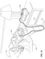
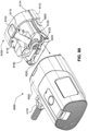
- An exploded view of an RPT device 4000 in accordance with one aspect of the present technology is shown in Fig. 5A .
- An RPT device 4000 may comprise mechanical, pneumatic, and/or electrical components and be configured to execute one or more algorithms.
- the RPT device 4000 may be configured to generate a flow of air for delivery to a patient's airways, such as to treat one or more of the respiratory conditions described elsewhere in the present document.
- the RPT device 4000 is constructed and arranged to be capable of delivering a flow of air in a range of -20 L/min to +150 L/min while maintaining a positive pressure of at least 6 cmH 2 O, or at least 10cmH 2 O, or at least 20 cmH 2 O.
- the RPT device 4000 may have an electrical power supply 4210, one or more input devices 4220, a central controller 4230, a therapy device controller 4240, one or more protection circuits 4250, memory 4260, sensors/transducers 4270, data communication interface 4280 and one or more output devices 4290.
- Electrical components 4200 may be mounted on a single Printed Circuit Board Assembly (PCBA) 4202 (e.g., see Fig. 5A ).
- PCBA Printed Circuit Board Assembly
- the RPT device 4000 may include more than one PCBA 4202.
- an outlet air filter 4114 for example an antibacterial filter, is located between an outlet of the pneumatic block 4020 and a patient interface 3000.
- a pressure generator 4140 may be a piston-driven pump, a pressure regulator connected to a high pressure source (e.g. compressed air reservoir), or a bellows.
- a signal representing a flow rate from the flow rate sensor 4274 is received by the central controller 4230.
- the central controller 4230 may be configured to receive input signal(s) from one or more transducers 4270, one or more input devices 4220, and the humidifier 5000.
- the central controller 4230 may be configured to provide output signal(s) to one or more of an output device 4290, a therapy device controller 4240, a data communication interface 4280, and the humidifier 5000.
- the output values include the interface or mask pressure Pm, the respiratory flow rate Qr, and the leak flow rate QI.
- the leak flow rate estimation algorithm 4316 receives as an input a total flow rate Qt, a vent flow rate Qv, and an estimated pressure, Pm, in the patient interface 3000, and provides as an output a leak flow rate Ql, by calculating a leak conductance, and determining a leak flow rate Ql to be a function of leak conductance and pressure, Pm.
- Leak conductance is calculated as the quotient of low pass filtered non-vent flow rate equal to the difference between total flow rate Qt and vent flow rate Qv, and low pass filtered square root of pressure Pm, where the low pass filter time constant has a value sufficiently long to include several breathing cycles, e.g. about 10 seconds.
- the leak flow rate Ql may be estimated as the product of leak conductance and a function of pressure, Pm.
- a therapy parameter is a treatment pressure Pt.
- Another implementation of discrete phase determination provides a tri-valued phase output ⁇ with a value of one of inhalation, mid-inspiratory pause, and exhalation.
- the central controller 4230 executes an inspiratory flow limitation determination algorithm 4324 for the determination of the extent of inspiratory flow limitation.
- an apnea will be said to have been detected when a function of respiratory flow rate Qr falls below a flow rate threshold for a predetermined period of time.
- the function may determine a peak flow rate, a relatively short-term mean flow rate, or a flow rate intermediate of relatively short-term mean and peak flow rate, for example an RMS flow rate.
- the flow rate threshold may be a relatively long-term measure of flow rate.
- the central controller 4230 executes one or more snore determination algorithms 4326 for the determination of the extent of snore.
- the frequency range within which the peak is sought is the frequency of a small forced oscillation in the treatment pressure Pt.
- the forced oscillation is of frequency 2 Hz with amplitude about 1 cmH 2 O.
- airway patency determination algorithm 4327 receives as an input a respiratory flow rate signal Qr, and determines the presence or absence of a cardiogenic signal. The absence of a cardiogenic signal is taken to be an indication of a closed airway.
- the central controller 4230 takes as input the measure of current ventilation, Vent, and executes one or more target ventilation determination algorithms 4328 for the determination of a target value Vtgt for the measure of ventilation.
- the target ventilation determination algorithm 4328 computes a target value Vtgt from a value Vtyp indicative of the typical recent ventilation of the patient.
- the target ventilation Vtgt is computed as a slightly greater than unity multiple of the typical recent ventilation Vtyp.
- the central controller 4230 executes one or more therapy parameter determination algorithms 4329 for the determination of one or more therapy parameters using the values returned by one or more of the other algorithms in the therapy engine module 4320.
- the therapy parameter is a treatment pressure Pt
- the therapy control module 4330 controls the pressure generator 4140 to deliver a flow of air whose mask pressure Pm at the patient interface 3000 is equal to the treatment pressure Pt.
- the corresponding algorithm 4340 Upon detection of the fault condition, the corresponding algorithm 4340 signals the presence of the fault by one or more of the following:
- a humidifier 5000 (e.g., as shown in Fig. 5C ) to change the absolute humidity of air or gas for delivery to a patient relative to ambient air.
- the humidifier 5000 is used to increase the absolute humidity and increase the temperature of the flow of air (relative to ambient air) before delivery to the patient's airways.
- the humidifier e.g., reservoir dock 6050
- the RPT device e.g., pneumatic block 7100
- additional interfaces may be used to connect the humidifier (e.g., reservoir dock 6050) to the RPT device (e.g., pneumatic block 7100).
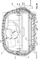
- the pneumatic block 7100 includes a chassis assembly 7300, e.g., including a top chassis and a bottom chassis.
- the chassis assembly 7300 includes a chassis inlet 7310 (e.g., see Fig. 20E ) and a chassis outlet 7320 (e.g., see Figs. 20F and 21 ).
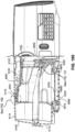
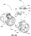
- an external housing 8002 including one or more panels and/or one or more user inputs/displays, may enclose the pneumatic block 7100, e.g., see Figs. 6A and 6B .
- the chassis assembly 7300 supports and/or houses internal components of the pneumatic block 7100, e.g., the blower.
- the chassis assembly 7300 also supports a printed circuit board assembly (PCBA) 7600.
- PCBA printed circuit board assembly
- the air delivery tube is directly or indirectly connectable to a tube engagement dock of the RPT device. All of the above disclosure related to the water reservoir connecting dock is also applicable to the respective tube engagement of the RPT device in such cases.
- connection or engagement port may be located anywhere on the RPT device and/or humidifier, as long as it is communicated (e.g., via one or more intermediate connectors) with the pressurised flow source of the RPT device and/or the humidifier (e.g., water reservoir).
- the connection or engagement port may form part of the water reservoir dock, or may be positioned elsewhere (i.e., not part of the water reservoir dock) and communicated with the water reservoir dock, water reservoir thereof or the pneumatic block of the RPT device.
- Conductive portion including metal plate and/or thin film
- the thin film conductive portion 6150F may comprise a thickness of about 0.05 mm to 1 mm, e.g., 0.10 mm to 0.125 mm. In an example, the thin film may comprise a thickness less than about 1 mm, e.g., 0.5 mm, less than about 0.5 mm, e.g., 0.40 mm, 0.375 mm, 0.25 mm, 0.175 mm, 0.125 mm.
- the conductive portion 6150MF may include a shape corresponding to a shape of the heater plate 6080, e.g., for stability, more efficient thermal conductivity.
- the conductive portion 6150MF and heater plate 6080 may include circular or non-circular shapes, e.g., rectangular, square, oval.
- the conductive portion 6150MF includes a rectangular shape, e.g., corresponding to a shape of the heater plate 6080 within the reservoir dock 6050.
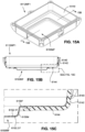
- Figs. 16A to 16C show an alternative example in which reservoir base 6112MF2 includes a circular, conductive portion 6150MF.
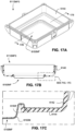
- Figs. 17A to 17C show a reservoir base 6112MF3 including a deeper drawn, rectangular-shaped, conductive portion 6150MF.
- the metal plate/thin film may comprise a generally planar shape, i.e., pre-formed planar shape.
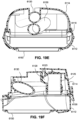
- the reservoir lid 6114 is configured to connect to the reservoir base 6112.
- the configuration may be arranged to allow the water reservoir to be convertible between an open configuration and a closed configuration.
- the reservoir lid 6114 may be hingedly connected to the reservoir base 6112 by hinge pins.
- the reservoir lid 6114 may include a plurality of resilient locking tabs adapted to interlock with the reservoir base 6112, e.g., with a snap-fit.
- a seal 6116 e.g., see Fig.
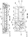
- the inlet tube 6120 When the reservoir lid 6114 is coupled to the reservoir base 6112, the inlet tube 6120 includes an outer (inlet) end 6124 arranged outside the chamber and an inner (outlet) end 6126 arranged inside the chamber.
- the outlet tube 6130 includes an outer (outlet) end 6134 arranged outside the chamber and an inner (inlet) end 6136 arranged inside the chamber.
- Each of the inlet tube or the outlet tube (together with each tube's respective inlet and outlet) may be replaced by an opening in a wall of the reservoir lid.
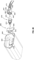
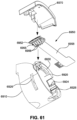
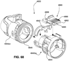
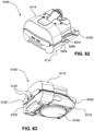
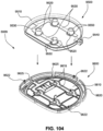
- Fig. 80 illustrate an integrated RPT device and humidifier 6000 according to an example of the present technology similar to that illustrated in Figs. 6A , 6B , 7 and 8A to 8D .
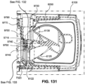
- Figs. 80 , 85 , 86 and 134-136 show a water reservoir 6100 and a reservoir lid 6114 according to another example of the present technology.
- an inlet seal 6122 e.g., bellows-type arrangement
- no seal is provided to the free outer (outlet) end of the outlet tube 6130.
- such a seal may be provided to the inlet of the intermediate element to which the outlet tube 6130 is attached.
- the inlet seal 6122 may be overmolded to the reservoir lid 6114 along with the peripheral seal 6116 arranged to form a seal between the lid 6114 and the base 6112 in use (see Fig. 85 ), e.g., seals 6122, 6116 from integral, once-piece component of elastomeric material. That is, as shown in Fig.
- the reservoir lid 6114 (including the inlet tube 6120 and the outlet tube 6130) may comprise a first part or base mold constructed of a relatively rigid material (e.g., thermoplastic polymer (e.g., PC, ABS)) and the inlet seal 6122 and the seal 6116 may comprise a second part or overmold constructed of a relatively soft material (e.g., thermoplastic elastomer (TPE) or silicone) that is provided (e.g., by overmolding) to the first part.
- a relatively rigid material e.g., thermoplastic polymer (e.g., PC, ABS)
- TPE thermoplastic elastomer
- silicone elastomer
- the water reservoir 6100 may be configured to discourage egress of liquid therefrom, such as when the water reservoir is displaced and/or rotated from its normal, working orientation.
- the inlet tube 6120 can include an outer (inlet) end 6124 arranged outside the chamber and an inner (outlet) end 6126 arranged inside the chamber.
- the inlet tube 6120 includes an inlet portion 6123 including the inlet end 6124 and an outlet portion 6125 including the outlet end 6126.
- the bottom of the water reservoir e.g., the conductive portion 6150
- the bottom of the water reservoir includes a bottom surface defining a bottom plane that is substantially horizontal when the water reservoir is in the normal, working orientation (e.g., see Fig. 19C ). As illustrated in Figs.
- various portions of the inlet tube 6120 may extend in different directions, e.g., change direction at least at one point along its length.
- the inlet portion 6123 extends in a plane that is substantially parallel to the bottom plane
- the outlet portion 6125 extends in a different direction (in this case the outlet portion 6125 extends in a plane that is substantially perpendicular to the bottom plane).
- Various twists and/or turns may be introduced in each portion (orientation) of the inlet tube 6120.
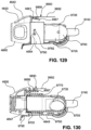
- the outlet tube 6130 can include an outer (outlet) end 6134 arranged outside the chamber and an inner (inlet) end 6136 arranged inside the chamber. Similar to the inlet tube, the outlet tube can also extend in different directions, e.g., change direction at least at one point along its length. Also similar, the outlet tube 6130 can include a vertical twist (a bend in the plane that is substantially perpendicular to the bottom plane) such that the outlet tube 6130 curves downwardly from the outlet end 6134 to the inlet end 6136, which allows the outlet tube 6130 to cross under the inlet portion 6123 of the inlet tube 6120. Further, the opening at the inlet end 6136 of the outlet tube 6130 is curved upwards to prevent spitting (which happens when water is pushed out of the outlet tube due to pressure and flow).
- outlet end 6126 of the inlet tube 6120 and the inlet end 6136 of the outlet tube 6130 may be arranged at or near the geometric center or centroid of the reservoir chamber.
- Fig. 19C shows inlet end 6124, outlet end 6126, outlet end 6134 and inlet end 6136 all above the water level in the working orientation
- Fig. 19D shows outlet end 6126 and outlet end 6134 above the water level when the water reservoir is rotated by 90 degrees front
- Fig. 19D shows inlet end 6124 and inlet end 6136 above the water level when the water reservoir is rotated by 90 degrees back
- Fig. 19G shows at least the outlet end 6126 above the water level when the water reservoir is rotated by 180 degrees.
- Such arrangement achieves spillback protection to discourage water from entering the inlet and outlet tubes of the water reservoir at various orientations.
- Fig. 19G shows at least the outlet end 6126 above the water level when the water reservoir is rotated by 180 degrees.
- the spillback feature involves the inlet and outlet tubes 6120, 6130 having their outlet end 6126/inlet end 6136 being located in the middle of the water reservoir (e.g., at or near the geometric center or centroid of the reservoir chamber), so that upon an accidental tumbling of the water reservoir in various angles, when the water reservoir still includes a certain amount of water, the level of that water stays mostly below the level of these centrally located outlet end 6126/inlet end 6136 of the inlet and outlet tubes 6120, 6130. This is where the curved shape of the tubes can help.
- the other tube may not simply extend below the first tube (and therefore move away from the central area of the water reservoir), but can be directed to bend below the first tube and then curve back to any desired level.
- the tubes may simply cross each other at different levels.
- Such a design can define two sides of the reservoir for which, when the reservoir is tilted on one of these sides, one of the inlet or the outlet tube is inclined upwardly, thus keeping the respective in-tub opening above the water level. In this case the other tube would be inclined downwardly and the in-tub opening may be exposed to the water, unless mitigation measures have been taken.
- the curved design of the present technology may mitigate this problem.
- the curvature of the inlet tube 6120 and/or the outlet tube 6130 may be a shallow or a significant curvature.
- the curvature can also be in more than one plane, in order to optimize the inner space of the tub.
- the concept of curving the tubes may be further enhanced by introducing a second curvature, subsequent to the first one, which may change the direction, or at least the radius, of the first curvature.
- the premise behind such shapes is that they can introduce further resistance to a propagation of water in some direction.
- such consecutive "kinks" that extend in one or more planes/directions can provide resistance in the respective one or more directions, and therefore protect against tumbling/rolling over/flipping of the reservoir.
- the benefit can be weighed against the complexity of the design and the resistance provided to the airflow.
- the inlet tube 6120 and/or the outlet tube 6130 may comprise a different material (e.g., more flexible material) than the reservoir lid, e.g., silicone or TPE to facilitate bending into the desired configuration.
- the inlet tube 6120 and/or the outlet tube 6130 may comprise a similar material to the reservoir lid, e.g., polycarbonate.
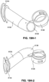
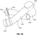
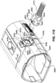
- Figs. 19H-1 and 19H-2 show a removable outlet tube arrangement for a water reservoir according to an example of the present technology.
- the removable outlet tube arrangement includes the outlet tube 6130 and a portion of the inlet tube 6120, e.g., an outlet end 6126 of the inlet tube 6120.
- the inlet portion 6123 and the outlet portion 6125 of the inlet tube 6120 may be formed, e.g., molded, as a part of the reservoir lid 6114.
- the removable outlet tube arrangement is formed as a separate and distinct structure from the reservoir lid 6114 and then secured or otherwise assembled to the reservoir lid 6114 to form complete inlet and outlet air paths.
- Figs. 19A to 19G show the removable outlet tube arrangement secured to the reservoir lid 6114 in an operative position.
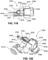
- Fig. 19I shows an alternative example in which the inlet tube 6120 and the outlet tube 6130 comprise a removable inlet tube and outlet tube arrangement that is a separate and distinct structure from the reservoir lid 6114 and then secured or otherwise provided to the reservoir lid 6114 in an operative position.
- Figs. 82 to 97 show a water reservoir 6100 including reservoir lid 6114 hingedly and removably coupled to the reservoir base 6112 according to an example of the present technology.
- the water reservoir 6100 comprises a hinge joint between the lid 6114 and the base 6112 which allows the lid 6114 to hingedly move between an open position (see Figs. 84 and 89 ) and a closed position (see Figs. 82, 83 , and 91 ).
- Each hinge pin 9105 (see Fig. 87 ) includes a segmented cylindrical shape comprising a cylindrical surface 9105c to provide hinged movement, and a flat surface 9105f - to facilitate engagement/disengagement of each hinge pin 9105 with/from a respective open-ended slot 9200 (see Fig. 88 ). That is, as shown in Fig. 90 , the cross-section of each hinge pin 9105 represents a major segment of a circle.
- each hinge pin 9105 is oriented generally horizontally, which allows the smaller width (or diameter) of the major segment cross-section of the hinge pin 9105, which extends from the flat surface 9105f to the opposing cylindrical surface 9201c, to engage with the open end 9200o of the slot 9200, thereby allowing the hinge pin 9105 to pass relatively easy through the open end 9200o into the interior of the slot 9200.
- the smaller width of the major segment provided by each of the pair of hinge pins is larger than an opening of the open end or side of the respective one of the pair of slots, so that even when aligned, force has to be applied to lever the pair of hinge pins out of the pair of slots, by causing each opening to flex out and release a respective one of the pair of hinge pins.
- the slots 9200 hingedly retain respective hinge pins 9105 to allow the lid 6114 to hingedly move between the open position (see Figs. 89 and 90 ) and the closed position (see Figs. 91 and 92 ).
- the lid 6114 is over-extended or hingedly moved beyond the fully open position (i.e., further than the rotation stop provided by the stop member 9110).
- the fully open position the smallest dimension of the segmented cross-section of the hinge pins is generally aligned with the opening 9200o in the respective slots.
- the stop member 9110 engaged with the side wall 9210 starts to act as a cantilever and push the hinge pins towards the opening 9200o. This causes the opening 9200o to flex and release the hinge pins 9105 out of respective slots 9200.
- the openings 9200o and the segmented cross-sections of the hinged pins are not strictly needed, as a continuous push backwards would eventually allow the stop member 9110 to lever the hinge pins out of the slots 9200, even without the openings or the segmented cross-section.
- having the openings and having the smaller width or diameter of the major segment provided by the hinge pins 9105 arranged at the open end 9200o of the slot 9200 when the lid 6114 is over-extended does make the disengagement of the lid easier, i.e., the flat surface 9105f of the hinge pin 9105 reduces stress on the hinge when pulling or popping it out of the slot 9200.
- providing the opening 9200o changes the location of accumulated stress.
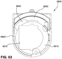
- the reservoir dock 6050 is provided to the chassis assembly 7300 of the RPT device and configured and arranged to receive the water reservoir 6100.
- the reservoir dock 6050 may comprise a locking feature such as a locking lever or tab, configured to retain the water reservoir 6100 in the reservoir dock 6050.
- the main body of the reservoir dock 6050 comprises a plurality of walls and a heating element (e.g., heater plate 6080) provided to a bottom one of the walls to form the cavity to receive the water reservoir 6100.
- a heating element e.g., heater plate 6080
- Removing the RPT device and the reservoir dock 6050 from the air delivery path eliminates the presence of an internally located coupling component between the water reservoir 6100 and the air delivery conduit 4170. This eliminates the need to disassemble and sterilize such coupling component, thus making sterilization much easier. In this way, when preparing the device for a different user, the water reservoir 6100 is the only component of the RPT device which needs to be replaced or sterilized.
- an outer side portion of the water reservoir 6100 provides a dock engagement portion structured and arranged to interface and engage a reservoir engagement portion of the reservoir dock 6050.
- the water reservoir 6100 and reservoir dock 6050 may include guiding structures to facilitate insertion, removal, and alignment of the water reservoir 6100 with the reservoir dock 6050.
- the water reservoir 6100 may be inserted/removed (e.g., by sliding or push/pull only) along a path extending in a lateral direction (i.e., anterior-posterior direction) into and out of the cavity of the reservoir dock 6050.
- a lateral direction i.e., anterior-posterior direction
- each side of the reservoir dock 6050 includes a guide slot 6060 configured to receive a respective guide protrusion or pin 6250 on each side of the water reservoir 6100.
- each guide slot 6060 includes a generally horizontal section 6060H extending in anterior-posterior direction leading to a drop down section 6060D that slopes downwardly from the generally horizontal section 6060H in an inferior direction.
- the first, heat conducting portion 6150.1 of the conductive portion 6150 of the water reservoir 6100 engages and slides along the upper guide surface 7355 of the front ledge 7350 supporting the heating element 6085 (e.g., see Fig. 27A ).
- the first, heat conducting portion 6150.1 of the water reservoir 6100 also clears the internal edge of the front ledge 7350, which allows the water reservoir 6100 and the first, heat conducting portion 6150.1 thereof to drop down into engagement with the heating element 6085 (e.g., see Figs. 25A , 26B , and 27B ).
- the stepped arrangement of the conductive portion 6150 of the water reservoir 6100 is configured to allow the first, heat conducting portion 6150.1 to drop down into engagement with the recessed heating element 6085 while the second (usually not heat-conducting) portion 6150.2 drops down into engagement with the front ledge 7350 (e.g., see Fig. 27B ).
- Such drop down engagement configuration effectively locks the water reservoir 6100 in an operative position, i.e., the front ledge 7350 provides a guide surface 7355 and also allows the water reservoir 6100 to engage therebehind to lock the water reservoir 6100 in position and prevent unintended release, e.g., during treatment, when the entire system is under pressure which may push the water reservoir out of its operational configuration.
- the engagement portion of the bottom surface of the water reservoir 6100 engages over a much smaller surface of the bottom of the dock, thus reducing wear and potential damage to the water reservoir 6110 (i.e., its conductive portion 6150) and the heater plate.
- the heating element 6085 may be provided without a heater plate (also referred to as a wear plate or skid plate, e.g., formed of hard metallic material) along its upper or superior surface to protect the heating element 6085. That is, such engagement configuration allows the conductive portion 6150 of the water reservoir 6100 to directly engage the heating element 6085 such that heat is directly transferred from the heating element 6085 to the volume of liquid in the water reservoir 6100, i.e., thereby improving thermal conductivity as heat does not need to pass through a heater plate or skid plate. Such an arrangement can also be more cost effective.
- each guide slot 6060 includes an additional, generally horizontal section 6060H2 extending from the drop down section 6060D.
- the first, heat conducting portion 6150.1 of the conductive portion 6150 of the water reservoir 6100 may be reduced in size such that the first, heat conducting portion 6150.1 does not fill the recessed space provided by the recessed heating element 6085, e.g., to allow horizontal movement.
- Such an engagement locks the front end of the water reservoir 6100, when fully inserted inside the dock 6050, as well as biases downwardly the water reservoir 6100 in order to enhance abutment of its conductive portion 6150 with the heater plate 6080 of the heating assembly 6075 provided at the bottom of the reservoir dock 6050 (see Figs. 100 and 101 ).
- the downward push of the slots 6060 onto respective rails 6200 (which are located at an intermediate to rear portion of the water reservoir 6100, with the front end being the end arranged to firstly engage with reservoir dock 6050) is complimented by a downward push exerted by the abutment edges 9450 onto respective biasing tabs 9320 at the front or leading side of the water reservoir 6100.
- the abutment edges 9450 engage the upwardly oriented surface 9325 of respective biasing tabs 9320 (see Fig. 101 ) close to the end of the engagement process, when the water reservoir 6100 is almost fully inserted into the reservoir dock 6050.
- the slots 6060 and the abutment edges 9450 are arranged to be generally horizontal (e.g., generally parallel to the heater plate 6080), which arrangement allows the water reservoir 6100 to be inserted/removed (e.g., by sliding or push/pull only) along a path extending in a lateral direction (i.e., anterior-posterior direction) into and out of the cavity of the reservoir dock 6050.
- a lateral direction i.e., anterior-posterior direction
- at least a portion of the slots 6060 and/or the abutment edges 9450 may include a slope, such that at least a portion of the path for insertion/removal may extend in an inferior/superior direction.
- the water reservoir 6100 may be compressed (i.e., by depressing the lid 6114 against the base 6112) to compress the deformable seal 6116 and allow the protrusions 6115 to lower or drop beneath the forward end of the recess 6051.
- Such a locking arrangement ensures that the positive pressure inside the assembled RPT device, when in its operational configuration, does not push the water reservoir backwards and out of operational engagement with the reservoir dock 6050, thus ensuring a reliable operation of the device.
- the water reservoir 6100 may comprise a latch 6400 configured to releasably engage with a recessed slot 6055 in the reservoir dock 6050 to releasably retain the water reservoir 6100 in an operative position within the reservoir dock 6050.
- a locking arrangement prevents the water reservoir from disengaging from the dock, which in some arrangements, the water reservoir may be encouraged to do by the relatively high operational pressure within the dock during the operation of the device.
- the dock connector 4600 includes a tubular base portion 4640 and a locking and contact assembly 4660 provided to the base portion 4640.
- the locking and contact assembly 6900 may include a stop wall 6935 (see Fig. 70 ) arranged to engage the locking and contact assembly 4660 of the dock connector 4600 when the dock connector 4600 reaches the locked position to prevent further rotation of the dock connector 4600, e.g., see Fig. 74 .
- the intermediate component 9700 may also include a guide rail 9760 (along a lower side of the intermediate component 9700) and a guide rib 9761 (along a forward, upper side of the intermediate component 9700) structured and arranged to assist in correct alignment and insertion of the intermediate component 9700 into the reservoir dock 6050 by engagement with corresponding guide slots 9755 extending into the cavity of the reservoir dock 6050 (e.g., see Figs. 114 , 115B , 116, 117 ).
- an external housing or outer shroud 8050 (enclosing the chassis assembly 7300 and reservoir dock 6050) provides a cover or enclosure for the contact assembly 9950, and forms a socket or opening 9980 leading to the contacts 9955 (female connector) for engagement with respective contacts of the dock connector 4600 (male connector).
- a tapered protrusion 4642 protrudes outwardly from the base portion 4640 (see Fig. 123 ) adjacent the contact assembly 4661.
- the tapered protrusion 4642 provides a thumb and/or finger grip to facilitate manual manipulation and connection of the dock connector 4600 with the intermediate component 9700 and the contact assembly 9950 provided to the reservoir dock 6050.
- the tapered protrusion 4642 may include an alignment marking that is configured and arranged to align with an alignment marking provided to the reservoir dock 6050 when the air delivery tube 4170 is connected to the reservoir dock 6050, to ensure correct alignment and proper connection of the dock connector 4600 of the air delivery tube 4170 to the reservoir dock 6050 in use.
- the contact assembly 4661 (lead frame) includes a support portion 4665 and a plurality of contacts 4667, e.g., four contacts, included along a front side of the support portion 4665.
- the support portion 4665 includes a step-shaped configuration to support the contacts 4667 in spaced relation from the base portion 4640.
- the contacts 4667 are arranged to engage with respective contacts 9955 provided to the contact assembly 9950 on the reservoir dock 6050 to form electrical and control signal connections with the reservoir dock 6050.
- the dock connector 4600 may comprise a base assembly 4680 (including a base 4682 and a cover 4684) that supports the contact assembly 4661 (lead frame).
- the contact assembly 4661 may first be engaged or interlocked with the base 4682, and then the cover 4684 may be clipped onto or otherwise engaged with the base 4682 to securely support and retain the contact assembly 4661 in an operative position.
- the dock connector 4600 may be pulled outwardly away from the reservoir dock 6050 with sufficient force to release the retaining bumps 4644 from respective holes 9792.
- Fig. 35A shows a schematic view of a dock and a tube connection in accordance with one form of the present technology.
- the dock outlet 6090 may include a contact assembly 6800 that can be coupled to a corresponding contact assembly 4172 of the tube 4170 via four connections.
- the dock outlet 6090 may be mechanically and electrically coupled to the tube 4170.
- the heater control circuit may supply power to heating element in the tube 4170 via a switch (e.g., a transistor).
- the heater control circuit may control the duration, voltage, and/or frequency and/or period of Pulse Width Modulation (PWM) signal supplied to the heating elements in the tube 4170.
- PWM Pulse Width Modulation
- the sensing circuit may measure voltage and/or current of the transducer to determine the operating characteristics (e.g., temperature) of the heating elements.
- the heater control circuit may control the heating elements based on the signals received by the sensing circuit and the settings sets for the heating tube 4170.
- Other sensors disposed anywhere in the tube, i.e., humidity sensors, may also be connected in a similar way.
- the settings may be modified based on the size of the identified air delivery tube (e.g., 15mm, 19 mm), presence and type of HME, type of patient interface connected to tube, etc..
- the type of tube that is connected to the dock 6050 may be determined by the sensing circuit based on unique electrical characteristic(s) provided by active and/or passive components in the tube 4170 via one or more of the four connectors.
- first circuit element 8022 is coupled to two pins in tube 4170 and a second circuit element 8024 is coupled to two other pins in the tube 4170. While single circuit elements are shown in Fig. 35A , first and/or circuit elements may include a plurality of active and/or passive circuit elements.
- the second circuit element 8024 may include a sensor in the form of a thermistor formed of a Negative Temperature Coefficient (NTC) material.
- the parameters of the second circuit element 8024 e.g., resistance
- the sensing circuit may be configured to sense the temperature of the tube 4170 by monitoring changes in the parameters of the second circuit element 8024.
- Fig. 35B shows circuit diagram of the dock and tube connection in accordance with one form of the present technology.
- the first circuit element 8022 in Fig. 35A may be represented by two resistors 5R (with approximately 5 ohms) coupled to the Heater + and Heater - connections. This is associated with the fact that the heating wire usually comprises one or more (usually two) copper wires connected sequentially to each other and having a total resistance of about 10 ohms. The combined length of wire extends from the dock coupling end of the tube to the mask coupling end of the tube and back to the dock coupling end of the tube.
- the second circuit element 8024 in Fig. 35A may be represented by a thermistor and two resistors 5R coupled to the NTC+ and NTC- connections.
- the thermistor in Fig. 35A may be selected based on the type of air tube.
- a 10k thermistor may be provided in a 15mm air tube
- a 100k thermistor may be provided in a 19mm air tube
- an open circuit may be provided in a passive air tube.
- the example shown in Fig. 36 includes the first and second circuit elements 8022 and 8024 in the adapter. Only in this case these circuit elements do not represent the resistance of a heater wire and of a NTC sensor/transducer, but include simple resistors that are detected by the controller in order to identify the connection of a passive tube to the system. As shown schematically in Figs. 24A-B , the first and second circuit elements 8022 and 8024 may be provided in a housing including the connections. The first and second circuit elements 8022 and 8024 may directly connect to the connections provided in the adaptor 8020.
- the first and second circuit elements in the adapter allow for the sensing circuit in the humidifier to determine the type of tube connected to the dock 6050. This is different from the example in Fig. 35A , where characteristics of circuitry including the heating element and/or the sensor (e.g., provided in the tube) are used to determine the type of type connected to the system. Because of that, the value of the first and second circuit elements in this example of a passive tube needs to be selected so that it is outside of the range of values that would be expected from first and second circuit elements of the active tube in Fig. 35A . As would be discussed below, the specific electrical characteristics (i.e., resistance) of the NTC element has to be considered in working environment where it may spread over a broad range of values.
- Fig. 38 shows a schematic view of a dock and a tube connection in accordance with another form of the present technology.
- the example shown in Fig. 38 is similar to the example shown in Fig. 36 , but only uses a single circuit element (e.g., 36K resistor) in the adapter to reduce the cost of goods in the adapter.
- the number of connections in the adapter are also decreased.
- the reliability of the detection may be somewhat diminished, as the combination of 36K value of NTC and open circuit of the Heater wire may also represent the situation of either double fault in the tube (NTC partial crack on NTC wire + open circuit on heater wire) or the case of the contaminated NTC terminals with the passive tube connected mechanically via ISO taper.
- the air delivery tube 4170 may comprise four wires, e.g., two wires for heating elements and two wires for a transducer, e.g., negative temperature coefficient (NTC) thermistor used as a temperature sensor.
- NTC negative temperature coefficient
- NTC is only one of a plurality of different types of temperature sensors known to a skilled addressee.
- the signal at VH (V high) and VL (V low) points is provided to the microcontroller configured to subtract the V low from the V high.
- the difference between the V low and V high indicates the resistance of the sensor 9030.
- the microprocessor is configured to track the changes in resistance of the sensor 9030 due to changes in the temperature of the tube 4170 and determine operation setting for components of the system (e.g., heating elements in the tube 4170).
- the probing of the sensor 9030 may be timed at intervals that are not synchronized with the PWM signal.
- the probing of the sensor 9030 is slower than the period of the PWM signal.
- the probing period may be several seconds. The probing period may change depending on the circumstances. For example, in some instances the probing may be constant, whilst in others, a probing of several seconds may be used for the time periods when it is detected that there is no tube connected to the dock, however a shorter period, or even a continuous monitoring, may be used once it is detected that there is a tube connected to the device.
- the signal for probing the sensor 9030 is provided as a DC signal.
- a first low pass filter LPF1 is coupled to the RHigh resistor and connection VH-Lpf and a second low pass filter LPF2 is coupled to the Rlow resistor and the connection VL-Lpf.
- Each filter may be formed as a single component (i.e., a capacitor) or a combination of active (i.e., operational amplifiers) and/or passive (resistor/capacitors) electronic components. For example, when a large capacitor (tens of nF) is used for each of LPF1 and LPF2, the cross-talk between the wires of the heated tube and the sensor is largely mitigated even without the use of LPF3 and/or LPF4.
- the sensor 9030 supply (for the divider) Vsense is generally turned off, but is turned on and off periodically to detect if the tube 4170 is connected. When it is detected that the tube 4170 is not connected, the supply to the sensor 9030 is turned off again. Turning off the supply may reduce corrosion in the connections in the humid environment in which they may be operating.
- the water reservoir 6100 may comprise a water level indicator.
- the water level indicator may provide one or more indications to a user such as the patient 1000 or a care giver regarding a quantity of the volume of water in the water reservoir.
- the one or more indications provided by the water level indicator may include an indication of a maximum of a predetermined volume of water, as well as any portions thereof, such as 25%, 50% or 75%, or volumes such as 200 ml, 300 ml or 400ml.
- the heating element may be subdivided or partitioned into vertically distributed zones/sections.
- Each of the zones/sections may be controlled independently to independently switch on/off and control the temperature of each of the zones/sections and to deactivate when not heating (i.e., when water level has dropped and an upper portion of the heater is no longer in contact with water). This can lead to an efficient use of energy to only heat the zones/sections that are in contact with water.
- each of the zones/sections may be associated with a respective sensor.
- the distribution in vertical direction of a number of sensors allows detecting the water level to provide an indication to the patient regarding a quantity of the volume of water in the water reservoir, e.g., without the patient having to directly view the water level in the water reservoir.
- a number of sensors such as NTC-type sensors
- Such arrangement may allow the use of a water reservoir having non-transparent side walls, e.g., non-clear plastic or metal side walls, as the water level does not need to be directly viewed through a side wall of the water reservoir.
- the heating element may include a PCB with printed resistive tracks. Such an arrangement allows for easy partitioning of the track, thus defining different heating zones.
- a vertically orientated distributed temperature sensor or a number of discrete sensors, may be used to indicate if a level is inside water or not.
- One or more flow rate transducers 5214 may be provided to the humidifier 5000 in addition to, or instead of, a flow rate sensor 4274 provided in the RPT device.
- the humidifier 5000 may comprise one or more temperature transducers 5216.
- the one or more temperature transducers 5216 may be configured to measure one or more temperatures such as of the heating element 5240 and/or of the flow of air downstream of the humidifier outlet.
- the humidifier 5000 may further comprise a temperature sensor 5216 to detect the temperature of the ambient air.
- a heater plate 6080 is used to transfer heat to the water reservoir.
- the heater plate may form a part of the reservoir dock 6050, and may be located on or near the base of the reservoir dock. At least the top layer of the heater plate comprises a hard scratch resistant surface that may be formed, for example, of a nickel chrome alloy, stainless steel or anodised aluminium.
- the heater plate may transfer heat from a heating element.
- the heating element may comprise a heat generating component such as an electrically resistive heating track.
- One suitable example of a heating element is a layered heating element such as one described in the PCT Patent Application Publication No. WO 2012/171072 , which is incorporated herewith by reference in its entirety.
- one or more support cones 6098 e.g., see Figs. 34A and 34C
- tubes e.g., see Figs. 103 and 104
- the thermal pad is preferably made by a pliable or compliant thermo-conductive material and is arranged between the heater plate 6080 and the heating element 6085 (e.g., engages or sticks (e.g., bonds) to both the heater plate and the heating element).
- the thermal pad can fill the air gaps or spaces between heater plate 6080 and the heating element 6085, which enhances thermal conductivity from the heating element 6085 to the heater plate 6080.
- both the heater plate 6080 and the heating element 6085 typically include planar surfaces made of a hard material, any small imperfections on the surfaces may cause air gaps between these two surfaces. Having the pliable layer between these surfaces helps with removing such air gaps and improving the thermal conductivity of the system.
- the support structure 6089 includes a resilient sealing and supporting member 9500 and a base plate 9600 to support the resilient sealing and supporting member 9500 at the bottom of the reservoir dock 6050 (see Fig. 104 ).
- the resilient sealing and supporting member 9500 e.g., constructed of an elastomeric material (e.g., silicone)
- the bias keeps the heater plate 6080 and the conductive portion 6150 pressed against each other to enhance thermal conductivity between them.
- the peripheral lip 9510 When provided to the base plate 9600, the peripheral lip 9510 is configured to extend on the inner side of the peripheral flange 9620 in a substantially upward (with respect to the operation configuration of the device) direction (see Fig. 106 ), with some possible slight outward flaring in the upper portion of the flange. In an example, the peripheral lip 9510 may extend concentrically to the peripheral flange 9620 (see Fig. 103 ).
- Each of the hollow tubes 9520 includes one end supported by the base surface 9610 and an opposite end configured to engage the heater 6085 when the heating assembly 6075 is assembled to the reservoir dock 6050 (see Fig. 106 ).
- the resilient sealing and supporting member 9500 may be either removably, or permanently attachable to the base surface 9610 of the base plate 9600, e.g., by way of adhesive, over-molding, etc.
- the base 6880 includes a first side that forms an exterior or base surface 6882 adapted to engage the conductive portion 6150 of the water reservoir 6100 in use.
- a second side of the base 6880 forms an interior surface 6884 engaged with the thermal pad 6088 (see Fig. 106 ).
- the base 6880 comprises a generally planar shape configured to extend substantially horizontally when the integrated RPT device and humidifier 6000 is in an operational configuration.
- the skirt 6885 may be horizontal (a simple extension of the base 6880), but is preferably sloped or angled generally downwardly and generally outwardly with respect to the base 6880.
- the skirt can, thus, be formed by a single portion extending downwardly and outwardly from the base 6880.
- the skirt 6885 includes a vertical portion 6885v that extends substantially vertically with respect to the base 6880, which leads to a horizontal portion 6885h that extends in a substantially horizontal plane to that of the base 6880 (see Figs. 103 and 106 ).
- the resilient sealing and supporting member 9500 resiliently supports the heater plate 6080 (along with the heater 6085 and the thermal pad 6088) such that the base 6880 protrudes through the opening in the bottom wall 6053 and the horizontal portion 6885h of the skirt 6885 engages underneath the bottom wall 6053 which provides a hard stop to retain the heater plate 6080 within the opening (see Fig. 106 ).
- the heater 6085 and the thermal pad 6088 are arranged within a pocket of the heater plate 6080 formed by the base 6880 and the vertical portion 6885v of the skirt 6885.
- One side of the heater 6085 is engaged with the hollow tubes 9520 within the boundaries of the peripheral lip 9510, and the opposite side of the heater 6085 is engaged with the thermal pad 6088 which engages the interior surface 6884 of the base 6880.
- some or all of the supporting members in this case - vertical hollow tubes 9520 may be engaged directly with the interior surface 6884 of the base 6880.
- the peripheral lip 9510 of the resilient sealing and supporting member 9500 engages underneath the horizontal portion 6885h of the skirt 6885 of the heater plate 6080.
- the heater plate 6080 is supported in two ways, i.e., along its periphery (the horizontal portion 6885h) by the peripheral lip 9510, and along its central base 6880 by the hollow tubes 9520.
- Figs. 105 and 106 show the heating assembly 6075 when the water reservoir 6100 is removed from the reservoir dock 6050
- Figs. 107 and 108 show the heating assembly 6075 when the water reservoir 6100 is inserted into the reservoir dock 6050.
- the resilient sealing and supporting member 9500 is so configured that, when depressed, it resiliently deflects (e.g., the peripheral lip 9510 curls along its length and the side wall of each hollow tube 9520 buckles radially outwardly), which resilient deflection provides the upward biasing force to bias the heater plate 6080 upwardly against the conductive portion 6150 of the water reservoir 6100.
- the normal displacement of the heater plate 6080 caused by the insertion of the water reservoir 6100 is about 1-2 mm (i.e. how much the heater plate 6080 is pushed down from its rest or stopped position in Figs. 105-106 when the water reservoir 6100 is inserted). Displacement is at least greater than 0 mm to ensure interference of the heater plate 6080 with the conductive portion 6150 of the water reservoir 6100.
- the resilient sealing and supporting member 9500 may include a nominal pre-load when the water reservoir 6100 is removed from the reservoir dock 6050. In an example, the pre-load and/or the displacement may be adjusted by the edge height or thickness of the bottom wall 6053 of the dock 6050 which provides a stop or end of travel for the heater plate 6080.
- each tube essentially acts as a spring, the formation of vacuum in a tube may change the reaction force applied by the tube to the heater, and therefore, to the heated base of the humidification reservoir.
- the formation of (potentially) different degrees of vacuum in one or more tubes (springs) can cause various response pressure to be applied to different points across the surface of the heater. This can potentially cause various degrees of thermal contact between the heater and the water reservoir base, across the area of the heater/base, which may result in a reduction in humidification performance.
- the inclusion of cut-outs or openings in the side wall of the cylinders can minimise the variation in the hollow tubes spring force, resulting in better humidification performance.
- a humidifier 5000 may comprise a humidifier controller 5250 as shown in Fig. 5G .
- the humidifier controller 5250 may be a part of the central controller 4230.
- the humidifier controller 5250 may be a separate controller, which may be in communication with the central controller 4230.
- the humidifier controller 5250 may receive as inputs measures of properties (such as temperature, humidity, pressure and/or flow rate), for example of the flow of air, the water in the reservoir 5110 and/or the humidifier 5000.
- the humidifier controller 5250 may also be configured to execute or implement humidifier algorithms and/or deliver one or more output signals.
- the humidifier controller 5250 may comprise one or more controllers, such as a central humidifier controller 5251, a heated air circuit controller 5254 configured to control the temperature of a heated air circuit 4171 and/or a heating element controller 5252 configured to control the temperature of a heating element 5240.
- Fig. 4 shows a model typical breath waveform of a person while sleeping.
- the horizontal axis is time, and the vertical axis is respiratory flow rate.
- a typical breath may have the following approximate values: tidal volume Vt 0.5L, inhalation time Ti 1.6s, peak inspiratory flow rate Qpeak 0.4 L/s, exhalation time Te 2.4s, peak expiratory flow rate Qpeak -0.5 L/s.
- the total duration of the breath, Ttot is about 4s.
- the person typically breathes at a rate of about 15 breaths per minute (BPM), with Ventilation Vent about 7.5 L/min.
- a typical duty cycle, the ratio of Ti to Ttot is about 40%.
- Air In certain forms of the present technology, air may be taken to mean atmospheric air, and in other forms of the present technology air may be taken to mean some other combination of breathable gases, e.g. atmospheric air enriched with oxygen.
- ambient In certain forms of the present technology, the term ambient will be taken to mean (i) external of the treatment system or patient, and (ii) immediately surrounding the treatment system or patient.
- ambient humidity with respect to a humidifier may be the humidity of air immediately surrounding the humidifier, e.g. the humidity in the room where a patient is sleeping. Such ambient humidity may be different to the humidity outside the room where a patient is sleeping.
- CPAP Continuous Positive Airway Pressure
- Respiratory pressure therapy in which the treatment pressure is approximately constant through a respiratory cycle of a patient.
- the pressure at the entrance to the airways will be slightly higher during exhalation, and slightly lower during inhalation.
- the pressure will vary between different respiratory cycles of the patient, for example, being increased in response to detection of indications of partial upper airway obstruction, and decreased in the absence of indications of partial upper airway obstruction.
- Flow rate The volume (or mass) of air delivered per unit time. Flow rate may refer to an instantaneous quantity. In some cases, a reference to flow rate will be a reference to a scalar quantity, namely a quantity having magnitude only. In other cases, a reference to flow rate will be a reference to a vector quantity, namely a quantity having both magnitude and direction. Flow rate may be given the symbol Q . ⁇ Flow rate' is sometimes shortened to simply 'flow' or ⁇ airflow'.
- a flow rate may be nominally positive for the inspiratory portion of a breathing cycle of a patient, and hence negative for the expiratory portion of the breathing cycle of a patient.
- Total flow rate, Qt is the flow rate of air leaving the RPT device.
- Vent flow rate, Qv is the flow rate of air leaving a vent to allow washout of exhaled gases.
- Leak flow rate, Ql is the flow rate of leak from a patient interface system or elsewhere.
- Respiratory flow rate, Qr is the flow rate of air that is received into the patient's respiratory system.
- Humidifier The word humidifier will be taken to mean a humidifying apparatus constructed and arranged, or configured with a physical structure to be capable of providing a therapeutically beneficial amount of water (H 2 O) vapour to a flow of air to ameliorate a medical respiratory condition of a patient.
- H 2 O water
- Leak The word leak will be taken to be an unintended flow of air. In one example, leak may occur as the result of an incomplete seal between a mask and a patient's face. In another example leak may occur in a swivel elbow to the ambient.
- Conducted noise in the present document refers to noise which is carried to the patient by the pneumatic path, such as the air circuit and the patient interface as well as the air therein.
- conducted noise may be quantified by measuring sound pressure levels at the end of an air circuit.
- Vent noise in the present document refers to noise which is generated by the flow of air through any vents such as vent holes of the patient interface.
- Patient A person, whether or not they are suffering from a respiratory condition.
- Pressure Force per unit area. Pressure may be expressed in a range of units, including cmH 2 O, g-f/cm 2 and hectopascal. 1 cmH 2 O is equal to 1 g-f/cm 2 and is approximately 0.98 hectopascal. In this specification, unless otherwise stated, pressure is given in units of cmH 2 O.
- Respiratory Pressure Therapy The application of a supply of air to an entrance to the airways at a treatment pressure that is typically positive with respect to atmosphere.
- Silicone or Silicone Elastomer A synthetic rubber.
- a reference to silicone is a reference to liquid silicone rubber (LSR) or a compression moulded silicone rubber (CMSR).
- LSR liquid silicone rubber
- CMSR compression moulded silicone rubber
- SILASTIC included in the range of products sold under this trademark
- Another manufacturer of LSR is Wacker.
- an exemplary form of LSR has a Shore A (or Type A) indentation hardness in the range of about 35 to about 45 as measured using ASTM D2240.
- Polycarbonate a thermoplastic polymer of Bisphenol-A Carbonate.
- Hardness The ability of a material per se to resist deformation (e.g. described by a Young's Modulus, or an indentation hardness scale measured on a standardised sample size).
- Stiffness (or rigidity) of a structure or component The ability of the structure or component to resist deformation in response to an applied load.
- the load may be a force or a moment, e.g. compression, tension, bending or torsion.
- the structure or component may offer different resistances in different directions.
- Floppy structure or component A structure or component that will change shape, e.g. bend, when caused to support its own weight, within a relatively short period of time such as 1 second.
- an I-beam may comprise a different bending stiffness (resistance to a bending load) in a first direction in comparison to a second, orthogonal direction.
- a structure or component may be floppy in a first direction and rigid in a second direction.
- Breathing rate The rate of spontaneous respiration of a patient, usually measured in breaths per minute.
- Duty cycle The ratio of inhalation time, Ti to total breath time, Ttot.
- Expiratory portion of a breathing cycle The period from the start of expiratory flow to the start of inspiratory flow.
- hypopnea is taken to be a reduction in flow, but not a cessation of flow.
- a hypopnea may be said to have occurred when there is a reduction in flow below a threshold rate for a duration.
- a central hypopnea will be said to have occurred when a hypopnea is detected that is due to a reduction in breathing effort.
- hypopneas either of the following may be regarded as being hypopneas:
- Patency The degree of the airway being open, or the extent to which the airway is open. A patent airway is open. Airway patency may be quantified, for example with a value of one (1) being patent, and a value of zero (0), being closed (obstructed).
- PEEP Positive End-Expiratory Pressure
- Peak flow rate (Qpeak) The maximum value of flow rate during the inspiratory portion of the respiratory flow waveform.
- Ttot Total Time
- Typical recent ventilation The value of ventilation around which recent values of ventilation Vent over some predetermined timescale tend to cluster, that is, a measure of the central tendency of the recent values of ventilation.
- Upper airway obstruction includes both partial and total upper airway obstruction. This may be associated with a state of flow limitation, in which the flow rate increases only slightly or may even decrease as the pressure difference across the upper airway increases (Starling resistor behaviour).
- Ventilation A measure of a rate of gas being exchanged by the patient's respiratory system. Measures of ventilation may include one or both of inspiratory and expiratory flow, per unit time. When expressed as a volume per minute, this quantity is often referred to as "minute ventilation”. Minute ventilation is sometimes given simply as a volume, understood to be the volume per minute.
- Adaptive Servo-Ventilator A servo-ventilator that has a changeable, rather than fixed target ventilation.
- the changeable target ventilation may be learned from some characteristic of the patient, for example, a respiratory characteristic of the patient.
- a parameter of a ventilator that establishes the minimum breathing rate (typically in number of breaths per minute) that the ventilator will deliver to the patient, if not triggered by spontaneous respiratory effort.
- Expiratory positive airway pressure a base pressure, to which a pressure varying within the breath is added to produce the desired mask pressure which the ventilator will attempt to achieve at a given time.
- Inspiratory positive airway pressure (IPAP): Maximum desired mask pressure which the ventilator will attempt to achieve during the inspiratory portion of the breath.
- Triggered When a ventilator delivers a breath of air to a spontaneously breathing patient, it is said to be triggered to do so at the initiation of the respiratory portion of the breathing cycle by the patient's efforts.
- an elbow is an example of a structure that directs an axis of flow of air travelling therethrough to change direction through an angle.
- the angle may be approximately 90 degrees.
- the angle may be more, or less than 90 degrees.
- the elbow may have an approximately circular cross-section.
- the elbow may have an oval or a rectangular cross-section.
- an elbow may be rotatable with respect to a mating component, e.g. about 360 degrees.
- an elbow may be removable from a mating component, e.g. via a snap connection.
- an elbow may be assembled to a mating component via a one-time snap during manufacture, but not removable by a patient.
- Headgear will be taken to mean a form of positioning and stabilizing structure designed for use on a head.
- the headgear may comprise a collection of one or more struts, ties and stiffeners configured to locate and retain a patient interface in position on a patient's face for delivery of respiratory therapy.
- Some ties are formed of a soft, flexible, elastic material such as a laminated composite of foam and fabric.
- Plenum chamber a mask plenum chamber will be taken to mean a portion of a patient interface having walls at least partially enclosing a volume of space, the volume having air therein pressurised above atmospheric pressure in use.
- a shell may form part of the walls of a mask plenum chamber.
- Seal May be a noun form ("a seal”) which refers to a structure, or a verb form ("to seal”) which refers to the effect.
- a seal noun form
- to seal to seal
- Two elements may be constructed and/or arranged to 'seal' or to effect 'sealing' therebetween without requiring a separate 'seal' element per se.
- a shell will be taken to mean a curved, relatively thin structure having bending, tensile and compressive stiffness.
- a curved structural wall of a mask may be a shell.
- a shell may be faceted.
- a shell may be airtight.
- a shell may not be airtight.
- a stiffener will be taken to mean a structural component designed to increase the bending resistance of another component in at least one direction.
- Vent (noun): A structure that allows a flow of air from an interior of the mask, or conduit, to ambient air for clinically effective washout of exhaled gases.
- a clinically effective washout may involve a flow rate of about 10 litres per minute to about 100 litres per minute, depending on the mask design and treatment pressure.
- Products in accordance with the present technology may comprise one or more three-dimensional mechanical structures, for example a mask cushion or an impeller.
- the three-dimensional structures may be bounded by two-dimensional surfaces. These surfaces may be distinguished using a label to describe an associated surface orientation, location, function, or some other characteristic.
- a structure may comprise one or more of an anterior surface, a posterior surface, an interior surface and an exterior surface.
- a seal-forming structure may comprise a face-contacting (e.g. outer) surface, and a separate non-face-contacting (e.g. underside or inner) surface.
- a structure may comprise a first surface and a second surface.
- Fig. 3B to Fig. 3F illustrate examples of cross-sections at point p on a surface, and the resulting plane curves.
- Figs. 3B to 3F also illustrate an outward normal vector at p.
- the outward normal vector at p points away from the surface.
- the curvature of a plane curve at p may be described as having a sign (e.g. positive, negative) and a magnitude (e.g. 1/radius of a circle that just touches the curve at p ).
- Negative curvature If the curve at p turns away from the outward normal, the curvature in that direction at that point will be taken to be negative (if the imaginary small person leaves the point p they must walk downhill). See Fig. 3E (relatively small negative curvature compared to Fig. 3F) and Fig. 3F (relatively large negative curvature compared to Fig. 3E ). Such curves are often referred to as convex.
- a description of the shape at a given point on a two-dimensional surface in accordance with the present technology may include multiple normal cross-sections.
- the multiple cross-sections may cut the surface in a plane that includes the outward normal (a "normal plane"), and each cross-section may be taken in a different direction.
- Each cross-section results in a plane curve with a corresponding curvature.
- the different curvatures at that point may have the same sign, or a different sign.
- Each of the curvatures at that point has a magnitude, e.g. relatively small.
- the plane curves in Figs. 3B to 3F could be examples of such multiple cross-sections at a particular point.
- Principal curvatures and directions The directions of the normal planes where the curvature of the curve takes its maximum and minimum values are called the principal directions.
- the maximum curvature occurs in Fig. 3B
- the minimum occurs in Fig. 3F
- Fig. 3B and Fig. 3F are cross sections in the principal directions.
- the principal curvatures at p are the curvatures in the principal directions.
- Region of a surface A connected set of points on a surface.
- the set of points in a region may have similar characteristics, e.g. curvatures or signs.
- Saddle region A region where at each point, the principal curvatures have opposite signs, that is, one is positive, and the other is negative (depending on the direction to which the imaginary person turns, they may walk uphill or downhill).
- Dome region A region where at each point the principal curvatures have the same sign, e.g. both positive (a "concave dome”) or both negative (a “convex dome”).
- Planar region A region of a surface where both of the principal curvatures are zero (or, for example, zero within manufacturing tolerances).
- 'path' will be taken to mean a path in the mathematical - topological sense, e.g. a continuous space curve from f(0) to f (1) on a surface.
- a 'path' may be described as a route or course, including e.g. a set of points on a surface. (The path for the imaginary person is where they walk on the surface, and is analogous to a garden path).
- Path length In certain forms of the present technology, 'path length' will be taken to mean the distance along the surface from f (0) to f (1), that is, the distance along the path on the surface. There may be more than one path between two points on a surface and such paths may have different path lengths. (The path length for the imaginary person would be the distance they have to walk on the surface along the path).
- the straight-line distance is the distance between two points on a surface, but without regard to the surface. On planar regions, there would be a path on the surface having the same path length as the straight-line distance between two points on the surface. On non-planar surfaces, there may be no paths having the same path length as the straight-line distance between two points. (For the imaginary person, the straight-line distance would correspond to the distance ⁇ as the crow flies'.)
- a space curve does not necessarily lie in any particular plane.
- a space curve may be closed, that is, having no endpoints.
- a space curve may be considered to be a one-dimensional piece of three-dimensional space.
- An imaginary person walking on a strand of the DNA helix walks along a space curve.
- a typical human left ear comprises a helix, which is a left-hand helix.
- a typical human right ear comprises a helix, which is a right-hand helix.
- the edge of a structure e.g. the edge of a membrane or impeller, may follow a space curve.
- a space curve may be described by a curvature and a torsion at each point on the space curve. Torsion is a measure of how the curve turns out of a plane. Torsion has a sign and a magnitude. The torsion at a point on a space curve may be characterised with reference to the tangent, normal and binormal vectors at that point.
- Tangent unit vector (or unit tangent vector): For each point on a curve, a vector at the point specifies a direction from that point, as well as a magnitude. A tangent unit vector is a unit vector pointing in the same direction as the curve at that point. If an imaginary person were flying along the curve and fell off her vehicle at a particular point, the direction of the tangent vector is the direction she would be travelling.
- Binormal unit vector The binormal unit vector is perpendicular to both the tangent vector and the principal normal vector. Its direction may be determined by a right-hand rule, or alternatively by a left-hand rule.
- Osculating plane The plane containing the unit tangent vector and the unit principal normal vector.
- a space curve turning towards the direction of the right-hand binormal may be considered as having a right-hand positive torsion.
- a space curve turning away from the direction of the right-hand binormal may be considered as having a right-hand negative torsion (e.g. a left-hand helix).
- a space curve turning towards the direction of the left-hand binormal may be considered as having a left-hand positive torsion (e.g. a left-hand helix).
- left-hand positive is equivalent to right-hand negative.
- a structure may have a two-dimensional hole, e.g. a hole bounded by a surface.
- a hole bounded by a surface For example, an inflatable tyre has a two dimensional hole bounded by the interior surface of the tyre.
- a bladder with a cavity for air or gel could have a two-dimensional hole.
- a conduit may comprise a one-dimension hole (e.g. at its entrance or at its exit), and a two-dimension hole bounded by the inside surface of the conduit. See also the two dimensional hole through the structure shown in Fig. 3I , bounded by a surface as shown.
Applications Claiming Priority (4)
| Application Number | Priority Date | Filing Date | Title |
|---|---|---|---|
| US201962835094P | 2019-04-17 | 2019-04-17 | |
| US201962897558P | 2019-09-09 | 2019-09-09 | |
| PCT/IB2020/053608 WO2020212902A1 (en) | 2019-04-17 | 2020-04-16 | Cpap system |
| EP20791077.9A EP3956003A4 (de) | 2019-04-17 | 2020-04-16 | Cpap-system |
Related Parent Applications (1)
| Application Number | Title | Priority Date | Filing Date |
|---|---|---|---|
| EP20791077.9A Division EP3956003A4 (de) | 2019-04-17 | 2020-04-16 | Cpap-system |
Publications (2)
| Publication Number | Publication Date |
|---|---|
| EP4279111A2 true EP4279111A2 (de) | 2023-11-22 |
| EP4279111A3 EP4279111A3 (de) | 2024-01-10 |
Family
ID=72830796
Family Applications (8)
| Application Number | Title | Priority Date | Filing Date |
|---|---|---|---|
| EP23151694.9A Pending EP4186553A1 (de) | 2019-04-17 | 2020-04-16 | Cpap-system mit reservoirverschluss |
| EP23188999.9A Pending EP4279111A3 (de) | 2019-04-17 | 2020-04-16 | Cpap-system |
| EP23151622.0A Pending EP4186549A1 (de) | 2019-04-17 | 2020-04-16 | Cpap-system mit zwischenkomponente |
| EP23151562.8A Pending EP4186552A1 (de) | 2019-04-17 | 2020-04-16 | Cpap-system mit elastischer dichtung für heizplatte |
| EP22216245.5A Pending EP4194042A1 (de) | 2019-04-17 | 2020-04-16 | Herstellung von dünnschichten |
| EP23168161.0A Pending EP4230247A1 (de) | 2019-04-17 | 2020-04-16 | Cpap-system mit einem wasserreservoir |
| EP20791077.9A Pending EP3956003A4 (de) | 2019-04-17 | 2020-04-16 | Cpap-system |
| EP23168164.4A Pending EP4226963A1 (de) | 2019-04-17 | 2020-04-16 | Cpap-system mit einem wasserreservoir |
Family Applications Before (1)
| Application Number | Title | Priority Date | Filing Date |
|---|---|---|---|
| EP23151694.9A Pending EP4186553A1 (de) | 2019-04-17 | 2020-04-16 | Cpap-system mit reservoirverschluss |
Family Applications After (6)
| Application Number | Title | Priority Date | Filing Date |
|---|---|---|---|
| EP23151622.0A Pending EP4186549A1 (de) | 2019-04-17 | 2020-04-16 | Cpap-system mit zwischenkomponente |
| EP23151562.8A Pending EP4186552A1 (de) | 2019-04-17 | 2020-04-16 | Cpap-system mit elastischer dichtung für heizplatte |
| EP22216245.5A Pending EP4194042A1 (de) | 2019-04-17 | 2020-04-16 | Herstellung von dünnschichten |
| EP23168161.0A Pending EP4230247A1 (de) | 2019-04-17 | 2020-04-16 | Cpap-system mit einem wasserreservoir |
| EP20791077.9A Pending EP3956003A4 (de) | 2019-04-17 | 2020-04-16 | Cpap-system |
| EP23168164.4A Pending EP4226963A1 (de) | 2019-04-17 | 2020-04-16 | Cpap-system mit einem wasserreservoir |
Country Status (7)
| Country | Link |
|---|---|
| US (12) | US11938268B2 (de) |
| EP (8) | EP4186553A1 (de) |
| JP (1) | JP2022529963A (de) |
| CN (5) | CN116637264A (de) |
| AU (1) | AU2020259386A1 (de) |
| MX (1) | MX2021012582A (de) |
| WO (1) | WO2020212902A1 (de) |
Families Citing this family (7)
| Publication number | Priority date | Publication date | Assignee | Title |
|---|---|---|---|---|
| WO2007019627A1 (en) * | 2005-08-15 | 2007-02-22 | Resmed Ltd | Compliant coupling or adaptor |
| US9861778B2 (en) * | 2013-03-15 | 2018-01-09 | Resmed Limited | Humidifier reservoir |
| JP2022529963A (ja) * | 2019-04-17 | 2022-06-27 | レスメド・プロプライエタリー・リミテッド | Cpapシステム |
| AU2020233744B2 (en) * | 2019-09-20 | 2023-06-29 | ResMed Pty Ltd | System and Method for Reducing Noise in a Flow Generator |
| CN113489783A (zh) * | 2021-07-02 | 2021-10-08 | 北京般若之光智联科技有限公司 | 物联网多功能控制器 |
| WO2023052967A1 (en) * | 2021-09-30 | 2023-04-06 | Covidien Lp | Wired connections for smart breathing circuits |
| US11712530B1 (en) * | 2022-09-23 | 2023-08-01 | Nanotronics Health, LLC. | Non-invasive respiratory device with a vertical connection interface |
Citations (10)
| Publication number | Priority date | Publication date | Assignee | Title |
|---|---|---|---|---|
| US4944310A (en) | 1981-04-24 | 1990-07-31 | Somed Pty. Ltd. | Device for treating snoring sickness |
| US6532959B1 (en) | 1998-05-22 | 2003-03-18 | Resmed, Ltd. | Ventilatory assistance for treatment of cardiac failure and cheyne-stokes breathing |
| US7866944B2 (en) | 2006-05-24 | 2011-01-11 | Resmed Motor Technologies Inc | Compact low noise efficient blower for CPAP devices |
| WO2012171072A1 (en) | 2011-06-16 | 2012-12-20 | Resmed Limited | Humifier and layered heating element |
| WO2013020167A1 (en) | 2011-08-05 | 2013-02-14 | Resmed Motor Technologies Inc. | Blower |
| US8636479B2 (en) | 2007-06-05 | 2014-01-28 | Resmed Motor Technologies Inc | Blower with bearing tube |
| US8638014B2 (en) | 2006-10-24 | 2014-01-28 | Resmed Motor Technologies Inc | Brushless DC motor with bearings |
| US8733349B2 (en) | 2009-07-31 | 2014-05-27 | Resmed Limited | Wire heated tube with temperature control system, tube type detection, and active over temperature protection for humidifier for respiratory apparatus |
| WO2015089582A1 (en) | 2013-12-17 | 2015-06-25 | Resmed Limited | A respiratory pressure treatment system |
| WO2018094452A1 (en) | 2016-11-22 | 2018-05-31 | Resmed Limited | Humidifier reservoir |
Family Cites Families (135)
| Publication number | Priority date | Publication date | Assignee | Title |
|---|---|---|---|---|
| US4054622A (en) * | 1970-11-03 | 1977-10-18 | Lester Victor E | Combination nebulizer and humidifier |
| US4028444A (en) * | 1974-03-25 | 1977-06-07 | Chemetron Corporation | Humidifier and automatic control system therefor |
| US4782832A (en) | 1987-07-30 | 1988-11-08 | Puritan-Bennett Corporation | Nasal puff with adjustable sealing means |
| US5259370A (en) * | 1987-11-12 | 1993-11-09 | Cimco, Inc. | Nebulizer heater |
| US5411474A (en) | 1993-07-14 | 1995-05-02 | Douglas E. Ott | Method and apparatus for conditioning insufflation gas for laparoscopic surgery |
| US5454061A (en) | 1994-05-27 | 1995-09-26 | Steward Plastics, Inc. | Apparatus and method for making flexible tubing with helically wound heating conductor |
| CA2148211C (en) * | 1994-06-15 | 2006-07-11 | David A. Gloyd | Heated humidifier for incubator |
| AUPO126596A0 (en) | 1996-07-26 | 1996-08-22 | Resmed Limited | A nasal mask and mask cushion therefor |
| DE29701470U1 (de) | 1997-01-29 | 1997-03-20 | Wilhelm Sedlmayr Gmbh | Scharniervorrichtung |
| AUPO504597A0 (en) | 1997-02-10 | 1997-03-06 | Resmed Limited | A mask and a vent assembly therefor |
| US5851444A (en) | 1997-03-13 | 1998-12-22 | Skuttle Manufacturing Company | Air-treating apparatus having improved water distribution tray |
| JP3464916B2 (ja) | 1998-06-22 | 2003-11-10 | 象印マホービン株式会社 | ヒンジ構造 |
| US6003204A (en) | 1998-07-27 | 1999-12-21 | Deere & Company | Hood hinge mechanism |
| DE29817685U1 (de) * | 1998-10-05 | 1999-05-06 | Hoffrichter Helmut | Kopplungsgerät für ein Beatmungsgerät mit Befeuchter |
| AUPQ102999A0 (en) | 1999-06-18 | 1999-07-08 | Resmed Limited | A connector for a respiratory mask and a respiratory mask |
| AU756477C (en) | 1998-12-23 | 2003-09-11 | Fisher & Paykel Healthcare Limited | Fault protection system for a respiratory conduit heater element |
| US7059324B2 (en) | 1999-11-24 | 2006-06-13 | Smiths Medical Asd, Inc. | Positive expiratory pressure device with bypass |
| US6256454B1 (en) * | 1999-12-11 | 2001-07-03 | Datex- Ohmeda, Inc. | Humidifier for infant warming apparatus |
| US7111624B2 (en) | 2000-03-21 | 2006-09-26 | Fisher & Paykel Healthcare Limited | Apparatus for delivering humidified gases |
| US6581594B1 (en) | 2000-05-15 | 2003-06-24 | Resmed Limited | Respiratory mask having gas washout vent and gas washout vent for respiratory mask |
| US6718974B1 (en) | 2000-10-06 | 2004-04-13 | Mallinckrodt, Inc. | CPAP humidifier having sliding access door |
| US6536707B2 (en) | 2001-01-23 | 2003-03-25 | Olufemi Adelakun | Moistened tissue dispenser with ejection mechanism and paper roll package for use therein |
| CN1301761C (zh) | 2001-02-16 | 2007-02-28 | 雷斯梅德有限公司 | 具有防止液体通过加湿器入口回流的结构的加湿器 |
| US6588734B2 (en) | 2001-11-21 | 2003-07-08 | General Filters, Inc. | Humidifier with swingable cover |
| US6742823B2 (en) * | 2001-12-26 | 2004-06-01 | Honda Giken Kogyo Kabushiki Kaisha | Rear cargo lid assembly |
| US6953354B2 (en) | 2002-06-05 | 2005-10-11 | Fisher & Paykel Healthcare Limited | Connector for breathing conduits |
| DE10226160B4 (de) * | 2002-06-12 | 2009-06-18 | Hoffrichter Gmbh | Luftbefeuchter für ein Beatmungsgerät |
| NZ562413A (en) | 2003-02-21 | 2009-02-28 | Resmed Ltd | Headgear assembly for nasal pillows mask |
| CN108837255B (zh) | 2003-06-20 | 2020-12-22 | 瑞思迈私人有限公司 | 带有加湿器的可吸入气体设备 |
| AU2003903139A0 (en) | 2003-06-20 | 2003-07-03 | Resmed Limited | Breathable gas apparatus with humidifier |
| CN1901961B (zh) | 2003-12-31 | 2010-12-22 | 雷斯梅德有限公司 | 小型口鼻病人接口 |
| CN100449216C (zh) | 2004-04-08 | 2009-01-07 | 株式会社三国 | 自然蒸发式加湿器、加湿件以及加湿器用盒子 |
| EP3766534B1 (de) | 2004-08-20 | 2022-09-28 | Fisher & Paykel Healthcare Limited | Gerät zur messung der eigenschaften von gasen, die einem patienten zugeführt werden |
| US7413173B2 (en) | 2004-09-10 | 2008-08-19 | Ric Investments, Llc | Molded water chamber base plate for use in a humidifier and ventilator assembly |
| WO2006045602A1 (en) * | 2004-10-26 | 2006-05-04 | Map Medizin-Technologie Gmbh | Apparatus for administering a breathable gas, and components thereof |
| EP1841481B1 (de) | 2005-01-12 | 2015-12-02 | ResMed Limited | Polster für eine patientenschnittstelle |
| CN101132824B (zh) | 2005-03-01 | 2010-10-20 | 雷斯梅德有限公司 | 为患者输送可呼吸气体的装置的识别系统 |
| NZ591018A (en) | 2005-06-06 | 2013-01-25 | Resmed Ltd | Mask system for CPAP using nasal prongs having self adjustable properties in use |
| DE102006034028A1 (de) * | 2005-08-01 | 2007-02-08 | Weinmann Geräte für Medizin GmbH + Co. KG | Vorrichtung zur Beatmung |
| WO2007019624A1 (en) | 2005-08-15 | 2007-02-22 | Resmed Ltd | Cpap systems |
| US8739780B2 (en) | 2005-08-15 | 2014-06-03 | Resmed Limited | Low cost CPAP flow generator and humidifier assembly |
| US9707370B2 (en) * | 2005-08-15 | 2017-07-18 | Resmed Limited | Humidifier tub for CPAP device |
| EP1924311B1 (de) | 2005-08-15 | 2015-09-16 | ResMed Ltd. | Befeuchter und/oder flussgenerator für ein cpap-gerät |
| WO2007019627A1 (en) * | 2005-08-15 | 2007-02-22 | Resmed Ltd | Compliant coupling or adaptor |
| JP4859021B2 (ja) | 2005-09-20 | 2012-01-18 | 株式会社ミクニ | 自然蒸発式加湿器、その加湿エレメント及びその加湿器用ケース |
| US7677246B2 (en) * | 2005-09-23 | 2010-03-16 | Ric Investments, Llc | Modular pressure support system |
| US8701662B2 (en) | 2005-09-27 | 2014-04-22 | Ric Investments, Llc | Humidifier with back-flow prevention valve |
| US7722016B2 (en) * | 2006-08-31 | 2010-05-25 | Medex Cardio-Pulmonary, Inc. | Float for humidification chamber |
| CA3077925A1 (en) * | 2006-11-06 | 2008-05-15 | Fisher & Paykel Healthcare Limited | Integrated humidifier chamber and lid |
| NZ615330A (en) | 2006-12-15 | 2015-03-27 | Resmed Ltd | Delivery of respiratory therapy |
| US7327949B1 (en) * | 2006-12-27 | 2008-02-05 | Apex Medical Corp. | Heater assembly for a respiratory treatment machine |
| CN101220988B (zh) | 2007-01-12 | 2010-09-29 | 雃博股份有限公司 | 呼吸治疗器加热盘总成 |
| US9119923B2 (en) | 2007-04-13 | 2015-09-01 | Resmed Limited | Method and system for motor failure detection |
| EP2168403B1 (de) * | 2007-06-05 | 2021-02-17 | ResMed Pty Ltd | Elektrisches heizelement mit besonderer anwendung auf die entfeuchtung und fluiderwärmung |
| US8365726B2 (en) | 2007-06-07 | 2013-02-05 | Resmed Limited | Tub for humidifier |
| US8356593B2 (en) | 2007-07-18 | 2013-01-22 | Vapotherm, Inc. | Delivery tube for breathing gas heating and humidification system |
| NZ570059A (en) | 2007-07-30 | 2010-08-27 | Resmed Ltd | Nostril prong elastic support for gas breathing mask |
| EP3858411A1 (de) | 2007-08-24 | 2021-08-04 | ResMed Pty Ltd | Maskenluftdurchlass |
| US7766310B2 (en) | 2007-10-17 | 2010-08-03 | Honeywell International Inc. | Humidifier with water tank quick assembly feature |
| US7673855B2 (en) | 2007-10-18 | 2010-03-09 | Honeywell International Inc. | Steam humidifier quick liquid connection |
| US8049143B2 (en) * | 2007-10-29 | 2011-11-01 | Smiths Medical Asd, Inc. | Hot plate heater for a respiratory system |
| DE102008019432A1 (de) | 2008-04-17 | 2009-10-29 | Naber Holding Gmbh & Co. Kg | Strömungsoptimierter Rohrbogen |
| CN110193124B (zh) * | 2008-05-27 | 2023-07-25 | 菲舍尔和佩克尔保健有限公司 | 用于精确湿度控制的增湿器室温度控制 |
| NZ589634A (en) | 2008-06-04 | 2012-09-28 | Resmed Ltd | A mask to apply positive airway pressure (PAP) for the treatment of a sleep disorder that attaches to the face |
| EP3381496B1 (de) | 2008-09-17 | 2021-10-27 | ResMed Pty Ltd | Befeuchtung von atemgasen |
| US9106061B1 (en) | 2009-03-06 | 2015-08-11 | Hubbell Incorporated | Adjustable thermostat cover with detents and level |
| NZ597254A (en) | 2009-05-29 | 2013-12-20 | Resmed Ltd | Nasal mask system |
| EP3666319A1 (de) * | 2009-06-05 | 2020-06-17 | Fisher & Paykel Healthcare Limited | Erwärmungsbasis für einen befeuchter |
| CN102933247B (zh) | 2010-06-04 | 2016-04-20 | 皇家飞利浦电子股份有限公司 | 患者回路中温度的自动控制 |
| CN201768243U (zh) | 2010-09-08 | 2011-03-23 | 新利虹科技股份有限公司 | 加湿器及使用该加湿器的呼吸装置 |
| WO2012065999A2 (en) * | 2010-11-15 | 2012-05-24 | GRÜNDLER GmbH | Methods and devices in the field of treatment with medical gases |
| CA2738326A1 (en) | 2011-04-26 | 2012-10-26 | Jeri Rodrigs | Room vent humidifier(a.k.a. rumidifier) |
| WO2013002655A2 (en) | 2011-06-28 | 2013-01-03 | Fisher & Paykel Healthcare Limited | Improved medical tubing |
| NO2597030T3 (de) * | 2011-10-01 | 2017-12-30 | ||
| US10213573B2 (en) * | 2011-12-22 | 2019-02-26 | Resmed Limited | Humidifiers for respiratory apparatus |
| US9328962B2 (en) | 2012-01-26 | 2016-05-03 | Pharyx, Inc. | Apparatus and methods to operate a microreactor |
| EP2825236B1 (de) | 2012-03-15 | 2019-12-25 | ResMed Pty Ltd | Heizvorrichtung |
| AU2013232848B2 (en) | 2012-03-15 | 2018-03-22 | Fisher & Paykel Healthcare Limited | Respiratory gas humidification system |
| GB2568409B (en) * | 2012-06-25 | 2019-07-31 | Fisher & Paykel Healthcare Ltd | Patient interface with microstructures |
| CN104661698A (zh) * | 2012-08-08 | 2015-05-27 | 费雪派克医疗保健有限公司 | 具有可调弯管的呼吸管组件 |
| SG11201605569TA (en) | 2012-09-07 | 2016-08-30 | Fisher & Paykel Healthcare Ltd | Humidification chamber for a respiratory assistance apparatus |
| CN104717998B (zh) * | 2012-09-25 | 2017-08-11 | 费雪派克医疗保健有限公司 | 用于呼吸器的盖构造 |
| USD722150S1 (en) * | 2012-10-11 | 2015-02-03 | ResMed Humidification Technologies GmbH | Passover humidifier |
| EP4035716A1 (de) | 2012-11-14 | 2022-08-03 | Fisher & Paykel Healthcare Limited | Zonenheizung für atemkreisläufe |
| NZ743034A (en) | 2013-02-01 | 2019-12-20 | ResMed Pty Ltd | Wire heated tube with temperature control system for humidifier for respiratory apparatus |
| US9861778B2 (en) * | 2013-03-15 | 2018-01-09 | Resmed Limited | Humidifier reservoir |
| EP4176916A1 (de) * | 2013-03-15 | 2023-05-10 | ResMed Pty Ltd | Reservoir und therapeutische druckbeatmungsvorrichtung |
| WO2014142679A1 (en) | 2013-03-15 | 2014-09-18 | Fisher & Paykel Healthcare Limited | Drying expiratory limb with tailored temperature profile and multi-lumen configuration |
| US10549060B2 (en) * | 2013-06-25 | 2020-02-04 | ResMed Pty Ltd | Outlet connection assembly and method of making the same |
| US10322257B2 (en) * | 2013-06-28 | 2019-06-18 | Koninklijke Philips N.V. | Humidifier assembly and method of providing moisture to supplied gas in a pressure support system |
| CN108704213B (zh) * | 2013-09-13 | 2021-06-22 | 费雪派克医疗保健有限公司 | 用于加湿系统的连接 |
| GB2584025B (en) * | 2013-09-13 | 2021-03-10 | Fisher & Paykel Healthcare Ltd | Heater plate for a humidification system |
| US10449320B2 (en) | 2013-10-15 | 2019-10-22 | Fisher & Paykel Healthcare Limited | Sensing and control arrangements for respiratory device |
| US9726390B2 (en) * | 2013-10-30 | 2017-08-08 | Fisher & Paykel Healthcare Limited | Humidifier arrangements and control systems |
| DE112014005831T5 (de) * | 2013-12-20 | 2016-09-15 | Fisher & Paykel Healthcare Limited | Befeuchtungssystemverbindungen |
| US10449319B2 (en) | 2014-02-07 | 2019-10-22 | Fisher & Paykel Healthcare Limited | Respiratory humidification system |
| TWM481735U (zh) | 2014-03-14 | 2014-07-11 | Lead Data Inc | 加濕裝置及使用其之呼吸設備 |
| NZ630751A (en) * | 2014-05-01 | 2016-03-31 | ResMed Humidification Technologies GmbH | Humidifying chamber for humidifying breathable gas |
| US10709866B2 (en) * | 2014-05-13 | 2020-07-14 | Fisher & Paykel Healthcare Limited | Usability features for respiratory humidification system |
| CN204193230U (zh) | 2014-10-10 | 2015-03-11 | 北京怡和嘉业医疗科技有限公司 | 一种水箱、加湿器及持续气道正压通气设备 |
| EP3220993B1 (de) | 2014-12-03 | 2020-07-22 | Fisher & Paykel Healthcare Limited | Atemgastherapie |
| CN105727404B (zh) | 2014-12-10 | 2023-04-18 | 东莞永胜医疗制品有限公司 | 一种cpap设备 |
| CN204671683U (zh) | 2014-12-10 | 2015-09-30 | 东莞永胜医疗制品有限公司 | 一种cpap设备 |
| JP6814137B2 (ja) | 2014-12-18 | 2021-01-13 | コーニンクレッカ フィリップス エヌ ヴェKoninklijke Philips N.V. | 液体チャンバの切り離しシステム及び方法 |
| CN204352325U (zh) * | 2014-12-19 | 2015-05-27 | 苏琳 | 一种呼吸机及其水箱 |
| CN116474255A (zh) * | 2015-03-10 | 2023-07-25 | 瑞思迈私人有限公司 | 具有面部密封的流体连接器 |
| CN106192302B (zh) | 2015-04-30 | 2020-01-10 | 青岛海尔滚筒洗衣机有限公司 | 一种带呼吸灯组的洗衣机 |
| EP3851148A1 (de) * | 2015-06-24 | 2021-07-21 | Fisher & Paykel Healthcare Limited | Atemhilfsgerät |
| US11007343B2 (en) | 2015-06-30 | 2021-05-18 | ResMed Pty Ltd | Gas flow regulating apparatus for respiratory treatment |
| NZ739097A (en) | 2015-07-08 | 2022-02-25 | Ventific Holdings Pty Ltd | Device and system for heating respiratory conduit |
| WO2017077485A1 (en) * | 2015-11-06 | 2017-05-11 | Fisher & Paykel Healthcare Limited | Apparatus for use in a respiratory support system |
| AU2016379228B2 (en) * | 2015-12-23 | 2023-03-09 | Fisher & Paykel Healthcare Limited | Heating arrangements for humidification systems |
| CN205948157U (zh) * | 2016-06-30 | 2017-02-15 | 刘黎 | 加湿器和具有该加湿器的呼吸机 |
| US11247018B2 (en) * | 2016-08-31 | 2022-02-15 | Bmc Medical Co., Ltd. | Gas guide tube assembly, liquid storage device, humidifier, and ventilator |
| US11400247B2 (en) | 2016-12-22 | 2022-08-02 | Fisher & Paykel Healthcare Limited | Breathing assistance apparatus |
| EP3544662A4 (de) | 2016-12-22 | 2020-07-29 | Fisher & Paykel Healthcare Limited | Medizinische schläuche und verfahren zur herstellung |
| US11052217B2 (en) * | 2017-05-17 | 2021-07-06 | ResMed Pty Ltd | Humidifier |
| FR3066698A1 (fr) | 2017-05-24 | 2018-11-30 | Air Liquide Medical Systems | Reservoir d’eau ameliore pour un humidificateur de gaz chauffant alimente par un ventilateur medical |
| CN107789641A (zh) * | 2017-11-13 | 2018-03-13 | 湖南辉讯企业管理有限公司 | 一种医疗器械用干燥杀菌装置 |
| EP3720534B1 (de) * | 2017-12-06 | 2023-04-19 | Fisher & Paykel Healthcare Limited | Befeuchter |
| CN208927355U (zh) | 2018-02-09 | 2019-06-04 | 苏州鱼跃医疗科技有限公司 | 一种呼吸机加湿装置的弹性加热器 |
| US11376392B2 (en) | 2018-04-24 | 2022-07-05 | ResMed Pty Ltd | Tub for use in a humidifier |
| AU2019265288A1 (en) * | 2018-05-09 | 2020-10-15 | Fisher & Paykel Healthcare Limited | Medical components with thermoplastic moldings bonded to substrates |
| IT201800005586A1 (it) * | 2018-05-22 | 2019-11-22 | Umidificatore attivo e circuito termoregolato integrante tale umidificatore attivo. | |
| AU2019321762B2 (en) * | 2018-08-13 | 2024-03-21 | Fisher & Paykel Healthcare Limited | Apparatus for use in a respiratory support system |
| US20210379322A1 (en) * | 2018-09-27 | 2021-12-09 | ResMed Pty Ltd | Respiratory pressure treatment system |
| US11484682B2 (en) * | 2018-09-28 | 2022-11-01 | Koninklijke Philips N.V. | Humidifier with ingress protection for use in CPAP therapy |
| EP3848080B1 (de) * | 2018-10-26 | 2024-05-01 | BMC (Tianjin) Medical Co., Ltd. | Beatmungstherapiegerät mit wassertankmontagestruktur |
| US20220023576A1 (en) * | 2018-11-05 | 2022-01-27 | Fisher & Paykel Healthcare Limited | Breathing assistance apparatus and/or components thereof |
| US20210370014A1 (en) * | 2018-11-05 | 2021-12-02 | Fisher & Paykel Healthcare Limited | Breathing assistance apparatus |
| JP6979148B1 (ja) | 2018-11-16 | 2021-12-08 | コーニンクレッカ フィリップス エヌ ヴェKoninklijke Philips N.V. | 圧力支援システムの弁 |
| EP3893973A4 (de) | 2018-12-13 | 2022-09-07 | ResMed Pty Ltd | Pneumatischer block für atemdrucktherapievorrichtung |
| JP2022529963A (ja) | 2019-04-17 | 2022-06-27 | レスメド・プロプライエタリー・リミテッド | Cpapシステム |
| US11839720B2 (en) | 2019-04-17 | 2023-12-12 | ResMed Pty Ltd | Humidification interface arrangements |
| EP4017566A4 (de) * | 2019-08-23 | 2023-08-30 | Fisher & Paykel Healthcare Limited | Flüssigkeitskammer für ein beatmungsgerät |
-
2020
- 2020-04-16 JP JP2021561789A patent/JP2022529963A/ja active Pending
- 2020-04-16 AU AU2020259386A patent/AU2020259386A1/en active Pending
- 2020-04-16 CN CN202310079785.5A patent/CN116637264A/zh active Pending
- 2020-04-16 MX MX2021012582A patent/MX2021012582A/es unknown
- 2020-04-16 EP EP23151694.9A patent/EP4186553A1/de active Pending
- 2020-04-16 EP EP23188999.9A patent/EP4279111A3/de active Pending
- 2020-04-16 EP EP23151622.0A patent/EP4186549A1/de active Pending
- 2020-04-16 CN CN202080040365.0A patent/CN114072192A/zh active Pending
- 2020-04-16 EP EP23151562.8A patent/EP4186552A1/de active Pending
- 2020-04-16 US US16/850,703 patent/US11938268B2/en active Active
- 2020-04-16 WO PCT/IB2020/053608 patent/WO2020212902A1/en active Search and Examination
- 2020-04-16 EP EP22216245.5A patent/EP4194042A1/de active Pending
- 2020-04-16 CN CN202310102178.6A patent/CN116370777A/zh active Pending
- 2020-04-16 CN CN202310088883.5A patent/CN116350904A/zh active Pending
- 2020-04-16 US US17/295,160 patent/US11291795B2/en active Active
- 2020-04-16 EP EP23168161.0A patent/EP4230247A1/de active Pending
- 2020-04-16 EP EP20791077.9A patent/EP3956003A4/de active Pending
- 2020-04-16 EP EP23168164.4A patent/EP4226963A1/de active Pending
- 2020-04-16 CN CN202310101811.XA patent/CN116421843A/zh active Pending
-
2021
- 2021-12-13 US US17/548,874 patent/US11383057B2/en active Active
- 2021-12-14 US US17/550,378 patent/US11344694B2/en active Active
- 2021-12-16 US US17/552,384 patent/US11478600B2/en active Active
- 2021-12-16 US US17/552,532 patent/US11478599B2/en active Active
- 2021-12-16 US US17/552,415 patent/US11351329B2/en active Active
- 2021-12-16 US US17/552,480 patent/US11458275B2/en active Active
-
2022
- 2022-04-06 US US17/714,424 patent/US11529491B2/en active Active
- 2022-04-20 US US17/724,651 patent/US11458276B2/en active Active
- 2022-06-02 US US17/830,426 patent/US11541198B2/en active Active
- 2022-11-23 US US17/993,522 patent/US20230092335A1/en active Pending
Patent Citations (10)
| Publication number | Priority date | Publication date | Assignee | Title |
|---|---|---|---|---|
| US4944310A (en) | 1981-04-24 | 1990-07-31 | Somed Pty. Ltd. | Device for treating snoring sickness |
| US6532959B1 (en) | 1998-05-22 | 2003-03-18 | Resmed, Ltd. | Ventilatory assistance for treatment of cardiac failure and cheyne-stokes breathing |
| US7866944B2 (en) | 2006-05-24 | 2011-01-11 | Resmed Motor Technologies Inc | Compact low noise efficient blower for CPAP devices |
| US8638014B2 (en) | 2006-10-24 | 2014-01-28 | Resmed Motor Technologies Inc | Brushless DC motor with bearings |
| US8636479B2 (en) | 2007-06-05 | 2014-01-28 | Resmed Motor Technologies Inc | Blower with bearing tube |
| US8733349B2 (en) | 2009-07-31 | 2014-05-27 | Resmed Limited | Wire heated tube with temperature control system, tube type detection, and active over temperature protection for humidifier for respiratory apparatus |
| WO2012171072A1 (en) | 2011-06-16 | 2012-12-20 | Resmed Limited | Humifier and layered heating element |
| WO2013020167A1 (en) | 2011-08-05 | 2013-02-14 | Resmed Motor Technologies Inc. | Blower |
| WO2015089582A1 (en) | 2013-12-17 | 2015-06-25 | Resmed Limited | A respiratory pressure treatment system |
| WO2018094452A1 (en) | 2016-11-22 | 2018-05-31 | Resmed Limited | Humidifier reservoir |
Non-Patent Citations (1)
| Title |
|---|
| JOHN B. WEST: "Respiratory Physiology", 2012, LIPPINCOTT WILLIAMS & WILKINS |
Also Published As
Similar Documents
| Publication | Publication Date | Title |
|---|---|---|
| US11344694B2 (en) | CPAP system | |
| US11712529B2 (en) | Pneumatic block for respiratory pressure therapy device | |
| US20230036784A1 (en) | Apparatus for humidifying a respiratory gas | |
| EP4135806A1 (de) | Akustische detektion und/oder analyse in einer atembehandlungsvorrichtung |
Legal Events
| Date | Code | Title | Description |
|---|---|---|---|
| PUAI | Public reference made under article 153(3) epc to a published international application that has entered the european phase |
Free format text: ORIGINAL CODE: 0009012 |
|
| STAA | Information on the status of an ep patent application or granted ep patent |
Free format text: STATUS: THE APPLICATION HAS BEEN PUBLISHED |
|
| AC | Divisional application: reference to earlier application |
Ref document number: 3956003 Country of ref document: EP Kind code of ref document: P |
|
| AK | Designated contracting states |
Kind code of ref document: A2 Designated state(s): AL AT BE BG CH CY CZ DE DK EE ES FI FR GB GR HR HU IE IS IT LI LT LU LV MC MK MT NL NO PL PT RO RS SE SI SK SM TR |
|
| RIN1 | Information on inventor provided before grant (corrected) |
Inventor name: MAIKIM, JESSIE CINDY Inventor name: TAN, CHIA IK Inventor name: KROL, KATARZYNA Inventor name: VERMA, HARGOPAL Inventor name: FORMICA, JUSTIN JOHN Inventor name: CHAN, ANDREW Inventor name: MAURER, DIMITRI MARCO Inventor name: KABILAFKAS, MAX WILLIAM ANDREW Inventor name: DENT, MICHAEL JAMES Inventor name: TSAI, ERNIE WEI-CHIH Inventor name: WORKMAN, JEREMY WILLIAM |
|
| PUAL | Search report despatched |
Free format text: ORIGINAL CODE: 0009013 |
|
| AK | Designated contracting states |
Kind code of ref document: A3 Designated state(s): AL AT BE BG CH CY CZ DE DK EE ES FI FR GB GR HR HU IE IS IT LI LT LU LV MC MK MT NL NO PL PT RO RS SE SI SK SM TR |
|
| RIC1 | Information provided on ipc code assigned before grant |
Ipc: A61M 16/16 20060101AFI20231206BHEP |