EP4278397B1 - Procédé de fabrication d'une électrode structurée à trois dimensions revêtue de catalyseur - Google Patents
Procédé de fabrication d'une électrode structurée à trois dimensions revêtue de catalyseur Download PDFInfo
- Publication number
- EP4278397B1 EP4278397B1 EP22701345.5A EP22701345A EP4278397B1 EP 4278397 B1 EP4278397 B1 EP 4278397B1 EP 22701345 A EP22701345 A EP 22701345A EP 4278397 B1 EP4278397 B1 EP 4278397B1
- Authority
- EP
- European Patent Office
- Prior art keywords
- block
- peo
- poly
- polyethylene oxide
- polystyrene
- Prior art date
- Legal status (The legal status is an assumption and is not a legal conclusion. Google has not performed a legal analysis and makes no representation as to the accuracy of the status listed.)
- Active
Links
Images
Classifications
-
- C—CHEMISTRY; METALLURGY
- C23—COATING METALLIC MATERIAL; COATING MATERIAL WITH METALLIC MATERIAL; CHEMICAL SURFACE TREATMENT; DIFFUSION TREATMENT OF METALLIC MATERIAL; COATING BY VACUUM EVAPORATION, BY SPUTTERING, BY ION IMPLANTATION OR BY CHEMICAL VAPOUR DEPOSITION, IN GENERAL; INHIBITING CORROSION OF METALLIC MATERIAL OR INCRUSTATION IN GENERAL
- C23C—COATING METALLIC MATERIAL; COATING MATERIAL WITH METALLIC MATERIAL; SURFACE TREATMENT OF METALLIC MATERIAL BY DIFFUSION INTO THE SURFACE, BY CHEMICAL CONVERSION OR SUBSTITUTION; COATING BY VACUUM EVAPORATION, BY SPUTTERING, BY ION IMPLANTATION OR BY CHEMICAL VAPOUR DEPOSITION, IN GENERAL
- C23C18/00—Chemical coating by decomposition of either liquid compounds or solutions of the coating forming compounds, without leaving reaction products of surface material in the coating; Contact plating
- C23C18/02—Chemical coating by decomposition of either liquid compounds or solutions of the coating forming compounds, without leaving reaction products of surface material in the coating; Contact plating by thermal decomposition
- C23C18/12—Chemical coating by decomposition of either liquid compounds or solutions of the coating forming compounds, without leaving reaction products of surface material in the coating; Contact plating by thermal decomposition characterised by the deposition of inorganic material other than metallic material
- C23C18/125—Process of deposition of the inorganic material
- C23C18/1295—Process of deposition of the inorganic material with after-treatment of the deposited inorganic material
-
- H—ELECTRICITY
- H01—ELECTRIC ELEMENTS
- H01M—PROCESSES OR MEANS, e.g. BATTERIES, FOR THE DIRECT CONVERSION OF CHEMICAL ENERGY INTO ELECTRICAL ENERGY
- H01M4/00—Electrodes
- H01M4/86—Inert electrodes with catalytic activity, e.g. for fuel cells
- H01M4/88—Processes of manufacture
- H01M4/8803—Supports for the deposition of the catalytic active composition
-
- C—CHEMISTRY; METALLURGY
- C23—COATING METALLIC MATERIAL; COATING MATERIAL WITH METALLIC MATERIAL; CHEMICAL SURFACE TREATMENT; DIFFUSION TREATMENT OF METALLIC MATERIAL; COATING BY VACUUM EVAPORATION, BY SPUTTERING, BY ION IMPLANTATION OR BY CHEMICAL VAPOUR DEPOSITION, IN GENERAL; INHIBITING CORROSION OF METALLIC MATERIAL OR INCRUSTATION IN GENERAL
- C23C—COATING METALLIC MATERIAL; COATING MATERIAL WITH METALLIC MATERIAL; SURFACE TREATMENT OF METALLIC MATERIAL BY DIFFUSION INTO THE SURFACE, BY CHEMICAL CONVERSION OR SUBSTITUTION; COATING BY VACUUM EVAPORATION, BY SPUTTERING, BY ION IMPLANTATION OR BY CHEMICAL VAPOUR DEPOSITION, IN GENERAL
- C23C18/00—Chemical coating by decomposition of either liquid compounds or solutions of the coating forming compounds, without leaving reaction products of surface material in the coating; Contact plating
- C23C18/02—Chemical coating by decomposition of either liquid compounds or solutions of the coating forming compounds, without leaving reaction products of surface material in the coating; Contact plating by thermal decomposition
- C23C18/12—Chemical coating by decomposition of either liquid compounds or solutions of the coating forming compounds, without leaving reaction products of surface material in the coating; Contact plating by thermal decomposition characterised by the deposition of inorganic material other than metallic material
- C23C18/1204—Chemical coating by decomposition of either liquid compounds or solutions of the coating forming compounds, without leaving reaction products of surface material in the coating; Contact plating by thermal decomposition characterised by the deposition of inorganic material other than metallic material inorganic material, e.g. non-oxide and non-metallic such as sulfides, nitrides based compounds
- C23C18/1208—Oxides, e.g. ceramics
- C23C18/1216—Metal oxides
-
- C—CHEMISTRY; METALLURGY
- C23—COATING METALLIC MATERIAL; COATING MATERIAL WITH METALLIC MATERIAL; CHEMICAL SURFACE TREATMENT; DIFFUSION TREATMENT OF METALLIC MATERIAL; COATING BY VACUUM EVAPORATION, BY SPUTTERING, BY ION IMPLANTATION OR BY CHEMICAL VAPOUR DEPOSITION, IN GENERAL; INHIBITING CORROSION OF METALLIC MATERIAL OR INCRUSTATION IN GENERAL
- C23C—COATING METALLIC MATERIAL; COATING MATERIAL WITH METALLIC MATERIAL; SURFACE TREATMENT OF METALLIC MATERIAL BY DIFFUSION INTO THE SURFACE, BY CHEMICAL CONVERSION OR SUBSTITUTION; COATING BY VACUUM EVAPORATION, BY SPUTTERING, BY ION IMPLANTATION OR BY CHEMICAL VAPOUR DEPOSITION, IN GENERAL
- C23C18/00—Chemical coating by decomposition of either liquid compounds or solutions of the coating forming compounds, without leaving reaction products of surface material in the coating; Contact plating
- C23C18/02—Chemical coating by decomposition of either liquid compounds or solutions of the coating forming compounds, without leaving reaction products of surface material in the coating; Contact plating by thermal decomposition
- C23C18/12—Chemical coating by decomposition of either liquid compounds or solutions of the coating forming compounds, without leaving reaction products of surface material in the coating; Contact plating by thermal decomposition characterised by the deposition of inorganic material other than metallic material
- C23C18/1229—Composition of the substrate
- C23C18/1241—Metallic substrates
-
- C—CHEMISTRY; METALLURGY
- C25—ELECTROLYTIC OR ELECTROPHORETIC PROCESSES; APPARATUS THEREFOR
- C25B—ELECTROLYTIC OR ELECTROPHORETIC PROCESSES FOR THE PRODUCTION OF COMPOUNDS OR NON-METALS; APPARATUS THEREFOR
- C25B1/00—Electrolytic production of inorganic compounds or non-metals
- C25B1/01—Products
- C25B1/02—Hydrogen or oxygen
- C25B1/04—Hydrogen or oxygen by electrolysis of water
-
- C—CHEMISTRY; METALLURGY
- C25—ELECTROLYTIC OR ELECTROPHORETIC PROCESSES; APPARATUS THEREFOR
- C25B—ELECTROLYTIC OR ELECTROPHORETIC PROCESSES FOR THE PRODUCTION OF COMPOUNDS OR NON-METALS; APPARATUS THEREFOR
- C25B1/00—Electrolytic production of inorganic compounds or non-metals
- C25B1/01—Products
- C25B1/34—Simultaneous production of alkali metal hydroxides and chlorine, oxyacids or salts of chlorine, e.g. by chlor-alkali electrolysis
- C25B1/46—Simultaneous production of alkali metal hydroxides and chlorine, oxyacids or salts of chlorine, e.g. by chlor-alkali electrolysis in diaphragm cells
-
- C—CHEMISTRY; METALLURGY
- C25—ELECTROLYTIC OR ELECTROPHORETIC PROCESSES; APPARATUS THEREFOR
- C25B—ELECTROLYTIC OR ELECTROPHORETIC PROCESSES FOR THE PRODUCTION OF COMPOUNDS OR NON-METALS; APPARATUS THEREFOR
- C25B11/00—Electrodes; Manufacture thereof not otherwise provided for
- C25B11/02—Electrodes; Manufacture thereof not otherwise provided for characterised by shape or form
- C25B11/03—Electrodes; Manufacture thereof not otherwise provided for characterised by shape or form perforated or foraminous
- C25B11/031—Porous electrodes
- C25B11/032—Gas diffusion electrodes
-
- C—CHEMISTRY; METALLURGY
- C25—ELECTROLYTIC OR ELECTROPHORETIC PROCESSES; APPARATUS THEREFOR
- C25B—ELECTROLYTIC OR ELECTROPHORETIC PROCESSES FOR THE PRODUCTION OF COMPOUNDS OR NON-METALS; APPARATUS THEREFOR
- C25B11/00—Electrodes; Manufacture thereof not otherwise provided for
- C25B11/04—Electrodes; Manufacture thereof not otherwise provided for characterised by the material
- C25B11/051—Electrodes formed of electrocatalysts on a substrate or carrier
- C25B11/052—Electrodes comprising one or more electrocatalytic coatings on a substrate
-
- C—CHEMISTRY; METALLURGY
- C25—ELECTROLYTIC OR ELECTROPHORETIC PROCESSES; APPARATUS THEREFOR
- C25B—ELECTROLYTIC OR ELECTROPHORETIC PROCESSES FOR THE PRODUCTION OF COMPOUNDS OR NON-METALS; APPARATUS THEREFOR
- C25B11/00—Electrodes; Manufacture thereof not otherwise provided for
- C25B11/04—Electrodes; Manufacture thereof not otherwise provided for characterised by the material
- C25B11/051—Electrodes formed of electrocatalysts on a substrate or carrier
- C25B11/055—Electrodes formed of electrocatalysts on a substrate or carrier characterised by the substrate or carrier material
- C25B11/056—Electrodes formed of electrocatalysts on a substrate or carrier characterised by the substrate or carrier material consisting of textile or non-woven fabric
-
- C—CHEMISTRY; METALLURGY
- C25—ELECTROLYTIC OR ELECTROPHORETIC PROCESSES; APPARATUS THEREFOR
- C25B—ELECTROLYTIC OR ELECTROPHORETIC PROCESSES FOR THE PRODUCTION OF COMPOUNDS OR NON-METALS; APPARATUS THEREFOR
- C25B11/00—Electrodes; Manufacture thereof not otherwise provided for
- C25B11/04—Electrodes; Manufacture thereof not otherwise provided for characterised by the material
- C25B11/051—Electrodes formed of electrocatalysts on a substrate or carrier
- C25B11/055—Electrodes formed of electrocatalysts on a substrate or carrier characterised by the substrate or carrier material
- C25B11/057—Electrodes formed of electrocatalysts on a substrate or carrier characterised by the substrate or carrier material consisting of a single element or compound
- C25B11/061—Metal or alloy
- C25B11/063—Valve metal, e.g. titanium
-
- C—CHEMISTRY; METALLURGY
- C25—ELECTROLYTIC OR ELECTROPHORETIC PROCESSES; APPARATUS THEREFOR
- C25B—ELECTROLYTIC OR ELECTROPHORETIC PROCESSES FOR THE PRODUCTION OF COMPOUNDS OR NON-METALS; APPARATUS THEREFOR
- C25B11/00—Electrodes; Manufacture thereof not otherwise provided for
- C25B11/04—Electrodes; Manufacture thereof not otherwise provided for characterised by the material
- C25B11/051—Electrodes formed of electrocatalysts on a substrate or carrier
- C25B11/073—Electrodes formed of electrocatalysts on a substrate or carrier characterised by the electrocatalyst material
- C25B11/075—Electrodes formed of electrocatalysts on a substrate or carrier characterised by the electrocatalyst material consisting of a single catalytic element or catalytic compound
- C25B11/077—Electrodes formed of electrocatalysts on a substrate or carrier characterised by the electrocatalyst material consisting of a single catalytic element or catalytic compound the compound being a non-noble metal oxide
-
- C—CHEMISTRY; METALLURGY
- C25—ELECTROLYTIC OR ELECTROPHORETIC PROCESSES; APPARATUS THEREFOR
- C25B—ELECTROLYTIC OR ELECTROPHORETIC PROCESSES FOR THE PRODUCTION OF COMPOUNDS OR NON-METALS; APPARATUS THEREFOR
- C25B11/00—Electrodes; Manufacture thereof not otherwise provided for
- C25B11/04—Electrodes; Manufacture thereof not otherwise provided for characterised by the material
- C25B11/051—Electrodes formed of electrocatalysts on a substrate or carrier
- C25B11/073—Electrodes formed of electrocatalysts on a substrate or carrier characterised by the electrocatalyst material
- C25B11/075—Electrodes formed of electrocatalysts on a substrate or carrier characterised by the electrocatalyst material consisting of a single catalytic element or catalytic compound
- C25B11/081—Electrodes formed of electrocatalysts on a substrate or carrier characterised by the electrocatalyst material consisting of a single catalytic element or catalytic compound the element being a noble metal
-
- C—CHEMISTRY; METALLURGY
- C25—ELECTROLYTIC OR ELECTROPHORETIC PROCESSES; APPARATUS THEREFOR
- C25B—ELECTROLYTIC OR ELECTROPHORETIC PROCESSES FOR THE PRODUCTION OF COMPOUNDS OR NON-METALS; APPARATUS THEREFOR
- C25B9/00—Cells or assemblies of cells; Constructional parts of cells; Assemblies of constructional parts, e.g. electrode-diaphragm assemblies; Process-related cell features
- C25B9/17—Cells comprising dimensionally-stable non-movable electrodes; Assemblies of constructional parts thereof
- C25B9/19—Cells comprising dimensionally-stable non-movable electrodes; Assemblies of constructional parts thereof with diaphragms
- C25B9/23—Cells comprising dimensionally-stable non-movable electrodes; Assemblies of constructional parts thereof with diaphragms comprising ion-exchange membranes in or on which electrode material is embedded
-
- H—ELECTRICITY
- H01—ELECTRIC ELEMENTS
- H01M—PROCESSES OR MEANS, e.g. BATTERIES, FOR THE DIRECT CONVERSION OF CHEMICAL ENERGY INTO ELECTRICAL ENERGY
- H01M4/00—Electrodes
- H01M4/86—Inert electrodes with catalytic activity, e.g. for fuel cells
- H01M4/8605—Porous electrodes
-
- H—ELECTRICITY
- H01—ELECTRIC ELEMENTS
- H01M—PROCESSES OR MEANS, e.g. BATTERIES, FOR THE DIRECT CONVERSION OF CHEMICAL ENERGY INTO ELECTRICAL ENERGY
- H01M4/00—Electrodes
- H01M4/86—Inert electrodes with catalytic activity, e.g. for fuel cells
- H01M4/8663—Selection of inactive substances as ingredients for catalytic active masses, e.g. binders, fillers
-
- H—ELECTRICITY
- H01—ELECTRIC ELEMENTS
- H01M—PROCESSES OR MEANS, e.g. BATTERIES, FOR THE DIRECT CONVERSION OF CHEMICAL ENERGY INTO ELECTRICAL ENERGY
- H01M4/00—Electrodes
- H01M4/86—Inert electrodes with catalytic activity, e.g. for fuel cells
- H01M4/88—Processes of manufacture
- H01M4/8803—Supports for the deposition of the catalytic active composition
- H01M4/8807—Gas diffusion layers
-
- H—ELECTRICITY
- H01—ELECTRIC ELEMENTS
- H01M—PROCESSES OR MEANS, e.g. BATTERIES, FOR THE DIRECT CONVERSION OF CHEMICAL ENERGY INTO ELECTRICAL ENERGY
- H01M4/00—Electrodes
- H01M4/86—Inert electrodes with catalytic activity, e.g. for fuel cells
- H01M4/88—Processes of manufacture
- H01M4/8825—Methods for deposition of the catalytic active composition
- H01M4/8842—Coating using a catalyst salt precursor in solution followed by evaporation and reduction of the precursor
-
- H—ELECTRICITY
- H01—ELECTRIC ELEMENTS
- H01M—PROCESSES OR MEANS, e.g. BATTERIES, FOR THE DIRECT CONVERSION OF CHEMICAL ENERGY INTO ELECTRICAL ENERGY
- H01M4/00—Electrodes
- H01M4/86—Inert electrodes with catalytic activity, e.g. for fuel cells
- H01M4/88—Processes of manufacture
- H01M4/8878—Treatment steps after deposition of the catalytic active composition or after shaping of the electrode being free-standing body
- H01M4/8882—Heat treatment, e.g. drying, baking
-
- H—ELECTRICITY
- H01—ELECTRIC ELEMENTS
- H01M—PROCESSES OR MEANS, e.g. BATTERIES, FOR THE DIRECT CONVERSION OF CHEMICAL ENERGY INTO ELECTRICAL ENERGY
- H01M4/00—Electrodes
- H01M4/86—Inert electrodes with catalytic activity, e.g. for fuel cells
- H01M4/90—Selection of catalytic material
- H01M4/9016—Oxides, hydroxides or oxygenated metallic salts
-
- H—ELECTRICITY
- H01—ELECTRIC ELEMENTS
- H01M—PROCESSES OR MEANS, e.g. BATTERIES, FOR THE DIRECT CONVERSION OF CHEMICAL ENERGY INTO ELECTRICAL ENERGY
- H01M8/00—Fuel cells; Manufacture thereof
- H01M8/10—Fuel cells with solid electrolytes
- H01M2008/1095—Fuel cells with polymeric electrolytes
-
- Y—GENERAL TAGGING OF NEW TECHNOLOGICAL DEVELOPMENTS; GENERAL TAGGING OF CROSS-SECTIONAL TECHNOLOGIES SPANNING OVER SEVERAL SECTIONS OF THE IPC; TECHNICAL SUBJECTS COVERED BY FORMER USPC CROSS-REFERENCE ART COLLECTIONS [XRACs] AND DIGESTS
- Y02—TECHNOLOGIES OR APPLICATIONS FOR MITIGATION OR ADAPTATION AGAINST CLIMATE CHANGE
- Y02E—REDUCTION OF GREENHOUSE GAS [GHG] EMISSIONS, RELATED TO ENERGY GENERATION, TRANSMISSION OR DISTRIBUTION
- Y02E60/00—Enabling technologies; Technologies with a potential or indirect contribution to GHG emissions mitigation
- Y02E60/30—Hydrogen technology
- Y02E60/50—Fuel cells
Definitions
- the invention relates to a method for producing a catalyst-coated three-dimensionally structured electrode.
- a three-dimensionally structured metal substrate is provided.
- a mesoporous catalyst layer is then synthesized on the three-dimensionally structured metal substrate.
- the synthesis is preferably carried out by first generating a solution or suspension from a template, a metal precursor and a solvent.
- the solution or suspension is then applied to the three-dimensionally structured metal substrate so that a film forms on the three-dimensionally structured metal substrate.
- the three-dimensionally structured metal substrate is then dried at a temperature T 1 so that the solvent evaporates within the film and a layer of a catalyst precursor with integrated template structures is obtained.
- the three-dimensionally structured metal substrate comprising catalyst precursors is subjected to a thermal treatment so that a mesoporous catalyst layer is formed.
- the invention relates to an electrode which was produced by the method of the type mentioned at the outset, as well as to an electrochemical cell with such an electrode.
- catalyst powder dispersed with a binder is usually applied to a membrane using spray, screen printing or doctor blade processes.
- Such processes are known, for example, from the publications DE19544323A1 and US20120094210A1 known.
- binder-free and mesoporous templated anode materials in particular show improved activities in oxygen evolution (OER). It has been shown that Iridium-containing mesoporous layers achieve a significantly higher Ir mass activity than comparable binder-based catalyst layers and those produced using ink methods (see also Fig. 4 ).
- a direct coating of the membrane with a binder-free mesoporous templated catalyst is not possible, since the synthesis of such a catalyst (without binder) requires thermal treatment. The thermal treatment leads to the destruction of the membrane.
- a coating solution comprising a platinum group metal precursor, a rare earth metal precursor, an organic solvent and an amine-based solvent is first prepared.
- the coating solution is applied to a metal substrate to form a catalyst layer.
- the catalyst layer is then dried and subjected to a heat treatment.
- the choice of metal substrate is not limited and can be porous, for example a grid, a metal foam or an expanded metal.
- the catalyst layer as such is not presented as porous. As a result, the catalyst layer does not have a suitable specific surface and is disadvantageous in terms of its mass.
- EP 3617348 A1 discloses an oxide-dispersed porous metal body. This can be provided by a metallic porous body that is fed into a coating bath containing nickel sulfamate. The coating is used for the manufacture of an electrode. The coating itself does not contain any pores.
- a method for producing a fuel cell electrode is disclosed.
- the manufacturing process uses a foam metal which is placed in an organic solution and then removed again. Further process steps such as washing with deionized water can also be carried out.
- a catalyst powder, a polymer binder and an organic solvent are mixed evenly to obtain a catalyst slurry.
- the catalyst slurry is applied to the metal foam. Macroporosity is achieved through the structure of the foam metal. However, this limits the distribution, size and design of the pores to those of the metal foam, in particular to macropores. Macropores are disadvantageous for increasing the efficiency of a catalyst, for example because there is an unfavorable surface to volume ratio.
- a method for producing a catalyst layer for an electrode is also disclosed.
- a coating solution is first prepared and applied to a metal substrate.
- the metal substrate can be pretreated, for example by sandblasting, chemical etching or thermal spraying processes. This is done to obtain irregularities (or " roughness "). Further pretreatment steps include salt or acid treatment.
- the coating solution can then be applied to the pretreated substrate and heat-treated in a convection drying and/or electric oven. An efficient application of the coating solution to the metal substrate is only possible to a limited extent.
- the object of the invention was therefore to eliminate the disadvantages of the prior art and to provide an electrochemical cell which comprises a highly active binder-free mesoporous templated catalyst layer.
- the object of the invention was to provide an electrode for such an electrochemical cell and a method for producing this electrode.
- the process according to the invention is a departure from the state of the art, because catalysts are not applied to a substrate via a binder-based dispersion using a suitable process (spraying, brushing, screen printing, doctor blade coating), as is often the case, but are deposited on a three-dimensional substrate without a binder and with defined pore structures (dip coating) and then implemented on a full-cell scale.
- a binder advantageously does not lead to a reduction in the volume-related electrical conductivity of the catalytically active material - in contrast to the known catalysts from the state of the art that contain binders. Accordingly, a higher catalyst efficiency is achieved with the process according to the invention.
- densely packed pore structures lead to a crack-free coating and, in the case of small mesopores, to the best possible compromise between surface area and accessibility of reactants and products while avoiding diffusion limitations.
- Three-dimensionally structured electrodes offer significant advantages in various applications, especially in Application within electrochemical cells.
- Three-dimensionally structured electrodes have a particularly large specific surface area per unit volume, which thus enables improved interaction of the electrode with a medium surrounding it.
- improved gas bubble removal can advantageously be enabled by the increased surface area per unit volume.
- a method for producing a three-dimensionally structured electrode with a nanostructured mesoporous templated catalyst layer was previously neither known nor suggested from the prior art.
- a significant advantage of the present invention is the binder-free production of a catalyst. Binders are usually necessary to ensure mechanical adhesion of the particles of a catalyst powder both to each other and to a substrate and - as in the case of water electrolysis - rapid proton transport.
- the process according to the invention leads to covalently bonded networks of the catalyst, which - without binders - creates sufficient internal structural cohesion.
- a significant disadvantage of the binder is the reduction in electron conductivity, which noticeably reduces the catalytic efficiency of active centers.
- Another disadvantage of the binder is the blocking of active centers.
- a three-dimensionally structured substrate is preferably designed in such a way that it assumes a spatial structure, i.e. an extension in every spatial direction.
- the sequence of terms is preferably understood to mean a three-dimensional, i.e. spatial, arrangement of structural elements within (or on the surface) of a substrate.
- the geometry of a three-dimensional structuring advantageously aims to enable an increased surface area per substrate volume. This can be achieved, for example, by regular pores, elevations, depressions, openings in a three-dimensional substrate.
- An increased surface area advantageously leads to improved interaction of the substrate with its surrounding medium.
- the three-dimensionally structured metal substrate is preferably cleaned or pretreated in a step preceding the process.
- pretreatment can be accomplished by etching. This leads to a improved adhesion of the mesoporous catalyst layer applied later, since unwanted oxides and dirt are advantageously removed. It goes without saying that the pretreatment can also be carried out using other processes for removing oxides and dirt.
- the suspension is present homogeneously and evenly on all geometric shapes (extensions, undercuts, curves, elevations, etc.) of the structured three-dimensional substrate after application, preferably by dip coating.
- the three-dimensionally structured substrate leads to improved adhesion of the suspension.
- edge effects was not particularly pronounced during dip coating. Although it is known that edge effects can lead to thicker film segments, coatings with a homogeneous layer thickness can be obtained by setting the right composition.
- a solution comprising a template, a metal precursor and a solvent can also be prepared in step b).
- templates can be used.
- the template is preferably a pore template.
- the preferred film may be selected from a group comprising a solution film (film through a solution) or a suspension film (film through a suspension).
- step e It is also preferred that several mesoporous catalyst layers are formed in step e).
- the mesoporous coatings produced by dip coating adhere particularly well to the substrate. Adhesion tests using a wallpaper test showed that the layer material is difficult to remove from the substrate. In comparison, for example, sprayed substrates that were thermally treated under the same conditions show significantly poorer adhesion. This can be explained by the uniform film morphology. Multi-layer coatings also showed good adhesion. Another advantage is the possibility that the mesoporous coatings can be applied well in several layers. This means that, for example, a desired geometric metal loading can be specifically set over a wide range during dip coating. The mesoporous morphology helps to achieve a high geometric loading, as the porous structure can better compensate for tensions within the layer.
- the film shrinks along the surface normal (ellipsoidal pores are formed), This compensates for tensions within the layer that could lead to the layer detaching. It was surprising that the preferred use of a template made it possible to provide multilayer mesoporous catalyst layers, which made electrolysis particularly efficient.
- the use of a metal substrate is advantageous for adopting a geometrically three-dimensionally structured form, whereby the substrate continues to have a sufficiently high rigidity due to the material (metal).
- metal is very easy to work with, so that all geometric shapes can be assumed by the metal substrate.
- the metal substrate comprises a metal selected from the group comprising: nickel, silver, titanium, iron, manganese, cobalt, gold, iridium, copper, platinum, palladium, osmium, rhodium, ruthenium, aluminum, tungsten, tin, zinc, lead, germanium, silicon and their alloys.
- the aforementioned materials are advantageous because they generally have good electrical conductivity, but at the same time also have good chemical stability with respect to a surrounding medium, in particular when used in electrolysis cells or galvanic cells. It goes without saying that the metal substrate also comprises combinations of the aforementioned materials.
- the method is characterized in that mesoporous catalyst layers are produced on three-dimensionally structured Ti substrates with different geometries.
- Ti substrates in particular are particularly suitable because they have a naturally thin oxide layer on the surface. If these substrates are then coated, oxygen functions present on the substrate surface can form covalent and/or ionic bonds with the catalyst layer during the thermal treatment, resulting in strong mechanical adhesion.
- the metal substrate also comprises other electrically conductive materials selected from the group comprising glassy carbon, boron-doped diamond, carbides, nitrides, oxides. These are preferably in smaller amounts in the metal substrate, with smaller amounts describing a range of preferably small volume percentages of the total substrate.
- the metal substrate essentially completely comprises one or more of the electrically conductive materials mentioned.
- the synthesized mesoporous catalyst layer is preferably nanostructured.
- Nanostructuring is preferably understood to mean the structuring of a solid at the atomic level. Through targeted modification (implantation), atomic, chemical, etc., mostly near-surface solid properties are changed.
- a nanostructured mesoporous catalyst layer is preferably understood as an ordered nanostructure of the mesoporous catalyst layer.
- a catalyst layer is comprised of approximately identical structural elements in a repetitive (periodic) manner (e.g. arranged in a row).
- a repetitive (periodic) manner e.g. arranged in a row.
- one or more metal salts are preferably dispersed as a catalyst precursor together with one or more templates in one or more suitable solvents and this mixture is transferred to the three-dimensional metal substrate.
- the subsequent evaporation of the solvent leads to an advantageous periodic arrangement of the template surrounded by a catalyst precursor.
- a subsequent thermal treatment at preferred temperatures between 300 °C - 800 °C burns the template and converts the precursor into the actual catalyst, preferably a metal oxide.
- the removal of the template creates pores that are linked to one another and particularly advantageously provide a high surface area for catalytic processes.
- the preferred synthesis approach is based on templates that serve as placeholders for a desired pore structure.
- the template is enclosed by the surrounding material (catalyst precursor) and leaves behind a defined porous material after removal.
- pore structures with pore sizes from a few micrometers to a few Nanometers. Materials with an ordered pore structure and a monomodal pore size distribution can therefore preferably be synthesized using so-called templating processes.
- templates serve as placeholders for the desired pore shape.
- a particularly advantageous pore morphology of the catalyst layer could be provided.
- the catalyst layer could be designed as mesoporous, which made it possible to achieve a particularly high level of mechanical stability.
- the use of the template was also advantageous in that a specifically adjustable, reproducibly generated pore distribution with a particularly high specific surface area of the catalyst layer could be provided. Reproducibility is a particularly pronounced advantage, particularly with regard to technical applications.
- the template preferably comprises surfactants, block copolymers and/or dendritic core-shell polymers.
- the template leads to advantageous mesoporous structures within the catalyst layer, whereby the template can form micelles or also have other structures.
- the template can also comprise a core-shell macromolecule that does not form micelles, a kind of unimolecular micelle.
- block copolymers can also assume lamellar structures.
- templates are designed as soft templates.
- Soft templates are deformable structure-directing units. These can be micelles or lamellar structures made of amphiphilic polymers (often block copolymers). The micelles or lamellae typically form above a critical concentration of a polymer dispersed in a solvent.
- Soft templates also include dendritic or hyperbranched core-shell polymers, where the core and shell of the polymers show different hydrophilicities and are therefore also amphiphilic.
- templates are designed as hard templates.
- Hard templates are rigid structure-directing units.
- Nanostructured hard templates include metals, oxides, often silicon oxides (e.g. MCM group, SBA group, FDU group, KIT group, MSU group, TUD group, HMM group, FSM group) and carbons (e.g. CMK group). These hard templates can be individual nanoparticles or larger nanostructured structures.
- the preferred process step of drying can also be designed so that drying takes place in a very short time.
- the time range can occur, for example, as follows: pulling the three-dimensional metal substrate out of a container containing the solution or suspension and placing it directly in an oven for thermal treatment. Carrying out the drying process in this way leads to a particularly rapid synthesis of the catalyst layer on the dimensionally structured metal substrate.
- the time range from application of the suspension or solution to the metal substrate to the thermal treatment can be as follows: pulling the three-dimensional metal substrate out of a container comprising the solution or suspension, drying in air (e.g. for about 5 minutes), then a thermal treatment in order to advantageously remove remaining solvent essentially completely and/or to stabilize the coating.
- the method is characterized in that the solution or suspension from step (c) is applied by means of a dip coating.
- a three-dimensionally structured metal substrate can be provided with a homogeneous catalyst layer having a templated pore structure by means of a dip coating.
- a templated pore structure preferably means the obtaining of a pore structure (structure comprising pores) using a template.
- a further advantage of a dip coating is that in particular undercuts of a three-dimensionally structured metal substrate can also be coated in a simple manner.
- Dip coating has other advantages. For example, several three-dimensionally structured metal substrates can be coated simultaneously, which enables particularly economical production. Dip coating also has an advantageously very short process time, because a Brief immersion in the solution or suspension is advantageously sufficient to obtain a preferred catalyst layer. In addition, dip coating is very resource-efficient, as there is no waste of material (solution or suspension is in a container). Furthermore, it may be preferred that the dip coating is carried out in such a way that the substrate is placed in a container and the solution is transported in and out again.
- the method is characterized in that the three-dimensionally structured metal substrate is designed as a net, foam, grid, sieve, fabric and/or mesh.
- the three-dimensionally structured metal substrate is designed in the form of a net or a grid.
- the preferred and particularly preferred embodiments as a net or grid are advantageous because such embodiments can be easily obtained from the materials described above. Furthermore, such embodiments advantageously lead to the metal substrates being able to be deformed in a simple manner.
- the process is characterized in that the temperature T 2 is in a range between 200°C and 1000°C, preferably between 300°C and 800°C, and the calcination time t 2 is in a range between 1 minute and 1440 minutes, in particular between 10 minutes and 120 minutes, preferably between 10 minutes and 60 minutes. It is precisely within the parameters described that the template can advantageously burn completely, so that a nanostructured mesoporous catalyst layer is obtained.
- the template can also be dissolved/flushed out of the catalyst precursor using a suitable medium. It goes without saying that a combination of heat treatment and dissolving the templates using a medium can also be carried out one after the other. If templates are dissolved using a medium - without burning - these template structures can preferably be further processed and/or reused.
- the catalyst precursor is preferentially calcined.
- Calcination leads to a drastic loss of volume of the layer, caused by the conversion of the precursor into oxide, the combustion of the template and the conversion of the amorphous pore wall into a crystalline material. Since the adhesion of the layer to the substrate is comparatively strong, among other things due to covalent bonds between the substrate surface and the metal oxide species, the layer contracts exclusively perpendicular to the substrate without the layer cracking.
- the thermal treatment takes place in heating systems.
- a tube furnace in an air stream or a muffle furnace can be used to remove the template.
- Such furnaces have a uniform temperature distribution, so that the repeatability of the process is advantageous.
- the waste heat from the furnaces can be used advantageously for additional process steps (e.g. drying) can be used to save energy.
- the thermal treatment can also be carried out using further following methods instead of heating using an oven.
- the substrate comprising catalyst precursors is preferably thermally treated using rapid thermal annealing (RTA) with the waste heat from a halogen lamp.
- RTA rapid thermal annealing
- the substrate comprising catalyst precursors is also preferably heated using flash lamp annealing. This advantageously leads to rapid heating and heating of the surface only.
- the laser annealing method is also preferred. This method leads to even faster heating of the substrate comprising catalyst precursors, whereby a very low penetration depth is achieved and only the surface is heated. It would be possible to heat a suitable substrate using an induction oven. This also leads to very rapid heating. It may also be preferred to carry out the heating using an infrared radiator.
- the method is characterized in that the temperature T 1 is in a range between 18°C -250°C.
- the drying of the layer on the three-dimensional metal substrate can take place in the temperature range from room temperature to 80°C. This advantageously means that only very little energy is used. In addition, for such temperatures, the waste heat from the heating systems is sufficient as drying energy to achieve rapid drying of the suspension film. This also leads to great economic savings in the method.
- the process is characterized in that the suspension comprises one or more amphiphilic block copolymers.
- amphiphilic block copolymers are preferably used which have a hydrophilic polyethylene oxide block (PEO)
- Preferred templates for the synthesis of ordered mesoporous solids are amphiphilic molecules. These advantageously form micelles through self-organization and arrange themselves into liquid crystalline phases. These liquid crystals, with a Nanostructuring of typically 2 nm to 50 nm, preferably serve as endotemplates in the synthesis of mesoporous oxides.
- the three-dimensionally structured metal substrate comprising catalyst precursors is thermally treated in an inert atmosphere.
- the block copolymer substrates decompose even in inert atmospheres at temperatures above 300°C.
- the process is characterized in that the amphiphilic block copolymer is selected from the group consisting of AB block copolymers (polyethylene oxide-block-polystyrene (PEO-PS), polyethylene oxide-block-polymethyl methacrylate (PEO-PMMA), poly-2-vinylpyridine-block-polyallyl methacrylate (P2VP-PAMA), polybutadiene-block-polyethylene oxide (PB-PEO), polyisoprene-block-polydimethylaminoethyl methacrylate (PI-PDMAEMA), polybutadiene-block-polydimethylaminoethyl methacrylate (PB-PDMAEMA), polyethylene-block-polyethylene oxide (PE-PEO), polyisobutylene-block-polyethylene oxide (PIB-PEO) and poly(ethylene-co-butylene)-block-poly(ethylene oxide) (PEB-PEO), polystyrene
- the process is characterized in that a metal salt or several metal salts of different metals, or their hydrates, are used as metal precursor.
- metal nanoparticles can also be used as metal precursors, which can be deposited as a layer using mesoporous templates using polymer templates.
- Metal nanoparticles can advantageously be obtained as waste products from industry and can therefore be reused in a recycling process.
- the process is characterized in that the metal salts are selected from the group consisting of metal nitrate, metal halide, metal sulfate, metal acetate, metal citrate, metal alkoxide or mixtures thereof.
- the process is characterized in that the metals contained in the metal precursor are selected from the group consisting of alkali metals, preferably lithium, sodium, potassium, rubidium, cesium, alkaline earth metals, preferably magnesium, calcium, strontium, barium, metals of the third main group of the periodic table, preferably boron, aluminum, indium, gallium, thallium, metals of the fourth main group of the Periodic table, preferably tin, silicon, germanium, lead, metals of the fifth main group of the periodic table, preferably bismuth, and transition metals, preferably iridium, ruthenium, cobalt, zinc, copper, manganese, cadmium, vanadium, yttrium, zirconium, scandium, titanium.
- alkali metals preferably lithium, sodium, potassium, rubidium, cesium, alkaline earth metals, preferably magnesium, calcium, strontium, barium, metals of the third main group of the periodic table, preferably boron, aluminum
- the method is characterized in that ruthenium and/or iridium and/or titanium are used as metal precursors.
- the combination of the metals leads to a catalyst layer that has high integrity and stability.
- Ruthenium and iridium-based layers show high activity in the oxygen evolution and chlorine evolution applications.
- the presence of titanium oxide in the layer also improves stability and adhesion to the titanium substrate.
- the process is characterized in that mesoporous Ru- and Ir-containing catalyst layers are synthesized on three-dimensionally structured Ti substrates with different geometries.
- the process is characterized in that water or a C1-C4 alcohol, C2-C4 ester, C2-C4 ether, formamide, acetonitrile, acetone, tetrahydrofuran, benzyl, toluene, dimethyl sulfoxide, dichloromethane, chloroform or mixtures thereof are used as solvent, preferably methanol, ethanol, formamide and/or tetrahydrofuran.
- the invention relates to an electrode for an electrochemical cell, preferably produced according to the above-mentioned method, characterized in that the electrode is a three-dimensionally structured metal substrate and comprises a nanostructured mesoporous catalyst layer.
- An electrode comprising a nanostructured mesoporous catalyst layer offers significant advantages.
- the higher mass activity of the species of a mesoporous catalyst layer has been demonstrated (see also Fig. 4 ).
- Such an electrode is also advantageous because its porous or open-pored design gives it a particularly large specific surface area per component volume and also has a high mechanical stability, which stabilizes the entire electrochemical cell.
- a nanostructured mesoporous catalyst layer is associated with significant advantages. It has been shown that catalyst layers templated mesoporously on a half-cell scale have a significantly higher mass activity of the electrochemically active species than comparable conventional catalyst layers that were produced, for example, using an ink-based method.
- the preferably mesoporous design of the catalyst layer could advantageously be provided by thermal treatment of the catalyst precursors using a template, preferably a soft template.
- the electrode is characterized in that the three-dimensionally structured metal substrate is designed as a net, foam, grid, fabric and/or mesh.
- the invention relates to an electrochemical cell comprising a binder-free catalyst.
- the electrochemical cell comprises an electrode of the type mentioned above.
- the advantage of the electrode according to the invention is in particular the presence of a binder-free catalyst with a substantially homogeneous pore structure. This leads to optimal mass transport of reactants and products and corresponds to a higher catalytic activity.
- an electrochemical cell is selected from the group comprising: battery, accumulator, fuel cell, electrolyzer.
- three-dimensionally structured substrates can be used in medical technology, whereby it is essential for such substrates that they can withstand the increased temperatures of thermal treatment.
- Mesoporous materials can be used as drug carriers. Macromolecules are stored in the porous system and can be distributed over a longer period of time and released as an active ingredient at a suitable location. The ability to adjust the porosity and the material in a targeted manner is an important advantage here.
- the solvent preferably evaporates at room temperature so that the electrode has a catalyst precursor with integrated micelles on its surface after a short time.
- a catalyst precursor with integrated micelles on its surface after a short time.
- an ordered nanostructure forms on the surface of the three-dimensionally structured electrode.
- the catalyst precursor is converted into a catalyst layer.
- the thermal treatment leads to combustion of the micelle-forming template, resulting in a nanostructured mesoporous catalyst layer.
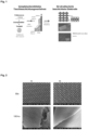
- the SEM image shows a mesoporously templated RuIrTiO x layer calcined at 450 °C on a titanium mesh in top view.
- Fig. 2 is the representation of SEM images of titanium meshes, which can be used preferably as gas diffusion layers.
- the image shows a titanium mesh before (A) and after (B) a coating with mesoporous iridium oxide layers.
- the images arranged above show the meshes at 50x magnification.
- the images arranged below, however, show the meshes at 100,000x magnification.
- the coating was calcined in air at 400 °C.
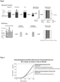
- Fig. 3 shows a schematic flow diagram of a preferred method for producing a catalyst-coated three-dimensionally structured electrode in comparison with a method from the prior art.
- an ink is produced.
- a dispersion comprising preferably isopropanol ( iPrOH ), Nafion, water and a catalyst powder is ultrasonically mixed to an ink.
- a substrate such as a Nafion membrane, is then coated with the ink. The substrate is preferably coated by spraying.
- the membrane is introduced into the full-cell scale.
- the method according to the invention preferably uses dip coating.
- a suspension is generated which comprises, for example, ethanol, a micelle-forming template and a noble metal salt, namely Ir(OAc) 3.
- a three-dimensional substrate is then immersed in a container with the suspension described. Pulling the three-dimensional substrate out of the suspension leads to a layer of a catalyst precursor on the substrate.
- a catalyst layer is then formed using thermal treatment and in a final process step the three-dimensional substrate is introduced into a full-cell scale.
- Fig. 4 shows the electrocatalytic activity of a CCG (catalyst coated gas diffusion layer) coated with mesoporous iridium oxide as an anode in contact with a membrane.
- the membrane is coated on the cathode side with a common Pt/C catalyst (CCM coated on one side).
- CCM catalyst-coated membrane
- CCM coated on both sides a reference system.
- the CCG system achieves a geometric current density that is about twice as high as that of the binder-containing commercial reference.
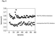
- the in Fig. 5 The illustrated dot diagram shows an increased catalytic activity of three-dimensionally structured electrodes with mesoporous templated catalyst layers in chlorine production.
- a reference catalyst was used, whereby a three-dimensionally structured electrode was coated using a conventional synthesis process and therefore does not contain a templated mesoporous catalyst layer.
Landscapes
- Chemical & Material Sciences (AREA)
- Engineering & Computer Science (AREA)
- Chemical Kinetics & Catalysis (AREA)
- Electrochemistry (AREA)
- Materials Engineering (AREA)
- Organic Chemistry (AREA)
- Metallurgy (AREA)
- General Chemical & Material Sciences (AREA)
- Physics & Mathematics (AREA)
- Thermal Sciences (AREA)
- Inorganic Chemistry (AREA)
- Manufacturing & Machinery (AREA)
- Mechanical Engineering (AREA)
- Ceramic Engineering (AREA)
- Catalysts (AREA)
- Inert Electrodes (AREA)
- Electrolytic Production Of Non-Metals, Compounds, Apparatuses Therefor (AREA)
- Electrodes For Compound Or Non-Metal Manufacture (AREA)
Claims (13)
- Procédé de fabrication d'une électrode structurée à trois dimensions revêtue de catalyseur
comprenant les étapes suivantes :a) la fourniture d'un substrat métallique structuré à trois dimensions ;b) la préparation d'une suspension comprenant un modèle, un précurseur métallique et un solvant ;c) l'application de la suspension sur le substrat métallique structuré à trois dimensions de manière à former un film de suspension sur le substrat métallique structuré à trois dimensions ;d) le séchage du film de suspension sur le substrat métallique structuré à trois dimensions à une température T1 dans une plage entre 18 °C et 250 °C, de sorte que le solvant contenu dans le film de suspension s'évapore et qu'une couche d'un précurseur de catalyseur avec des structures de modèle intégrées est obtenue ;e) le traitement thermique d'un substrat métallique structuré à trois dimensions comprenant des précurseurs de catalyseur à une seconde température T2 comprise entre 200 °C et 1000 °C et à un temps de calcination t2 dans une plage entre 1 minute et 1440 minutes pour former une couche de catalyseur mésoporeuse. - Procédé selon la revendication 1,
caractérisé en ce que
l'application de la suspension de l'étape (c) intervient au moyen d'un revêtement par immersion. - Procédé selon l'une ou plusieurs des revendications précédentes,
caractérisé en ce que
le substrat métallique structuré à trois dimensions est constitué d'un filet, d'une mousse, d'une grille, d'un tamis, d'un tissu et/ou d'un treillis. - Procédé selon l'une ou plusieurs des revendications précédentes,
caractérisé en ce que
la température T2 est comprise entre 300 °C et 800 °C, et le temps de calcination t2 est compris entre 10 et 120 minutes. - Procédé selon l'une ou plusieurs des revendications précédentes,
caractérisé en ce que
la suspension comprend un ou plusieurs copolymères blocs amphiphiles. - Procédé selon la revendication 5,
caractérisé en ce que
le copolymère bloc amphiphile est choisi dans le groupe constitué :de copolymères blocs AB (oxyde de polyéthylène-bloc-polystyrène (PEO-PS), oxyde de polyéthylène-bloc-polyméthacrylate de méthyle (PEO-PMMA), poly-2-venlypyridine-bloc-polyallyl méthacrylate (P2VP-PAMA), polybutadiène-bloc-oxyde de polyéthylène (PB-PEO), polyisoprène-blocméthacrylate de polydiméthylaminoéthyle (PI-PDMAEMA), polybutadiène-blocméthacrylate de polydiméthylaminoéthyle (PB-PDMAEMA), polyéthylène-bloc-oxyde de polyéthylène (PE-PEO), polyisobutylène-bloc-oxyde de polyéthylène (PIB-PEO) et poly(éthylène-co-butylène)-bloc-oxyde de poly(éthylène) (PEB-PEO), polystyrène-bloc-poly(4-vinylpyridine) (PS-P4VP), polyisoprène-bloc-oxyde de polyéthylène (PI-PEO), polydiméthoxyaniline-bloc-polystyrène (PDMA-PS), oxyde de polyéthylènebloc-acrylate de poly-n-utyle (PEO-PBA), polybutadiène-bloc-poly(2-vinylpyridine (PB-P2VP)), oxyde de polyéthylène-bloc-polylactide (PEO-PLA), oxyde de polyéthylène-bloc-polyglycolide (PEO-PLGA), oxyde de polyéthylène-bloc-polycaprolactone (PEO-PCL), polyéthylène-bloc-polyéthylène glycol (PE-PEO), polystyrène-blocpolyméthacrylate de méthyle (PS-PMMA), polystyrène-bloc-acide polyacrylique (PS-PAA), polypyrrole-bloc-polycaprolactone (PPy-PCL), polysilicium-bloc-oxyde de polyéthylène (PDMS-PEO),de copolymères blocs ABA (oxyde de polyéthylène-bloc-polybutadiène-bloc-oxyde de polyéthylène (PEO-PB-PEO), oxyde de polyéthylène-bloc-oxyde de polypropylène-bloc-oxyde de polyéthylène (PEO-PPO-PEO), oxyde de polypropylène-bloc-oxyde de polyéthylène-bloc-oxyde de polypropylène (PPO-PEO-PPO), oxyde de polyéthylène-bloc-polyisobutylène-bloc-oxyde de polyéthylène (PEO-PIB-PEO), oxyde de polyéthylène-bloc-polybutadiène-bloc-oxyde de polyéthylène (PEO-PB-PEO)), polylactide-bloc-oxyde de polyéthylène-bloc-polylactide (PLA-PEO-PLA),polyglycolide-bloc-oxyde de polyéthylène-bloc-polyglycolide (PGLA-PEO-PGLA), polylactide-co-caprolactone-bloc-oxyde de polyéthylène-bloc-polylactide-co-caprolactone (PLCL-PEO-PLCL), polycaprolactone-bloc-polytétrahydrofurane-bloc-polycaprolactone (PCL-PTHF-PCL), oxyde de polypropylène-bloc-oxyde de polyéthylène-bloc-oxyde de polypropylène (PPG-PEO-PPG), polystyrène-bloc-polybutadiène-bloc-polystyrène (PS-PB-PS), polystyrène-ran-butylène-bloc-polystyrène (PS-PEB-PS), polystyrène-bloc-polyisoprène-bloc-polystyrène (PS-PI-PS),de copolymères blocs ABC (polyisoprène-bloc-polystyrène-bloc-oxyde de polyéthylène (PI-PS-PEO), polystyrène-bloc-polyvinylpyrrolidone-bloc-oxyde de polyéthylène (PS-PVP-PEO), polystyrène-bloc-poly-2-vénylpyridine-bloc-oxyde de polyéthylène (PS-P2VP-PEO), polystyrène-bloc-poly-2-vénylpyridine-bloc-oxyde de polyéthylène (PS-P2VP-PEO), polystyrène-bloc-acide polyacrylique-oxyde de polyéthylène (PS-PAA-PEO)), oxyde de polyéthylène-bloc-polylactide-bloc-décane (PEO-PLA-décane),ainsi que d'autres polymères amphiphiles (oxyde de polyéthylène-éther alkylique (PEO-Cxx), par exemple Brij35, Brij56, Brij58) ou des mélanges de ceux-ci,de préférence PEO-PB, PEO-PPO, PEO-PB-PEO, PEO-PPO-PEO. - Procédé selon l'une ou plusieurs des revendications précédentes,
caractérisé en ce que
un sel métallique ou plusieurs sels métalliques de différents métaux, ou leurs hydrates, sont utilisés comme précurseur métallique. - Procédé selon la revendication 7,
caractérisé en ce que
les sels métalliques sont choisis dans le groupe constitué du nitrate métallique, de l'halogénure métallique, du sulfate métallique, de l'acétate métallique, du citrate métallique, de l'alcoxyde métallique ou de mélanges de ceux-ci. - Procédé selon l'une ou plusieurs des revendications précédentes,
caractérisé en ce que
les métaux contenus dans le précurseur métallique sont choisis dans le groupe constitué de métaux alcalins, de préférence le lithium, le sodium, le potassium, le rubidium, le césium, de métaux alcalino-terreux, de préférence le magnésium, le calcium, le strontium, le baryum, de métaux du troisième groupe principal du tableau périodique, de préférence le bore, l'aluminium, l'indium, le gallium, le thallium, de métaux du quatrième groupe principal du tableau périodique, de préférence l'étain, le silicium, le germanium, le plomb, de métaux du cinquième groupe principal du tableau périodique, de préférence le bismuth, et de métaux de transition, de préférence l'iridium, le ruthénium, le cobalt, le zinc, le cuivre, le manganèse, le cadmium, le vanadium, l'yttrium, le zirconium, le scandium, le titane. - Procédé selon l'une ou plusieurs des revendications précédentes,
caractérisé en ce que
le solvant utilisé est l'eau ou un alcool en C1-C4, un ester en C2-C4, un éther en C2-C4, le formamide, l'acétonitrile, l'acétone, le tétrahydrofurane, le benzyle, le toluène, le diméthylsulfoxyde, le dichlorométhane, le chloroforme ou des mélanges de ceux-ci, de préférence le méthanol, l'éthanol, le formamide et/ou le tétrahydrofurane. - Électrode pour une cellule électrochimique fabriquée par un procédé selon l'une ou plusieurs des revendications précédentes, caractérisée en ce que
l'électrode est un substrat métallique structuré à trois dimensions et comprend une couche de catalyseur mésoporeuse nanostructurée. - Électrode selon la revendication 11
caractérisée en ce que
le substrat métallique structuré à trois dimensions est constitué d'un filet, d'une mousse, d'une grille, d'un tissu et/ou d'un treillis. - Cellule électrochimique comprenant une électrode selon les revendications 11 et/ou 12.
Applications Claiming Priority (2)
| Application Number | Priority Date | Filing Date | Title |
|---|---|---|---|
| EP21151795.8A EP4030511A1 (fr) | 2021-01-15 | 2021-01-15 | Procédé de fabrication d'une électrode structurée à trois dimensions revêtue de catalyseur |
| PCT/EP2022/050728 WO2022152836A1 (fr) | 2021-01-15 | 2022-01-14 | Procédé de production d'une électrode structurée en trois dimensions revêtue de catalyseur |
Publications (3)
| Publication Number | Publication Date |
|---|---|
| EP4278397A1 EP4278397A1 (fr) | 2023-11-22 |
| EP4278397B1 true EP4278397B1 (fr) | 2025-01-01 |
| EP4278397C0 EP4278397C0 (fr) | 2025-01-01 |
Family
ID=74186471
Family Applications (2)
| Application Number | Title | Priority Date | Filing Date |
|---|---|---|---|
| EP21151795.8A Withdrawn EP4030511A1 (fr) | 2021-01-15 | 2021-01-15 | Procédé de fabrication d'une électrode structurée à trois dimensions revêtue de catalyseur |
| EP22701345.5A Active EP4278397B1 (fr) | 2021-01-15 | 2022-01-14 | Procédé de fabrication d'une électrode structurée à trois dimensions revêtue de catalyseur |
Family Applications Before (1)
| Application Number | Title | Priority Date | Filing Date |
|---|---|---|---|
| EP21151795.8A Withdrawn EP4030511A1 (fr) | 2021-01-15 | 2021-01-15 | Procédé de fabrication d'une électrode structurée à trois dimensions revêtue de catalyseur |
Country Status (7)
| Country | Link |
|---|---|
| US (1) | US20240141500A1 (fr) |
| EP (2) | EP4030511A1 (fr) |
| JP (1) | JP2024505405A (fr) |
| CN (1) | CN116711106A (fr) |
| AU (1) | AU2022207651A1 (fr) |
| CA (1) | CA3204653A1 (fr) |
| WO (1) | WO2022152836A1 (fr) |
Family Cites Families (8)
| Publication number | Priority date | Publication date | Assignee | Title |
|---|---|---|---|---|
| DE19544323A1 (de) | 1995-11-28 | 1997-06-05 | Magnet Motor Gmbh | Gasdiffusionselektrode für Polymerelektrolytmembran-Brennstoffzellen |
| WO2011003884A1 (fr) | 2009-07-07 | 2011-01-13 | Basf Se | Encre renfermant des particules de polymère, électrode et unité mea correspondantes |
| JP6312981B2 (ja) * | 2012-10-05 | 2018-04-18 | 国立大学法人 新潟大学 | メソポーラス酸化イリジウムの製造方法、水の酸化触媒の製造方法、及びメソポーラス酸化イリジウム電極の製造方法 |
| JP6162010B2 (ja) * | 2013-09-19 | 2017-07-12 | 国立大学法人 新潟大学 | メソポーラス酸化タングステンの製造方法、光触媒の製造方法、及びメソポーラス酸化タングステン電極の製造方法 |
| JP6990236B2 (ja) * | 2017-04-24 | 2022-01-12 | 住友電気工業株式会社 | 酸化物分散金属多孔体、電解用電極および水素製造装置 |
| KR101950465B1 (ko) * | 2017-08-11 | 2019-05-02 | 주식회사 엘지화학 | 전해용 전극 및 이의 제조방법 |
| KR102347983B1 (ko) * | 2018-07-06 | 2022-01-07 | 주식회사 엘지화학 | 전기분해용 환원전극 및 이의 제조방법 |
| CN110783574A (zh) * | 2019-11-05 | 2020-02-11 | 江苏大学 | 一种直接醇类燃料电池气体扩散电极及其制备方法和直接醇类燃料电池 |
-
2021
- 2021-01-15 EP EP21151795.8A patent/EP4030511A1/fr not_active Withdrawn
-
2022
- 2022-01-14 CN CN202280010448.4A patent/CN116711106A/zh active Pending
- 2022-01-14 AU AU2022207651A patent/AU2022207651A1/en active Pending
- 2022-01-14 JP JP2023541967A patent/JP2024505405A/ja active Pending
- 2022-01-14 EP EP22701345.5A patent/EP4278397B1/fr active Active
- 2022-01-14 WO PCT/EP2022/050728 patent/WO2022152836A1/fr not_active Ceased
- 2022-01-14 CA CA3204653A patent/CA3204653A1/fr active Pending
- 2022-01-14 US US18/272,234 patent/US20240141500A1/en active Pending
Also Published As
| Publication number | Publication date |
|---|---|
| AU2022207651A1 (en) | 2023-07-13 |
| CN116711106A (zh) | 2023-09-05 |
| US20240141500A1 (en) | 2024-05-02 |
| JP2024505405A (ja) | 2024-02-06 |
| AU2022207651A9 (en) | 2024-02-08 |
| EP4278397A1 (fr) | 2023-11-22 |
| WO2022152836A1 (fr) | 2022-07-21 |
| EP4030511A1 (fr) | 2022-07-20 |
| EP4278397C0 (fr) | 2025-01-01 |
| CA3204653A1 (fr) | 2022-07-21 |
Similar Documents
| Publication | Publication Date | Title |
|---|---|---|
| EP1728896B1 (fr) | Procede pour produire des électrodes a diffusion gazeuse | |
| EP2954951B1 (fr) | Catalyseur sur support et procédé de fabrication d'un matériau de carbone graphité poreux, revêtu de nanoparticules métalliques | |
| DE2720529C2 (de) | Verfahren zur Herstellung einer Brennstoffzellenelektrode | |
| EP2050155B1 (fr) | Électrode pour une pile à combustible à carbonate fondu et son procédé de fabrication | |
| EP0297315B1 (fr) | Procédé pour la préparation d'un article fait d'une couche de cermet et d'une couche de métal poreux sur une ou deux faces de la couche de cermet comme diaphragme avec électrodes | |
| DE102016218230A1 (de) | Selektive elektrochemische Hydrierung von Alkinen zu Alkenen | |
| DE102007033753B4 (de) | An seiner Oberfläche mit metallischen Nanopartikeln versehenes ultrahydrophobes Substrat, Verfahren zu dessen Herstellung und Verwendung desselben | |
| DE102018132399A1 (de) | Gasdiffusionskörper | |
| EP3513416A1 (fr) | Procédé de fabrication de composants électroniques par impression 3d | |
| DE10148072A1 (de) | Keramikkatalysatorkörper, Keramikträger und ihre Herstellungsverfahren | |
| EP2771895A2 (fr) | Anodes résistant à la déformation imprimées au pochoir sur une tôle ta/nb | |
| EP4222797B1 (fr) | Procédé de fabrication de membranes revêtues d'un catalyseur | |
| EP4278397B1 (fr) | Procédé de fabrication d'une électrode structurée à trois dimensions revêtue de catalyseur | |
| DE10118651A1 (de) | Brennstoffzelle | |
| DE102010053782B4 (de) | Segmentierte Nanodrähte mit polykristalliner Struktur und Verfahren zu deren Herstellung | |
| DE102023115632A1 (de) | Elektroden für eine elektrochemische Zelle zur alkalischen Aufspaltung von Wasser in Wasserstoff und Sauerstoff sowie Verfahren zu deren Herstellung | |
| EP4198175A2 (fr) | Électrolyte supporté, son procédé de fabrication et son utilisation | |
| DE102023209672B3 (de) | Elektrode für elektrochemische Zellen | |
| EP1951641B1 (fr) | Procédé de fabrication d'un mince film céramique poreux | |
| HK40103055B (en) | Method of manufacturing a catalyst-coated three-dimensionally structured electrode | |
| HK40103055A (en) | Method of manufacturing a catalyst-coated three-dimensionally structured electrode | |
| DE102023134698A1 (de) | Verfahren zum Herstellen einer Elektrode für die Verwendung bei der alkalischen Elektrolyse von Wasser sowie Elektrode | |
| DE102010003294B4 (de) | Elektrode aus einem elektrisch leitenden Verbundwerkstoff und Verfahren zur Herstellung | |
| DE2510078C3 (de) | Gasdiffusionselektrode für elektrochemische Zellen | |
| DE102010042730A1 (de) | Sauerstoffverzehrelektrode |
Legal Events
| Date | Code | Title | Description |
|---|---|---|---|
| STAA | Information on the status of an ep patent application or granted ep patent |
Free format text: STATUS: UNKNOWN |
|
| STAA | Information on the status of an ep patent application or granted ep patent |
Free format text: STATUS: THE INTERNATIONAL PUBLICATION HAS BEEN MADE |
|
| PUAI | Public reference made under article 153(3) epc to a published international application that has entered the european phase |
Free format text: ORIGINAL CODE: 0009012 |
|
| STAA | Information on the status of an ep patent application or granted ep patent |
Free format text: STATUS: REQUEST FOR EXAMINATION WAS MADE |
|
| 17P | Request for examination filed |
Effective date: 20230810 |
|
| AK | Designated contracting states |
Kind code of ref document: A1 Designated state(s): AL AT BE BG CH CY CZ DE DK EE ES FI FR GB GR HR HU IE IS IT LI LT LU LV MC MK MT NL NO PL PT RO RS SE SI SK SM TR |
|
| DAV | Request for validation of the european patent (deleted) | ||
| DAX | Request for extension of the european patent (deleted) | ||
| REG | Reference to a national code |
Ref country code: DE Ref legal event code: R079 Free format text: PREVIOUS MAIN CLASS: H01M0004860000 Ref country code: DE Ref legal event code: R079 Ref document number: 502022002579 Country of ref document: DE Free format text: PREVIOUS MAIN CLASS: H01M0004860000 Ipc: C23C0018120000 |
|
| RIC1 | Information provided on ipc code assigned before grant |
Ipc: C25B 1/04 20210101ALI20240612BHEP Ipc: C25B 11/063 20210101ALI20240612BHEP Ipc: H01M 8/10 20160101ALI20240612BHEP Ipc: H01M 4/88 20060101ALI20240612BHEP Ipc: H01M 4/86 20060101ALI20240612BHEP Ipc: C25B 11/081 20210101ALI20240612BHEP Ipc: C25B 11/056 20210101ALI20240612BHEP Ipc: C25B 11/032 20210101ALI20240612BHEP Ipc: C25B 11/052 20210101ALI20240612BHEP Ipc: C25B 9/23 20210101ALI20240612BHEP Ipc: C25B 1/46 20060101ALI20240612BHEP Ipc: C23C 18/12 20060101AFI20240612BHEP |
|
| GRAP | Despatch of communication of intention to grant a patent |
Free format text: ORIGINAL CODE: EPIDOSNIGR1 |
|
| STAA | Information on the status of an ep patent application or granted ep patent |
Free format text: STATUS: GRANT OF PATENT IS INTENDED |
|
| INTG | Intention to grant announced |
Effective date: 20240725 |
|
| GRAS | Grant fee paid |
Free format text: ORIGINAL CODE: EPIDOSNIGR3 |
|
| GRAA | (expected) grant |
Free format text: ORIGINAL CODE: 0009210 |
|
| STAA | Information on the status of an ep patent application or granted ep patent |
Free format text: STATUS: THE PATENT HAS BEEN GRANTED |
|
| AK | Designated contracting states |
Kind code of ref document: B1 Designated state(s): AL AT BE BG CH CY CZ DE DK EE ES FI FR GB GR HR HU IE IS IT LI LT LU LV MC MK MT NL NO PL PT RO RS SE SI SK SM TR |
|
| REG | Reference to a national code |
Ref country code: GB Ref legal event code: FG4D Free format text: NOT ENGLISH |
|
| REG | Reference to a national code |
Ref country code: CH Ref legal event code: EP |
|
| REG | Reference to a national code |
Ref country code: DE Ref legal event code: R096 Ref document number: 502022002579 Country of ref document: DE |
|
| REG | Reference to a national code |
Ref country code: IE Ref legal event code: FG4D Free format text: LANGUAGE OF EP DOCUMENT: GERMAN |
|
| U01 | Request for unitary effect filed |
Effective date: 20250123 |
|
| U07 | Unitary effect registered |
Designated state(s): AT BE BG DE DK EE FI FR IT LT LU LV MT NL PT RO SE SI Effective date: 20250129 |
|
| U20 | Renewal fee for the european patent with unitary effect paid |
Year of fee payment: 4 Effective date: 20250130 |
|
| PG25 | Lapsed in a contracting state [announced via postgrant information from national office to epo] |
Ref country code: PL Free format text: LAPSE BECAUSE OF FAILURE TO SUBMIT A TRANSLATION OF THE DESCRIPTION OR TO PAY THE FEE WITHIN THE PRESCRIBED TIME-LIMIT Effective date: 20250101 |
|
| PG25 | Lapsed in a contracting state [announced via postgrant information from national office to epo] |
Ref country code: ES Free format text: LAPSE BECAUSE OF FAILURE TO SUBMIT A TRANSLATION OF THE DESCRIPTION OR TO PAY THE FEE WITHIN THE PRESCRIBED TIME-LIMIT Effective date: 20250101 |
|
| PG25 | Lapsed in a contracting state [announced via postgrant information from national office to epo] |
Ref country code: IS Free format text: LAPSE BECAUSE OF FAILURE TO SUBMIT A TRANSLATION OF THE DESCRIPTION OR TO PAY THE FEE WITHIN THE PRESCRIBED TIME-LIMIT Effective date: 20250501 Ref country code: NO Free format text: LAPSE BECAUSE OF FAILURE TO SUBMIT A TRANSLATION OF THE DESCRIPTION OR TO PAY THE FEE WITHIN THE PRESCRIBED TIME-LIMIT Effective date: 20250401 |
|
| PG25 | Lapsed in a contracting state [announced via postgrant information from national office to epo] |
Ref country code: HR Free format text: LAPSE BECAUSE OF FAILURE TO SUBMIT A TRANSLATION OF THE DESCRIPTION OR TO PAY THE FEE WITHIN THE PRESCRIBED TIME-LIMIT Effective date: 20250101 |
|
| PG25 | Lapsed in a contracting state [announced via postgrant information from national office to epo] |
Ref country code: GR Free format text: LAPSE BECAUSE OF FAILURE TO SUBMIT A TRANSLATION OF THE DESCRIPTION OR TO PAY THE FEE WITHIN THE PRESCRIBED TIME-LIMIT Effective date: 20250402 |
|
| PG25 | Lapsed in a contracting state [announced via postgrant information from national office to epo] |
Ref country code: CZ Free format text: LAPSE BECAUSE OF FAILURE TO SUBMIT A TRANSLATION OF THE DESCRIPTION OR TO PAY THE FEE WITHIN THE PRESCRIBED TIME-LIMIT Effective date: 20250101 |
|
| REG | Reference to a national code |
Ref country code: CH Ref legal event code: PL |
|
| PG25 | Lapsed in a contracting state [announced via postgrant information from national office to epo] |
Ref country code: SM Free format text: LAPSE BECAUSE OF FAILURE TO SUBMIT A TRANSLATION OF THE DESCRIPTION OR TO PAY THE FEE WITHIN THE PRESCRIBED TIME-LIMIT Effective date: 20250101 |
|
| PG25 | Lapsed in a contracting state [announced via postgrant information from national office to epo] |
Ref country code: MC Free format text: LAPSE BECAUSE OF FAILURE TO SUBMIT A TRANSLATION OF THE DESCRIPTION OR TO PAY THE FEE WITHIN THE PRESCRIBED TIME-LIMIT Effective date: 20250101 |
|
| PG25 | Lapsed in a contracting state [announced via postgrant information from national office to epo] |
Ref country code: CH Free format text: LAPSE BECAUSE OF NON-PAYMENT OF DUE FEES Effective date: 20250131 |
|
| PG25 | Lapsed in a contracting state [announced via postgrant information from national office to epo] |
Ref country code: SK Free format text: LAPSE BECAUSE OF FAILURE TO SUBMIT A TRANSLATION OF THE DESCRIPTION OR TO PAY THE FEE WITHIN THE PRESCRIBED TIME-LIMIT Effective date: 20250101 |
|
| PLBE | No opposition filed within time limit |
Free format text: ORIGINAL CODE: 0009261 |
|
| STAA | Information on the status of an ep patent application or granted ep patent |
Free format text: STATUS: NO OPPOSITION FILED WITHIN TIME LIMIT |