EP4278397B1 - Method of manufacturing a catalyst-coated three-dimensionally structured electrode - Google Patents
Method of manufacturing a catalyst-coated three-dimensionally structured electrode Download PDFInfo
- Publication number
- EP4278397B1 EP4278397B1 EP22701345.5A EP22701345A EP4278397B1 EP 4278397 B1 EP4278397 B1 EP 4278397B1 EP 22701345 A EP22701345 A EP 22701345A EP 4278397 B1 EP4278397 B1 EP 4278397B1
- Authority
- EP
- European Patent Office
- Prior art keywords
- block
- peo
- poly
- polyethylene oxide
- polystyrene
- Prior art date
- Legal status (The legal status is an assumption and is not a legal conclusion. Google has not performed a legal analysis and makes no representation as to the accuracy of the status listed.)
- Active
Links
Images
Classifications
-
- C—CHEMISTRY; METALLURGY
- C23—COATING METALLIC MATERIAL; COATING MATERIAL WITH METALLIC MATERIAL; CHEMICAL SURFACE TREATMENT; DIFFUSION TREATMENT OF METALLIC MATERIAL; COATING BY VACUUM EVAPORATION, BY SPUTTERING, BY ION IMPLANTATION OR BY CHEMICAL VAPOUR DEPOSITION, IN GENERAL; INHIBITING CORROSION OF METALLIC MATERIAL OR INCRUSTATION IN GENERAL
- C23C—COATING METALLIC MATERIAL; COATING MATERIAL WITH METALLIC MATERIAL; SURFACE TREATMENT OF METALLIC MATERIAL BY DIFFUSION INTO THE SURFACE, BY CHEMICAL CONVERSION OR SUBSTITUTION; COATING BY VACUUM EVAPORATION, BY SPUTTERING, BY ION IMPLANTATION OR BY CHEMICAL VAPOUR DEPOSITION, IN GENERAL
- C23C18/00—Chemical coating by decomposition of either liquid compounds or solutions of the coating forming compounds, without leaving reaction products of surface material in the coating; Contact plating
- C23C18/02—Chemical coating by decomposition of either liquid compounds or solutions of the coating forming compounds, without leaving reaction products of surface material in the coating; Contact plating by thermal decomposition
- C23C18/12—Chemical coating by decomposition of either liquid compounds or solutions of the coating forming compounds, without leaving reaction products of surface material in the coating; Contact plating by thermal decomposition characterised by the deposition of inorganic material other than metallic material
- C23C18/125—Process of deposition of the inorganic material
- C23C18/1295—Process of deposition of the inorganic material with after-treatment of the deposited inorganic material
-
- H—ELECTRICITY
- H01—ELECTRIC ELEMENTS
- H01M—PROCESSES OR MEANS, e.g. BATTERIES, FOR THE DIRECT CONVERSION OF CHEMICAL ENERGY INTO ELECTRICAL ENERGY
- H01M4/00—Electrodes
- H01M4/86—Inert electrodes with catalytic activity, e.g. for fuel cells
- H01M4/88—Processes of manufacture
- H01M4/8803—Supports for the deposition of the catalytic active composition
-
- C—CHEMISTRY; METALLURGY
- C23—COATING METALLIC MATERIAL; COATING MATERIAL WITH METALLIC MATERIAL; CHEMICAL SURFACE TREATMENT; DIFFUSION TREATMENT OF METALLIC MATERIAL; COATING BY VACUUM EVAPORATION, BY SPUTTERING, BY ION IMPLANTATION OR BY CHEMICAL VAPOUR DEPOSITION, IN GENERAL; INHIBITING CORROSION OF METALLIC MATERIAL OR INCRUSTATION IN GENERAL
- C23C—COATING METALLIC MATERIAL; COATING MATERIAL WITH METALLIC MATERIAL; SURFACE TREATMENT OF METALLIC MATERIAL BY DIFFUSION INTO THE SURFACE, BY CHEMICAL CONVERSION OR SUBSTITUTION; COATING BY VACUUM EVAPORATION, BY SPUTTERING, BY ION IMPLANTATION OR BY CHEMICAL VAPOUR DEPOSITION, IN GENERAL
- C23C18/00—Chemical coating by decomposition of either liquid compounds or solutions of the coating forming compounds, without leaving reaction products of surface material in the coating; Contact plating
- C23C18/02—Chemical coating by decomposition of either liquid compounds or solutions of the coating forming compounds, without leaving reaction products of surface material in the coating; Contact plating by thermal decomposition
- C23C18/12—Chemical coating by decomposition of either liquid compounds or solutions of the coating forming compounds, without leaving reaction products of surface material in the coating; Contact plating by thermal decomposition characterised by the deposition of inorganic material other than metallic material
- C23C18/1204—Chemical coating by decomposition of either liquid compounds or solutions of the coating forming compounds, without leaving reaction products of surface material in the coating; Contact plating by thermal decomposition characterised by the deposition of inorganic material other than metallic material inorganic material, e.g. non-oxide and non-metallic such as sulfides, nitrides based compounds
- C23C18/1208—Oxides, e.g. ceramics
- C23C18/1216—Metal oxides
-
- C—CHEMISTRY; METALLURGY
- C23—COATING METALLIC MATERIAL; COATING MATERIAL WITH METALLIC MATERIAL; CHEMICAL SURFACE TREATMENT; DIFFUSION TREATMENT OF METALLIC MATERIAL; COATING BY VACUUM EVAPORATION, BY SPUTTERING, BY ION IMPLANTATION OR BY CHEMICAL VAPOUR DEPOSITION, IN GENERAL; INHIBITING CORROSION OF METALLIC MATERIAL OR INCRUSTATION IN GENERAL
- C23C—COATING METALLIC MATERIAL; COATING MATERIAL WITH METALLIC MATERIAL; SURFACE TREATMENT OF METALLIC MATERIAL BY DIFFUSION INTO THE SURFACE, BY CHEMICAL CONVERSION OR SUBSTITUTION; COATING BY VACUUM EVAPORATION, BY SPUTTERING, BY ION IMPLANTATION OR BY CHEMICAL VAPOUR DEPOSITION, IN GENERAL
- C23C18/00—Chemical coating by decomposition of either liquid compounds or solutions of the coating forming compounds, without leaving reaction products of surface material in the coating; Contact plating
- C23C18/02—Chemical coating by decomposition of either liquid compounds or solutions of the coating forming compounds, without leaving reaction products of surface material in the coating; Contact plating by thermal decomposition
- C23C18/12—Chemical coating by decomposition of either liquid compounds or solutions of the coating forming compounds, without leaving reaction products of surface material in the coating; Contact plating by thermal decomposition characterised by the deposition of inorganic material other than metallic material
- C23C18/1229—Composition of the substrate
- C23C18/1241—Metallic substrates
-
- C—CHEMISTRY; METALLURGY
- C25—ELECTROLYTIC OR ELECTROPHORETIC PROCESSES; APPARATUS THEREFOR
- C25B—ELECTROLYTIC OR ELECTROPHORETIC PROCESSES FOR THE PRODUCTION OF COMPOUNDS OR NON-METALS; APPARATUS THEREFOR
- C25B1/00—Electrolytic production of inorganic compounds or non-metals
- C25B1/01—Products
- C25B1/02—Hydrogen or oxygen
- C25B1/04—Hydrogen or oxygen by electrolysis of water
-
- C—CHEMISTRY; METALLURGY
- C25—ELECTROLYTIC OR ELECTROPHORETIC PROCESSES; APPARATUS THEREFOR
- C25B—ELECTROLYTIC OR ELECTROPHORETIC PROCESSES FOR THE PRODUCTION OF COMPOUNDS OR NON-METALS; APPARATUS THEREFOR
- C25B1/00—Electrolytic production of inorganic compounds or non-metals
- C25B1/01—Products
- C25B1/34—Simultaneous production of alkali metal hydroxides and chlorine, oxyacids or salts of chlorine, e.g. by chlor-alkali electrolysis
- C25B1/46—Simultaneous production of alkali metal hydroxides and chlorine, oxyacids or salts of chlorine, e.g. by chlor-alkali electrolysis in diaphragm cells
-
- C—CHEMISTRY; METALLURGY
- C25—ELECTROLYTIC OR ELECTROPHORETIC PROCESSES; APPARATUS THEREFOR
- C25B—ELECTROLYTIC OR ELECTROPHORETIC PROCESSES FOR THE PRODUCTION OF COMPOUNDS OR NON-METALS; APPARATUS THEREFOR
- C25B11/00—Electrodes; Manufacture thereof not otherwise provided for
- C25B11/02—Electrodes; Manufacture thereof not otherwise provided for characterised by shape or form
- C25B11/03—Electrodes; Manufacture thereof not otherwise provided for characterised by shape or form perforated or foraminous
- C25B11/031—Porous electrodes
- C25B11/032—Gas diffusion electrodes
-
- C—CHEMISTRY; METALLURGY
- C25—ELECTROLYTIC OR ELECTROPHORETIC PROCESSES; APPARATUS THEREFOR
- C25B—ELECTROLYTIC OR ELECTROPHORETIC PROCESSES FOR THE PRODUCTION OF COMPOUNDS OR NON-METALS; APPARATUS THEREFOR
- C25B11/00—Electrodes; Manufacture thereof not otherwise provided for
- C25B11/04—Electrodes; Manufacture thereof not otherwise provided for characterised by the material
- C25B11/051—Electrodes formed of electrocatalysts on a substrate or carrier
- C25B11/052—Electrodes comprising one or more electrocatalytic coatings on a substrate
-
- C—CHEMISTRY; METALLURGY
- C25—ELECTROLYTIC OR ELECTROPHORETIC PROCESSES; APPARATUS THEREFOR
- C25B—ELECTROLYTIC OR ELECTROPHORETIC PROCESSES FOR THE PRODUCTION OF COMPOUNDS OR NON-METALS; APPARATUS THEREFOR
- C25B11/00—Electrodes; Manufacture thereof not otherwise provided for
- C25B11/04—Electrodes; Manufacture thereof not otherwise provided for characterised by the material
- C25B11/051—Electrodes formed of electrocatalysts on a substrate or carrier
- C25B11/055—Electrodes formed of electrocatalysts on a substrate or carrier characterised by the substrate or carrier material
- C25B11/056—Electrodes formed of electrocatalysts on a substrate or carrier characterised by the substrate or carrier material consisting of textile or non-woven fabric
-
- C—CHEMISTRY; METALLURGY
- C25—ELECTROLYTIC OR ELECTROPHORETIC PROCESSES; APPARATUS THEREFOR
- C25B—ELECTROLYTIC OR ELECTROPHORETIC PROCESSES FOR THE PRODUCTION OF COMPOUNDS OR NON-METALS; APPARATUS THEREFOR
- C25B11/00—Electrodes; Manufacture thereof not otherwise provided for
- C25B11/04—Electrodes; Manufacture thereof not otherwise provided for characterised by the material
- C25B11/051—Electrodes formed of electrocatalysts on a substrate or carrier
- C25B11/055—Electrodes formed of electrocatalysts on a substrate or carrier characterised by the substrate or carrier material
- C25B11/057—Electrodes formed of electrocatalysts on a substrate or carrier characterised by the substrate or carrier material consisting of a single element or compound
- C25B11/061—Metal or alloy
- C25B11/063—Valve metal, e.g. titanium
-
- C—CHEMISTRY; METALLURGY
- C25—ELECTROLYTIC OR ELECTROPHORETIC PROCESSES; APPARATUS THEREFOR
- C25B—ELECTROLYTIC OR ELECTROPHORETIC PROCESSES FOR THE PRODUCTION OF COMPOUNDS OR NON-METALS; APPARATUS THEREFOR
- C25B11/00—Electrodes; Manufacture thereof not otherwise provided for
- C25B11/04—Electrodes; Manufacture thereof not otherwise provided for characterised by the material
- C25B11/051—Electrodes formed of electrocatalysts on a substrate or carrier
- C25B11/073—Electrodes formed of electrocatalysts on a substrate or carrier characterised by the electrocatalyst material
- C25B11/075—Electrodes formed of electrocatalysts on a substrate or carrier characterised by the electrocatalyst material consisting of a single catalytic element or catalytic compound
- C25B11/077—Electrodes formed of electrocatalysts on a substrate or carrier characterised by the electrocatalyst material consisting of a single catalytic element or catalytic compound the compound being a non-noble metal oxide
-
- C—CHEMISTRY; METALLURGY
- C25—ELECTROLYTIC OR ELECTROPHORETIC PROCESSES; APPARATUS THEREFOR
- C25B—ELECTROLYTIC OR ELECTROPHORETIC PROCESSES FOR THE PRODUCTION OF COMPOUNDS OR NON-METALS; APPARATUS THEREFOR
- C25B11/00—Electrodes; Manufacture thereof not otherwise provided for
- C25B11/04—Electrodes; Manufacture thereof not otherwise provided for characterised by the material
- C25B11/051—Electrodes formed of electrocatalysts on a substrate or carrier
- C25B11/073—Electrodes formed of electrocatalysts on a substrate or carrier characterised by the electrocatalyst material
- C25B11/075—Electrodes formed of electrocatalysts on a substrate or carrier characterised by the electrocatalyst material consisting of a single catalytic element or catalytic compound
- C25B11/081—Electrodes formed of electrocatalysts on a substrate or carrier characterised by the electrocatalyst material consisting of a single catalytic element or catalytic compound the element being a noble metal
-
- C—CHEMISTRY; METALLURGY
- C25—ELECTROLYTIC OR ELECTROPHORETIC PROCESSES; APPARATUS THEREFOR
- C25B—ELECTROLYTIC OR ELECTROPHORETIC PROCESSES FOR THE PRODUCTION OF COMPOUNDS OR NON-METALS; APPARATUS THEREFOR
- C25B9/00—Cells or assemblies of cells; Constructional parts of cells; Assemblies of constructional parts, e.g. electrode-diaphragm assemblies; Process-related cell features
- C25B9/17—Cells comprising dimensionally-stable non-movable electrodes; Assemblies of constructional parts thereof
- C25B9/19—Cells comprising dimensionally-stable non-movable electrodes; Assemblies of constructional parts thereof with diaphragms
- C25B9/23—Cells comprising dimensionally-stable non-movable electrodes; Assemblies of constructional parts thereof with diaphragms comprising ion-exchange membranes in or on which electrode material is embedded
-
- H—ELECTRICITY
- H01—ELECTRIC ELEMENTS
- H01M—PROCESSES OR MEANS, e.g. BATTERIES, FOR THE DIRECT CONVERSION OF CHEMICAL ENERGY INTO ELECTRICAL ENERGY
- H01M4/00—Electrodes
- H01M4/86—Inert electrodes with catalytic activity, e.g. for fuel cells
- H01M4/8605—Porous electrodes
-
- H—ELECTRICITY
- H01—ELECTRIC ELEMENTS
- H01M—PROCESSES OR MEANS, e.g. BATTERIES, FOR THE DIRECT CONVERSION OF CHEMICAL ENERGY INTO ELECTRICAL ENERGY
- H01M4/00—Electrodes
- H01M4/86—Inert electrodes with catalytic activity, e.g. for fuel cells
- H01M4/8663—Selection of inactive substances as ingredients for catalytic active masses, e.g. binders, fillers
-
- H—ELECTRICITY
- H01—ELECTRIC ELEMENTS
- H01M—PROCESSES OR MEANS, e.g. BATTERIES, FOR THE DIRECT CONVERSION OF CHEMICAL ENERGY INTO ELECTRICAL ENERGY
- H01M4/00—Electrodes
- H01M4/86—Inert electrodes with catalytic activity, e.g. for fuel cells
- H01M4/88—Processes of manufacture
- H01M4/8803—Supports for the deposition of the catalytic active composition
- H01M4/8807—Gas diffusion layers
-
- H—ELECTRICITY
- H01—ELECTRIC ELEMENTS
- H01M—PROCESSES OR MEANS, e.g. BATTERIES, FOR THE DIRECT CONVERSION OF CHEMICAL ENERGY INTO ELECTRICAL ENERGY
- H01M4/00—Electrodes
- H01M4/86—Inert electrodes with catalytic activity, e.g. for fuel cells
- H01M4/88—Processes of manufacture
- H01M4/8825—Methods for deposition of the catalytic active composition
- H01M4/8842—Coating using a catalyst salt precursor in solution followed by evaporation and reduction of the precursor
-
- H—ELECTRICITY
- H01—ELECTRIC ELEMENTS
- H01M—PROCESSES OR MEANS, e.g. BATTERIES, FOR THE DIRECT CONVERSION OF CHEMICAL ENERGY INTO ELECTRICAL ENERGY
- H01M4/00—Electrodes
- H01M4/86—Inert electrodes with catalytic activity, e.g. for fuel cells
- H01M4/88—Processes of manufacture
- H01M4/8878—Treatment steps after deposition of the catalytic active composition or after shaping of the electrode being free-standing body
- H01M4/8882—Heat treatment, e.g. drying, baking
-
- H—ELECTRICITY
- H01—ELECTRIC ELEMENTS
- H01M—PROCESSES OR MEANS, e.g. BATTERIES, FOR THE DIRECT CONVERSION OF CHEMICAL ENERGY INTO ELECTRICAL ENERGY
- H01M4/00—Electrodes
- H01M4/86—Inert electrodes with catalytic activity, e.g. for fuel cells
- H01M4/90—Selection of catalytic material
- H01M4/9016—Oxides, hydroxides or oxygenated metallic salts
-
- H—ELECTRICITY
- H01—ELECTRIC ELEMENTS
- H01M—PROCESSES OR MEANS, e.g. BATTERIES, FOR THE DIRECT CONVERSION OF CHEMICAL ENERGY INTO ELECTRICAL ENERGY
- H01M8/00—Fuel cells; Manufacture thereof
- H01M8/10—Fuel cells with solid electrolytes
- H01M2008/1095—Fuel cells with polymeric electrolytes
-
- Y—GENERAL TAGGING OF NEW TECHNOLOGICAL DEVELOPMENTS; GENERAL TAGGING OF CROSS-SECTIONAL TECHNOLOGIES SPANNING OVER SEVERAL SECTIONS OF THE IPC; TECHNICAL SUBJECTS COVERED BY FORMER USPC CROSS-REFERENCE ART COLLECTIONS [XRACs] AND DIGESTS
- Y02—TECHNOLOGIES OR APPLICATIONS FOR MITIGATION OR ADAPTATION AGAINST CLIMATE CHANGE
- Y02E—REDUCTION OF GREENHOUSE GAS [GHG] EMISSIONS, RELATED TO ENERGY GENERATION, TRANSMISSION OR DISTRIBUTION
- Y02E60/00—Enabling technologies; Technologies with a potential or indirect contribution to GHG emissions mitigation
- Y02E60/30—Hydrogen technology
- Y02E60/50—Fuel cells
Definitions
- the invention relates to a method for producing a catalyst-coated three-dimensionally structured electrode.
- a three-dimensionally structured metal substrate is provided.
- a mesoporous catalyst layer is then synthesized on the three-dimensionally structured metal substrate.
- the synthesis is preferably carried out by first generating a solution or suspension from a template, a metal precursor and a solvent.
- the solution or suspension is then applied to the three-dimensionally structured metal substrate so that a film forms on the three-dimensionally structured metal substrate.
- the three-dimensionally structured metal substrate is then dried at a temperature T 1 so that the solvent evaporates within the film and a layer of a catalyst precursor with integrated template structures is obtained.
- the three-dimensionally structured metal substrate comprising catalyst precursors is subjected to a thermal treatment so that a mesoporous catalyst layer is formed.
- the invention relates to an electrode which was produced by the method of the type mentioned at the outset, as well as to an electrochemical cell with such an electrode.
- catalyst powder dispersed with a binder is usually applied to a membrane using spray, screen printing or doctor blade processes.
- Such processes are known, for example, from the publications DE19544323A1 and US20120094210A1 known.
- binder-free and mesoporous templated anode materials in particular show improved activities in oxygen evolution (OER). It has been shown that Iridium-containing mesoporous layers achieve a significantly higher Ir mass activity than comparable binder-based catalyst layers and those produced using ink methods (see also Fig. 4 ).
- a direct coating of the membrane with a binder-free mesoporous templated catalyst is not possible, since the synthesis of such a catalyst (without binder) requires thermal treatment. The thermal treatment leads to the destruction of the membrane.
- a coating solution comprising a platinum group metal precursor, a rare earth metal precursor, an organic solvent and an amine-based solvent is first prepared.
- the coating solution is applied to a metal substrate to form a catalyst layer.
- the catalyst layer is then dried and subjected to a heat treatment.
- the choice of metal substrate is not limited and can be porous, for example a grid, a metal foam or an expanded metal.
- the catalyst layer as such is not presented as porous. As a result, the catalyst layer does not have a suitable specific surface and is disadvantageous in terms of its mass.
- EP 3617348 A1 discloses an oxide-dispersed porous metal body. This can be provided by a metallic porous body that is fed into a coating bath containing nickel sulfamate. The coating is used for the manufacture of an electrode. The coating itself does not contain any pores.
- a method for producing a fuel cell electrode is disclosed.
- the manufacturing process uses a foam metal which is placed in an organic solution and then removed again. Further process steps such as washing with deionized water can also be carried out.
- a catalyst powder, a polymer binder and an organic solvent are mixed evenly to obtain a catalyst slurry.
- the catalyst slurry is applied to the metal foam. Macroporosity is achieved through the structure of the foam metal. However, this limits the distribution, size and design of the pores to those of the metal foam, in particular to macropores. Macropores are disadvantageous for increasing the efficiency of a catalyst, for example because there is an unfavorable surface to volume ratio.
- a method for producing a catalyst layer for an electrode is also disclosed.
- a coating solution is first prepared and applied to a metal substrate.
- the metal substrate can be pretreated, for example by sandblasting, chemical etching or thermal spraying processes. This is done to obtain irregularities (or " roughness "). Further pretreatment steps include salt or acid treatment.
- the coating solution can then be applied to the pretreated substrate and heat-treated in a convection drying and/or electric oven. An efficient application of the coating solution to the metal substrate is only possible to a limited extent.
- the object of the invention was therefore to eliminate the disadvantages of the prior art and to provide an electrochemical cell which comprises a highly active binder-free mesoporous templated catalyst layer.
- the object of the invention was to provide an electrode for such an electrochemical cell and a method for producing this electrode.
- the process according to the invention is a departure from the state of the art, because catalysts are not applied to a substrate via a binder-based dispersion using a suitable process (spraying, brushing, screen printing, doctor blade coating), as is often the case, but are deposited on a three-dimensional substrate without a binder and with defined pore structures (dip coating) and then implemented on a full-cell scale.
- a binder advantageously does not lead to a reduction in the volume-related electrical conductivity of the catalytically active material - in contrast to the known catalysts from the state of the art that contain binders. Accordingly, a higher catalyst efficiency is achieved with the process according to the invention.
- densely packed pore structures lead to a crack-free coating and, in the case of small mesopores, to the best possible compromise between surface area and accessibility of reactants and products while avoiding diffusion limitations.
- Three-dimensionally structured electrodes offer significant advantages in various applications, especially in Application within electrochemical cells.
- Three-dimensionally structured electrodes have a particularly large specific surface area per unit volume, which thus enables improved interaction of the electrode with a medium surrounding it.
- improved gas bubble removal can advantageously be enabled by the increased surface area per unit volume.
- a method for producing a three-dimensionally structured electrode with a nanostructured mesoporous templated catalyst layer was previously neither known nor suggested from the prior art.
- a significant advantage of the present invention is the binder-free production of a catalyst. Binders are usually necessary to ensure mechanical adhesion of the particles of a catalyst powder both to each other and to a substrate and - as in the case of water electrolysis - rapid proton transport.
- the process according to the invention leads to covalently bonded networks of the catalyst, which - without binders - creates sufficient internal structural cohesion.
- a significant disadvantage of the binder is the reduction in electron conductivity, which noticeably reduces the catalytic efficiency of active centers.
- Another disadvantage of the binder is the blocking of active centers.
- a three-dimensionally structured substrate is preferably designed in such a way that it assumes a spatial structure, i.e. an extension in every spatial direction.
- the sequence of terms is preferably understood to mean a three-dimensional, i.e. spatial, arrangement of structural elements within (or on the surface) of a substrate.
- the geometry of a three-dimensional structuring advantageously aims to enable an increased surface area per substrate volume. This can be achieved, for example, by regular pores, elevations, depressions, openings in a three-dimensional substrate.
- An increased surface area advantageously leads to improved interaction of the substrate with its surrounding medium.
- the three-dimensionally structured metal substrate is preferably cleaned or pretreated in a step preceding the process.
- pretreatment can be accomplished by etching. This leads to a improved adhesion of the mesoporous catalyst layer applied later, since unwanted oxides and dirt are advantageously removed. It goes without saying that the pretreatment can also be carried out using other processes for removing oxides and dirt.
- the suspension is present homogeneously and evenly on all geometric shapes (extensions, undercuts, curves, elevations, etc.) of the structured three-dimensional substrate after application, preferably by dip coating.
- the three-dimensionally structured substrate leads to improved adhesion of the suspension.
- edge effects was not particularly pronounced during dip coating. Although it is known that edge effects can lead to thicker film segments, coatings with a homogeneous layer thickness can be obtained by setting the right composition.
- a solution comprising a template, a metal precursor and a solvent can also be prepared in step b).
- templates can be used.
- the template is preferably a pore template.
- the preferred film may be selected from a group comprising a solution film (film through a solution) or a suspension film (film through a suspension).
- step e It is also preferred that several mesoporous catalyst layers are formed in step e).
- the mesoporous coatings produced by dip coating adhere particularly well to the substrate. Adhesion tests using a wallpaper test showed that the layer material is difficult to remove from the substrate. In comparison, for example, sprayed substrates that were thermally treated under the same conditions show significantly poorer adhesion. This can be explained by the uniform film morphology. Multi-layer coatings also showed good adhesion. Another advantage is the possibility that the mesoporous coatings can be applied well in several layers. This means that, for example, a desired geometric metal loading can be specifically set over a wide range during dip coating. The mesoporous morphology helps to achieve a high geometric loading, as the porous structure can better compensate for tensions within the layer.
- the film shrinks along the surface normal (ellipsoidal pores are formed), This compensates for tensions within the layer that could lead to the layer detaching. It was surprising that the preferred use of a template made it possible to provide multilayer mesoporous catalyst layers, which made electrolysis particularly efficient.
- the use of a metal substrate is advantageous for adopting a geometrically three-dimensionally structured form, whereby the substrate continues to have a sufficiently high rigidity due to the material (metal).
- metal is very easy to work with, so that all geometric shapes can be assumed by the metal substrate.
- the metal substrate comprises a metal selected from the group comprising: nickel, silver, titanium, iron, manganese, cobalt, gold, iridium, copper, platinum, palladium, osmium, rhodium, ruthenium, aluminum, tungsten, tin, zinc, lead, germanium, silicon and their alloys.
- the aforementioned materials are advantageous because they generally have good electrical conductivity, but at the same time also have good chemical stability with respect to a surrounding medium, in particular when used in electrolysis cells or galvanic cells. It goes without saying that the metal substrate also comprises combinations of the aforementioned materials.
- the method is characterized in that mesoporous catalyst layers are produced on three-dimensionally structured Ti substrates with different geometries.
- Ti substrates in particular are particularly suitable because they have a naturally thin oxide layer on the surface. If these substrates are then coated, oxygen functions present on the substrate surface can form covalent and/or ionic bonds with the catalyst layer during the thermal treatment, resulting in strong mechanical adhesion.
- the metal substrate also comprises other electrically conductive materials selected from the group comprising glassy carbon, boron-doped diamond, carbides, nitrides, oxides. These are preferably in smaller amounts in the metal substrate, with smaller amounts describing a range of preferably small volume percentages of the total substrate.
- the metal substrate essentially completely comprises one or more of the electrically conductive materials mentioned.
- the synthesized mesoporous catalyst layer is preferably nanostructured.
- Nanostructuring is preferably understood to mean the structuring of a solid at the atomic level. Through targeted modification (implantation), atomic, chemical, etc., mostly near-surface solid properties are changed.
- a nanostructured mesoporous catalyst layer is preferably understood as an ordered nanostructure of the mesoporous catalyst layer.
- a catalyst layer is comprised of approximately identical structural elements in a repetitive (periodic) manner (e.g. arranged in a row).
- a repetitive (periodic) manner e.g. arranged in a row.
- one or more metal salts are preferably dispersed as a catalyst precursor together with one or more templates in one or more suitable solvents and this mixture is transferred to the three-dimensional metal substrate.
- the subsequent evaporation of the solvent leads to an advantageous periodic arrangement of the template surrounded by a catalyst precursor.
- a subsequent thermal treatment at preferred temperatures between 300 °C - 800 °C burns the template and converts the precursor into the actual catalyst, preferably a metal oxide.
- the removal of the template creates pores that are linked to one another and particularly advantageously provide a high surface area for catalytic processes.
- the preferred synthesis approach is based on templates that serve as placeholders for a desired pore structure.
- the template is enclosed by the surrounding material (catalyst precursor) and leaves behind a defined porous material after removal.
- pore structures with pore sizes from a few micrometers to a few Nanometers. Materials with an ordered pore structure and a monomodal pore size distribution can therefore preferably be synthesized using so-called templating processes.
- templates serve as placeholders for the desired pore shape.
- a particularly advantageous pore morphology of the catalyst layer could be provided.
- the catalyst layer could be designed as mesoporous, which made it possible to achieve a particularly high level of mechanical stability.
- the use of the template was also advantageous in that a specifically adjustable, reproducibly generated pore distribution with a particularly high specific surface area of the catalyst layer could be provided. Reproducibility is a particularly pronounced advantage, particularly with regard to technical applications.
- the template preferably comprises surfactants, block copolymers and/or dendritic core-shell polymers.
- the template leads to advantageous mesoporous structures within the catalyst layer, whereby the template can form micelles or also have other structures.
- the template can also comprise a core-shell macromolecule that does not form micelles, a kind of unimolecular micelle.
- block copolymers can also assume lamellar structures.
- templates are designed as soft templates.
- Soft templates are deformable structure-directing units. These can be micelles or lamellar structures made of amphiphilic polymers (often block copolymers). The micelles or lamellae typically form above a critical concentration of a polymer dispersed in a solvent.
- Soft templates also include dendritic or hyperbranched core-shell polymers, where the core and shell of the polymers show different hydrophilicities and are therefore also amphiphilic.
- templates are designed as hard templates.
- Hard templates are rigid structure-directing units.
- Nanostructured hard templates include metals, oxides, often silicon oxides (e.g. MCM group, SBA group, FDU group, KIT group, MSU group, TUD group, HMM group, FSM group) and carbons (e.g. CMK group). These hard templates can be individual nanoparticles or larger nanostructured structures.
- the preferred process step of drying can also be designed so that drying takes place in a very short time.
- the time range can occur, for example, as follows: pulling the three-dimensional metal substrate out of a container containing the solution or suspension and placing it directly in an oven for thermal treatment. Carrying out the drying process in this way leads to a particularly rapid synthesis of the catalyst layer on the dimensionally structured metal substrate.
- the time range from application of the suspension or solution to the metal substrate to the thermal treatment can be as follows: pulling the three-dimensional metal substrate out of a container comprising the solution or suspension, drying in air (e.g. for about 5 minutes), then a thermal treatment in order to advantageously remove remaining solvent essentially completely and/or to stabilize the coating.
- the method is characterized in that the solution or suspension from step (c) is applied by means of a dip coating.
- a three-dimensionally structured metal substrate can be provided with a homogeneous catalyst layer having a templated pore structure by means of a dip coating.
- a templated pore structure preferably means the obtaining of a pore structure (structure comprising pores) using a template.
- a further advantage of a dip coating is that in particular undercuts of a three-dimensionally structured metal substrate can also be coated in a simple manner.
- Dip coating has other advantages. For example, several three-dimensionally structured metal substrates can be coated simultaneously, which enables particularly economical production. Dip coating also has an advantageously very short process time, because a Brief immersion in the solution or suspension is advantageously sufficient to obtain a preferred catalyst layer. In addition, dip coating is very resource-efficient, as there is no waste of material (solution or suspension is in a container). Furthermore, it may be preferred that the dip coating is carried out in such a way that the substrate is placed in a container and the solution is transported in and out again.
- the method is characterized in that the three-dimensionally structured metal substrate is designed as a net, foam, grid, sieve, fabric and/or mesh.
- the three-dimensionally structured metal substrate is designed in the form of a net or a grid.
- the preferred and particularly preferred embodiments as a net or grid are advantageous because such embodiments can be easily obtained from the materials described above. Furthermore, such embodiments advantageously lead to the metal substrates being able to be deformed in a simple manner.
- the process is characterized in that the temperature T 2 is in a range between 200°C and 1000°C, preferably between 300°C and 800°C, and the calcination time t 2 is in a range between 1 minute and 1440 minutes, in particular between 10 minutes and 120 minutes, preferably between 10 minutes and 60 minutes. It is precisely within the parameters described that the template can advantageously burn completely, so that a nanostructured mesoporous catalyst layer is obtained.
- the template can also be dissolved/flushed out of the catalyst precursor using a suitable medium. It goes without saying that a combination of heat treatment and dissolving the templates using a medium can also be carried out one after the other. If templates are dissolved using a medium - without burning - these template structures can preferably be further processed and/or reused.
- the catalyst precursor is preferentially calcined.
- Calcination leads to a drastic loss of volume of the layer, caused by the conversion of the precursor into oxide, the combustion of the template and the conversion of the amorphous pore wall into a crystalline material. Since the adhesion of the layer to the substrate is comparatively strong, among other things due to covalent bonds between the substrate surface and the metal oxide species, the layer contracts exclusively perpendicular to the substrate without the layer cracking.
- the thermal treatment takes place in heating systems.
- a tube furnace in an air stream or a muffle furnace can be used to remove the template.
- Such furnaces have a uniform temperature distribution, so that the repeatability of the process is advantageous.
- the waste heat from the furnaces can be used advantageously for additional process steps (e.g. drying) can be used to save energy.
- the thermal treatment can also be carried out using further following methods instead of heating using an oven.
- the substrate comprising catalyst precursors is preferably thermally treated using rapid thermal annealing (RTA) with the waste heat from a halogen lamp.
- RTA rapid thermal annealing
- the substrate comprising catalyst precursors is also preferably heated using flash lamp annealing. This advantageously leads to rapid heating and heating of the surface only.
- the laser annealing method is also preferred. This method leads to even faster heating of the substrate comprising catalyst precursors, whereby a very low penetration depth is achieved and only the surface is heated. It would be possible to heat a suitable substrate using an induction oven. This also leads to very rapid heating. It may also be preferred to carry out the heating using an infrared radiator.
- the method is characterized in that the temperature T 1 is in a range between 18°C -250°C.
- the drying of the layer on the three-dimensional metal substrate can take place in the temperature range from room temperature to 80°C. This advantageously means that only very little energy is used. In addition, for such temperatures, the waste heat from the heating systems is sufficient as drying energy to achieve rapid drying of the suspension film. This also leads to great economic savings in the method.
- the process is characterized in that the suspension comprises one or more amphiphilic block copolymers.
- amphiphilic block copolymers are preferably used which have a hydrophilic polyethylene oxide block (PEO)
- Preferred templates for the synthesis of ordered mesoporous solids are amphiphilic molecules. These advantageously form micelles through self-organization and arrange themselves into liquid crystalline phases. These liquid crystals, with a Nanostructuring of typically 2 nm to 50 nm, preferably serve as endotemplates in the synthesis of mesoporous oxides.
- the three-dimensionally structured metal substrate comprising catalyst precursors is thermally treated in an inert atmosphere.
- the block copolymer substrates decompose even in inert atmospheres at temperatures above 300°C.
- the process is characterized in that the amphiphilic block copolymer is selected from the group consisting of AB block copolymers (polyethylene oxide-block-polystyrene (PEO-PS), polyethylene oxide-block-polymethyl methacrylate (PEO-PMMA), poly-2-vinylpyridine-block-polyallyl methacrylate (P2VP-PAMA), polybutadiene-block-polyethylene oxide (PB-PEO), polyisoprene-block-polydimethylaminoethyl methacrylate (PI-PDMAEMA), polybutadiene-block-polydimethylaminoethyl methacrylate (PB-PDMAEMA), polyethylene-block-polyethylene oxide (PE-PEO), polyisobutylene-block-polyethylene oxide (PIB-PEO) and poly(ethylene-co-butylene)-block-poly(ethylene oxide) (PEB-PEO), polystyrene
- the process is characterized in that a metal salt or several metal salts of different metals, or their hydrates, are used as metal precursor.
- metal nanoparticles can also be used as metal precursors, which can be deposited as a layer using mesoporous templates using polymer templates.
- Metal nanoparticles can advantageously be obtained as waste products from industry and can therefore be reused in a recycling process.
- the process is characterized in that the metal salts are selected from the group consisting of metal nitrate, metal halide, metal sulfate, metal acetate, metal citrate, metal alkoxide or mixtures thereof.
- the process is characterized in that the metals contained in the metal precursor are selected from the group consisting of alkali metals, preferably lithium, sodium, potassium, rubidium, cesium, alkaline earth metals, preferably magnesium, calcium, strontium, barium, metals of the third main group of the periodic table, preferably boron, aluminum, indium, gallium, thallium, metals of the fourth main group of the Periodic table, preferably tin, silicon, germanium, lead, metals of the fifth main group of the periodic table, preferably bismuth, and transition metals, preferably iridium, ruthenium, cobalt, zinc, copper, manganese, cadmium, vanadium, yttrium, zirconium, scandium, titanium.
- alkali metals preferably lithium, sodium, potassium, rubidium, cesium, alkaline earth metals, preferably magnesium, calcium, strontium, barium, metals of the third main group of the periodic table, preferably boron, aluminum
- the method is characterized in that ruthenium and/or iridium and/or titanium are used as metal precursors.
- the combination of the metals leads to a catalyst layer that has high integrity and stability.
- Ruthenium and iridium-based layers show high activity in the oxygen evolution and chlorine evolution applications.
- the presence of titanium oxide in the layer also improves stability and adhesion to the titanium substrate.
- the process is characterized in that mesoporous Ru- and Ir-containing catalyst layers are synthesized on three-dimensionally structured Ti substrates with different geometries.
- the process is characterized in that water or a C1-C4 alcohol, C2-C4 ester, C2-C4 ether, formamide, acetonitrile, acetone, tetrahydrofuran, benzyl, toluene, dimethyl sulfoxide, dichloromethane, chloroform or mixtures thereof are used as solvent, preferably methanol, ethanol, formamide and/or tetrahydrofuran.
- the invention relates to an electrode for an electrochemical cell, preferably produced according to the above-mentioned method, characterized in that the electrode is a three-dimensionally structured metal substrate and comprises a nanostructured mesoporous catalyst layer.
- An electrode comprising a nanostructured mesoporous catalyst layer offers significant advantages.
- the higher mass activity of the species of a mesoporous catalyst layer has been demonstrated (see also Fig. 4 ).
- Such an electrode is also advantageous because its porous or open-pored design gives it a particularly large specific surface area per component volume and also has a high mechanical stability, which stabilizes the entire electrochemical cell.
- a nanostructured mesoporous catalyst layer is associated with significant advantages. It has been shown that catalyst layers templated mesoporously on a half-cell scale have a significantly higher mass activity of the electrochemically active species than comparable conventional catalyst layers that were produced, for example, using an ink-based method.
- the preferably mesoporous design of the catalyst layer could advantageously be provided by thermal treatment of the catalyst precursors using a template, preferably a soft template.
- the electrode is characterized in that the three-dimensionally structured metal substrate is designed as a net, foam, grid, fabric and/or mesh.
- the invention relates to an electrochemical cell comprising a binder-free catalyst.
- the electrochemical cell comprises an electrode of the type mentioned above.
- the advantage of the electrode according to the invention is in particular the presence of a binder-free catalyst with a substantially homogeneous pore structure. This leads to optimal mass transport of reactants and products and corresponds to a higher catalytic activity.
- an electrochemical cell is selected from the group comprising: battery, accumulator, fuel cell, electrolyzer.
- three-dimensionally structured substrates can be used in medical technology, whereby it is essential for such substrates that they can withstand the increased temperatures of thermal treatment.
- Mesoporous materials can be used as drug carriers. Macromolecules are stored in the porous system and can be distributed over a longer period of time and released as an active ingredient at a suitable location. The ability to adjust the porosity and the material in a targeted manner is an important advantage here.
- the solvent preferably evaporates at room temperature so that the electrode has a catalyst precursor with integrated micelles on its surface after a short time.
- a catalyst precursor with integrated micelles on its surface after a short time.
- an ordered nanostructure forms on the surface of the three-dimensionally structured electrode.
- the catalyst precursor is converted into a catalyst layer.
- the thermal treatment leads to combustion of the micelle-forming template, resulting in a nanostructured mesoporous catalyst layer.
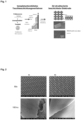
- the SEM image shows a mesoporously templated RuIrTiO x layer calcined at 450 °C on a titanium mesh in top view.
- Fig. 2 is the representation of SEM images of titanium meshes, which can be used preferably as gas diffusion layers.
- the image shows a titanium mesh before (A) and after (B) a coating with mesoporous iridium oxide layers.
- the images arranged above show the meshes at 50x magnification.
- the images arranged below, however, show the meshes at 100,000x magnification.
- the coating was calcined in air at 400 °C.
- Fig. 3 shows a schematic flow diagram of a preferred method for producing a catalyst-coated three-dimensionally structured electrode in comparison with a method from the prior art.
- an ink is produced.
- a dispersion comprising preferably isopropanol ( iPrOH ), Nafion, water and a catalyst powder is ultrasonically mixed to an ink.
- a substrate such as a Nafion membrane, is then coated with the ink. The substrate is preferably coated by spraying.
- the membrane is introduced into the full-cell scale.
- the method according to the invention preferably uses dip coating.
- a suspension is generated which comprises, for example, ethanol, a micelle-forming template and a noble metal salt, namely Ir(OAc) 3.
- a three-dimensional substrate is then immersed in a container with the suspension described. Pulling the three-dimensional substrate out of the suspension leads to a layer of a catalyst precursor on the substrate.
- a catalyst layer is then formed using thermal treatment and in a final process step the three-dimensional substrate is introduced into a full-cell scale.
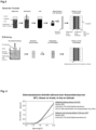
- Fig. 4 shows the electrocatalytic activity of a CCG (catalyst coated gas diffusion layer) coated with mesoporous iridium oxide as an anode in contact with a membrane.
- the membrane is coated on the cathode side with a common Pt/C catalyst (CCM coated on one side).
- CCM catalyst-coated membrane
- CCM coated on both sides a reference system.
- the CCG system achieves a geometric current density that is about twice as high as that of the binder-containing commercial reference.
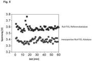
- the in Fig. 5 The illustrated dot diagram shows an increased catalytic activity of three-dimensionally structured electrodes with mesoporous templated catalyst layers in chlorine production.
- a reference catalyst was used, whereby a three-dimensionally structured electrode was coated using a conventional synthesis process and therefore does not contain a templated mesoporous catalyst layer.
Landscapes
- Chemical & Material Sciences (AREA)
- Engineering & Computer Science (AREA)
- Chemical Kinetics & Catalysis (AREA)
- Electrochemistry (AREA)
- Materials Engineering (AREA)
- Organic Chemistry (AREA)
- Metallurgy (AREA)
- General Chemical & Material Sciences (AREA)
- Physics & Mathematics (AREA)
- Thermal Sciences (AREA)
- Inorganic Chemistry (AREA)
- Manufacturing & Machinery (AREA)
- Mechanical Engineering (AREA)
- Ceramic Engineering (AREA)
- Catalysts (AREA)
- Inert Electrodes (AREA)
- Electrolytic Production Of Non-Metals, Compounds, Apparatuses Therefor (AREA)
- Electrodes For Compound Or Non-Metal Manufacture (AREA)
Description
Die Erfindung betrifft ein Verfahren zur Herstellung einer katalysatorbeschichteten dreidimensional strukturierten Elektrode. In einem ersten Verfahrensschritt wird ein dreidimensional strukturiertes Metallsubstrat bereitgestellt. Anschließend wird eine mesoporöse Katalysatorschicht auf das dreidimensional strukturierte Metallsubstrat synthetisiert. Die Synthese erfolgt bevorzugt indem zunächst eine Lösung oder Suspension aus einem Templat, einem Metall-Präkursor und einem Lösungsmittel generiert wird. Anschließend wird die Lösung oder Suspension auf das dreidimensional strukturierte Metallsubstrat aufgetragen, sodass sich ein Film auf dem dreidimensional strukturierte Metallsubstrat bildet. Danach wird das dreidimensional strukturierte Metallsubstrat bei einer Temperatur T1 getrocknet, sodass das Lösungsmittel innerhalb des Films verdampft und eine Schicht einer Katalysatorvorstufe mit integrierten Templatstrukturen erhalten wird. Abschließend wird das Katalysatorvorstufen umfassende dreidimensional strukturierte Metallsubstrat einer thermischen Behandlung unterzogen, sodass eine mesoporöse Katalysatorschicht entsteht.The invention relates to a method for producing a catalyst-coated three-dimensionally structured electrode. In a first method step, a three-dimensionally structured metal substrate is provided. A mesoporous catalyst layer is then synthesized on the three-dimensionally structured metal substrate. The synthesis is preferably carried out by first generating a solution or suspension from a template, a metal precursor and a solvent. The solution or suspension is then applied to the three-dimensionally structured metal substrate so that a film forms on the three-dimensionally structured metal substrate. The three-dimensionally structured metal substrate is then dried at a temperature T 1 so that the solvent evaporates within the film and a layer of a catalyst precursor with integrated template structures is obtained. Finally, the three-dimensionally structured metal substrate comprising catalyst precursors is subjected to a thermal treatment so that a mesoporous catalyst layer is formed.
Darüber hinaus betrifft die Erfindung eine Elektrode, welche durch das Verfahren eingangs genannter Art hergestellt wurde, sowie eine elektrochemische Zelle mit einer solchen Elektrode.Furthermore, the invention relates to an electrode which was produced by the method of the type mentioned at the outset, as well as to an electrochemical cell with such an electrode.
In Elektrolysezellen für die Wasserspaltung sowie Brennstoffzellen zur Rückverstromung gasförmigen Wasserstoffs, werden üblicherweise mit einem Binder dispergierte Katalysatorpulver auf eine Membran mittels Sprüh-, Siebdruck-, oder Rakelverfahren aufgetragen. Derartige Verfahren sind bspw. aus den Druckschriften
Bei der Herstellung einer Katalysatorschicht mit den oben genannten Techniken gelingt es nicht, eine gleichmäßige Beschichtung mit einstellbarer Porosität und ohne den Einsatz eines Binders zu realisieren. Dabei zeigen im Halbzellmaßstab insbesondere binderfreie und mesoporös templatierte Anodenmaterialien verbesserte Aktivitäten in der Sauerstoffevolution (OER). Es hat sich gezeigt, dass Iridiumhaltige mesoporöse Schichten eine deutlich höhere Ir-Massenaktivität als vergleichbare binderbasierte und über Ink-Methoden hergestellte Katalysatorschichten erreichen (vgl. auch
Eine direkte Beschichtung der Membran mit einem binderfreien mesoporös templatierten Katalysator ist nicht möglich, da die Synthese eines solchen Katalysators (ohne Binder) eine thermische Behandlung erfordert. Die thermische Behandlung führt zur Zerstörung der Membran.A direct coating of the membrane with a binder-free mesoporous templated catalyst is not possible, since the synthesis of such a catalyst (without binder) requires thermal treatment. The thermal treatment leads to the destruction of the membrane.
Um dennoch die hochaktiven Katalysatorschichten in einen Elektrolyseur oder einer Brennstoffzelle einzusetzen, musste daher eine alternative Methode gefunden werden, die eine Überführung der mesoporösen Schicht aus dem Halb- in den Vollzellmaßstab ermöglicht.In order to use the highly active catalyst layers in an electrolyzer or a fuel cell, an alternative method had to be found that enables the mesoporous layer to be transferred from the half-cell to the full-cell scale.
In der
In der
In
Mithin liegt ein Bedarf vor, eine effiziente Katalysatorschicht zu erhalten, insbesondere im Zusammenhang einer Beschichtung für Elektroden.Therefore, there is a need to obtain an efficient catalyst layer, especially in the context of a coating for electrodes.
Die Aufgabe der Erfindung war es daher die Nachteile aus dem Stand der Technik zu beseitigen und eine elektrochemische Zelle bereitzustellen, welche eine hochaktive binderfreie mesoporös templatierte Katalysatorschicht umfasst. Insbesondere war die Aufgabe der Erfindung eine Elektrode für eine derartige elektrochemische Zelle und ein Verfahren zur Herstellung dieser Elektrode bereitzustellen.The object of the invention was therefore to eliminate the disadvantages of the prior art and to provide an electrochemical cell which comprises a highly active binder-free mesoporous templated catalyst layer. In particular, the object of the invention was to provide an electrode for such an electrochemical cell and a method for producing this electrode.
Die erfindungsgemäße Aufgabe wird gelöst durch die Merkmale der unabhängigen Ansprüche. Vorteilhafte Ausgestaltungen der Erfindung sind in den abhängigen Ansprüchen beschrieben.The object of the invention is achieved by the features of the independent claims. Advantageous embodiments of the invention are described in the dependent claims.
In einer bevorzugten Ausführungsform betrifft die Erfindung ein Verfahren zur Herstellung einer katalysatorbeschichteten dreidimensional strukturierten Elektrode umfassend die nachfolgenden Schritte:
- a) Bereitstellung eines dreidimensional strukturierten Metallsubstrats;
- b) Herstellung einer Suspension umfassend ein Templat, einen Metall-Präkursors und ein Lösungsmittel;
- c) Auftragen der Suspension auf das dreidimensional strukturierte Metallsubstrat, sodass sich ein Suspensionsfilm auf dem dreidimensional strukturierten Metallsubstrat bildet;
- d) Trocknen des Suspensionsfilms auf dem dreidimensional strukturierten Metallsubstrat bei einer Temperatur T1, in einem Bereich zwischen 18°C-250°C, sodass das Lösungsmittel innerhalb des Suspensionsfilmes verdampft und eine Schicht einer Katalysatorvorstufe mit integrierten Templatstrukturen erhalten wird;
- e) thermische Behandlung des die Katalysatorvorstufe umfassenden dreidimensional strukturierte Metallsubstrats bei einer zweiten Temperatur T2, in einem Bereich zwischen 200°C und 1000°C und einer Kalzinierzeit t2, in einem Bereich zwischen 1 Minute und 1440 Minuten, sodass eine mesoporöse Katalysatorschicht entsteht.
- a) providing a three-dimensionally structured metal substrate;
- b) preparing a suspension comprising a template, a metal precursor and a solvent;
- c) applying the suspension to the three-dimensionally structured metal substrate so that a suspension film is formed on the three-dimensionally structured metal substrate;
- d) drying the suspension film on the three-dimensionally structured metal substrate at a temperature T 1 , in a range between 18°C-250°C, so that the solvent within the suspension film evaporates and a layer of a catalyst precursor with integrated template structures is obtained;
- e) thermal treatment of the three-dimensionally structured metal substrate comprising the catalyst precursor at a second temperature T 2 in a range between 200°C and 1000°C and a calcination time t 2 in a range between 1 minute and 1440 minutes, so that a mesoporous catalyst layer is formed.
Das erfindungsgemäße Verfahren gestaltet sich als eine Abkehr vom Stand der Technik, denn Katalysatoren werden nicht -wie häufig angewendet- über eine binderbasierte Dispersion mittels geeignetem Verfahren (Sprühen, Pinseln, Siebdrucken, Rakeln) auf ein Substrat aufgetragen, sondern binderfrei und mit definierter Porenstrukturen auf einem dreidimensionales Substrat abgeschieden (Tauchbeschichtung) und anschließend in einem Vollzellmaßstab implementiert. Der Verzicht eines Binders führt dabei vorteilhaft zu keiner Verringerung der volumenbezogenen elektrischen Leitfähigkeit des katalytisch aktiven Materials - entgegen der bekannten Binder umfassenden Katalysatoren aus dem Stand der Technik. Demnach wird mit dem erfindungsgemäßen Verfahren eine höhere Katalysatoreffizienz erhalten. Darüber hinaus führen dicht gepackte Porenstrukturen zu einer rissfreien Beschichtung und im Falle kleiner Mesoporen, zum bestmöglichsten Mittelweg aus Oberfläche und Zugänglichkeit von Edukten und Produkten unter Vermeidung von DiffusionslimitierungenThe process according to the invention is a departure from the state of the art, because catalysts are not applied to a substrate via a binder-based dispersion using a suitable process (spraying, brushing, screen printing, doctor blade coating), as is often the case, but are deposited on a three-dimensional substrate without a binder and with defined pore structures (dip coating) and then implemented on a full-cell scale. The absence of a binder advantageously does not lead to a reduction in the volume-related electrical conductivity of the catalytically active material - in contrast to the known catalysts from the state of the art that contain binders. Accordingly, a higher catalyst efficiency is achieved with the process according to the invention. In addition, densely packed pore structures lead to a crack-free coating and, in the case of small mesopores, to the best possible compromise between surface area and accessibility of reactants and products while avoiding diffusion limitations.
Es hat sich gezeigt, dass der Einsatz dreidimensional strukturierter Elektroden wesentliche Vorteile in verschieden Anwendungsfällen, insbesondere in der Anwendung innerhalb von elektrochemischen Zellen, mit sich bringt. Dreidimensional strukturierte Elektroden weisen eine besonders große spezifische Oberfläche pro Volumeneinheit auf, welche somit eine verbesserte Interaktion der Elektrode mit einem ihr umgebenen Medium ermöglicht. Insbesondere kann vorteilhafterweise ein verbesserter Gasblasenabtransport ermöglicht werden durch die vergrößerte Oberfläche pro Volumeneinheit. Ein Verfahren zur Herstellung einer dreidimensional strukturierten Elektrode mit einer nanostrukturierten mesoporös templatierten Katalysatorschicht war aus dem Stand der Technik bisher weder bekannt noch nahegelegt.It has been shown that the use of three-dimensionally structured electrodes offers significant advantages in various applications, especially in Application within electrochemical cells. Three-dimensionally structured electrodes have a particularly large specific surface area per unit volume, which thus enables improved interaction of the electrode with a medium surrounding it. In particular, improved gas bubble removal can advantageously be enabled by the increased surface area per unit volume. A method for producing a three-dimensionally structured electrode with a nanostructured mesoporous templated catalyst layer was previously neither known nor suggested from the prior art.
Wie schon eingangs erörtert, liegt ein wesentlicher Vorteil der vorliegenden Erfindung in der binderfreien Herstellung eines Katalysators. Binder sind üblicherweise notwendig, um eine mechanische Haftung der Partikel eines Katalysatorpulvers sowohl zueinander als auch zu einem Substrat sowie - wie im Falle der Wasserelektrolyse - einen raschen Protonentransport zu gewährleisten. Das erfindungsgemäße Verfahren führt zu kovalent gebundenen Netzwerken des Katalysators, wodurch -binderfrei- ein ausreichender innerer struktureller Zusammenhalt erzeugt wird. Ein wesentlicher Nachteil des Binders besteht in der Herabsetzung der Elektronenleitfähigkeit, wodurch die katalytische Effizienz aktiver Zentren merklich reduziert wird. Ein weiterer Nachteil des Binders ist die Blockierung aktiver Zentren.As already discussed at the beginning, a significant advantage of the present invention is the binder-free production of a catalyst. Binders are usually necessary to ensure mechanical adhesion of the particles of a catalyst powder both to each other and to a substrate and - as in the case of water electrolysis - rapid proton transport. The process according to the invention leads to covalently bonded networks of the catalyst, which - without binders - creates sufficient internal structural cohesion. A significant disadvantage of the binder is the reduction in electron conductivity, which noticeably reduces the catalytic efficiency of active centers. Another disadvantage of the binder is the blocking of active centers.
Im Sinne der Erfindung ist ein dreidimensional strukturiertes Substrat bevorzugt in der Form ausgestaltet, dass es eine räumliche Struktur, also eine Ausdehnung in jede Raumrichtung, annimmt. Unter der Begriffsfolge ist bevorzugt eine dreidimensionale, d.h. räumliche, Anordnung von Strukturelementen innerhalb (oder auch auf der Oberfläche) eines Substrats zu verstehen. Die Geometrie einer dreidimensionalen Strukturierung zielt vorteilhaft darauf ab, eine erhöhte Oberfläche pro Substratvolumen zu ermöglichen. Dies kann beispielsweise durch regelmäßige Poren, Erhebungen, Vertiefungen, Öffnungen in einem dreidimensionalen Substrat erfolgen. Eine erhöhte Oberfläche führt vorteilhaft zu einer verbesserten Interaktion des Substrats mit seinem umgebenden Medium.In the sense of the invention, a three-dimensionally structured substrate is preferably designed in such a way that it assumes a spatial structure, i.e. an extension in every spatial direction. The sequence of terms is preferably understood to mean a three-dimensional, i.e. spatial, arrangement of structural elements within (or on the surface) of a substrate. The geometry of a three-dimensional structuring advantageously aims to enable an increased surface area per substrate volume. This can be achieved, for example, by regular pores, elevations, depressions, openings in a three-dimensional substrate. An increased surface area advantageously leads to improved interaction of the substrate with its surrounding medium.
Das dreidimensional strukturierte Metallsubstrat wird bevorzugt in einem dem Verfahren vorgelagerten Schritt gereinigt bzw. vorbehandelt. Insbesondere kann eine derartige Vorbehandlung durch Ätzung bewerkstelligt werden. Dies führt zu einer verbesserten Haftung der später aufgetragenen mesoporösen Katalysatorschicht, da vorteilhaft nicht-gewünschte Oxide und Schmutz entfernt wird. Es versteht sich, dass die Vorbehandlung auch durch weitere Verfahren zur Entfernung von Oxiden und Schmutz erfolgen kann.The three-dimensionally structured metal substrate is preferably cleaned or pretreated in a step preceding the process. In particular, such pretreatment can be accomplished by etching. This leads to a improved adhesion of the mesoporous catalyst layer applied later, since unwanted oxides and dirt are advantageously removed. It goes without saying that the pretreatment can also be carried out using other processes for removing oxides and dirt.
Die Kombination der vorliegenden Verfahrensschritte führt zu einem überraschenden Synergieeffekt, der zu den vorteilhaften Eigenschaften und dem damit einhergehenden Gesamterfolg der Erfindung führt, wobei die einzelnen Merkmale in Wechselwirkung zueinander stehen. Ein wichtiger Vorteil des erfindungsgemäßen Verfahrens ist zudem die überaus schnelle, reproduzierbare und wirtschaftliche Syntheseprozedur.The combination of the present process steps leads to a surprising synergistic effect, which leads to the advantageous properties and the associated overall success of the invention, with the individual features interacting with one another. Another important advantage of the process according to the invention is the extremely fast, reproducible and economical synthesis procedure.
Die Verwendung eines dreidimensional strukturierten Metall-Substrats war für einen Fachmann fernliegend. Aufgrund der thermischen Behandlung innerhalb der Syntheseprozedur, war davon auszugehen, dass das dreidimensional strukturierte Metall-Substrat einen Verzug erleidet. Weiterhin war zu erwarten, dass eine thermische Behandlung des dreidimensionalen Metallsubstrats zu nachteiligen Eigenspannungen und unter Umständen zu Rissen innerhalb des Materials führt. Insbesondere Gitterstrukturen, Netze etc. weisen dünne Maschen auf, die keinen hohen Temperaturen standhalten.The use of a three-dimensionally structured metal substrate was far-fetched for a specialist. Due to the thermal treatment within the synthesis procedure, it was to be assumed that the three-dimensionally structured metal substrate would suffer from distortion. It was also to be expected that thermal treatment of the three-dimensional metal substrate would lead to disadvantageous internal stresses and, under certain circumstances, to cracks within the material. In particular, lattice structures, nets, etc. have thin meshes that cannot withstand high temperatures.
Daher war es für die Erfinder überraschend, dass der Einfluss der aufgetragenen Suspension ein derartiges Materialverhalten im großen Maße verhindert. Es war nicht zu erwarten, dass die aufgetragene Suspension/Katalysatorvorstufe neben den (später -nach der thermischen Behandlung- erhaltenen) vorteilhaften Eigenschaften als hochaktiver Katalysator in elektrochemischen Zellen auch eine Schutzwirkung auf die Elektrode im Zusammenhang mit einer thermischen Behandlung aufweist.It was therefore surprising to the inventors that the influence of the applied suspension prevented such material behavior to a large extent. It was not to be expected that the applied suspension/catalyst precursor would have a protective effect on the electrode in connection with a thermal treatment in addition to the advantageous properties as a highly active catalyst in electrochemical cells (obtained later - after the thermal treatment).
Es hat sich zudem vorteilhaft gezeigt, dass die Suspension an sämtlichen geometrischen Formen (Fortsätzen, Hinterschneidungen, Rundungen, Erhebungen etc.) des strukturierten dreidimensionalen Substrats homogen und gleichmäßig nach dem Auftragen, bevorzugt einer Tauchbeschichtung, vorliegt. Insbesondere im Vergleich mit einem Substrat, welches eine durchgängig planar ausgestaltete Fläche aufweist, führt das dreidimensional strukturierte Substrat zu einer verbesserten Haftung der Suspension.It has also been shown to be advantageous that the suspension is present homogeneously and evenly on all geometric shapes (extensions, undercuts, curves, elevations, etc.) of the structured three-dimensional substrate after application, preferably by dip coating. In particular, in comparison with a substrate that has a consistently planar surface, the three-dimensionally structured substrate leads to improved adhesion of the suspension.
Überraschend war, dass beim Tauchbeschichten das Auftreten sogenannter Randeffekte nicht besonders ausgeprägt war. Obwohl bekannt ist, dass Randeffekte zu dickeren Filmsegmenten führen können, gelingt bei Einstellung der richtigen Zusammensetzung Beschichtungen mit homogener Schichtdicke zu erhalten.What was surprising was that the occurrence of so-called edge effects was not particularly pronounced during dip coating. Although it is known that edge effects can lead to thicker film segments, coatings with a homogeneous layer thickness can be obtained by setting the right composition.
In weiteren bevorzugten Ausführungsformen kann auch eine Lösung umfassend ein Templat, einen Metall-Präkursor und ein Lösungsmittels in Schritt b) hergestellt werden.In further preferred embodiments, a solution comprising a template, a metal precursor and a solvent can also be prepared in step b).
In weiteren bevorzugten Ausführungsformen können auch mehrere Template, Metall-Präkursoren und/oder Lösungsmittel eingesetzt werden. Weiterhin ist bevorzugt das Templat ein Porentemplat.In further preferred embodiments, several templates, metal precursors and/or solvents can be used. Furthermore, the template is preferably a pore template.
Der bevorzugte Film kann ausgewählt sein aus einer Gruppe umfassend ein Lösungsfilm (Film durch eine Lösung) oder ein Suspensionsfilm (Film durch eine Suspension).The preferred film may be selected from a group comprising a solution film (film through a solution) or a suspension film (film through a suspension).
Ebenfalls ist es bevorzugt, dass in Schritt e) mehrere mesoporöse Katalysatorschichten entstehen.It is also preferred that several mesoporous catalyst layers are formed in step e).
Es hat sich als vorteilhaft gezeigt, dass die über Tauchbeschichtung hergestellten mesoporösen Beschichtungen besonders gut auf dem Substrat hält. Testungen der Haftung via Tapetest zeigten, dass sie das Schichtmaterial schlecht vom Substrat ablösen lässt. Im Vergleich zeigen beispielsweise besprühte Substrate, die unter den gleichen Bedingungen thermisch behandelt wurden, eine deutlich schlechtere Haftung. Dies kann mit der gleichmäßigen Filmmorphologie erklärt werden. Auch mehrlagige Beschichtungen zeigten eine gute Haftung. Ein weiterer Vorteil ist die Möglichkeit, dass die mesoporösen Beschichtungen sich gut in mehreren Lagen aufbringen lassen. Somit kann beispielsweise bei der Tauchbeschichtung eine gewünschte geometrische Metallbeladung in einem breiten Bereich gezielt eingestellt werden. Die mesoporöse Morphologie hilft dabei eine hohe geometrische Beladung zu erreichen, da die poröse Struktur Verspannungen innerhalb der Schicht besser kompensieren kann. Während der Kalzinierung / der Entfernung des Templates schrumpft der Film entlang der Flächennormalen (es entstehen ellipsoide Poren), dabei werden Spannungen innerhalb der Schicht kompensiert, die zu einem Ablösen der Schicht führen könnten. Dabei war es überraschend, dass durch den bevorzugten Einsatz eines Templats insbesondere mehrlagige mesoporöse Katalysatorschichten bereitgestellt werden konnten, mit der besonders effizient eine Elektrolyse durchführbar war.It has been shown to be advantageous that the mesoporous coatings produced by dip coating adhere particularly well to the substrate. Adhesion tests using a wallpaper test showed that the layer material is difficult to remove from the substrate. In comparison, for example, sprayed substrates that were thermally treated under the same conditions show significantly poorer adhesion. This can be explained by the uniform film morphology. Multi-layer coatings also showed good adhesion. Another advantage is the possibility that the mesoporous coatings can be applied well in several layers. This means that, for example, a desired geometric metal loading can be specifically set over a wide range during dip coating. The mesoporous morphology helps to achieve a high geometric loading, as the porous structure can better compensate for tensions within the layer. During calcination / removal of the template, the film shrinks along the surface normal (ellipsoidal pores are formed), This compensates for tensions within the layer that could lead to the layer detaching. It was surprising that the preferred use of a template made it possible to provide multilayer mesoporous catalyst layers, which made electrolysis particularly efficient.
Insbesondere der Einsatz eines Metallsubstrats ist vorteilhaft dazu geeignet, geometrisch eine dreidimensional strukturierte Form anzunehmen, wobei das Substrat aufgrund des Werkstoffes (Metall) weiterhin eine ausreichend hohe Steifigkeit aufweist. Dies ermöglicht eine stabile Ausgestaltung eines Substrats, welches Zug und Druckbelastungen standhalten kann und somit für den Einbau in einen Vollzellmaßstab besonders simpel ohne Schäden geeignet ist. Darüber hinaus ist Metall sehr gut bearbeitbar, sodass sämtliche geometrische Formen durch das Metallsubstrat angenommen werden können.In particular, the use of a metal substrate is advantageous for adopting a geometrically three-dimensionally structured form, whereby the substrate continues to have a sufficiently high rigidity due to the material (metal). This enables a stable design of a substrate that can withstand tensile and compressive loads and is therefore particularly suitable for installation in a full cell scale without damage. In addition, metal is very easy to work with, so that all geometric shapes can be assumed by the metal substrate.
In einer bevorzugten Ausführungsform umfasst das Metallsubstrat ein Metall ausgesucht aus der Gruppe umfassend: Nickel, Silber, Titan, Eisen, Mangan, Kobalt, Gold, Iridium, Kupfer, Platin, Palladium, Osmium, Rhodium, Ruthenium, Aluminium, Wolfram, Zinn, Zink, Blei, Germanium, Silizium sowie deren Legierungen. Die vorgenannten Materialien sind vorteilhaft, weil diese im Allgemeinen eine gute elektrische Leitfähigkeit, zugleich aber auch durch eine gute chemische Stabilität gegenüber einen umgebenen Medium, insbesondere im Einsatz von Elektrolysezellen oder Galvanischen Zellen, aufweisen. Es versteht sich, dass das Metallsubstrat auch Kombinationen vorgenannter Materialien umfasst.In a preferred embodiment, the metal substrate comprises a metal selected from the group comprising: nickel, silver, titanium, iron, manganese, cobalt, gold, iridium, copper, platinum, palladium, osmium, rhodium, ruthenium, aluminum, tungsten, tin, zinc, lead, germanium, silicon and their alloys. The aforementioned materials are advantageous because they generally have good electrical conductivity, but at the same time also have good chemical stability with respect to a surrounding medium, in particular when used in electrolysis cells or galvanic cells. It goes without saying that the metal substrate also comprises combinations of the aforementioned materials.
In einer bevorzugten Ausführungsform ist das Verfahren dadurch gekennzeichnet, dass mesoporöse Katalysatorschichten auf dreidimensional strukturierten Ti-Substraten mit unterschiedlicher Geometrie hergestellt werden. Gerade Ti-Substrate sind bevorzugt geeignet, da sie über eine natürliche dünne Oxidschicht auf der Oberfläche verfügen. Beschichtet man nun diese Substrate, können auf der Substratoberfläche vorhandene Sauerstofffunktionen während der thermischen Behandlung eine kovalente und/oder ionische Bindungen mit der Katalysatorschicht eingehen, wodurch starke mechanische Haftung resultiert.In a preferred embodiment, the method is characterized in that mesoporous catalyst layers are produced on three-dimensionally structured Ti substrates with different geometries. Ti substrates in particular are particularly suitable because they have a naturally thin oxide layer on the surface. If these substrates are then coated, oxygen functions present on the substrate surface can form covalent and/or ionic bonds with the catalyst layer during the thermal treatment, resulting in strong mechanical adhesion.
In einer bevorzugten Ausführungsform umfasst das Metallsubstrat auch weitere elektrisch leitfähige Materialien ausgesucht aus der Gruppe umfassend Glaskohlenstoff, Bor-dotierter-Diamant, Carbide, Nitride, Oxide. Diese liegen bevorzugt in kleineren Mengen im Metallsubstrat vor, wobei kleinere Mengen ein Bereich von bevorzugt kleiner Volumenprozente des Gesamtsubstrats beschreibt. In weiteren bevorzugten Ausführungsformen umfasst das Metallsubstrat im Wesentlichen vollständig einen oder mehrere der genannten elektrisch leitfähigen Materialien.In a preferred embodiment, the metal substrate also comprises other electrically conductive materials selected from the group comprising glassy carbon, boron-doped diamond, carbides, nitrides, oxides. These are preferably in smaller amounts in the metal substrate, with smaller amounts describing a range of preferably small volume percentages of the total substrate. In further preferred embodiments, the metal substrate essentially completely comprises one or more of the electrically conductive materials mentioned.
Bevorzugt ist die synthetisierte mesoporöse Katalysatorschicht nanostrukturiert. Unter einer Nanostrukturierung ist bevorzugt die Strukturierung eines Festkörpers auf atomarem Niveau zu verstehen. Durch gezielte Modifikation (Implantation) werden atomare, chemische usw. meist oberflächennahe Festkörpereigenschaften verändert.The synthesized mesoporous catalyst layer is preferably nanostructured. Nanostructuring is preferably understood to mean the structuring of a solid at the atomic level. Through targeted modification (implantation), atomic, chemical, etc., mostly near-surface solid properties are changed.
Eine nanostrukturierte mesoporöse Katalysatorschicht ist bevorzugt als eine geordnete Nanostruktur der mesoporösen Katalysatorschicht zu verstehen. Das bedeutet, dass einer Katalysatorschicht wiederholend (periodisch) in gleicher Weise in etwa gleiche Strukturelemente umfasst sind (bspw. aneinandergereiht). Es hat sich überraschend gezeigt, dass die Ausbildung einer geordneten Mesostruktur durch die geometrische Ausgestaltung (bspw. Wölbung, Vertiefung) der Substratoberfläche nicht gestört wird.A nanostructured mesoporous catalyst layer is preferably understood as an ordered nanostructure of the mesoporous catalyst layer. This means that a catalyst layer is comprised of approximately identical structural elements in a repetitive (periodic) manner (e.g. arranged in a row). Surprisingly, it has been shown that the formation of an ordered mesostructure is not disturbed by the geometric configuration (e.g. curvature, depression) of the substrate surface.
Weiterhin bevorzugt wird ein oder mehrere Metallsalze als Katalysatorvorstufe zusammen mit einem oder mehreren Template in einem oder mehreren geeigneten Lösungsmitteln dispergiert und diese Mischung auf das dreidimensionale Metallsubstrat überführt. Das nachfolgende Verdampfen des Lösungsmittels führt zu einer vorteilhaften periodischen Anordnung des Templats umgeben von einer Katalysatorvorstufe. Eine anschließende thermische Behandlung bei bevorzugten Temperaturen zwischen 300 °C - 800 °C verbrennt das Templat und überführt die Vorstufe in den eigentlichen Katalysator, bevorzugt ein Metalloxid. Durch die Entfernung des Templats entstehen Poren, die miteinander verknüpft sind und besonders vorteilhaft eine hohe Oberfläche für katalytische Prozesse zur Verfügung stellen.Furthermore, one or more metal salts are preferably dispersed as a catalyst precursor together with one or more templates in one or more suitable solvents and this mixture is transferred to the three-dimensional metal substrate. The subsequent evaporation of the solvent leads to an advantageous periodic arrangement of the template surrounded by a catalyst precursor. A subsequent thermal treatment at preferred temperatures between 300 °C - 800 °C burns the template and converts the precursor into the actual catalyst, preferably a metal oxide. The removal of the template creates pores that are linked to one another and particularly advantageously provide a high surface area for catalytic processes.
Der bevorzugte Syntheseansatz basiert auf Templaten die als Platzhalter für ein gewünschtes Porengefüge dienen. Während der Synthese wird das Templat vom umgebenden Material (Katalysatorvorstufe) eingeschlossen und hinterlässt nach Entfernung ein definiert poröses Material. Abhängig von der Templatgröße entstehen Porenstrukturen mit Porengrößen von einigen Mikrometern bis zu wenigen Nanometern. Materialien mit einer geordneten Porenstruktur und einer monomodalen Porengrößenverteilung können demnach bevorzugt über sogenannte Templatierungsverfahren synthetisiert werden. Bei diesem Syntheseansatz dienen Template als Platzhalter für die gewünschte Porenform. Durch den Einsatz eines Templats konnte eine besonders vorteilhafte Porenmorphologie der Katalysatorschicht bereitgestellt werden. Insbesondere konnte die Katalysatorschicht als mesoporös ausgestaltet werden, wodurch eine besonders hohe mechanische Stabilität erreicht werden konnte. Weiterhin war der Einsatz des Templats dahingehend von Vorteil, dass eine gezielt einstellbare, reproduzierbar generierbare Porenverteilung mit besonders hoher spezifischer Oberfläche der Katalysatorschicht bereitgestellt werden konnte. Insbesondere im Hinblick auf technische Anwendungen stellt die Reproduzierbarkeit einen besonders ausgeprägten Vorteil dar.The preferred synthesis approach is based on templates that serve as placeholders for a desired pore structure. During synthesis, the template is enclosed by the surrounding material (catalyst precursor) and leaves behind a defined porous material after removal. Depending on the template size, pore structures with pore sizes from a few micrometers to a few Nanometers. Materials with an ordered pore structure and a monomodal pore size distribution can therefore preferably be synthesized using so-called templating processes. In this synthesis approach, templates serve as placeholders for the desired pore shape. By using a template, a particularly advantageous pore morphology of the catalyst layer could be provided. In particular, the catalyst layer could be designed as mesoporous, which made it possible to achieve a particularly high level of mechanical stability. The use of the template was also advantageous in that a specifically adjustable, reproducibly generated pore distribution with a particularly high specific surface area of the catalyst layer could be provided. Reproducibility is a particularly pronounced advantage, particularly with regard to technical applications.
In weiteren bevorzugten Ausführungsformen umfasst das Templat bevorzugt Tenside, Block-Copolymere und/oder dendritische Kern-Schalenpolymere. Das Templat führt zu vorteilhaften mesoporösen Strukturierungen innerhalb der Katalysatorschicht, wobei das Templat Mizellen bilden oder aber auch andere Strukturierungen aufweisen kann. Das Templat kann in weiteren Alternativen auch ein nicht Mizellen bildendes Kern-Schale-Makromolekül, gewissermaßen eine unimolekulare Mizelle, umfassen. Weiterhin können Block-Copolymere auch lamellare Strukturen annehmen.In further preferred embodiments, the template preferably comprises surfactants, block copolymers and/or dendritic core-shell polymers. The template leads to advantageous mesoporous structures within the catalyst layer, whereby the template can form micelles or also have other structures. In further alternatives, the template can also comprise a core-shell macromolecule that does not form micelles, a kind of unimolecular micelle. Furthermore, block copolymers can also assume lamellar structures.
In einer bevorzugten Ausführungsform sind Template als Softtemplate ausgestaltet. Softtemplate sind verformbare strukturdirigierende Einheiten. Dies können Mizellen oder lamellare Strukturen aus amphiphilen Polymeren (oftmals Block-Copolymere) sein. Typischerweise entstehen die Mizellen oder Lamellen oberhalb einer kritischen Konzentration eines in einem Lösungsmittel dispergierten Polymers. Zu den Softtemplaten gehören auch dendritische oder hyperverzweigte Kern-Schalenpolymere, wobei Kern und Schale der Polymere unterschiedliche Hydrophilizitäten zeigen, somit auch amphiphil sind.In a preferred embodiment, templates are designed as soft templates. Soft templates are deformable structure-directing units. These can be micelles or lamellar structures made of amphiphilic polymers (often block copolymers). The micelles or lamellae typically form above a critical concentration of a polymer dispersed in a solvent. Soft templates also include dendritic or hyperbranched core-shell polymers, where the core and shell of the polymers show different hydrophilicities and are therefore also amphiphilic.
In einer weiteren bevorzugten Ausführungsform sind Template als Hardtemplate ausgestaltet. Hardtemplate sind starre sturkturdirigierende Einheiten. Zu nanostrukturierte Hardtemplaten zählen Metalle, Oxide, oftmals Siliziumoxide (z.B. MCM-Gruppe, SBA-Gruppe, FDU-Gruppe, KIT-Gruppe, MSU-Gruppe, TUD-Gruppe, HMM-Gruppe, FSM-Gruppe) sowie Kohlenstoffe (z.B. CMK-Gruppe). Es kann sich bei diesen Hardtemplaten um einzelne Nanopartikel oder um nanostrukturierte größere Gebilde handeln.In a further preferred embodiment, templates are designed as hard templates. Hard templates are rigid structure-directing units. Nanostructured hard templates include metals, oxides, often silicon oxides (e.g. MCM group, SBA group, FDU group, KIT group, MSU group, TUD group, HMM group, FSM group) and carbons (e.g. CMK group). These hard templates can be individual nanoparticles or larger nanostructured structures.
Der bevorzugte Verfahrensschritt der Trocknung kann in einer bevorzugten Variante auch so ausgestaltet sein, dass die Trocknung in sehr kurzer Zeit erfolgt. Zum Beispiel in einem Zeitbereich vom Auftragen der Suspension oder der Lösung auf das Metallsubstrat bis hin zur thermischen Behandlung. In der Praxis kann sich der Zeitbereich bspw. folgendermaßen ereignen: Herausziehen des dreidimensionalen Metallsubstrats aus einem Behältnis umfassend der Lösung oder Suspension und direktes Einlegen in einen Ofen zur thermischen Behandlung. Ein derartige Durchführen des Trocknungsvorgangs führt einer besonders schnell durchführbaren Synthese der Katalysatorschicht auf das dimensional strukturierte Metall-Substrat.In a preferred variant, the preferred process step of drying can also be designed so that drying takes place in a very short time. For example, in a time range from applying the suspension or solution to the metal substrate to the thermal treatment. In practice, the time range can occur, for example, as follows: pulling the three-dimensional metal substrate out of a container containing the solution or suspension and placing it directly in an oven for thermal treatment. Carrying out the drying process in this way leads to a particularly rapid synthesis of the catalyst layer on the dimensionally structured metal substrate.
In einer weiteren bevorzugten Ausführungsform des Verfahrensschritts der Trocknung kann der Zeitbereich vom Auftragen der Suspension oder der Lösung auf das Metallsubstrat bis hin zur thermischen Behandlung wie folgt ablaufen: Herausziehen des dreidimensionalen Metallsubstrats aus einem Behältnis umfassend der Lösung oder Suspension, Trocknen an der Luft (bspw. für ca. 5 Minuten), daraufhin eine thermische Behandlung, um vorteilhaft verbleibendes Lösungsmittel im Wesentlichen vollständig zu entfernen und/oder die Beschichtung zu stabilisieren.In a further preferred embodiment of the drying process step, the time range from application of the suspension or solution to the metal substrate to the thermal treatment can be as follows: pulling the three-dimensional metal substrate out of a container comprising the solution or suspension, drying in air (e.g. for about 5 minutes), then a thermal treatment in order to advantageously remove remaining solvent essentially completely and/or to stabilize the coating.
In einer weiteren bevorzugten Ausführungsform ist das Verfahren dadurch gekennzeichnet, dass das Auftragen der Lösung oder Suspension aus Schritt (c) anhand einer Tauchbeschichtung erfolgt. Es war nicht naheliegend für den Fachmann, dass durch eine Tauchbeschichtung ein dreidimensional strukturiertes Metallsubstrat mit einer homogenen Katalysatorschicht versehen werden kann, die eine templatierte Porenstruktur aufweist. Eine templatierte Porenstruktur meint bevorzugt den Erhalt einer Porenstruktur (Struktur umfassend Poren) unter Einsatz eines Templats. Ein weiterer Vorteil einer Tauchbeschichtung ist der, dass insbesondere auch Hinterschneidungen eines dreidimensional strukturierten Metallsubstrats in einfacher Weise beschichtet werden können.In a further preferred embodiment, the method is characterized in that the solution or suspension from step (c) is applied by means of a dip coating. It was not obvious to the person skilled in the art that a three-dimensionally structured metal substrate can be provided with a homogeneous catalyst layer having a templated pore structure by means of a dip coating. A templated pore structure preferably means the obtaining of a pore structure (structure comprising pores) using a template. A further advantage of a dip coating is that in particular undercuts of a three-dimensionally structured metal substrate can also be coated in a simple manner.
Mit der Tauchbeschichtung gehen noch weitere Vorteile einher. Es lassen sich zum Beispiel gleichzeitig mehrere dreidimensional strukturierten Metallsubstrate beschichten, was eine besonders wirtschaftliche Produktion ermöglicht. Weiterhin weist eine Tauchbeschichtung eine vorteilhaft sehr kurze Prozesszeit auf, denn ein kurzes Eintauchen in die Lösung oder Suspension ist vorteilhaft schon ausreichend um eine bevorzugte Katalysatorschicht zu erhalten. Darüber hinaus ist eine Tauchbeschichtung sehr ressourcenschonend, da keine Materialverschwendung stattfindet (Lösung oder Suspension ist in einem Behälter). Weiterhin kann es bevorzugt sein, dass die Tauchbeschichtung derart erfolgt, dass das Substrat in einem Behältnis vorgelegt und die Lösung hinein- und wieder heraus transportiert wird.Dip coating has other advantages. For example, several three-dimensionally structured metal substrates can be coated simultaneously, which enables particularly economical production. Dip coating also has an advantageously very short process time, because a Brief immersion in the solution or suspension is advantageously sufficient to obtain a preferred catalyst layer. In addition, dip coating is very resource-efficient, as there is no waste of material (solution or suspension is in a container). Furthermore, it may be preferred that the dip coating is carried out in such a way that the substrate is placed in a container and the solution is transported in and out again.
In einer bevorzugten Ausführungsform ist das Verfahren dadurch gekennzeichnet, dass das dreidimensional strukturierte Metallsubstrat als ein Netz, Schaum, Gitter, Sieb, Gewebe und/oder Geflecht ausgestaltet ist.In a preferred embodiment, the method is characterized in that the three-dimensionally structured metal substrate is designed as a net, foam, grid, sieve, fabric and/or mesh.
Besonders bevorzugt ist dreidimensional strukturierte Metallsubstrat in Form eines Netzes oder eines Gitters ausgeführt. Die bevorzugten und besonders bevorzugten Ausführungsformen als Netz oder Gitter sind vorteilhaft, weil solche Ausführungsformen einfach aus den oben beschriebenen Materialien bezogen werden können. Ferner führen derartige Ausgestaltungen vorteilhaft dazu, dass die Metallsubstrate in simpler Weise verformt werden können.Particularly preferably, the three-dimensionally structured metal substrate is designed in the form of a net or a grid. The preferred and particularly preferred embodiments as a net or grid are advantageous because such embodiments can be easily obtained from the materials described above. Furthermore, such embodiments advantageously lead to the metal substrates being able to be deformed in a simple manner.
In einer bevorzugten Ausführungsform ist das Verfahren dadurch gekennzeichnet, dass die Temperatur T2 in einem Bereich liegt zwischen 200°C und 1000°C, bevorzugt zwischen 300°C und 800°C, und die Kalzinierzeit t2 in einem Bereich liegt zwischen 1 Minute und 1440 Minuten, insbesondere zwischen 10 Minuten bis 120 Minuten, bevorzugt zwischen 10 Minuten bis 60 Minuten. Gerade innerhalb der beschriebenen Parameter kann das Templat vorteilhaft vollständig verbrennen, sodass eine nanostrukturierte mesoporöse Katalysatorschicht erhalten wird.In a preferred embodiment, the process is characterized in that the temperature T 2 is in a range between 200°C and 1000°C, preferably between 300°C and 800°C, and the calcination time t 2 is in a range between 1 minute and 1440 minutes, in particular between 10 minutes and 120 minutes, preferably between 10 minutes and 60 minutes. It is precisely within the parameters described that the template can advantageously burn completely, so that a nanostructured mesoporous catalyst layer is obtained.
In einer weiteren bevorzugten Ausführungsform kann das Templat auch aus der Katalysatorvorstufe mit einem geeigneten Medium herausgelöst/herausgeschwemmt werden. Es versteht sich, dass auch eine Kombination aus Wärmebehandlung und Herauslösen der Template über ein Medium nacheinander erfolgen kann. Sofern Template über ein Medium herausgelöst werden - ohne zu verbrennen - können diese Templatstrukturen bevorzugt weiter verarbeitet und/oder wiederverwendet werden.In a further preferred embodiment, the template can also be dissolved/flushed out of the catalyst precursor using a suitable medium. It goes without saying that a combination of heat treatment and dissolving the templates using a medium can also be carried out one after the other. If templates are dissolved using a medium - without burning - these template structures can preferably be further processed and/or reused.
Um das Templat thermisch zu zersetzten und die anorganische Spezies in ein kristallines Metalloxid umzuwandeln, wird die Katalysatorvorstufe bevorzugt kalziniert.To thermally decompose the template and convert the inorganic species into a crystalline metal oxide, the catalyst precursor is preferentially calcined.
Die Kalzinierung führt zu einem drastischen Volumenverlust der Schicht, verursacht durch die Umwandlung des Vorläufers ins Oxid, der Verbrennung des Templats und der Umwandlung der amorphen Porenwand zu einem kristallinen Material. Da die Haftung der Schicht auf dem Substrat vergleichsweise stark ist, u.a. durch kovalente Bindungen zwischen der Substratoberfläche und der Metalloxid-Spezies, kommt es zu einer Kontraktion der Schicht ausschließlich senkrecht zum Substrat, ohne dass die Schicht reißt.Calcination leads to a drastic loss of volume of the layer, caused by the conversion of the precursor into oxide, the combustion of the template and the conversion of the amorphous pore wall into a crystalline material. Since the adhesion of the layer to the substrate is comparatively strong, among other things due to covalent bonds between the substrate surface and the metal oxide species, the layer contracts exclusively perpendicular to the substrate without the layer cracking.
Alle in diesem Dokument offenbarten Parameterbereiche, wie bspw. Temperaturen, Kräfte, Drücke, Abstände etc., umfassen selbstverständlich alle Werte innerhalb der angegebenen Bereiche sowie deren maximalen und minimalen Grenzwerte. Es ist für einen Fachmann ersichtlich, dass die Werte auch gewissen Schwankungen unterliegen. Im vorliegenden Fall handelt sich demnach um einen Temperaturbereich von etwa 200°C bis 1000°C, und bevorzugt etwa 300°C bis 800°C und einer Kalzinierzeit von bevorzugt etwa 1 Minute bis 1440 Minuten, insbesondere etwa 10 bis 120 Minuten. Dies lässt sich auch auf alle weiteren Parameterbereiche des Dokumentes analog übertragen.All parameter ranges disclosed in this document, such as temperatures, forces, pressures, distances, etc., naturally include all values within the specified ranges as well as their maximum and minimum limits. It is clear to a person skilled in the art that the values are also subject to certain fluctuations. In the present case, this is a temperature range of approximately 200°C to 1000°C, and preferably approximately 300°C to 800°C and a calcination time of preferably approximately 1 minute to 1440 minutes, in particular approximately 10 to 120 minutes. This can also be applied analogously to all other parameter ranges in the document.
Begriffe wie "im Wesentlichen", "ungefähr", "etwa", "ca." etc. beschreiben bevorzugt einen Toleranzbereich von weniger als ± 40%, bevorzugt weniger als ± 20%, besonders bevorzugt weniger als ± 10 %, noch stärker bevorzugt weniger als ± 5% und insbesondere weniger als ± 1% und umfassen stets den exakten Wert. "Ähnlich" beschreibt bevorzugt Größen die "ungefähr gleich" sind. "Teilweise" beschreibt bevorzugt zu mindestens 5 %, besonders bevorzugt zu mindestens 10 %, und insbesondere zu mindestens 20 %, in einigen Fällen zu mindestens 40 %.Terms such as "substantially", "approximately", "about", "ca." etc. preferably describe a tolerance range of less than ± 40%, preferably less than ± 20%, particularly preferably less than ± 10%, even more preferably less than ± 5% and especially less than ± 1% and always include the exact value. "Similar" preferably describes sizes that are "approximately equal". "Partially" preferably describes at least 5%, particularly preferably at least 10%, and especially at least 20%, in some cases at least 40%.
In einer bevorzugten Ausführungsform findet die thermische Behandlung in Erwärmungsanlagen statt. Zur Entfernung des Templats kann beispielsweise ein Rohrofen im Luftstrom oder Muffelofen verwendet werden. Derartige Öfen weisen eine gleichmäßige Temperaturverteilung auf, sodass die Wiederholbarkeit des Verfahrens vorteilhaft gegeben ist. Ferner kann die Abwärme der Öfen vorteilhaft für weitere Verfahrensschritte (z.B. Trocknung) verwendet werden, um damit einhergehend Energie zu sparen.In a preferred embodiment, the thermal treatment takes place in heating systems. For example, a tube furnace in an air stream or a muffle furnace can be used to remove the template. Such furnaces have a uniform temperature distribution, so that the repeatability of the process is advantageous. Furthermore, the waste heat from the furnaces can be used advantageously for additional process steps (e.g. drying) can be used to save energy.
In einer weiteren bevorzugten Ausführungsform kann die thermische Behandlung auch - anstelle einer Erwärmung durch einen Ofen - mit weiteren folgenden Verfahren erfolgen. Bevorzugt wird das Katalysatorvorstufen umfassenden Substrat über Rapid Thermal Annealing (RTA) mit der Abwärme einer Halogenlampe thermisch behandelt. Weiterhin bevorzugt wird das Katalysatorvorstufen umfassenden Substrat über ein Flash-Lamp Annealing erwärmt. Dies führt vorteilhaft zu einer schnellen Aufheizung und einer ausschließlichen Erhitzung der Oberfläche. Darüber hinaus ist das Verfahren Laser Annealing ebenso bevorzugt. Dieses Verfahren führt zu einer noch schnelleren Erwärmung des Katalysatorvorstufen umfassenden Substrats, wobei eine sehr geringe Eindringtiefe erreicht wird und ausschließlich die Oberfläche erhitzt wird. Möglich wäre die Erhitzung eines geeigneten Substrates mit einem Induktionsofen. Auch dies führt zu einer sehr schnellen Erhitzung. Ebenso kann es bevorzugt sein, die Erwärmung durch einen Infrarotstrahler vorzunehmen.In a further preferred embodiment, the thermal treatment can also be carried out using further following methods instead of heating using an oven. The substrate comprising catalyst precursors is preferably thermally treated using rapid thermal annealing (RTA) with the waste heat from a halogen lamp. The substrate comprising catalyst precursors is also preferably heated using flash lamp annealing. This advantageously leads to rapid heating and heating of the surface only. The laser annealing method is also preferred. This method leads to even faster heating of the substrate comprising catalyst precursors, whereby a very low penetration depth is achieved and only the surface is heated. It would be possible to heat a suitable substrate using an induction oven. This also leads to very rapid heating. It may also be preferred to carry out the heating using an infrared radiator.
In einer bevorzugten Ausführungsform ist das Verfahren dadurch gekennzeichnet, dass die Temperatur T1 in einem Bereich zwischen 18°C -250°C liegt. Das Trocknen der Schicht auf dem dreidimensionale Metall-Substrat kann im Temperaturbereich von der Raumtemperatur bis 80°C stattfinden. Dadurch wird vorteilhaft nur sehr wenig Energie aufgebracht. Zudem reicht für derartige Temperaturen die Abwärme der Erwärmungsanlagen als Trocknungsenergie um ein schnelles Trocknen des Suspensionsfilms zu erhalten. Dies führt darüber hinaus zu großen wirtschaftlichen Ersparnissen des Verfahrens.In a preferred embodiment, the method is characterized in that the temperature T 1 is in a range between 18°C -250°C. The drying of the layer on the three-dimensional metal substrate can take place in the temperature range from room temperature to 80°C. This advantageously means that only very little energy is used. In addition, for such temperatures, the waste heat from the heating systems is sufficient as drying energy to achieve rapid drying of the suspension film. This also leads to great economic savings in the method.
In einer bevorzugten Ausführungsform ist das Verfahren dadurch gekennzeichnet, dass die Suspension ein oder mehrere amphiphile Block-Copolymere umfasst.In a preferred embodiment, the process is characterized in that the suspension comprises one or more amphiphilic block copolymers.
Für die Templatierung von geordnet mesoporösen Katalysatorschichten werden bevorzugt amphiphilen Blockcopolymere verwendet, die einen hydrophilen Polyethylenoxidblock (PEO) aufweisenFor the templating of ordered mesoporous catalyst layers, amphiphilic block copolymers are preferably used which have a hydrophilic polyethylene oxide block (PEO)
Bevorzugte Template für die Synthese von geordnet mesoporösen Feststoffen sind amphiphile Moleküle. Diese bilden vorteilhaft durch Selbstorganisation Mizellen aus und ordnen sich zu flüssigkristallinen Phasen. Diese Flüssigkristalle, mit einer Nanostrukturierung von typischerweise 2 nm bis 50 nm, dienen bevorzugt als Endotemplate bei der Synthese von mesoporösen Oxiden.Preferred templates for the synthesis of ordered mesoporous solids are amphiphilic molecules. These advantageously form micelles through self-organization and arrange themselves into liquid crystalline phases. These liquid crystals, with a Nanostructuring of typically 2 nm to 50 nm, preferably serve as endotemplates in the synthesis of mesoporous oxides.
In einer weiteren bevorzugten Ausführungsform wird das Katalysatorvorstufen umfassenden dreidimensional strukturierte Metallsubstrats in einer inerten Atmosphäre thermisch behandelt. Die Block-Copolymer-Substrate zersetzen sich nämlich auch in inerten Atmosphären bei Temperaturen oberhalb von 300°C.In a further preferred embodiment, the three-dimensionally structured metal substrate comprising catalyst precursors is thermally treated in an inert atmosphere. The block copolymer substrates decompose even in inert atmospheres at temperatures above 300°C.
In einer bevorzugten Ausführungsform ist das Verfahren dadurch gekennzeichnet, dass das amphiphile Block-Copolymer ausgewählt ist aus der Gruppe bestehend aus AB-Block Copolymeren (Polyethylenoxid-block-polystyrene (PEO-PS), Polyethylenoxid-block-polymethylmethacrylat (PEO-PMMA), Poly-2-venlypyridin-block-polyallylmethacrylat (P2VP-PAMA), Polybutadien-bock-polyethyleneoxid (PB-PEO), Polyisopren-bock-polydimethylaminoethylmetacrlyt (PI-PDMAEMA), Polybutadien-bock-polydimethylaminoethylmetacrlyt (PB-PDMAEMA), Polyethylen-block-polyethylenoxid (PE-PEO), Polyisobutylen-block-po-lyethylenoxid (PIB-PEO) und Poly(ethylen-co-buty-len)-block-poly(ethylenoxid) (PEB-PEO), Polystyrol-block-poly(4-vinylpyridin) (PS-P4VP), Polyisopren-block-polyethyleneoxid (PI-PEO), Polydimethoxyanilin-block-polystyrol (PDMA-PS), Polyethylenoxid-block-poly-n-utylacrylat (PEO-PBA), Polybutadien-bock- poly(2-vinylpyridin (PB-P2VP)), Polyethylenoxid-block-polylactid (PEO-PLA), Polyethylenoxid-block-polyglycolid (PEO-PLGA), Polyethylenoxid-block-polycaprolacton (PEO-PCL), Polyethylen-block-polyethylenglycol (PE-PEO), Polystyrol-block-polymethylmethacrlyt (PS-PMMA), Polystyrol-block-polyacrylsäure (PS-PAA), polypyrrol-block-polycaprolacton (PPy-PCL), Polysilicon-block-polyetylenoxid (PDMS-PEO), ABA-Block Copolymeren (Polyethylenoxid-block-polybutadien-block-polyethylenoxid (PEO-PB-PEO), Polyethylenoxid-block-polypropylenoxid-block-polyethylenoxid (PEO-PPO-PEO), Polypropylenoxid-block-polyethylenoxid-block-polypropylenoxid (PPO-PEO-PPO), Polyethylenoxid-block-polyisobutylen-block-polyethylenoxid (PEO-PIB-PEO), Polyethylenoxid-block-polybutadien-block-polyethylenoxid (PEO-PB-PEO)), Polylactid-block-polyethylenoxid-block-polylactidd (PLA-PEO-PLA), Polyglycolid-block-polyethylenoxid-block-polyglycolid (PGLA-PEO-PGLA), Polylactid-cocaprolacton-block-polyethylenoxid-block-polylactid-co-caprolacton (PLCL-PEO-PLCL), Polycaprolacton-blockpolytetrahydrofuran-blockpolycaprolacton (PCL-PTHF-PCL), Polypropylenoxid-block-Polyethylenoxid-block-polypropylenoxid (PPG-PEO-PPG), Polystyrol-block-polybutadien-block-polystyrol (PS-PB-PS), Polystyrol-blockpolyethylen-ran-butylen-block-polystyrol (PS-PEB-PS), Polystyrol-block-polyisopren-block-polystyrol (PS-PI-PS), ABC-Block Coplymeren (Polyisopren-block-polystyrol-block-polyethyleneoxid (PI-PS-PEO), Polystyrol-block-Polyvinylpyrrolidon-block-polyethyleneoxid (PS-PVP-PEO), Polystyrol-block-poly-2-venylpyridin-block-polyethylenoxid (PS-P2VP-PEO), Polystyrol-block-poly-2-venylpyridin-block-polyethylenoxid (PS-P2VP-PEO), Polystyrol-block-polyacrylsäure-polyethylenoxid (PS-PAA-PEO)), Polyethylenoxid-block-polylactid-block-decan (PEO-PLA-decan), sowie anderen amphiphilen Polymeren (Polyethylenoxid-alkylether (PEO-Cxx), z.B. Brij35, Brij56, Brij58) oder Gemischen dieser, vorzugsweise PEO-PB, PEO-PPO, PEO-PB-PEO, PEO-PPO-PEO.In a preferred embodiment, the process is characterized in that the amphiphilic block copolymer is selected from the group consisting of AB block copolymers (polyethylene oxide-block-polystyrene (PEO-PS), polyethylene oxide-block-polymethyl methacrylate (PEO-PMMA), poly-2-vinylpyridine-block-polyallyl methacrylate (P2VP-PAMA), polybutadiene-block-polyethylene oxide (PB-PEO), polyisoprene-block-polydimethylaminoethyl methacrylate (PI-PDMAEMA), polybutadiene-block-polydimethylaminoethyl methacrylate (PB-PDMAEMA), polyethylene-block-polyethylene oxide (PE-PEO), polyisobutylene-block-polyethylene oxide (PIB-PEO) and poly(ethylene-co-butylene)-block-poly(ethylene oxide) (PEB-PEO), polystyrene-block-poly(4-vinylpyridine) (PS-P4VP) Polyethylene oxide block polyglycolide (PEO-PLGA), polyethylene oxide block polycaprolactone (PEO-PCL), polyethylene block polyethylene glycol (PE-PEO), polystyrene block polymethyl methacrylate (PS-PMMA), polystyrene block polyacrylic acid (PS-PAA), polypyrrole block polycaprolactone (PPy-PCL), Polysilicon block polyethylene oxide (PDMS-PEO), ABA block copolymers (Polyethylene oxide block-polybutadiene block-polyethylene oxide (PEO-PB-PEO), polyethylene oxide block-polypropylene oxide-block-polyethylene oxide (PEO-PPO-PEO), polypropylene oxide block-polyethylene oxide block-polypropylene oxide (PPO-PEO-PPO), polyethylene oxide block-polyisobutylene block-polyethylene oxide (PEO-PIB-PEO), polyethylene oxide block-polybutadiene-block-polyethylene oxide (PEO-PB-PEO)), polylactide-block-polyethylene oxide-block-polylactide (PLA-PEO-PLA), polyglycolide-block-polyethylene oxide-block-polyglycolide (PGLA-PEO-PGLA), Polylactide-cocaprolactone-block-polyethylene oxide-block-polylactide-co-caprolactone (PLCL-PEO-PLCL), Polycaprolactone-blockpolytetrahydrofuran-blockpolycaprolactone (PCL-PTHF-PCL), Polypropylene oxide block-Polyethylene oxide block-polypropylene oxide (PPG-PEO-PPG), Polystyrene-block-polybutadiene-block-polystyrene (PS-PB-PS), polystyrene-block-polyethylene-ran-butylene-block-polystyrene (PS-PEB-PS), polystyrene-block-polyisoprene-block-polystyrene (PS-PI-PS), ABC-block copolymers (polyisoprene-block-polystyrene-block-polyethylene oxide (PI-PS-PEO), polystyrene-block-polyvinylpyrrolidone-block-polyethylene oxide (PS-PVP-PEO), polystyrene-block-poly-2-vinylpyridine-block-polyethylene oxide (PS-P2VP-PEO), polystyrene-block-poly-2-vinylpyridine-block-polyethylene oxide (PS-P2VP-PEO), polystyrene-block-polyacrylic acid-polyethylene oxide (PS-PAA-PEO)), Polyethylene oxide-block-polylactide-block-decane (PEO-PLA-decane), as well as other amphiphilic polymers (polyethylene oxide alkyl ethers (PEO-C xx ), e.g. Brij35, Brij56, Brij58) or mixtures thereof, preferably PEO-PB, PEO-PPO, PEO-PB-PEO, PEO-PPO-PEO.
In einer bevorzugten Ausführungsform ist das Verfahren dadurch gekennzeichnet, dass als Metall-Präkursor ein Metallsalz oder mehrere Metallsalze jeweils unterschiedlicher Metalle, oder deren Hydrate, eingesetzt werden.In a preferred embodiment, the process is characterized in that a metal salt or several metal salts of different metals, or their hydrates, are used as metal precursor.
In weiteren bevorzugten Ausführungsformen können auch Metallnanopartikel als Metall-Präkursor eingesetzt werden, die mit Hilfe von Polymertemplaten mesoporöstemplatiert als Schicht abgeschieden werden können. Metallnanopartikel sind vorteilhaft ggf. als Abfallprodukte aus der Industrie zu erhalten und demnach in einem Recycle-Prozess wieder zu verwerten.In further preferred embodiments, metal nanoparticles can also be used as metal precursors, which can be deposited as a layer using mesoporous templates using polymer templates. Metal nanoparticles can advantageously be obtained as waste products from industry and can therefore be reused in a recycling process.
In einer bevorzugten Ausführungsform ist das Verfahren dadurch gekennzeichnet, dass die Metallsalze ausgewählt sind aus der Gruppe bestehend aus Metallnitrat, Metallhalogenid, Metallsulfat, Metallacetat, Metallcitrat, Metallalkoxid oder deren Gemischen.In a preferred embodiment, the process is characterized in that the metal salts are selected from the group consisting of metal nitrate, metal halide, metal sulfate, metal acetate, metal citrate, metal alkoxide or mixtures thereof.
In alternativen Ausführungsformen sind auch weitere Salze einsetzbar sofern sie im geeigneten Lösungsmittel, ggf. unter Zugabe weiterer komplexierender Stoffe, löslich sind.In alternative embodiments, other salts can also be used provided they are soluble in a suitable solvent, if necessary with the addition of other complexing substances.
In einer bevorzugten Ausführungsform ist das Verfahren dadurch gekennzeichnet, dass die im Metall-Präkursor enthaltenen Metalle ausgewählt sind aus der Gruppe bestehend aus Alkalimetallen, vorzugsweise Lithium, Natrium, Kalium, Rubidium, Cäsium, Erdalkalimetallen, vorzugsweise Magnesium, Calcium, Strontium, Barium, Metallen der dritten Hauptgruppe des Periodensystems, vorzugsweise Bor, Aluminium, Indium, Gallium, Thallium, Metallen der vierten Hauptgruppe des Periodensystems, vorzugsweise Zinn, Silicium, Germanium, Blei, Metallen der fünften Hauptgruppe des Periodensystems, vorzugsweise Bismut, und Übergangsmetallen, vorzugsweise Iridium, Ruthenium, Cobalt, Zink, Kupfer, Mangan, Cadmium, Vanadium, Yttrium, Zirkonium, Scandium, Titan.In a preferred embodiment, the process is characterized in that the metals contained in the metal precursor are selected from the group consisting of alkali metals, preferably lithium, sodium, potassium, rubidium, cesium, alkaline earth metals, preferably magnesium, calcium, strontium, barium, metals of the third main group of the periodic table, preferably boron, aluminum, indium, gallium, thallium, metals of the fourth main group of the Periodic table, preferably tin, silicon, germanium, lead, metals of the fifth main group of the periodic table, preferably bismuth, and transition metals, preferably iridium, ruthenium, cobalt, zinc, copper, manganese, cadmium, vanadium, yttrium, zirconium, scandium, titanium.
In einer bevorzugten Ausgestaltung ist das Verfahren dadurch gekennzeichnet, dass Ruthenium und/oder Iridium und/oder Titan als Metall-Präkursor verwandet werden. Insbesondere die Kombination der Metalle führt zu einer Katalysatorschicht, welche eine hohe Integrität und Stabilität aufweist. Ruthenium und Iridium-basierte Schichten zeigen in den Anwendungen Sauerstoffevolution und Chlorevolution eine hohe Aktivität. Auch verbessert die Anwesenheit von Titanoxid in der Schicht die Stabilität und die Haftung auf dem Titansubstrat.In a preferred embodiment, the method is characterized in that ruthenium and/or iridium and/or titanium are used as metal precursors. In particular, the combination of the metals leads to a catalyst layer that has high integrity and stability. Ruthenium and iridium-based layers show high activity in the oxygen evolution and chlorine evolution applications. The presence of titanium oxide in the layer also improves stability and adhesion to the titanium substrate.
In einer bevorzugten Ausführungsform ist das Verfahren dadurch gekennzeichnet, dass mesoporöse Ru- und Ir-haltige Katalysatorschichten auf dreidimensional strukturierte Ti-Substrate mit unterschiedlicher Geometrie synthetisiert werden.In a preferred embodiment, the process is characterized in that mesoporous Ru- and Ir-containing catalyst layers are synthesized on three-dimensionally structured Ti substrates with different geometries.
In einer bevorzugten Ausführungsform ist das Verfahren dadurch gekennzeichnet, dass als Lösungsmittel Wasser oder ein C1-C4-Alkohol, C2-C4-Ester, C2-C4-Ether, Formamid, Acetonitril, Aceton, Tetrahydrofuran, Benzyl, Toluol, Dimethylsulfoxid, Dichlormethan, Chloroform oder deren Mischungen eingesetzt werden, vorzugsweise Methanol, Ethanol, Formamid und/oder Tetrahydrofuran.In a preferred embodiment, the process is characterized in that water or a C1-C4 alcohol, C2-C4 ester, C2-C4 ether, formamide, acetonitrile, acetone, tetrahydrofuran, benzyl, toluene, dimethyl sulfoxide, dichloromethane, chloroform or mixtures thereof are used as solvent, preferably methanol, ethanol, formamide and/or tetrahydrofuran.
Die Vorteile und bevorzugten Ausführungsformen des erfindungsmäßen Verfahrens sind analog auf die erfindungsgemäße Elektrode, sowie die erfindungsgemäßen elektrochemischen Zellen zu übertragen und umgekehrt.The advantages and preferred embodiments of the method according to the invention are analogously transferred to the electrode according to the invention, as well as the electrochemical cells according to the invention and vice versa.
In einer bevorzugten Ausführungsform betrifft die Erfindung eine Elektrode für eine elektrochemische Zelle, bevorzugt hergestellt nach dem oben erwähnten Verfahren, dadurch gekennzeichnet, dass die Elektrode ein dreidimensional strukturiertes Metallsubstrat ist und eine nanostrukturierte mesoporöse Katalysatorschicht umfasst.In a preferred embodiment, the invention relates to an electrode for an electrochemical cell, preferably produced according to the above-mentioned method, characterized in that the electrode is a three-dimensionally structured metal substrate and comprises a nanostructured mesoporous catalyst layer.
In elektrochemischen Zellen ist es üblich - insbesondere bei der Wasserspaltung im Vollzellmaßstab -, dass Katalysatoren in Form von dispergierten Pulvern zusammen mit einem Binder auf eine Nafion-Membran gesprüht und im Anschluss in die elektrochemischen Zellen, bevorzugt Elektrolyseur, eingebaut werden. Es waren daher umfangreiche (erfinderische) Überlegungen erforderlich, die dazu führten eine dreidimensional strukturierte Elektrode mit einer nanostrukturierten mesoporösen Katalysatorschicht statt Katalysatorpulvern in eine elektrochemische Zelle einzubringen.In electrochemical cells, it is common - especially in water splitting on a full cell scale - that catalysts in the form of dispersed powders are sprayed together with a binder onto a Nafion membrane and then installed in the electrochemical cells, preferably electrolyzer. Extensive (inventive) considerations were therefore required, which led to a three-dimensionally structured electrode with a nanostructured mesoporous catalyst layer instead of catalyst powders into an electrochemical cell.
Eine Elektrode umfassend eine nanostrukturierte mesoporöse Katalysatorschicht führt zu wesentlichen Vorteilen. So ist die höhere Massenaktivität der Spezies einer mesoporösen Katalysatorschicht nachgewiesen worden (vgl. auch
Eine derartige Elektrode ist darüber hinaus vorteilhaft, weil diese durch die poröse oder offenporige Ausführung eine besonders große spezifische Oberfläche pro Bauteilvolumen aufweist und zusätzlich eine hohe mechanische Stabilität aufweist, die die gesamte elektrochemischen Zelle stabilisiert.Such an electrode is also advantageous because its porous or open-pored design gives it a particularly large specific surface area per component volume and also has a high mechanical stability, which stabilizes the entire electrochemical cell.
Insbesondere eine nanostrukturierte mesoporöse Katalysatorschicht ist mit wesentlichen Vorteilen verbunden. Es hat sich gezeigt, dass im Halbzellenmaßstab mesoporös templatierte Katalysatorschichten eine deutlich höhere Massenaktivität der elektrochemisch aktiven Spezies aufweisen als vergleichbare herkömmliche Katalysatorschichten, die bspw. über eine Ink-basierte Methode hergestellt wurden. Vorteilhaft konnte die bevorzugt mesoporöse Ausgestaltung der Katalysatorschicht durch eine thermische Behandlung der Katalysatorvorstufen bereitgestellt werden unter Einsatz eines Templats, bevorzugt eines Softtemplats.In particular, a nanostructured mesoporous catalyst layer is associated with significant advantages. It has been shown that catalyst layers templated mesoporously on a half-cell scale have a significantly higher mass activity of the electrochemically active species than comparable conventional catalyst layers that were produced, for example, using an ink-based method. The preferably mesoporous design of the catalyst layer could advantageously be provided by thermal treatment of the catalyst precursors using a template, preferably a soft template.
In einer weiteren bevorzugten Ausführungsform ist die Elektrode dadurch gekennzeichnet, dass das dreidimensional strukturiertes Metallsubstrat als ein Netz, Schaum, Gitter, Gewebe und/oder Geflecht ausgestaltet ist.In a further preferred embodiment, the electrode is characterized in that the three-dimensionally structured metal substrate is designed as a net, foam, grid, fabric and/or mesh.
In einer weiteren bevorzugten Ausführungsform betrifft die Erfindung eine elektrochemische Zelle umfassend einen binderfreien Katalysator.In a further preferred embodiment, the invention relates to an electrochemical cell comprising a binder-free catalyst.
In einer bevorzugten Ausführungsform umfasst die elektrochemische Zelle eine Elektrode nach der oben genannten Art. Vorteil der erfindungsgemäßen Elektrode ist insbesondere das Aufweisen eines binderfreien Katalysators mit einer im Wesentlichen homogenen Porenstruktur. Dies führt zu einem optimaler Stofftransport von Edukten und Produkten und entsprechen zu einer höheren katalytischen Aktivität.In a preferred embodiment, the electrochemical cell comprises an electrode of the type mentioned above. The advantage of the electrode according to the invention is in particular the presence of a binder-free catalyst with a substantially homogeneous pore structure. This leads to optimal mass transport of reactants and products and corresponds to a higher catalytic activity.
Bevorzugt ist eine elektrochemische Zelle ausgesucht aus der Gruppe umfassend: Batterie, Akkumulator, Brennstoffzelle, Elektrolyseur.Preferably, an electrochemical cell is selected from the group comprising: battery, accumulator, fuel cell, electrolyzer.
Die Anwendung einer erfindungsgemäßen Elektrode ist weiterhin bevorzugt im Zusammenhang mit der Elektrolyse zur Herstellung von Chlor möglich.The use of an electrode according to the invention is furthermore preferably possible in connection with electrolysis for the production of chlorine.
Weiterhin können dreidimensional strukturierte Substrate in der Medizintechnik eingesetzt werden, wobei essentiell für derartige Substrate ist, dass diese die erhöhten Temperaturen der thermischen Behandlung standhalten. Mesoporöse Materialien können dabei als Wirkstoffträger verwendet werden. Makromoleküle werden im porösen System gespeichert und können über einen längeren Zeitraum verteilt als Wirkstoff an geeigneter Stelle abgegeben werden. Hier ist die gezielte Einstellbarkeit der Porosität und des Materials ein wichtiger Vorteil.Furthermore, three-dimensionally structured substrates can be used in medical technology, whereby it is essential for such substrates that they can withstand the increased temperatures of thermal treatment. Mesoporous materials can be used as drug carriers. Macromolecules are stored in the porous system and can be distributed over a longer period of time and released as an active ingredient at a suitable location. The ability to adjust the porosity and the material in a targeted manner is an important advantage here.
Im Folgenden soll die Erfindung an Hand von Figuren näher erläutert werden, ohne auf diese beschränkt zu sein.In the following, the invention will be explained in more detail with reference to figures, without being limited to these.
- Fig. 1Fig. 1
- Schematische Ablaufdarstellung eines bevorzugten Verfahrens zur Herstellung einer katalysatorbeschichteten dreidimensional strukturierten ElektrodeSchematic flow diagram of a preferred process for producing a catalyst-coated three-dimensionally structured electrode
- Fig. 2Fig. 2
- REM-Darstellung in Gegenüberstellung von Titannetzen vor (A) und nach (B) einer Beschichtung mit mesoporösen IridiumoxidschichtenSEM image comparing titanium meshes before (A) and after (B) coating with mesoporous iridium oxide layers
- Fig. 3Fig. 3
- Schematische Ablaufdarstellung eines bevorzugten Verfahrens zur Herstellung einer katalysatorbeschichteten dreidimensional strukturierten Elektrode in Gegenüberstellung mit einem Verfahren aus dem Stand der TechnikSchematic flow diagram of a preferred process for producing a catalyst-coated three-dimensionally structured electrode in comparison with a prior art process
- Fig. 4Fig. 4
- Darstellung in einem Diagramm der elektrokatalytische Aktivität als cyclovoltametrische (CV) Messung von zwei Katalysatorsystemen in einem WasserelektrolyseurDiagram showing the electrocatalytic activity as a cyclic voltametric (CV) measurement of two catalyst systems in a water electrolyzer
- Fig. 5Fig. 5
- Darstellung in einem Diagramm für eine erhöhte katalytische Aktivität eines Elektrodennetzes mit einer mesoporös templatierten Katalysatorschicht in der ChlorherstellungDiagram showing increased catalytic activity of an electrode network with a mesoporous templated catalyst layer in chlorine production
Das erfindungsgemäße Verfahren nutzt hingegen bevorzugt eine Tauchbeschichtung. Zunächst wird eine Suspension generiert, welche zum Beispiel Ethanol, ein Mizellen bildendes Templat und ein Edelmetallsalz, nämlich Ir(OAc)3 umfasst. Anschließend wird ein dreidimensionales Substrat in ein Behältnis mit der beschrieben Suspension eingetaucht. Das Herausziehen des dreidimensionalen Substrates aus der Suspension führt zu einer auf dem Substrat aufweisenden Schicht einer Katalysatorvortufe. Anhand einer thermischen Behandlung wird im folgend eine Katalysatorschicht gebildet und in einem letzten Verfahrensschritt wird das dreidimensionale Substrat in einen Vollzellenmaßstab eingebracht.The method according to the invention, however, preferably uses dip coating. First, a suspension is generated which comprises, for example, ethanol, a micelle-forming template and a noble metal salt, namely Ir(OAc) 3. A three-dimensional substrate is then immersed in a container with the suspension described. Pulling the three-dimensional substrate out of the suspension leads to a layer of a catalyst precursor on the substrate. A catalyst layer is then formed using thermal treatment and in a final process step the three-dimensional substrate is introduced into a full-cell scale.
Die in
Folgende Randbedingungen wurden für den Vergleich herangezogen: 80°C; NaCl (300 g/l) an der Anode; NaOH (400 g/l) an der Kathode; chronopotentiometrische Messungen bei 350 mA/cm2; Kathode: kommerzieller Katalysator auf Ni-Netz; Membran: N982WX; Anode: Katalysatorbeschichtung auf Ti-NetzThe following boundary conditions were used for the comparison: 80°C; NaCl (300 g/l) at the anode; NaOH (400 g/l) at the cathode; chronopotentiometric measurements at 350 mA/cm 2 ; cathode: commercial catalyst on Ni mesh; membrane: N982WX; anode: catalyst coating on Ti mesh
Claims (13)
- A method for producing a catalyst-coated three-dimensionally structured electrode comprising the following steps:a) Providing a three-dimensionally structured metal substrate;b) producing a suspension comprising a template, a metal precursor and a solvent;c) applying the suspension to the three-dimensionally structured metal substrate, so that a suspension film forms on the three-dimensionally structured metal substrate;d) drying of the suspension film on the three-dimensionally structured metal substrate at a temperature T1 in a range between 18° C to 250° C, so that the solvent within the suspension film evaporates and a layer of a catalyst pre-stage with integrated template structures is obtained;e) thermal treatment of the three-dimensionally structured metal substrate, comprising catalyst pre-stages, at a second temperature T2 in a range between 200° C and 1000° C and a calcinating time t2 in a range between 1 minute and 1440 minutes, so that a mesoporous catalyst coating forms.
- The method according to claim 1
characterized in that
an immersion coating technique is used to apply the suspension from step c). - The method according to one or several of the preceding claims
characterized in that
the three-dimensionally structured metal substrate is embodied as a net, foam, grid, strainer, fabric and/or mesh. - The method according to one or several of the preceding claims
characterized in that
the temperature T2 is in a range between 300° C and 800° C and that the calcinating time t2 is in a range between 10 and 120 minutes. - The method according to one or several of the preceding claims characterized in that
the suspension comprises one or several amphiphile block copolymers. - The method according to claim 5
characterized in that
the amphiphile block copolymer is selected from the group consisting of:
AB block copolymers (poly ethylene oxide block polystyrene (PEO-PS); poly ethylene oxide block polymethyl methacrylate (PEO-PMMA); poly-2-vinyl pyridine block poly allyl methacrylate ((P2VP-PAMA); poly butadiene block polyethylene oxide ((PB-PEO); poly isoprene block poly dimethyl amine ethyl methacrylate ((Pl-PDMAEMA); poly butadiene block poly dimethyl aminoethyl methacrylate (PB-PDMAEMA); poly ethylene block poly ethylene oxide ((PE-PEO); polyisobutylene block polyethylene oxide (PIB-PEO) and poly (ethylene-co-butylene) block poly (ethylene oxide) (PEB-PEO); poly styrene block poly (4 vinyl pyridine (PS-P4VP); poly isoprene block poly ethylene oxide (PI-PEO); poly dimethoxy aniline block poly styrene (PDMA-PS); polyethylene oxide block poly-n-utyl acrylate (PEO-PBA); poly butadiene-block-poly (2 vinyl pyridine (PB-P2VP)); poly ethylene oxide-block-polyactide (PEO-PLA); polyethylene oxide block polyglycolide (PEO-PLGA); polyethylene oxide block polycaprolactone (PEO-PCL); polyethylene block polyethylene glycol (PE-PEO); polystyrene block poly methyl methacrylate (PS-PMMA); polystyrene block poly acrylic acid (PS-PAA); polypyrrole block polycaprolactone (PPy-PCL); polysilicon block poly ethylene oxide (PDMS-PEO) ABA block copolymers (polyethylene oxide block poly butadiene block polyethylene oxide (PEO-PB-PEO); polyethylene oxide block poly propylene oxide block polyethylene oxide (PEO-PPO-PEO); polypropylene oxide block polyethylene oxide block polypropylene oxide (PPO-PEO-PPO); polyethylene oxide block poly isobutylene block polyethylene oxide (PEO-PIB-PEO); polyethylene oxide block polybutadiene block polyethylene oxide (PEO-PB-PEO)); polyactide block polyethylene oxide block polyactide (PLA-PEO-PLA); polyglycolide block polyethylene oxide block polyglycolide (PGLA-PEO-PGLA); polyactde-co-caprolactone block polyethylene oxide block polyactide-co-caprolactone (PLCL-PEO-PLCL); polycaprolactone block polytetrahydrofuran block polycaprolactone (PCL-PTHF-PCL); polypropylene oxide block polyethylene oxide block polypropylene oxide (PPG-PEO-PPG); polystyrene block polybutadiene block polystyrene (PS-PB-PS); polystyrene block polyethylene-ran-butylene block polystyrene (PS-PEB-PS); polystyrene block polyisoprene block polystyrene (PS-PI-PS); ABC block copolymers (polyisoprene block polyethylene oxide (PI-PS-PEO); polystyrene block polyvinyl pyrrolidone block polyethylene oxide (PS-PVP-PEO); polystyrene block poly-2-venylpiridine block polyethylene oxide (PS-P2VP-PEO); polystyrene block poly-2-venylpiridine block polyethylene oxide (PS-P2VP-PEO); polystyrene block poly acrylic acid polyethylene oxide (PS-PAA-PEO)); polyethylene oxide block polyactide block decane (PEO-PLA-decane); as well as other amphiphilic polymers (polyethylene oxide alkyl ether (PEO-Cxx), for example Brij35, Brij56, Brij58) or mixtures thereof, preferably PEO-PB, PEO-PPO, PEO-PB-PEO, PEO-PPO-PEO. - The method according to one or several of the preceding claims characterized in that
a metal salt or several metal salts of respectively different metals, or their hydrates, are used for the metal precursor. - The method according to claim 7
characterized in that
the metal salts are selected from the group consisting of metal nitrate, metal halogenide, metal sulfate, metal acetate, metal citrate, metal alkoxide or mixtures thereof. - The method according to one or several of the preceding claims,
characterized in that
the metals contained in the metal precursor are selected from the group consisting of alkali metals, preferably lithium, sodium, potassium, rubidium, cesium; alkaline earth metals, preferably magnesium, calcium, strontium, barium; metals of the third main group in the periodic system, preferably boron, aluminum, indium, gallium, thallium; metals of the fourth main group in the periodic system, preferably tin, silicon, germanium, lead; metals from the fifth main group of the periodic system, preferably bismuth; and transition metals, preferably iridium, ruthenium, cobalt, zinc, copper, manganese, cadmium, vanadium, yttrium, zirconium, scandium and titanium. - The method according to one or several of the preceding claims
characterized in that
the solvent used is water or a C1-C4 alcohol, C2-C4 ester, C2-C4 ether, formamide, acetone nitril, acetone, tetrahydrofuran, benzyl, toluene, dimethyl sulfoxide, dichloromethane, chloroform, or mixtures thereof, preferably methanol, ethanol, formamide and/or tetrahydrofuran. - An electrode for an electrochemical cell produced with a method according to one or several of the preceding claims,
characterized in that
the electrode is a three-dimensionally structured metal substrate and comprises a nano-structured mesoporous catalyst coating. - The electrode according to claim 11
characterized in that
the three-dimensionally structured metal substrate is embodied in the form of a net, foam, grid, fabric and/or mesh. - An electrochemical cell with an electrode according to the claims 11 and/or 12.
Applications Claiming Priority (2)
| Application Number | Priority Date | Filing Date | Title |
|---|---|---|---|
| EP21151795.8A EP4030511A1 (en) | 2021-01-15 | 2021-01-15 | Method of manufacturing a catalyst-coated three-dimensionally structured electrode |
| PCT/EP2022/050728 WO2022152836A1 (en) | 2021-01-15 | 2022-01-14 | Production method for a catalyst-coated three-dimensionally structured electrode |
Publications (3)
| Publication Number | Publication Date |
|---|---|
| EP4278397A1 EP4278397A1 (en) | 2023-11-22 |
| EP4278397B1 true EP4278397B1 (en) | 2025-01-01 |
| EP4278397C0 EP4278397C0 (en) | 2025-01-01 |
Family
ID=74186471
Family Applications (2)
| Application Number | Title | Priority Date | Filing Date |
|---|---|---|---|
| EP21151795.8A Withdrawn EP4030511A1 (en) | 2021-01-15 | 2021-01-15 | Method of manufacturing a catalyst-coated three-dimensionally structured electrode |
| EP22701345.5A Active EP4278397B1 (en) | 2021-01-15 | 2022-01-14 | Method of manufacturing a catalyst-coated three-dimensionally structured electrode |
Family Applications Before (1)
| Application Number | Title | Priority Date | Filing Date |
|---|---|---|---|
| EP21151795.8A Withdrawn EP4030511A1 (en) | 2021-01-15 | 2021-01-15 | Method of manufacturing a catalyst-coated three-dimensionally structured electrode |
Country Status (7)
| Country | Link |
|---|---|
| US (1) | US20240141500A1 (en) |
| EP (2) | EP4030511A1 (en) |
| JP (1) | JP2024505405A (en) |
| CN (1) | CN116711106A (en) |
| AU (1) | AU2022207651A1 (en) |
| CA (1) | CA3204653A1 (en) |
| WO (1) | WO2022152836A1 (en) |
Family Cites Families (8)
| Publication number | Priority date | Publication date | Assignee | Title |
|---|---|---|---|---|
| DE19544323A1 (en) | 1995-11-28 | 1997-06-05 | Magnet Motor Gmbh | Gas diffusion electrode for polymer electrolyte membrane fuel cells |
| WO2011003884A1 (en) | 2009-07-07 | 2011-01-13 | Basf Se | Ink comprising polymer particles, electrode, and mea |
| JP6312981B2 (en) * | 2012-10-05 | 2018-04-18 | 国立大学法人 新潟大学 | Method for producing mesoporous iridium oxide, method for producing water oxidation catalyst, and method for producing mesoporous iridium oxide electrode |
| JP6162010B2 (en) * | 2013-09-19 | 2017-07-12 | 国立大学法人 新潟大学 | Method for producing mesoporous tungsten oxide, method for producing photocatalyst, and method for producing mesoporous tungsten oxide electrode |
| JP6990236B2 (en) * | 2017-04-24 | 2022-01-12 | 住友電気工業株式会社 | Oxide-dispersed metal porous body, electrode for electrolysis and hydrogen production equipment |
| KR101950465B1 (en) * | 2017-08-11 | 2019-05-02 | 주식회사 엘지화학 | Electrode for electrolysis and preparation method thereof |
| KR102347983B1 (en) * | 2018-07-06 | 2022-01-07 | 주식회사 엘지화학 | Cathode for electrolysis and method for preparing the same |
| CN110783574A (en) * | 2019-11-05 | 2020-02-11 | 江苏大学 | Direct alcohol fuel cell gas diffusion electrode and preparation method thereof and direct alcohol fuel cell |
-
2021
- 2021-01-15 EP EP21151795.8A patent/EP4030511A1/en not_active Withdrawn
-
2022
- 2022-01-14 CN CN202280010448.4A patent/CN116711106A/en active Pending
- 2022-01-14 AU AU2022207651A patent/AU2022207651A1/en active Pending
- 2022-01-14 JP JP2023541967A patent/JP2024505405A/en active Pending
- 2022-01-14 EP EP22701345.5A patent/EP4278397B1/en active Active
- 2022-01-14 WO PCT/EP2022/050728 patent/WO2022152836A1/en not_active Ceased
- 2022-01-14 CA CA3204653A patent/CA3204653A1/en active Pending
- 2022-01-14 US US18/272,234 patent/US20240141500A1/en active Pending
Also Published As
| Publication number | Publication date |
|---|---|
| AU2022207651A1 (en) | 2023-07-13 |
| CN116711106A (en) | 2023-09-05 |
| US20240141500A1 (en) | 2024-05-02 |
| JP2024505405A (en) | 2024-02-06 |
| AU2022207651A9 (en) | 2024-02-08 |
| EP4278397A1 (en) | 2023-11-22 |
| WO2022152836A1 (en) | 2022-07-21 |
| EP4030511A1 (en) | 2022-07-20 |
| EP4278397C0 (en) | 2025-01-01 |
| CA3204653A1 (en) | 2022-07-21 |
Similar Documents
| Publication | Publication Date | Title |
|---|---|---|
| EP1728896B1 (en) | Method of manufacturing gas diffusion electrodes | |
| EP2954951B1 (en) | Carrier catalyst and method for producing a porous graphitised carbon material coated with metal nanoparticles | |
| DE2720529C2 (en) | Method for manufacturing a fuel cell electrode | |
| EP2050155B1 (en) | Electrode for a molten carbonate fuel cell and process for its production | |
| EP0297315B1 (en) | Process for preparing a composite from a cermet layer and a porous metal layer on one or both sides of the cermet layer for a diaphragm with an electrode | |
| DE102016218230A1 (en) | Selective electrochemical hydrogenation of alkynes to alkenes | |
| DE102007033753B4 (en) | On its surface provided with metallic nanoparticles ultrahydrophobic substrate, process for its preparation and use thereof | |
| DE102018132399A1 (en) | Gas diffusion body | |
| EP3513416A1 (en) | Method for producing electronic components by means of 3d printing | |
| DE10148072A1 (en) | Ceramic catalyst bodies, ceramic supports and their manufacturing processes | |
| EP2771895A2 (en) | Distortion-free screen-printed anodes on ta/nb sheet | |
| EP4222797B1 (en) | Method for producing catalyst-coated membranes | |
| EP4278397B1 (en) | Method of manufacturing a catalyst-coated three-dimensionally structured electrode | |
| DE10118651A1 (en) | Fuel cell comprises electrodes consisting of electrically conducting regularly arranged needle-like or tubular electrode elements anchored on a gas-permeable supporting substrate and coated with a catalyst | |
| DE102010053782B4 (en) | Segmented nanowires with polycrystalline structure and process for their preparation | |
| DE102023115632A1 (en) | Electrodes for an electrochemical cell for the alkaline splitting of water into hydrogen and oxygen and process for their production | |
| EP4198175A2 (en) | Supported electrolyte, method for the production thereof and use thereof | |
| DE102023209672B3 (en) | electrode for electrochemical cells | |
| EP1951641B1 (en) | Process for producing a porous ceramic thin film | |
| HK40103055B (en) | Method of manufacturing a catalyst-coated three-dimensionally structured electrode | |
| HK40103055A (en) | Method of manufacturing a catalyst-coated three-dimensionally structured electrode | |
| DE102023134698A1 (en) | Method for producing an electrode for use in the alkaline electrolysis of water and electrode | |
| DE102010003294B4 (en) | An electrically conductive composite electrode and method of manufacture | |
| DE2510078C3 (en) | Gas diffusion electrode for electrochemical cells | |
| DE102010042730A1 (en) | Oxygen-consuming electrode |
Legal Events
| Date | Code | Title | Description |
|---|---|---|---|
| STAA | Information on the status of an ep patent application or granted ep patent |
Free format text: STATUS: UNKNOWN |
|
| STAA | Information on the status of an ep patent application or granted ep patent |
Free format text: STATUS: THE INTERNATIONAL PUBLICATION HAS BEEN MADE |
|
| PUAI | Public reference made under article 153(3) epc to a published international application that has entered the european phase |
Free format text: ORIGINAL CODE: 0009012 |
|
| STAA | Information on the status of an ep patent application or granted ep patent |
Free format text: STATUS: REQUEST FOR EXAMINATION WAS MADE |
|
| 17P | Request for examination filed |
Effective date: 20230810 |
|
| AK | Designated contracting states |
Kind code of ref document: A1 Designated state(s): AL AT BE BG CH CY CZ DE DK EE ES FI FR GB GR HR HU IE IS IT LI LT LU LV MC MK MT NL NO PL PT RO RS SE SI SK SM TR |
|
| DAV | Request for validation of the european patent (deleted) | ||
| DAX | Request for extension of the european patent (deleted) | ||
| REG | Reference to a national code |
Ref country code: DE Ref legal event code: R079 Free format text: PREVIOUS MAIN CLASS: H01M0004860000 Ref country code: DE Ref legal event code: R079 Ref document number: 502022002579 Country of ref document: DE Free format text: PREVIOUS MAIN CLASS: H01M0004860000 Ipc: C23C0018120000 |
|
| RIC1 | Information provided on ipc code assigned before grant |
Ipc: C25B 1/04 20210101ALI20240612BHEP Ipc: C25B 11/063 20210101ALI20240612BHEP Ipc: H01M 8/10 20160101ALI20240612BHEP Ipc: H01M 4/88 20060101ALI20240612BHEP Ipc: H01M 4/86 20060101ALI20240612BHEP Ipc: C25B 11/081 20210101ALI20240612BHEP Ipc: C25B 11/056 20210101ALI20240612BHEP Ipc: C25B 11/032 20210101ALI20240612BHEP Ipc: C25B 11/052 20210101ALI20240612BHEP Ipc: C25B 9/23 20210101ALI20240612BHEP Ipc: C25B 1/46 20060101ALI20240612BHEP Ipc: C23C 18/12 20060101AFI20240612BHEP |
|
| GRAP | Despatch of communication of intention to grant a patent |
Free format text: ORIGINAL CODE: EPIDOSNIGR1 |
|
| STAA | Information on the status of an ep patent application or granted ep patent |
Free format text: STATUS: GRANT OF PATENT IS INTENDED |
|
| INTG | Intention to grant announced |
Effective date: 20240725 |
|
| GRAS | Grant fee paid |
Free format text: ORIGINAL CODE: EPIDOSNIGR3 |
|
| GRAA | (expected) grant |
Free format text: ORIGINAL CODE: 0009210 |
|
| STAA | Information on the status of an ep patent application or granted ep patent |
Free format text: STATUS: THE PATENT HAS BEEN GRANTED |
|
| AK | Designated contracting states |
Kind code of ref document: B1 Designated state(s): AL AT BE BG CH CY CZ DE DK EE ES FI FR GB GR HR HU IE IS IT LI LT LU LV MC MK MT NL NO PL PT RO RS SE SI SK SM TR |
|
| REG | Reference to a national code |
Ref country code: GB Ref legal event code: FG4D Free format text: NOT ENGLISH |
|
| REG | Reference to a national code |
Ref country code: CH Ref legal event code: EP |
|
| REG | Reference to a national code |
Ref country code: DE Ref legal event code: R096 Ref document number: 502022002579 Country of ref document: DE |
|
| REG | Reference to a national code |
Ref country code: IE Ref legal event code: FG4D Free format text: LANGUAGE OF EP DOCUMENT: GERMAN |
|
| U01 | Request for unitary effect filed |
Effective date: 20250123 |
|
| U07 | Unitary effect registered |
Designated state(s): AT BE BG DE DK EE FI FR IT LT LU LV MT NL PT RO SE SI Effective date: 20250129 |
|
| U20 | Renewal fee for the european patent with unitary effect paid |
Year of fee payment: 4 Effective date: 20250130 |
|
| PG25 | Lapsed in a contracting state [announced via postgrant information from national office to epo] |
Ref country code: PL Free format text: LAPSE BECAUSE OF FAILURE TO SUBMIT A TRANSLATION OF THE DESCRIPTION OR TO PAY THE FEE WITHIN THE PRESCRIBED TIME-LIMIT Effective date: 20250101 |
|
| PG25 | Lapsed in a contracting state [announced via postgrant information from national office to epo] |
Ref country code: ES Free format text: LAPSE BECAUSE OF FAILURE TO SUBMIT A TRANSLATION OF THE DESCRIPTION OR TO PAY THE FEE WITHIN THE PRESCRIBED TIME-LIMIT Effective date: 20250101 |
|
| PG25 | Lapsed in a contracting state [announced via postgrant information from national office to epo] |
Ref country code: IS Free format text: LAPSE BECAUSE OF FAILURE TO SUBMIT A TRANSLATION OF THE DESCRIPTION OR TO PAY THE FEE WITHIN THE PRESCRIBED TIME-LIMIT Effective date: 20250501 Ref country code: NO Free format text: LAPSE BECAUSE OF FAILURE TO SUBMIT A TRANSLATION OF THE DESCRIPTION OR TO PAY THE FEE WITHIN THE PRESCRIBED TIME-LIMIT Effective date: 20250401 |
|
| PG25 | Lapsed in a contracting state [announced via postgrant information from national office to epo] |
Ref country code: HR Free format text: LAPSE BECAUSE OF FAILURE TO SUBMIT A TRANSLATION OF THE DESCRIPTION OR TO PAY THE FEE WITHIN THE PRESCRIBED TIME-LIMIT Effective date: 20250101 |
|
| PG25 | Lapsed in a contracting state [announced via postgrant information from national office to epo] |
Ref country code: GR Free format text: LAPSE BECAUSE OF FAILURE TO SUBMIT A TRANSLATION OF THE DESCRIPTION OR TO PAY THE FEE WITHIN THE PRESCRIBED TIME-LIMIT Effective date: 20250402 |
|
| PG25 | Lapsed in a contracting state [announced via postgrant information from national office to epo] |
Ref country code: CZ Free format text: LAPSE BECAUSE OF FAILURE TO SUBMIT A TRANSLATION OF THE DESCRIPTION OR TO PAY THE FEE WITHIN THE PRESCRIBED TIME-LIMIT Effective date: 20250101 |
|
| REG | Reference to a national code |
Ref country code: CH Ref legal event code: PL |
|
| PG25 | Lapsed in a contracting state [announced via postgrant information from national office to epo] |
Ref country code: SM Free format text: LAPSE BECAUSE OF FAILURE TO SUBMIT A TRANSLATION OF THE DESCRIPTION OR TO PAY THE FEE WITHIN THE PRESCRIBED TIME-LIMIT Effective date: 20250101 |
|
| PG25 | Lapsed in a contracting state [announced via postgrant information from national office to epo] |
Ref country code: MC Free format text: LAPSE BECAUSE OF FAILURE TO SUBMIT A TRANSLATION OF THE DESCRIPTION OR TO PAY THE FEE WITHIN THE PRESCRIBED TIME-LIMIT Effective date: 20250101 |
|
| PG25 | Lapsed in a contracting state [announced via postgrant information from national office to epo] |
Ref country code: CH Free format text: LAPSE BECAUSE OF NON-PAYMENT OF DUE FEES Effective date: 20250131 |
|
| PG25 | Lapsed in a contracting state [announced via postgrant information from national office to epo] |
Ref country code: SK Free format text: LAPSE BECAUSE OF FAILURE TO SUBMIT A TRANSLATION OF THE DESCRIPTION OR TO PAY THE FEE WITHIN THE PRESCRIBED TIME-LIMIT Effective date: 20250101 |
|
| PLBE | No opposition filed within time limit |
Free format text: ORIGINAL CODE: 0009261 |
|
| STAA | Information on the status of an ep patent application or granted ep patent |
Free format text: STATUS: NO OPPOSITION FILED WITHIN TIME LIMIT |