EP2954951B1 - Carrier catalyst and method for producing a porous graphitised carbon material coated with metal nanoparticles - Google Patents
Carrier catalyst and method for producing a porous graphitised carbon material coated with metal nanoparticles Download PDFInfo
- Publication number
- EP2954951B1 EP2954951B1 EP14172024.3A EP14172024A EP2954951B1 EP 2954951 B1 EP2954951 B1 EP 2954951B1 EP 14172024 A EP14172024 A EP 14172024A EP 2954951 B1 EP2954951 B1 EP 2954951B1
- Authority
- EP
- European Patent Office
- Prior art keywords
- carbon material
- porous
- template
- carbon
- noble metal
- Prior art date
- Legal status (The legal status is an assumption and is not a legal conclusion. Google has not performed a legal analysis and makes no representation as to the accuracy of the status listed.)
- Active
Links
- 239000003575 carbonaceous material Substances 0.000 title claims description 97
- 239000003054 catalyst Substances 0.000 title claims description 50
- 238000004519 manufacturing process Methods 0.000 title claims description 19
- 239000002082 metal nanoparticle Substances 0.000 title claims description 14
- BASFCYQUMIYNBI-UHFFFAOYSA-N platinum Chemical group [Pt] BASFCYQUMIYNBI-UHFFFAOYSA-N 0.000 claims description 149
- OKTJSMMVPCPJKN-UHFFFAOYSA-N Carbon Chemical compound [C] OKTJSMMVPCPJKN-UHFFFAOYSA-N 0.000 claims description 87
- 239000002245 particle Substances 0.000 claims description 72
- 229910052799 carbon Inorganic materials 0.000 claims description 69
- 239000011148 porous material Substances 0.000 claims description 68
- 238000005087 graphitization Methods 0.000 claims description 59
- 238000000034 method Methods 0.000 claims description 49
- 229910000510 noble metal Inorganic materials 0.000 claims description 48
- 229910052697 platinum Inorganic materials 0.000 claims description 48
- 239000000463 material Substances 0.000 claims description 42
- 229910052760 oxygen Inorganic materials 0.000 claims description 25
- 239000001301 oxygen Substances 0.000 claims description 25
- QVGXLLKOCUKJST-UHFFFAOYSA-N atomic oxygen Chemical compound [O] QVGXLLKOCUKJST-UHFFFAOYSA-N 0.000 claims description 23
- 239000013543 active substance Substances 0.000 claims description 22
- 239000007833 carbon precursor Substances 0.000 claims description 17
- MUBZPKHOEPUJKR-UHFFFAOYSA-N Oxalic acid Chemical compound OC(=O)C(O)=O MUBZPKHOEPUJKR-UHFFFAOYSA-N 0.000 claims description 13
- 238000003763 carbonization Methods 0.000 claims description 13
- 238000005259 measurement Methods 0.000 claims description 13
- 229910045601 alloy Inorganic materials 0.000 claims description 12
- 239000000956 alloy Substances 0.000 claims description 12
- 239000007789 gas Substances 0.000 claims description 11
- 239000002149 hierarchical pore Substances 0.000 claims description 9
- 238000000576 coating method Methods 0.000 claims description 8
- 230000004913 activation Effects 0.000 claims description 7
- 239000011248 coating agent Substances 0.000 claims description 7
- 238000000354 decomposition reaction Methods 0.000 claims description 7
- 238000000151 deposition Methods 0.000 claims description 7
- 239000002923 metal particle Substances 0.000 claims description 7
- 239000012298 atmosphere Substances 0.000 claims description 6
- 239000007858 starting material Substances 0.000 claims description 6
- 238000010000 carbonizing Methods 0.000 claims description 5
- 230000008021 deposition Effects 0.000 claims description 5
- QSHDDOUJBYECFT-UHFFFAOYSA-N mercury Chemical compound [Hg] QSHDDOUJBYECFT-UHFFFAOYSA-N 0.000 claims description 5
- 229910052753 mercury Inorganic materials 0.000 claims description 5
- 238000007669 thermal treatment Methods 0.000 claims description 5
- 230000007062 hydrolysis Effects 0.000 claims description 4
- 238000006460 hydrolysis reaction Methods 0.000 claims description 4
- 150000002736 metal compounds Chemical class 0.000 claims description 4
- 230000001590 oxidative effect Effects 0.000 claims description 4
- 238000000197 pyrolysis Methods 0.000 claims description 3
- 238000002459 porosimetry Methods 0.000 claims 1
- 239000004071 soot Substances 0.000 description 25
- 239000000446 fuel Substances 0.000 description 22
- 239000000243 solution Substances 0.000 description 22
- 229910004298 SiO 2 Inorganic materials 0.000 description 20
- 229910052751 metal Inorganic materials 0.000 description 17
- 239000002184 metal Substances 0.000 description 17
- 239000002243 precursor Substances 0.000 description 16
- 239000000126 substance Substances 0.000 description 16
- 238000009826 distribution Methods 0.000 description 15
- UFHFLCQGNIYNRP-UHFFFAOYSA-N Hydrogen Chemical compound [H][H] UFHFLCQGNIYNRP-UHFFFAOYSA-N 0.000 description 14
- 239000003792 electrolyte Substances 0.000 description 14
- XLYOFNOQVPJJNP-UHFFFAOYSA-N water Substances O XLYOFNOQVPJJNP-UHFFFAOYSA-N 0.000 description 14
- 239000001257 hydrogen Substances 0.000 description 13
- 229910052739 hydrogen Inorganic materials 0.000 description 13
- 239000002105 nanoparticle Substances 0.000 description 13
- 238000006243 chemical reaction Methods 0.000 description 12
- 230000007797 corrosion Effects 0.000 description 12
- 238000005260 corrosion Methods 0.000 description 12
- 239000013078 crystal Substances 0.000 description 12
- HNKLPNDFOVJIFG-UHFFFAOYSA-N oxalic acid;platinum Chemical compound [Pt].OC(=O)C(O)=O HNKLPNDFOVJIFG-UHFFFAOYSA-N 0.000 description 12
- 230000008569 process Effects 0.000 description 11
- KDLHZDBZIXYQEI-UHFFFAOYSA-N Palladium Chemical compound [Pd] KDLHZDBZIXYQEI-UHFFFAOYSA-N 0.000 description 10
- 239000011295 pitch Substances 0.000 description 10
- QGZKDVFQNNGYKY-UHFFFAOYSA-N Ammonia Chemical compound N QGZKDVFQNNGYKY-UHFFFAOYSA-N 0.000 description 9
- -1 fluoroborates Chemical class 0.000 description 9
- 229910002804 graphite Inorganic materials 0.000 description 9
- 239000010439 graphite Substances 0.000 description 9
- 229910052709 silver Inorganic materials 0.000 description 9
- 239000004332 silver Substances 0.000 description 9
- BQCADISMDOOEFD-UHFFFAOYSA-N Silver Chemical compound [Ag] BQCADISMDOOEFD-UHFFFAOYSA-N 0.000 description 8
- 238000011068 loading method Methods 0.000 description 8
- 238000006722 reduction reaction Methods 0.000 description 8
- 230000000694 effects Effects 0.000 description 7
- 239000007772 electrode material Substances 0.000 description 7
- 239000012528 membrane Substances 0.000 description 7
- 229910052763 palladium Inorganic materials 0.000 description 7
- 239000000843 powder Substances 0.000 description 7
- 229910052708 sodium Inorganic materials 0.000 description 7
- 239000011734 sodium Substances 0.000 description 7
- 230000032258 transport Effects 0.000 description 7
- QGZKDVFQNNGYKY-UHFFFAOYSA-O Ammonium Chemical compound [NH4+] QGZKDVFQNNGYKY-UHFFFAOYSA-O 0.000 description 6
- DGAQECJNVWCQMB-PUAWFVPOSA-M Ilexoside XXIX Chemical compound C[C@@H]1CC[C@@]2(CC[C@@]3(C(=CC[C@H]4[C@]3(CC[C@@H]5[C@@]4(CC[C@@H](C5(C)C)OS(=O)(=O)[O-])C)C)[C@@H]2[C@]1(C)O)C)C(=O)O[C@H]6[C@@H]([C@H]([C@@H]([C@H](O6)CO)O)O)O.[Na+] DGAQECJNVWCQMB-PUAWFVPOSA-M 0.000 description 6
- XEEYBQQBJWHFJM-UHFFFAOYSA-N Iron Chemical compound [Fe] XEEYBQQBJWHFJM-UHFFFAOYSA-N 0.000 description 6
- ZLMJMSJWJFRBEC-UHFFFAOYSA-N Potassium Chemical compound [K] ZLMJMSJWJFRBEC-UHFFFAOYSA-N 0.000 description 6
- QAOWNCQODCNURD-UHFFFAOYSA-N Sulfuric acid Chemical compound OS(O)(=O)=O QAOWNCQODCNURD-UHFFFAOYSA-N 0.000 description 6
- 239000012876 carrier material Substances 0.000 description 6
- 230000003197 catalytic effect Effects 0.000 description 6
- 150000001875 compounds Chemical class 0.000 description 6
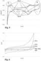
- 238000002484 cyclic voltammetry Methods 0.000 description 6
- 239000013067 intermediate product Substances 0.000 description 6
- 229910052700 potassium Inorganic materials 0.000 description 6
- 239000011591 potassium Substances 0.000 description 6
- 238000001075 voltammogram Methods 0.000 description 6
- 239000002253 acid Substances 0.000 description 5
- 239000011149 active material Substances 0.000 description 5
- 230000008859 change Effects 0.000 description 5
- 239000002131 composite material Substances 0.000 description 5
- 238000005137 deposition process Methods 0.000 description 5
- 150000002739 metals Chemical class 0.000 description 5
- 150000003891 oxalate salts Chemical class 0.000 description 5
- 230000001603 reducing effect Effects 0.000 description 5
- 238000005070 sampling Methods 0.000 description 5
- VYPSYNLAJGMNEJ-UHFFFAOYSA-N Silicium dioxide Chemical compound O=[Si]=O VYPSYNLAJGMNEJ-UHFFFAOYSA-N 0.000 description 4
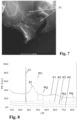
- 238000003917 TEM image Methods 0.000 description 4
- 238000010521 absorption reaction Methods 0.000 description 4
- 230000015572 biosynthetic process Effects 0.000 description 4
- 125000004432 carbon atom Chemical group C* 0.000 description 4
- 150000007942 carboxylates Chemical class 0.000 description 4
- SHZIWNPUGXLXDT-UHFFFAOYSA-N ethyl hexanoate Chemical compound CCCCCC(=O)OCC SHZIWNPUGXLXDT-UHFFFAOYSA-N 0.000 description 4
- 230000008595 infiltration Effects 0.000 description 4
- 238000001764 infiltration Methods 0.000 description 4
- 229910052742 iron Inorganic materials 0.000 description 4
- VNWKTOKETHGBQD-UHFFFAOYSA-N methane Chemical compound C VNWKTOKETHGBQD-UHFFFAOYSA-N 0.000 description 4
- 239000011049 pearl Substances 0.000 description 4
- 239000011164 primary particle Substances 0.000 description 4
- 230000009467 reduction Effects 0.000 description 4
- WEVYAHXRMPXWCK-UHFFFAOYSA-N Acetonitrile Chemical compound CC#N WEVYAHXRMPXWCK-UHFFFAOYSA-N 0.000 description 3
- 229920000049 Carbon (fiber) Polymers 0.000 description 3
- OKKJLVBELUTLKV-UHFFFAOYSA-N Methanol Chemical compound OC OKKJLVBELUTLKV-UHFFFAOYSA-N 0.000 description 3
- HEMHJVSKTPXQMS-UHFFFAOYSA-M Sodium hydroxide Chemical compound [OH-].[Na+] HEMHJVSKTPXQMS-UHFFFAOYSA-M 0.000 description 3
- 229910052804 chromium Inorganic materials 0.000 description 3
- 230000001186 cumulative effect Effects 0.000 description 3
- 229910021469 graphitizable carbon Inorganic materials 0.000 description 3
- 238000010438 heat treatment Methods 0.000 description 3
- 229930195733 hydrocarbon Natural products 0.000 description 3
- 150000002430 hydrocarbons Chemical class 0.000 description 3
- RAXXELZNTBOGNW-UHFFFAOYSA-N imidazole Natural products C1=CNC=N1 RAXXELZNTBOGNW-UHFFFAOYSA-N 0.000 description 3
- 229920000554 ionomer Polymers 0.000 description 3
- 229910052748 manganese Inorganic materials 0.000 description 3
- 239000000203 mixture Substances 0.000 description 3
- 229910052759 nickel Inorganic materials 0.000 description 3
- 150000002823 nitrates Chemical class 0.000 description 3
- 230000003647 oxidation Effects 0.000 description 3
- 238000007254 oxidation reaction Methods 0.000 description 3
- PIBWKRNGBLPSSY-UHFFFAOYSA-L palladium(II) chloride Chemical compound Cl[Pd]Cl PIBWKRNGBLPSSY-UHFFFAOYSA-L 0.000 description 3
- GPNDARIEYHPYAY-UHFFFAOYSA-N palladium(ii) nitrate Chemical compound [Pd+2].[O-][N+]([O-])=O.[O-][N+]([O-])=O GPNDARIEYHPYAY-UHFFFAOYSA-N 0.000 description 3
- 239000000047 product Substances 0.000 description 3
- 229910052703 rhodium Inorganic materials 0.000 description 3
- 239000010948 rhodium Substances 0.000 description 3
- 229910052707 ruthenium Inorganic materials 0.000 description 3
- 150000003839 salts Chemical class 0.000 description 3
- 239000011163 secondary particle Substances 0.000 description 3
- 238000003756 stirring Methods 0.000 description 3
- 239000000758 substrate Substances 0.000 description 3
- 239000000725 suspension Substances 0.000 description 3
- JBXWMZTZQQGLAG-UHFFFAOYSA-H tetrafluoroplatinum(2+) difluoride Chemical compound F[Pt](F)(F)(F)(F)F JBXWMZTZQQGLAG-UHFFFAOYSA-H 0.000 description 3
- VEJOYRPGKZZTJW-FDGPNNRMSA-N (z)-4-hydroxypent-3-en-2-one;platinum Chemical compound [Pt].C\C(O)=C\C(C)=O.C\C(O)=C\C(C)=O VEJOYRPGKZZTJW-FDGPNNRMSA-N 0.000 description 2
- MYRTYDVEIRVNKP-UHFFFAOYSA-N 1,2-Divinylbenzene Chemical compound C=CC1=CC=CC=C1C=C MYRTYDVEIRVNKP-UHFFFAOYSA-N 0.000 description 2
- HZAXFHJVJLSVMW-UHFFFAOYSA-N 2-Aminoethan-1-ol Chemical compound NCCO HZAXFHJVJLSVMW-UHFFFAOYSA-N 0.000 description 2
- IJGRMHOSHXDMSA-UHFFFAOYSA-N Atomic nitrogen Chemical compound N#N IJGRMHOSHXDMSA-UHFFFAOYSA-N 0.000 description 2
- BVKZGUZCCUSVTD-UHFFFAOYSA-M Bicarbonate Chemical compound OC([O-])=O BVKZGUZCCUSVTD-UHFFFAOYSA-M 0.000 description 2
- DHMQDGOQFOQNFH-UHFFFAOYSA-N Glycine Chemical compound NCC(O)=O DHMQDGOQFOQNFH-UHFFFAOYSA-N 0.000 description 2
- 229910003803 Gold(III) chloride Inorganic materials 0.000 description 2
- MHAJPDPJQMAIIY-UHFFFAOYSA-N Hydrogen peroxide Chemical compound OO MHAJPDPJQMAIIY-UHFFFAOYSA-N 0.000 description 2
- YNAVUWVOSKDBBP-UHFFFAOYSA-N Morpholine Chemical compound C1COCCN1 YNAVUWVOSKDBBP-UHFFFAOYSA-N 0.000 description 2
- 229910002651 NO3 Inorganic materials 0.000 description 2
- NHNBFGGVMKEFGY-UHFFFAOYSA-N Nitrate Chemical compound [O-][N+]([O-])=O NHNBFGGVMKEFGY-UHFFFAOYSA-N 0.000 description 2
- 238000001016 Ostwald ripening Methods 0.000 description 2
- GLUUGHFHXGJENI-UHFFFAOYSA-N Piperazine Chemical compound C1CNCCN1 GLUUGHFHXGJENI-UHFFFAOYSA-N 0.000 description 2
- NQRYJNQNLNOLGT-UHFFFAOYSA-N Piperidine Chemical compound C1CCNCC1 NQRYJNQNLNOLGT-UHFFFAOYSA-N 0.000 description 2
- JUJWROOIHBZHMG-UHFFFAOYSA-N Pyridine Chemical compound C1=CC=NC=C1 JUJWROOIHBZHMG-UHFFFAOYSA-N 0.000 description 2
- KAESVJOAVNADME-UHFFFAOYSA-N Pyrrole Chemical compound C=1C=CNC=1 KAESVJOAVNADME-UHFFFAOYSA-N 0.000 description 2
- DTQVDTLACAAQTR-UHFFFAOYSA-N Trifluoroacetic acid Chemical class OC(=O)C(F)(F)F DTQVDTLACAAQTR-UHFFFAOYSA-N 0.000 description 2
- 238000002441 X-ray diffraction Methods 0.000 description 2
- NTWWRCGRNVYWOU-UHFFFAOYSA-N [Pt].C(C)N Chemical compound [Pt].C(C)N NTWWRCGRNVYWOU-UHFFFAOYSA-N 0.000 description 2
- 150000001242 acetic acid derivatives Chemical class 0.000 description 2
- 229910052782 aluminium Inorganic materials 0.000 description 2
- 238000000137 annealing Methods 0.000 description 2
- 239000007864 aqueous solution Substances 0.000 description 2
- 238000001354 calcination Methods 0.000 description 2
- 238000004364 calculation method Methods 0.000 description 2
- 239000004917 carbon fiber Substances 0.000 description 2
- 239000012018 catalyst precursor Substances 0.000 description 2
- 238000006555 catalytic reaction Methods 0.000 description 2
- 239000007795 chemical reaction product Substances 0.000 description 2
- 238000001816 cooling Methods 0.000 description 2
- 229910052802 copper Inorganic materials 0.000 description 2
- 238000011161 development Methods 0.000 description 2
- 238000010586 diagram Methods 0.000 description 2
- 238000009792 diffusion process Methods 0.000 description 2
- 239000006185 dispersion Substances 0.000 description 2
- 238000001493 electron microscopy Methods 0.000 description 2
- 239000004088 foaming agent Substances 0.000 description 2
- 229910021397 glassy carbon Inorganic materials 0.000 description 2
- RJHLTVSLYWWTEF-UHFFFAOYSA-K gold trichloride Chemical compound Cl[Au](Cl)Cl RJHLTVSLYWWTEF-UHFFFAOYSA-K 0.000 description 2
- 239000011261 inert gas Substances 0.000 description 2
- 229910052741 iridium Inorganic materials 0.000 description 2
- 239000003446 ligand Substances 0.000 description 2
- 238000002156 mixing Methods 0.000 description 2
- 230000004048 modification Effects 0.000 description 2
- 238000012986 modification Methods 0.000 description 2
- 229910052750 molybdenum Inorganic materials 0.000 description 2
- 229910052758 niobium Inorganic materials 0.000 description 2
- 229910021470 non-graphitizable carbon Inorganic materials 0.000 description 2
- 239000003960 organic solvent Substances 0.000 description 2
- 229910052762 osmium Inorganic materials 0.000 description 2
- 235000006408 oxalic acid Nutrition 0.000 description 2
- PZKNFJIOIKQCPA-UHFFFAOYSA-N oxalic acid palladium Chemical compound [Pd].OC(=O)C(O)=O PZKNFJIOIKQCPA-UHFFFAOYSA-N 0.000 description 2
- 239000005518 polymer electrolyte Substances 0.000 description 2
- 239000010970 precious metal Substances 0.000 description 2
- 238000001878 scanning electron micrograph Methods 0.000 description 2
- 229910052711 selenium Inorganic materials 0.000 description 2
- 150000003377 silicon compounds Chemical class 0.000 description 2
- SQGYOTSLMSWVJD-UHFFFAOYSA-N silver(1+) nitrate Chemical compound [Ag+].[O-]N(=O)=O SQGYOTSLMSWVJD-UHFFFAOYSA-N 0.000 description 2
- 238000005245 sintering Methods 0.000 description 2
- 239000002904 solvent Substances 0.000 description 2
- 239000010421 standard material Substances 0.000 description 2
- BSGFBYZRPYAMRQ-UHFFFAOYSA-H tetrabromoplatinum(2+) dibromide Chemical compound Br[Pt](Br)(Br)(Br)(Br)Br BSGFBYZRPYAMRQ-UHFFFAOYSA-H 0.000 description 2
- 229910052718 tin Inorganic materials 0.000 description 2
- 239000010936 titanium Substances 0.000 description 2
- 229910052719 titanium Inorganic materials 0.000 description 2
- 229910052721 tungsten Inorganic materials 0.000 description 2
- 229910052720 vanadium Inorganic materials 0.000 description 2
- 229910052727 yttrium Inorganic materials 0.000 description 2
- 229910052725 zinc Inorganic materials 0.000 description 2
- IYWJIYWFPADQAN-LNTINUHCSA-N (z)-4-hydroxypent-3-en-2-one;ruthenium Chemical compound [Ru].C\C(O)=C\C(C)=O.C\C(O)=C\C(C)=O.C\C(O)=C\C(C)=O IYWJIYWFPADQAN-LNTINUHCSA-N 0.000 description 1
- KPZGRMZPZLOPBS-UHFFFAOYSA-N 1,3-dichloro-2,2-bis(chloromethyl)propane Chemical compound ClCC(CCl)(CCl)CCl KPZGRMZPZLOPBS-UHFFFAOYSA-N 0.000 description 1
- ZXSQEZNORDWBGZ-UHFFFAOYSA-N 1,3-dihydropyrrolo[2,3-b]pyridin-2-one Chemical compound C1=CN=C2NC(=O)CC2=C1 ZXSQEZNORDWBGZ-UHFFFAOYSA-N 0.000 description 1
- AKEXVWKYUAMNKL-UHFFFAOYSA-N 2,2-dimethylpropanoic acid;silver Chemical compound [Ag].CC(C)(C)C(O)=O AKEXVWKYUAMNKL-UHFFFAOYSA-N 0.000 description 1
- KXGFMDJXCMQABM-UHFFFAOYSA-N 2-methoxy-6-methylphenol Chemical compound [CH]OC1=CC=CC([CH])=C1O KXGFMDJXCMQABM-UHFFFAOYSA-N 0.000 description 1
- UIQPERPLCCTBGX-UHFFFAOYSA-N 2-phenylacetic acid;silver Chemical compound [Ag].OC(=O)CC1=CC=CC=C1 UIQPERPLCCTBGX-UHFFFAOYSA-N 0.000 description 1
- BKTGUZFRXMGVNI-UHFFFAOYSA-L 7,7-dimethyloctanoate platinum(2+) Chemical compound [Pt+2].CC(C)(C)CCCCCC([O-])=O.CC(C)(C)CCCCCC([O-])=O BKTGUZFRXMGVNI-UHFFFAOYSA-L 0.000 description 1
- QTBSBXVTEAMEQO-UHFFFAOYSA-M Acetate Chemical compound CC([O-])=O QTBSBXVTEAMEQO-UHFFFAOYSA-M 0.000 description 1
- NOWKCMXCCJGMRR-UHFFFAOYSA-N Aziridine Chemical compound C1CN1 NOWKCMXCCJGMRR-UHFFFAOYSA-N 0.000 description 1
- 238000004438 BET method Methods 0.000 description 1
- BTBUEUYNUDRHOZ-UHFFFAOYSA-N Borate Chemical compound [O-]B([O-])[O-] BTBUEUYNUDRHOZ-UHFFFAOYSA-N 0.000 description 1
- JIUDOXTUKCLRMU-UHFFFAOYSA-K C(C(C)C)(=O)O.C(C)(=O)O.[Au](O)(O)O Chemical compound C(C(C)C)(=O)O.C(C)(=O)O.[Au](O)(O)O JIUDOXTUKCLRMU-UHFFFAOYSA-K 0.000 description 1
- YOWXAOOFEIKMFU-UHFFFAOYSA-N C(C)(=O)OC1=C(C(=CC=C1)[N+](=O)[O-])[N+](=O)[O-].[Ag] Chemical compound C(C)(=O)OC1=C(C(=CC=C1)[N+](=O)[O-])[N+](=O)[O-].[Ag] YOWXAOOFEIKMFU-UHFFFAOYSA-N 0.000 description 1
- GPYJEAZMHPPOCL-UHFFFAOYSA-N C(C)(=O)OC1=C(C=CC=C1)[N+](=O)[O-].[Ag] Chemical compound C(C)(=O)OC1=C(C=CC=C1)[N+](=O)[O-].[Ag] GPYJEAZMHPPOCL-UHFFFAOYSA-N 0.000 description 1
- KXDHJXZQYSOELW-UHFFFAOYSA-N Carbamic acid Chemical class NC(O)=O KXDHJXZQYSOELW-UHFFFAOYSA-N 0.000 description 1
- 239000004215 Carbon black (E152) Substances 0.000 description 1
- VEXZGXHMUGYJMC-UHFFFAOYSA-M Chloride anion Chemical compound [Cl-] VEXZGXHMUGYJMC-UHFFFAOYSA-M 0.000 description 1
- RGHNJXZEOKUKBD-SQOUGZDYSA-M D-gluconate Chemical compound OC[C@@H](O)[C@@H](O)[C@H](O)[C@@H](O)C([O-])=O RGHNJXZEOKUKBD-SQOUGZDYSA-M 0.000 description 1
- MYMOFIZGZYHOMD-UHFFFAOYSA-N Dioxygen Chemical compound O=O MYMOFIZGZYHOMD-UHFFFAOYSA-N 0.000 description 1
- CWYNVVGOOAEACU-UHFFFAOYSA-N Fe2+ Chemical compound [Fe+2] CWYNVVGOOAEACU-UHFFFAOYSA-N 0.000 description 1
- BDAGIHXWWSANSR-UHFFFAOYSA-M Formate Chemical compound [O-]C=O BDAGIHXWWSANSR-UHFFFAOYSA-M 0.000 description 1
- 239000004471 Glycine Substances 0.000 description 1
- AEMRFAOFKBGASW-UHFFFAOYSA-N Glycolic acid Chemical class OCC(O)=O AEMRFAOFKBGASW-UHFFFAOYSA-N 0.000 description 1
- 229910002621 H2PtCl6 Inorganic materials 0.000 description 1
- 229910020427 K2PtCl4 Inorganic materials 0.000 description 1
- 229920000557 Nafion® Polymers 0.000 description 1
- 229910019142 PO4 Inorganic materials 0.000 description 1
- 239000004372 Polyvinyl alcohol Substances 0.000 description 1
- XBDQKXXYIPTUBI-UHFFFAOYSA-M Propionate Chemical compound CCC([O-])=O XBDQKXXYIPTUBI-UHFFFAOYSA-M 0.000 description 1
- XBDQKXXYIPTUBI-UHFFFAOYSA-N Propionic acid Chemical class CCC(O)=O XBDQKXXYIPTUBI-UHFFFAOYSA-N 0.000 description 1
- 229910001260 Pt alloy Inorganic materials 0.000 description 1
- 229910019029 PtCl4 Inorganic materials 0.000 description 1
- 229910021634 Rhenium(III) chloride Inorganic materials 0.000 description 1
- 229910021604 Rhodium(III) chloride Inorganic materials 0.000 description 1
- KJTLSVCANCCWHF-UHFFFAOYSA-N Ruthenium Chemical compound [Ru] KJTLSVCANCCWHF-UHFFFAOYSA-N 0.000 description 1
- 229910003902 SiCl 4 Inorganic materials 0.000 description 1
- 229910021607 Silver chloride Inorganic materials 0.000 description 1
- 229920002472 Starch Polymers 0.000 description 1
- GWEVSGVZZGPLCZ-UHFFFAOYSA-N Titan oxide Chemical compound O=[Ti]=O GWEVSGVZZGPLCZ-UHFFFAOYSA-N 0.000 description 1
- NRTOMJZYCJJWKI-UHFFFAOYSA-N Titanium nitride Chemical compound [Ti]#N NRTOMJZYCJJWKI-UHFFFAOYSA-N 0.000 description 1
- 239000007983 Tris buffer Substances 0.000 description 1
- KVJOVJBZNJUNMG-UHFFFAOYSA-R [NH4+].[NH4+].[NH4+].[NH4+].[O-][N+]([O-])=O.[O-][N+]([O-])=O.[O-][N+]([O-])=O.[O-][N+]([O-])=O Chemical compound [NH4+].[NH4+].[NH4+].[NH4+].[O-][N+]([O-])=O.[O-][N+]([O-])=O.[O-][N+]([O-])=O.[O-][N+]([O-])=O KVJOVJBZNJUNMG-UHFFFAOYSA-R 0.000 description 1
- NNVHNQYCOKZBMF-UHFFFAOYSA-L [Pt+2].[O-]Cl(=O)(=O)=O.[O-]Cl(=O)(=O)=O Chemical compound [Pt+2].[O-]Cl(=O)(=O)=O.[O-]Cl(=O)(=O)=O NNVHNQYCOKZBMF-UHFFFAOYSA-L 0.000 description 1
- 150000003869 acetamides Chemical class 0.000 description 1
- CTUFHBVSYAEMLM-UHFFFAOYSA-N acetic acid;platinum Chemical compound [Pt].CC(O)=O.CC(O)=O CTUFHBVSYAEMLM-UHFFFAOYSA-N 0.000 description 1
- 125000005595 acetylacetonate group Chemical group 0.000 description 1
- 239000000654 additive Substances 0.000 description 1
- 239000000443 aerosol Substances 0.000 description 1
- 230000001476 alcoholic effect Effects 0.000 description 1
- 125000001931 aliphatic group Chemical group 0.000 description 1
- 150000001336 alkenes Chemical class 0.000 description 1
- 150000004703 alkoxides Chemical class 0.000 description 1
- 150000001343 alkyl silanes Chemical class 0.000 description 1
- 238000005275 alloying Methods 0.000 description 1
- HSFWRNGVRCDJHI-UHFFFAOYSA-N alpha-acetylene Natural products C#C HSFWRNGVRCDJHI-UHFFFAOYSA-N 0.000 description 1
- 150000001408 amides Chemical class 0.000 description 1
- 150000001412 amines Chemical class 0.000 description 1
- 150000001413 amino acids Chemical class 0.000 description 1
- 150000001414 amino alcohols Chemical class 0.000 description 1
- 150000003863 ammonium salts Chemical class 0.000 description 1
- 238000004458 analytical method Methods 0.000 description 1
- 150000001450 anions Chemical class 0.000 description 1
- 229940045985 antineoplastic platinum compound Drugs 0.000 description 1
- 238000013459 approach Methods 0.000 description 1
- 239000012736 aqueous medium Substances 0.000 description 1
- 150000004945 aromatic hydrocarbons Chemical class 0.000 description 1
- 125000003118 aryl group Chemical group 0.000 description 1
- 238000000429 assembly Methods 0.000 description 1
- 230000000712 assembly Effects 0.000 description 1
- VSKCDODNDPOZKS-UHFFFAOYSA-L azane;platinum(2+);dihydroxide Chemical compound N.N.N.N.[OH-].[OH-].[Pt+2] VSKCDODNDPOZKS-UHFFFAOYSA-L 0.000 description 1
- UBTDQVRNDDEBSJ-UHFFFAOYSA-J azane;platinum(2+);tetrachloride Chemical compound N.N.N.N.[Cl-].[Cl-].[Cl-].[Cl-].[Pt+2].[Pt+2] UBTDQVRNDDEBSJ-UHFFFAOYSA-J 0.000 description 1
- PDJBCBKQQFANPW-UHFFFAOYSA-L azanide;platinum(2+);dichloride Chemical compound [NH2-].[NH2-].[NH2-].[NH2-].Cl[Pt]Cl PDJBCBKQQFANPW-UHFFFAOYSA-L 0.000 description 1
- 150000001540 azides Chemical class 0.000 description 1
- 239000003637 basic solution Substances 0.000 description 1
- 238000005452 bending Methods 0.000 description 1
- 230000008901 benefit Effects 0.000 description 1
- WPYMKLBDIGXBTP-UHFFFAOYSA-N benzoic acid Chemical compound OC(=O)C1=CC=CC=C1 WPYMKLBDIGXBTP-UHFFFAOYSA-N 0.000 description 1
- DSVRVHYFPPQFTI-UHFFFAOYSA-N bis(ethenyl)-methyl-trimethylsilyloxysilane;platinum Chemical compound [Pt].C[Si](C)(C)O[Si](C)(C=C)C=C DSVRVHYFPPQFTI-UHFFFAOYSA-N 0.000 description 1
- 150000001642 boronic acid derivatives Chemical class 0.000 description 1
- 239000006229 carbon black Substances 0.000 description 1
- 235000019241 carbon black Nutrition 0.000 description 1
- NQZFAUXPNWSLBI-UHFFFAOYSA-N carbon monoxide;ruthenium Chemical group [Ru].[Ru].[Ru].[O+]#[C-].[O+]#[C-].[O+]#[C-].[O+]#[C-].[O+]#[C-].[O+]#[C-].[O+]#[C-].[O+]#[C-].[O+]#[C-].[O+]#[C-].[O+]#[C-].[O+]#[C-] NQZFAUXPNWSLBI-UHFFFAOYSA-N 0.000 description 1
- BVKZGUZCCUSVTD-UHFFFAOYSA-N carbonic acid Chemical class OC(O)=O BVKZGUZCCUSVTD-UHFFFAOYSA-N 0.000 description 1
- 150000001728 carbonyl compounds Chemical class 0.000 description 1
- 125000003178 carboxy group Chemical group [H]OC(*)=O 0.000 description 1
- 230000015556 catabolic process Effects 0.000 description 1
- 150000001768 cations Chemical class 0.000 description 1
- 238000003889 chemical engineering Methods 0.000 description 1
- 150000001805 chlorine compounds Chemical class 0.000 description 1
- 150000001860 citric acid derivatives Chemical class 0.000 description 1
- 238000004140 cleaning Methods 0.000 description 1
- 230000001427 coherent effect Effects 0.000 description 1
- 239000011246 composite particle Substances 0.000 description 1
- 238000009833 condensation Methods 0.000 description 1
- 230000005494 condensation Effects 0.000 description 1
- 239000002322 conducting polymer Substances 0.000 description 1
- 229920001940 conductive polymer Polymers 0.000 description 1
- 229920001577 copolymer Polymers 0.000 description 1
- 239000011258 core-shell material Substances 0.000 description 1
- 125000004122 cyclic group Chemical group 0.000 description 1
- 238000006731 degradation reaction Methods 0.000 description 1
- 239000008367 deionised water Substances 0.000 description 1
- 229910021641 deionized water Inorganic materials 0.000 description 1
- 238000013461 design Methods 0.000 description 1
- 230000006866 deterioration Effects 0.000 description 1
- 150000004985 diamines Chemical class 0.000 description 1
- 238000004090 dissolution Methods 0.000 description 1
- 238000001035 drying Methods 0.000 description 1
- 239000010411 electrocatalyst Substances 0.000 description 1
- 238000005868 electrolysis reaction Methods 0.000 description 1
- SYQYELJXIDSVKA-UHFFFAOYSA-N ethyl butanoate;silver Chemical compound [Ag].CCCC(=O)OCC SYQYELJXIDSVKA-UHFFFAOYSA-N 0.000 description 1
- SSFLCKKTZYHWDL-UHFFFAOYSA-N ethyl hexanoate;gold;1h-imidazole Chemical compound [Au].C1=CNC=N1.CCCCCC(=O)OCC SSFLCKKTZYHWDL-UHFFFAOYSA-N 0.000 description 1
- OLPQABHDXGXNOL-UHFFFAOYSA-N ethyl hexanoate;silver Chemical compound [Ag].CCCCCC(=O)OCC OLPQABHDXGXNOL-UHFFFAOYSA-N 0.000 description 1
- 125000002534 ethynyl group Chemical group [H]C#C* 0.000 description 1
- 239000004744 fabric Substances 0.000 description 1
- 230000002349 favourable effect Effects 0.000 description 1
- 238000001914 filtration Methods 0.000 description 1
- BABIQFTUTNDWMB-UHFFFAOYSA-M fluorosilver;hydrofluoride Chemical compound F.[Ag]F BABIQFTUTNDWMB-UHFFFAOYSA-M 0.000 description 1
- 150000003948 formamides Chemical class 0.000 description 1
- 150000004675 formic acid derivatives Chemical class 0.000 description 1
- QVGWNAZAMFWLPE-UHFFFAOYSA-K gold(3+) 3-oxobutanoate Chemical compound [Au+3].CC(=O)CC([O-])=O.CC(=O)CC([O-])=O.CC(=O)CC([O-])=O QVGWNAZAMFWLPE-UHFFFAOYSA-K 0.000 description 1
- BBEULCUFCNVALG-UHFFFAOYSA-N gold(3+) triazide Chemical compound [Au+3].[N-]=[N+]=[N-].[N-]=[N+]=[N-].[N-]=[N+]=[N-] BBEULCUFCNVALG-UHFFFAOYSA-N 0.000 description 1
- OTCKNHQTLOBDDD-UHFFFAOYSA-K gold(3+);triacetate Chemical compound [Au+3].CC([O-])=O.CC([O-])=O.CC([O-])=O OTCKNHQTLOBDDD-UHFFFAOYSA-K 0.000 description 1
- MXZVHYUSLJAVOE-UHFFFAOYSA-N gold(3+);tricyanide Chemical compound [Au+3].N#[C-].N#[C-].N#[C-] MXZVHYUSLJAVOE-UHFFFAOYSA-N 0.000 description 1
- 239000008187 granular material Substances 0.000 description 1
- 238000005469 granulation Methods 0.000 description 1
- 230000003179 granulation Effects 0.000 description 1
- 238000000227 grinding Methods 0.000 description 1
- 150000004820 halides Chemical class 0.000 description 1
- 125000005843 halogen group Chemical class 0.000 description 1
- 239000007970 homogeneous dispersion Substances 0.000 description 1
- 238000005984 hydrogenation reaction Methods 0.000 description 1
- 150000004679 hydroxides Chemical class 0.000 description 1
- 238000005470 impregnation Methods 0.000 description 1
- 150000002475 indoles Chemical class 0.000 description 1
- 229910010272 inorganic material Inorganic materials 0.000 description 1
- 239000011147 inorganic material Substances 0.000 description 1
- 230000037427 ion transport Effects 0.000 description 1
- 150000002500 ions Chemical class 0.000 description 1
- MILUBEOXRNEUHS-UHFFFAOYSA-N iridium(3+) Chemical compound [Ir+3] MILUBEOXRNEUHS-UHFFFAOYSA-N 0.000 description 1
- 230000007774 longterm Effects 0.000 description 1
- 239000011302 mesophase pitch Substances 0.000 description 1
- 239000000178 monomer Substances 0.000 description 1
- 210000003739 neck Anatomy 0.000 description 1
- 150000002825 nitriles Chemical class 0.000 description 1
- 150000002826 nitrites Chemical class 0.000 description 1
- 229910052757 nitrogen Inorganic materials 0.000 description 1
- 239000012299 nitrogen atmosphere Substances 0.000 description 1
- QIQXTHQIDYTFRH-UHFFFAOYSA-N octadecanoic acid Chemical compound CCCCCCCCCCCCCCCCCC(O)=O QIQXTHQIDYTFRH-UHFFFAOYSA-N 0.000 description 1
- WWZKQHOCKIZLMA-UHFFFAOYSA-M octanoate Chemical compound CCCCCCCC([O-])=O WWZKQHOCKIZLMA-UHFFFAOYSA-M 0.000 description 1
- JRZJOMJEPLMPRA-UHFFFAOYSA-N olefin Natural products CCCCCCCC=C JRZJOMJEPLMPRA-UHFFFAOYSA-N 0.000 description 1
- 150000002894 organic compounds Chemical class 0.000 description 1
- GEVPUGOOGXGPIO-UHFFFAOYSA-N oxalic acid;dihydrate Chemical compound O.O.OC(=O)C(O)=O GEVPUGOOGXGPIO-UHFFFAOYSA-N 0.000 description 1
- 239000007800 oxidant agent Substances 0.000 description 1
- 238000006864 oxidative decomposition reaction Methods 0.000 description 1
- OTCVAHKKMMUFAY-UHFFFAOYSA-N oxosilver Chemical class [Ag]=O OTCVAHKKMMUFAY-UHFFFAOYSA-N 0.000 description 1
- MUJIDPITZJWBSW-UHFFFAOYSA-N palladium(2+) Chemical compound [Pd+2] MUJIDPITZJWBSW-UHFFFAOYSA-N 0.000 description 1
- PBDBXAQKXCXZCJ-UHFFFAOYSA-L palladium(2+);2,2,2-trifluoroacetate Chemical compound [Pd+2].[O-]C(=O)C(F)(F)F.[O-]C(=O)C(F)(F)F PBDBXAQKXCXZCJ-UHFFFAOYSA-L 0.000 description 1
- APGNMHZUERWZME-UHFFFAOYSA-L palladium(2+);3,3,5,5-tetramethylhexanoate Chemical compound [Pd+2].CC(C)(C)CC(C)(C)CC([O-])=O.CC(C)(C)CC(C)(C)CC([O-])=O APGNMHZUERWZME-UHFFFAOYSA-L 0.000 description 1
- ZVSLRJWQDNRUDU-UHFFFAOYSA-L palladium(2+);propanoate Chemical compound [Pd+2].CCC([O-])=O.CCC([O-])=O ZVSLRJWQDNRUDU-UHFFFAOYSA-L 0.000 description 1
- RFLFDJSIZCCYIP-UHFFFAOYSA-L palladium(2+);sulfate Chemical compound [Pd+2].[O-]S([O-])(=O)=O RFLFDJSIZCCYIP-UHFFFAOYSA-L 0.000 description 1
- 229910000364 palladium(II) sulfate Inorganic materials 0.000 description 1
- YJVFFLUZDVXJQI-UHFFFAOYSA-L palladium(ii) acetate Chemical compound [Pd+2].CC([O-])=O.CC([O-])=O YJVFFLUZDVXJQI-UHFFFAOYSA-L 0.000 description 1
- ZZSIDSMUTXFKNS-UHFFFAOYSA-N perylene red Chemical compound CC(C)C1=CC=CC(C(C)C)=C1N(C(=O)C=1C2=C3C4=C(OC=5C=CC=CC=5)C=1)C(=O)C2=CC(OC=1C=CC=CC=1)=C3C(C(OC=1C=CC=CC=1)=CC1=C2C(C(N(C=3C(=CC=CC=3C(C)C)C(C)C)C1=O)=O)=C1)=C2C4=C1OC1=CC=CC=C1 ZZSIDSMUTXFKNS-UHFFFAOYSA-N 0.000 description 1
- 239000005011 phenolic resin Substances 0.000 description 1
- 229920001568 phenolic resin Polymers 0.000 description 1
- 235000021317 phosphate Nutrition 0.000 description 1
- 150000003013 phosphoric acid derivatives Chemical class 0.000 description 1
- HRGDZIGMBDGFTC-UHFFFAOYSA-N platinum(2+) Chemical class [Pt+2] HRGDZIGMBDGFTC-UHFFFAOYSA-N 0.000 description 1
- HHNGEOJZFQTKKI-UHFFFAOYSA-L platinum(2+);carbonate Chemical compound [Pt+2].[O-]C([O-])=O HHNGEOJZFQTKKI-UHFFFAOYSA-L 0.000 description 1
- PJSXONYYFHKZEU-UHFFFAOYSA-L platinum(2+);dibenzoate Chemical compound [Pt+2].[O-]C(=O)C1=CC=CC=C1.[O-]C(=O)C1=CC=CC=C1 PJSXONYYFHKZEU-UHFFFAOYSA-L 0.000 description 1
- BAYHTBIRMBUKHX-UHFFFAOYSA-L platinum(2+);diformate Chemical compound [Pt+2].[O-]C=O.[O-]C=O BAYHTBIRMBUKHX-UHFFFAOYSA-L 0.000 description 1
- NFOHLBHARAZXFQ-UHFFFAOYSA-L platinum(2+);dihydroxide Chemical compound O[Pt]O NFOHLBHARAZXFQ-UHFFFAOYSA-L 0.000 description 1
- NWAHZABTSDUXMJ-UHFFFAOYSA-N platinum(2+);dinitrate Chemical compound [Pt+2].[O-][N+]([O-])=O.[O-][N+]([O-])=O NWAHZABTSDUXMJ-UHFFFAOYSA-N 0.000 description 1
- YNGCBAQTERUCJP-UHFFFAOYSA-L platinum(2+);propanoate Chemical compound [Pt+2].CCC([O-])=O.CCC([O-])=O YNGCBAQTERUCJP-UHFFFAOYSA-L 0.000 description 1
- PQTLYDQECILMMB-UHFFFAOYSA-L platinum(2+);sulfate Chemical compound [Pt+2].[O-]S([O-])(=O)=O PQTLYDQECILMMB-UHFFFAOYSA-L 0.000 description 1
- AAIMUHANAAXZIF-UHFFFAOYSA-L platinum(2+);sulfite Chemical compound [Pt+2].[O-]S([O-])=O AAIMUHANAAXZIF-UHFFFAOYSA-L 0.000 description 1
- 229920000642 polymer Polymers 0.000 description 1
- 239000004810 polytetrafluoroethylene Substances 0.000 description 1
- 229920001343 polytetrafluoroethylene Polymers 0.000 description 1
- 229920002451 polyvinyl alcohol Polymers 0.000 description 1
- 159000000001 potassium salts Chemical class 0.000 description 1
- 230000001376 precipitating effect Effects 0.000 description 1
- 238000003825 pressing Methods 0.000 description 1
- ZNZJJSYHZBXQSM-UHFFFAOYSA-N propane-2,2-diamine Chemical compound CC(C)(N)N ZNZJJSYHZBXQSM-UHFFFAOYSA-N 0.000 description 1
- 238000000746 purification Methods 0.000 description 1
- UMJSCPRVCHMLSP-UHFFFAOYSA-N pyridine Natural products COC1=CC=CN=C1 UMJSCPRVCHMLSP-UHFFFAOYSA-N 0.000 description 1
- 239000002994 raw material Substances 0.000 description 1
- 230000009257 reactivity Effects 0.000 description 1
- 229910052702 rhenium Inorganic materials 0.000 description 1
- HYERJXDYFLQTGF-UHFFFAOYSA-N rhenium Chemical compound [Re][Re][Re][Re][Re][Re][Re][Re][Re][Re][Re][Re][Re][Re][Re][Re][Re][Re][Re][Re][Re][Re][Re][Re][Re][Re][Re][Re][Re][Re][Re][Re][Re][Re][Re][Re][Re][Re][Re][Re][Re][Re][Re][Re][Re][Re][Re][Re][Re][Re][Re][Re][Re][Re][Re][Re][Re][Re][Re][Re][Re][Re][Re][Re][Re][Re][Re][Re] HYERJXDYFLQTGF-UHFFFAOYSA-N 0.000 description 1
- MHOVAHRLVXNVSD-UHFFFAOYSA-N rhodium atom Chemical compound [Rh] MHOVAHRLVXNVSD-UHFFFAOYSA-N 0.000 description 1
- VXNYVYJABGOSBX-UHFFFAOYSA-N rhodium(3+);trinitrate Chemical compound [Rh+3].[O-][N+]([O-])=O.[O-][N+]([O-])=O.[O-][N+]([O-])=O VXNYVYJABGOSBX-UHFFFAOYSA-N 0.000 description 1
- SONJTKJMTWTJCT-UHFFFAOYSA-K rhodium(iii) chloride Chemical compound [Cl-].[Cl-].[Cl-].[Rh+3] SONJTKJMTWTJCT-UHFFFAOYSA-K 0.000 description 1
- 230000000630 rising effect Effects 0.000 description 1
- LECPYKYNIWHZFT-UHFFFAOYSA-K ruthenium(3+) triperchlorate Chemical compound [Ru+3].[O-]Cl(=O)(=O)=O.[O-]Cl(=O)(=O)=O.[O-]Cl(=O)(=O)=O LECPYKYNIWHZFT-UHFFFAOYSA-K 0.000 description 1
- OJLCQGGSMYKWEK-UHFFFAOYSA-K ruthenium(3+);triacetate Chemical compound [Ru+3].CC([O-])=O.CC([O-])=O.CC([O-])=O OJLCQGGSMYKWEK-UHFFFAOYSA-K 0.000 description 1
- YBCAZPLXEGKKFM-UHFFFAOYSA-K ruthenium(iii) chloride Chemical compound [Cl-].[Cl-].[Cl-].[Ru+3] YBCAZPLXEGKKFM-UHFFFAOYSA-K 0.000 description 1
- 229920006395 saturated elastomer Polymers 0.000 description 1
- NBYLLBXLDOPANK-UHFFFAOYSA-M silver 2-carboxyphenolate hydrate Chemical compound C1=CC=C(C(=C1)C(=O)O)[O-].O.[Ag+] NBYLLBXLDOPANK-UHFFFAOYSA-M 0.000 description 1
- CQLFBEKRDQMJLZ-UHFFFAOYSA-M silver acetate Chemical compound [Ag+].CC([O-])=O CQLFBEKRDQMJLZ-UHFFFAOYSA-M 0.000 description 1
- 229940071536 silver acetate Drugs 0.000 description 1
- QBFXQJXHEPIJKW-UHFFFAOYSA-N silver azide Chemical compound [Ag+].[N-]=[N+]=[N-] QBFXQJXHEPIJKW-UHFFFAOYSA-N 0.000 description 1
- 229910001958 silver carbonate Inorganic materials 0.000 description 1
- LKZMBDSASOBTPN-UHFFFAOYSA-L silver carbonate Substances [Ag].[O-]C([O-])=O LKZMBDSASOBTPN-UHFFFAOYSA-L 0.000 description 1
- 229940071575 silver citrate Drugs 0.000 description 1
- 229940096017 silver fluoride Drugs 0.000 description 1
- HKZLPVFGJNLROG-UHFFFAOYSA-M silver monochloride Chemical compound [Cl-].[Ag+] HKZLPVFGJNLROG-UHFFFAOYSA-M 0.000 description 1
- REYHXKZHIMGNSE-UHFFFAOYSA-M silver monofluoride Chemical compound [F-].[Ag+] REYHXKZHIMGNSE-UHFFFAOYSA-M 0.000 description 1
- 229910001961 silver nitrate Inorganic materials 0.000 description 1
- KKKDGYXNGYJJRX-UHFFFAOYSA-M silver nitrite Chemical compound [Ag+].[O-]N=O KKKDGYXNGYJJRX-UHFFFAOYSA-M 0.000 description 1
- XNGYKPINNDWGGF-UHFFFAOYSA-L silver oxalate Chemical compound [Ag+].[Ag+].[O-]C(=O)C([O-])=O XNGYKPINNDWGGF-UHFFFAOYSA-L 0.000 description 1
- 229910001923 silver oxide Inorganic materials 0.000 description 1
- 229910001494 silver tetrafluoroborate Inorganic materials 0.000 description 1
- QRUBYZBWAOOHSV-UHFFFAOYSA-M silver trifluoromethanesulfonate Chemical compound [Ag+].[O-]S(=O)(=O)C(F)(F)F QRUBYZBWAOOHSV-UHFFFAOYSA-M 0.000 description 1
- CHACQUSVOVNARW-LNKPDPKZSA-M silver;(z)-4-oxopent-2-en-2-olate Chemical compound [Ag+].C\C([O-])=C\C(C)=O CHACQUSVOVNARW-LNKPDPKZSA-M 0.000 description 1
- ILJKPORWEQMDAC-UHFFFAOYSA-N silver;2,2,2-trichloroacetic acid Chemical compound [Ag].OC(=O)C(Cl)(Cl)Cl ILJKPORWEQMDAC-UHFFFAOYSA-N 0.000 description 1
- KZJPVUDYAMEDRM-UHFFFAOYSA-M silver;2,2,2-trifluoroacetate Chemical compound [Ag+].[O-]C(=O)C(F)(F)F KZJPVUDYAMEDRM-UHFFFAOYSA-M 0.000 description 1
- XAYJXAUUXJTOSI-UHFFFAOYSA-M silver;2,2,3,3,3-pentafluoropropanoate Chemical compound [Ag+].[O-]C(=O)C(F)(F)C(F)(F)F XAYJXAUUXJTOSI-UHFFFAOYSA-M 0.000 description 1
- GPNIJXACCBKBEP-UHFFFAOYSA-M silver;2,2,3,3,4,4,4-heptafluorobutanoate Chemical compound [Ag+].[O-]C(=O)C(F)(F)C(F)(F)C(F)(F)F GPNIJXACCBKBEP-UHFFFAOYSA-M 0.000 description 1
- IZSBQHHWLRIJIB-UHFFFAOYSA-M silver;2-fluoro-5-nitrobenzoate Chemical compound [Ag+].[O-]C(=O)C1=CC([N+]([O-])=O)=CC=C1F IZSBQHHWLRIJIB-UHFFFAOYSA-M 0.000 description 1
- RUJQWQMCBPWFDO-UHFFFAOYSA-M silver;2-hydroxyacetate Chemical compound [Ag+].OCC([O-])=O RUJQWQMCBPWFDO-UHFFFAOYSA-M 0.000 description 1
- LMEWRZSPCQHBOB-UHFFFAOYSA-M silver;2-hydroxypropanoate Chemical compound [Ag+].CC(O)C([O-])=O LMEWRZSPCQHBOB-UHFFFAOYSA-M 0.000 description 1
- CBBVZDBEHVFMHE-UHFFFAOYSA-M silver;4-cyclohexylbutanoate Chemical compound [Ag+].[O-]C(=O)CCCC1CCCCC1 CBBVZDBEHVFMHE-UHFFFAOYSA-M 0.000 description 1
- JUDUFOKGIZUSFP-UHFFFAOYSA-M silver;4-methylbenzenesulfonate Chemical compound [Ag+].CC1=CC=C(S([O-])(=O)=O)C=C1 JUDUFOKGIZUSFP-UHFFFAOYSA-M 0.000 description 1
- RQZVTOHLJOBKCW-UHFFFAOYSA-M silver;7,7-dimethyloctanoate Chemical compound [Ag+].CC(C)(C)CCCCCC([O-])=O RQZVTOHLJOBKCW-UHFFFAOYSA-M 0.000 description 1
- CLDWGXZGFUNWKB-UHFFFAOYSA-M silver;benzoate Chemical compound [Ag+].[O-]C(=O)C1=CC=CC=C1 CLDWGXZGFUNWKB-UHFFFAOYSA-M 0.000 description 1
- JKOCEVIXVMBKJA-UHFFFAOYSA-M silver;butanoate Chemical compound [Ag+].CCCC([O-])=O JKOCEVIXVMBKJA-UHFFFAOYSA-M 0.000 description 1
- YZQHCDOJNFUGQF-UHFFFAOYSA-N silver;cyclopenta-1,3-diene Chemical class [Ag+].C=1C=C[CH-]C=1 YZQHCDOJNFUGQF-UHFFFAOYSA-N 0.000 description 1
- OIZSSBDNMBMYFL-UHFFFAOYSA-M silver;decanoate Chemical compound [Ag+].CCCCCCCCCC([O-])=O OIZSSBDNMBMYFL-UHFFFAOYSA-M 0.000 description 1
- CYLMOXYXYHNGHZ-UHFFFAOYSA-M silver;propanoate Chemical compound [Ag+].CCC([O-])=O CYLMOXYXYHNGHZ-UHFFFAOYSA-M 0.000 description 1
- 238000003980 solgel method Methods 0.000 description 1
- 239000007787 solid Substances 0.000 description 1
- 238000001228 spectrum Methods 0.000 description 1
- 230000006641 stabilisation Effects 0.000 description 1
- 238000011105 stabilization Methods 0.000 description 1
- 239000008107 starch Substances 0.000 description 1
- 235000019698 starch Nutrition 0.000 description 1
- 150000003871 sulfonates Chemical class 0.000 description 1
- 125000000542 sulfonic acid group Chemical group 0.000 description 1
- 230000008961 swelling Effects 0.000 description 1
- 238000003786 synthesis reaction Methods 0.000 description 1
- 229920002994 synthetic fiber Polymers 0.000 description 1
- 238000005496 tempering Methods 0.000 description 1
- FBEIPJNQGITEBL-UHFFFAOYSA-J tetrachloroplatinum Chemical compound Cl[Pt](Cl)(Cl)Cl FBEIPJNQGITEBL-UHFFFAOYSA-J 0.000 description 1
- BFKJFAAPBSQJPD-UHFFFAOYSA-N tetrafluoroethene Chemical group FC(F)=C(F)F BFKJFAAPBSQJPD-UHFFFAOYSA-N 0.000 description 1
- XOLBLPGZBRYERU-UHFFFAOYSA-N tin dioxide Chemical compound O=[Sn]=O XOLBLPGZBRYERU-UHFFFAOYSA-N 0.000 description 1
- 229910001887 tin oxide Inorganic materials 0.000 description 1
- OGIDPMRJRNCKJF-UHFFFAOYSA-N titanium oxide Inorganic materials [Ti]=O OGIDPMRJRNCKJF-UHFFFAOYSA-N 0.000 description 1
- 150000003852 triazoles Chemical class 0.000 description 1
- LOIHSHVELSAXQN-UHFFFAOYSA-K trirhenium nonachloride Chemical compound Cl[Re](Cl)Cl LOIHSHVELSAXQN-UHFFFAOYSA-K 0.000 description 1
- ZRAOLHHYMQLCAW-UHFFFAOYSA-N tris(1h-pyrazol-5-yl) borate Chemical compound C1=CNN=C1OB(OC1=NNC=C1)OC=1C=CNN=1 ZRAOLHHYMQLCAW-UHFFFAOYSA-N 0.000 description 1
- QUTYHQJYVDNJJA-UHFFFAOYSA-K trisilver;2-hydroxypropane-1,2,3-tricarboxylate Chemical compound [Ag+].[Ag+].[Ag+].[O-]C(=O)CC(O)(CC([O-])=O)C([O-])=O QUTYHQJYVDNJJA-UHFFFAOYSA-K 0.000 description 1
- 230000007306 turnover Effects 0.000 description 1
- 238000012982 x-ray structure analysis Methods 0.000 description 1
Images


Classifications
-
- B—PERFORMING OPERATIONS; TRANSPORTING
- B01—PHYSICAL OR CHEMICAL PROCESSES OR APPARATUS IN GENERAL
- B01J—CHEMICAL OR PHYSICAL PROCESSES, e.g. CATALYSIS OR COLLOID CHEMISTRY; THEIR RELEVANT APPARATUS
- B01J23/00—Catalysts comprising metals or metal oxides or hydroxides, not provided for in group B01J21/00
- B01J23/38—Catalysts comprising metals or metal oxides or hydroxides, not provided for in group B01J21/00 of noble metals
-
- B—PERFORMING OPERATIONS; TRANSPORTING
- B01—PHYSICAL OR CHEMICAL PROCESSES OR APPARATUS IN GENERAL
- B01J—CHEMICAL OR PHYSICAL PROCESSES, e.g. CATALYSIS OR COLLOID CHEMISTRY; THEIR RELEVANT APPARATUS
- B01J37/00—Processes, in general, for preparing catalysts; Processes, in general, for activation of catalysts
- B01J37/06—Washing
-
- C—CHEMISTRY; METALLURGY
- C01—INORGANIC CHEMISTRY
- C01B—NON-METALLIC ELEMENTS; COMPOUNDS THEREOF; METALLOIDS OR COMPOUNDS THEREOF NOT COVERED BY SUBCLASS C01C
- C01B32/00—Carbon; Compounds thereof
- C01B32/20—Graphite
-
- B—PERFORMING OPERATIONS; TRANSPORTING
- B01—PHYSICAL OR CHEMICAL PROCESSES OR APPARATUS IN GENERAL
- B01J—CHEMICAL OR PHYSICAL PROCESSES, e.g. CATALYSIS OR COLLOID CHEMISTRY; THEIR RELEVANT APPARATUS
- B01J23/00—Catalysts comprising metals or metal oxides or hydroxides, not provided for in group B01J21/00
- B01J23/38—Catalysts comprising metals or metal oxides or hydroxides, not provided for in group B01J21/00 of noble metals
- B01J23/40—Catalysts comprising metals or metal oxides or hydroxides, not provided for in group B01J21/00 of noble metals of the platinum group metals
- B01J23/42—Platinum
-
- B—PERFORMING OPERATIONS; TRANSPORTING
- B01—PHYSICAL OR CHEMICAL PROCESSES OR APPARATUS IN GENERAL
- B01J—CHEMICAL OR PHYSICAL PROCESSES, e.g. CATALYSIS OR COLLOID CHEMISTRY; THEIR RELEVANT APPARATUS
- B01J37/00—Processes, in general, for preparing catalysts; Processes, in general, for activation of catalysts
- B01J37/0009—Use of binding agents; Moulding; Pressing; Powdering; Granulating; Addition of materials ameliorating the mechanical properties of the product catalyst
- B01J37/0018—Addition of a binding agent or of material, later completely removed among others as result of heat treatment, leaching or washing,(e.g. forming of pores; protective layer, desintegrating by heat)
-
- B—PERFORMING OPERATIONS; TRANSPORTING
- B01—PHYSICAL OR CHEMICAL PROCESSES OR APPARATUS IN GENERAL
- B01J—CHEMICAL OR PHYSICAL PROCESSES, e.g. CATALYSIS OR COLLOID CHEMISTRY; THEIR RELEVANT APPARATUS
- B01J37/00—Processes, in general, for preparing catalysts; Processes, in general, for activation of catalysts
- B01J37/08—Heat treatment
- B01J37/082—Decomposition and pyrolysis
- B01J37/084—Decomposition of carbon-containing compounds into carbon
-
- B—PERFORMING OPERATIONS; TRANSPORTING
- B01—PHYSICAL OR CHEMICAL PROCESSES OR APPARATUS IN GENERAL
- B01J—CHEMICAL OR PHYSICAL PROCESSES, e.g. CATALYSIS OR COLLOID CHEMISTRY; THEIR RELEVANT APPARATUS
- B01J37/00—Processes, in general, for preparing catalysts; Processes, in general, for activation of catalysts
- B01J37/12—Oxidising
- B01J37/14—Oxidising with gases containing free oxygen
-
- C—CHEMISTRY; METALLURGY
- C01—INORGANIC CHEMISTRY
- C01B—NON-METALLIC ELEMENTS; COMPOUNDS THEREOF; METALLOIDS OR COMPOUNDS THEREOF NOT COVERED BY SUBCLASS C01C
- C01B32/00—Carbon; Compounds thereof
- C01B32/05—Preparation or purification of carbon not covered by groups C01B32/15, C01B32/20, C01B32/25, C01B32/30
-
- C—CHEMISTRY; METALLURGY
- C01—INORGANIC CHEMISTRY
- C01B—NON-METALLIC ELEMENTS; COMPOUNDS THEREOF; METALLOIDS OR COMPOUNDS THEREOF NOT COVERED BY SUBCLASS C01C
- C01B32/00—Carbon; Compounds thereof
- C01B32/20—Graphite
- C01B32/205—Preparation
-
- C—CHEMISTRY; METALLURGY
- C01—INORGANIC CHEMISTRY
- C01B—NON-METALLIC ELEMENTS; COMPOUNDS THEREOF; METALLOIDS OR COMPOUNDS THEREOF NOT COVERED BY SUBCLASS C01C
- C01B32/00—Carbon; Compounds thereof
- C01B32/20—Graphite
- C01B32/21—After-treatment
-
- H—ELECTRICITY
- H01—ELECTRIC ELEMENTS
- H01M—PROCESSES OR MEANS, e.g. BATTERIES, FOR THE DIRECT CONVERSION OF CHEMICAL ENERGY INTO ELECTRICAL ENERGY
- H01M4/00—Electrodes
- H01M4/86—Inert electrodes with catalytic activity, e.g. for fuel cells
- H01M4/8605—Porous electrodes
-
- H—ELECTRICITY
- H01—ELECTRIC ELEMENTS
- H01M—PROCESSES OR MEANS, e.g. BATTERIES, FOR THE DIRECT CONVERSION OF CHEMICAL ENERGY INTO ELECTRICAL ENERGY
- H01M4/00—Electrodes
- H01M4/86—Inert electrodes with catalytic activity, e.g. for fuel cells
- H01M4/88—Processes of manufacture
- H01M4/8817—Treatment of supports before application of the catalytic active composition
-
- H—ELECTRICITY
- H01—ELECTRIC ELEMENTS
- H01M—PROCESSES OR MEANS, e.g. BATTERIES, FOR THE DIRECT CONVERSION OF CHEMICAL ENERGY INTO ELECTRICAL ENERGY
- H01M4/00—Electrodes
- H01M4/86—Inert electrodes with catalytic activity, e.g. for fuel cells
- H01M4/88—Processes of manufacture
- H01M4/8825—Methods for deposition of the catalytic active composition
- H01M4/8842—Coating using a catalyst salt precursor in solution followed by evaporation and reduction of the precursor
-
- H—ELECTRICITY
- H01—ELECTRIC ELEMENTS
- H01M—PROCESSES OR MEANS, e.g. BATTERIES, FOR THE DIRECT CONVERSION OF CHEMICAL ENERGY INTO ELECTRICAL ENERGY
- H01M4/00—Electrodes
- H01M4/86—Inert electrodes with catalytic activity, e.g. for fuel cells
- H01M4/90—Selection of catalytic material
- H01M4/92—Metals of platinum group
- H01M4/925—Metals of platinum group supported on carriers, e.g. powder carriers
- H01M4/926—Metals of platinum group supported on carriers, e.g. powder carriers on carbon or graphite
-
- B01J35/393—
-
- B01J35/613—
-
- B01J35/615—
-
- B01J35/638—
-
- B01J35/653—
-
- B01J35/657—
-
- B01J35/66—
-
- B01J35/695—
-
- B—PERFORMING OPERATIONS; TRANSPORTING
- B01—PHYSICAL OR CHEMICAL PROCESSES OR APPARATUS IN GENERAL
- B01J—CHEMICAL OR PHYSICAL PROCESSES, e.g. CATALYSIS OR COLLOID CHEMISTRY; THEIR RELEVANT APPARATUS
- B01J37/00—Processes, in general, for preparing catalysts; Processes, in general, for activation of catalysts
- B01J37/02—Impregnation, coating or precipitation
- B01J37/0201—Impregnation
- B01J37/0203—Impregnation the impregnation liquid containing organic compounds
-
- H—ELECTRICITY
- H01—ELECTRIC ELEMENTS
- H01M—PROCESSES OR MEANS, e.g. BATTERIES, FOR THE DIRECT CONVERSION OF CHEMICAL ENERGY INTO ELECTRICAL ENERGY
- H01M8/00—Fuel cells; Manufacture thereof
- H01M8/10—Fuel cells with solid electrolytes
- H01M2008/1095—Fuel cells with polymeric electrolytes
-
- H—ELECTRICITY
- H01—ELECTRIC ELEMENTS
- H01M—PROCESSES OR MEANS, e.g. BATTERIES, FOR THE DIRECT CONVERSION OF CHEMICAL ENERGY INTO ELECTRICAL ENERGY
- H01M2250/00—Fuel cells for particular applications; Specific features of fuel cell system
- H01M2250/20—Fuel cells in motive systems, e.g. vehicle, ship, plane
-
- Y—GENERAL TAGGING OF NEW TECHNOLOGICAL DEVELOPMENTS; GENERAL TAGGING OF CROSS-SECTIONAL TECHNOLOGIES SPANNING OVER SEVERAL SECTIONS OF THE IPC; TECHNICAL SUBJECTS COVERED BY FORMER USPC CROSS-REFERENCE ART COLLECTIONS [XRACs] AND DIGESTS
- Y02—TECHNOLOGIES OR APPLICATIONS FOR MITIGATION OR ADAPTATION AGAINST CLIMATE CHANGE
- Y02E—REDUCTION OF GREENHOUSE GAS [GHG] EMISSIONS, RELATED TO ENERGY GENERATION, TRANSMISSION OR DISTRIBUTION
- Y02E60/00—Enabling technologies; Technologies with a potential or indirect contribution to GHG emissions mitigation
- Y02E60/30—Hydrogen technology
- Y02E60/50—Fuel cells
-
- Y—GENERAL TAGGING OF NEW TECHNOLOGICAL DEVELOPMENTS; GENERAL TAGGING OF CROSS-SECTIONAL TECHNOLOGIES SPANNING OVER SEVERAL SECTIONS OF THE IPC; TECHNICAL SUBJECTS COVERED BY FORMER USPC CROSS-REFERENCE ART COLLECTIONS [XRACs] AND DIGESTS
- Y02—TECHNOLOGIES OR APPLICATIONS FOR MITIGATION OR ADAPTATION AGAINST CLIMATE CHANGE
- Y02T—CLIMATE CHANGE MITIGATION TECHNOLOGIES RELATED TO TRANSPORTATION
- Y02T90/00—Enabling technologies or technologies with a potential or indirect contribution to GHG emissions mitigation
- Y02T90/40—Application of hydrogen technology to transportation, e.g. using fuel cells
Definitions
- the invention relates to a supported catalyst containing an electrically conductive, porous support made of porous graphitized carbon material, coated with a catalytically active substance.
- a catalytically active material is applied in highly dispersed form to the surface of an electrically conductive support material. They are used in a large number of different technical fields, for example in exhaust gas purification, energy generation or in chemical engineering for the synthesis or modification of substances; in particular, they are also used in fuel cells and other electrochemical elements and electrochemical energy converters.
- Fuel cells are galvanic cells in which the chemical reaction energy from the reaction of a fuel and an oxidant is galvanically converted into electrical energy.
- the best-known example is the hydrogen/oxygen fuel cell.
- PEM fuel cell polymer electrolyte membrane
- MEA Membrane Electrode Assembly
- An MEA consists of a solid, proton-conducting membrane (polymer electrolyte or ionomer membrane), which is provided with catalyst-containing reaction layers on both sides.
- Proton-conducting polymer materials are also referred to as "ionomers”.
- Tetrafluoroethylene-fluoro-vinyl ether copolymers with sulfonic acid groups which are available, for example, under the trade name Nafion® from DuPont, are customary.
- one of the reaction layers of the MEA serves as an anode for the oxidation of hydrogen to form protons, and the other serves as a cathode for the reduction of oxygen to form water.
- the anode and cathode contain active components for the catalytic support of the respective reaction, preferably metals and noble metal alloys of the platinum group, which are deposited as fine noble metal particles on a support, preferably made of porous, graphitized carbon.
- gas distributor structures or gas diffusion layers made of carbon fiber paper, carbon fiber fabric or carbon fleece are applied to these reaction layers, which ensure good access of the reaction gases to the electrodes and the discharge of the cell current.
- the high temperatures and electrical voltages that occur during use can cause corrosion (oxidation) of the carrier and thus a loss of activity.
- To improve the corrosion stability in the US 4,551,220A recommended reducing the specific surface area of the carbon support by at least partial graphitization by up to 20%.
- a "high degree of graphitization” is defined by a basal plane distance d002 of less than 0.338 nm. However, such a high degree of graphitization cannot be achieved with every carbon starting material, even by heating to the highest temperatures of around 2,800°C.
- the so-called electrochemical surface ECA Electro Chemical Area
- the so-called electrochemical surface ECA Electro Chemical Area
- That from the US 6,967,183 B2 known carrier material made of graphitic carbon consists of particles with an average size in the range between 10 and 100 nm. It is covered with platinum particles with a maximum diameter of 20 nm.
- the electrocatalytic powder has a specific surface area of at least 90 m 2 /g.
- the catalytic activity and the achievable cell voltages can be increased by a homogeneous dispersion of platinum nanoparticles with the smallest possible interparticle distances smaller than the Debye length of the EDL (Electrical Double Layer) can be increased ( Nature Materials, Vol. 12, October 2013, p. 919 ).
- the EP 0 676 050 B1 proposes a carrier catalyst in which dye needle crystals (perylene red nanowhiskers) with structure sizes of up to 50 nm are used as carrier material, which are coated with nanoscale catalyst particles made of platinum. These support particles show excellent properties at high current densities, but are subject to severe degradation at part load due to the water products formed, which preferably close the small pores through condensation and swelling of the polymeric ionomer and thus significantly reduce the active surface area of the catalyst support.
- the support made of mesoporous carbon is produced in a template process in which the template material consists of quartz glass, which is produced using a sol-gel method.
- the template material consists of quartz glass, which is produced using a sol-gel method.
- a dissolved carbon precursor is introduced into the template and dried; the intermediate product obtained is ground into powder and carbonized at 900 °C.
- the quartz glass template is removed using HF.
- the carbon powder produced in this way is treated with an aqueous solution of Ru(NO)(NO 3 ) 3 and dried. Platinum is mentioned as an alternative catalytic material.
- a method of the type mentioned is from the WO 2013/117725 A1 known.
- mesoporous graphitized particles with a hollow sphere structure are used.
- the hollow spheres have a mesoporous graphitic shell between is 20 to 50 nm thick. They are covered with a catalytically active material.
- the graphitized particles are created using a templating process.
- the SiO 2 template is produced by wet-chemical reaction of a hydrolyzable silicon compound in the presence of a foaming agent, preferably an organic silicon compound such as an alkylsilane. During the subsequent calcination, the foaming agent releases gases and thereby creates the desired nanopores in the template material.
- the mesoporous SiO 2 template structure obtained in this way is treated with a solution of an iron-containing metal salt, which serves as a graphitization catalyst. After removing the solvent, the remaining pore space is impregnated with a graphitizable organic compound, preferably in solution with a free-radically polymerizable hydrocarbon monomer such as divinylbenzene or mesophase pitch.
- the composite particles thus obtained are subjected to a high-temperature graphitization step at more than 1,000°C. In the process, iron-containing metal particles are formed, on which graphitic domains are deposited, so that a graphitic framework is obtained within the porous SiO 2 template framework.
- HGS particles mesoporous graphitic framework in the form of hollow carbon particles
- HGS particles hollow graphitic spheres
- These porous hollow carbon particles have diameters ranging from 60 to 440 nm with wall thicknesses between 20 and 50 nm, and they show a biomodal pore size distribution with a pronounced maximum in the 2 to 6 nm range and a smaller maximum in the 6 to 20 nm range ; their BET surface area is in the range of 1200 to 1500 m 2 /g.
- a catalytically active compound of a noble metal such as platinum, rhodium, palladium, ruthenium or mixtures thereof and subjected to a hydrogenation step (tempering under a hydrogen atmosphere at 200-400° C.) so that the carbon Hollow particles sinter-stable noble metal nanoparticles in the size range drop out by 3 nm.
- the metal loading is typically 20% by weight based on the total weight of the metal-loaded hollow carbon particles.
- a final calcination at 600 to 1,000 °C is planned.
- the graphitization in the presence of the oxide-containing template material SiO 2 requires a comparatively low graphitization temperature, since otherwise the carbon burns off and SiC is formed, which could destroy the thin walls of the hollow carbon particles.
- the comparatively low graphitization temperature contributes to the fact that the porous hollow carbon particles have a large specific surface area (BET), which enables a high loading capacity with catalytically active substance and thus a high capacity.
- BET specific surface area
- a low graphitization temperature is at the expense of the degree of graphitization, which can have an unfavorable effect on the corrosion resistance, in particular with respect to the oxygen reduction reaction of a fuel cell.
- the U.S. 2013/0209891 A1 deals with the production of a porous carbon product by means of template processes with the process steps: (a) providing a porous carbon structure, (b) infiltrating the carbon structure with a precursor substance for graphitizable carbon and (c) carbonizing the precursor substance, the provision of the porous carbon structure comprises: (I): providing a porous template, (II): infiltrating the pores of the template with a solution containing a precursor for non-graphitizable carbon, (III): carbonizing the precursor to form the carbon structure, and (IV): Removing the template.
- non-graphitizable carbon initially creates a porous carbon layer with a large surface area, which, after the template material has been removed, serves as the basic structure for the subsequent infiltration with graphitizable carbon. This simplifies the production of thick layers of carbon with a core-shell structure.
- the carbonization takes place at a temperature of 700 °C.
- the US 6,780,350 B1 describes composite powders of carbon and metal.
- the powder particles are created by heating an aerosol containing precursor substances for metal and carbon.
- Platinum oxalate is mentioned as a precursor substance for platinum.
- the invention is based on the object of specifying a method which enables the production of such a supported catalyst.
- the method according to the invention serves to produce porous carbon material which is coated with a catalytically active substance.
- the supported catalyst obtained by the process is suitable for use in a large number of different technical fields, as already explained at the outset.
- the method according to the invention is described below primarily with regard to and using the example of an electrochemical application of the supported catalyst—and here in particular for use as an electrode material in a fuel cell - explained, but without the invention being thereby intended to be restricted to this use.
- the crystal structure of graphite is characterized by superimposed, parallel layers (graphite layers or basal planes) in which carbon atoms are arranged in a hexagonal structure.
- graphitization The proportion of the ideally hexagonal crystal structure can be increased by annealing at high temperature in the absence of oxygen. This annealing process is referred to as "graphitization”.
- carbonization and graphitization of the carbon precursor take place in the context of one and the same thermal treatment (process step (c)).
- the carbon precursor is subjected to the graphitization temperature - the highest temperature in the manufacturing process - and thereby converted into carbon and at the same time brought into the ideal hexagonal, graphitic structure.
- the template structure is only removed after this thermal treatment.
- the carbonization of the carbon precursor and the subsequent graphitization are separate process steps, with the template framework being removed between the two treatment steps.
- the treatment temperature in carbonizing is lower than in graphitizing.
- the template material is removed between the high-temperature steps. Because the template structure is removed before graphitization, a chemical reaction of the material of the template structure with the carbon, which has a strong reducing effect at the high graphitization temperature, is avoided even at a high graphitization temperature. This ensures that a high degree of graphitization can be set.
- the carbon precursor is charred at a carbonization temperature in the absence of oxygen.
- the result of the carbonization process is a porous carbon material that is deposited on the template framework.
- the template scaffold is removed, for example by chemical dissolution.
- the volume previously occupied by the template material becomes free and then presents additional cavities in the porous carbon material, which are three-dimensionally networked with one another. These cavities are also referred to below as "ex-template pores" and typically have sizes in the macropore range.
- the porous carbon material remaining after removal thus has the originally present pores as well as the additional ex-template pores.
- Pore sizes - defined as the distance between opposing pore walls - in the nanometer range are generally divided into three categories: micropores ( ⁇ 2 nm), mesopores (2 - 50 nm) and macropores (> 50 nm).
- the particulate carbon material obtained after carbonization can already have a particle size that is adapted to its specific use, for example to use as electrode material for a fuel cell. Otherwise, the particle size is adjusted accordingly before graphitizing the carbon material.
- the carbon material is comminuted, preferably by grinding, and preferably into particles with a particle size of less than 20 ⁇ m, particularly preferably less than 10 ⁇ m. This adjustment of the particle size can be done before or after removing the template scaffold,
- the small average particle size of less than 20 ⁇ m, preferably less than 10 ⁇ m, proves to be advantageous in particular for the production of particularly thin catalyst layers.
- the particulate, porous, template-free carbon material is heated to the graphitization temperature. Micropores disappear during graphitization, mesopores rearrange themselves, whereas macropores change little.
- the result of this process is graphitized, particulate, porous carbon material with a high proportion of three-dimensionally networked macropores.
- This consists of polycrystalline carbon with a high degree of graphitization.
- the high degree of graphitization is defined by a distance d002 between the graphite basal planes of less than 0.338 nm (corresponds to: 338 pm). This distance is determined by X-ray diffraction from the (002) plane diffraction line of the graphitized carbon material.
- a small distance is synonymous with a high degree of graphitization and contributes to a high corrosion resistance of the carbon material, in particular when the carbon material is used as an electrode of a fuel cell on the oxygen reduction reaction side.
- the basal plane distance d002 (the distance between directly adjacent hexagonal planes in the direction of the crystallographic c-axis) is regarded as the decisive parameter for the degree of graphitization.
- the value "344pm” corresponds to half the c-plane distance of completely non-graphitized material
- the value "335.4pm” corresponds to half the c-plane distance of highly ordered graphite.
- a comparatively low graphitization temperature which is in the range of up to 1400-2500°C and particularly preferably in the temperature range of 2300-2500°C, is sufficient in the process according to the invention to produce the high degree of graphitization .
- the graphite-like layer structure shows a comparatively high electrical conductivity and high corrosion resistance. This may possibly be attributed to the fact that, as a result of the facilitated graphitization, the ends of the basal planes become vitrified, similar to glassy carbon, and thus partially close.
- the porous graphitized carbon material consists of polycrystalline, ie carbon having crystallites or graphite domains.
- the grain boundaries represent disturbed and therefore reactive zones compared to the undisturbed crystal.
- the graphitized particulate porous carbon material is then subjected to an activation treatment in an oxidizing atmosphere, preferably at an elevated temperature of between 400 and 500° C. and in an oxygen-containing atmosphere, such as air.
- an oxidizing atmosphere preferably at an elevated temperature of between 400 and 500° C. and in an oxygen-containing atmosphere, such as air.
- the graphitized carbon material is activated in a structure-selective manner at the grain boundaries, with reactive surface groups being formed predominantly on the crystallite grain boundaries, on which catalyst or catalyst precursors of the later coating preferentially deposit and accumulate there.
- the large active surface produced in this way contributes to the fact that the catalytically active substance can be deposited on the catalyst support and fixed to the support material as homogeneously and finely as possible and without the formation of agglomerates.
- the graphitized, particulate, porous carbon material thus obtained shows a hierarchical pore structure with a pore volume of at least 0.5 cm 3 /g, with at least 75% of the pore volume being made up of macropores in the size range from 100 to 5,000 nm.
- the hierarchical porosity of the carbon material is reflected in the fact that the removed template material has left cavities in the mesopore and macropore regions that are three-dimensionally interconnected.
- the carbon deposit surrounding this cross-linked cavity consists predominantly of low-porosity, graphitized carbon, the pore space of which is connected to and accessible from the cavities in the mesopore and macropore regions.
- the hierarchical porosity is thus characterized by the fact that ex-template pores represent a three-dimensional cavity structure for the transport of substances to and from the pores of the low-porous graphitized carbon.
- the high proportion of relatively large macropores in the carbon material contributes to the absorption capacity for the catalytically active substance and to improving accessibility through the electrolyte for good proton transport to the homogeneously dispersed, catalytically active nanoparticles, so that protons and oxygen can effectively reach the catalyst layers - and that resulting water can be effectively removed.
- the provision of the template structure in method step (a) includes a measure in which porous particles are produced from the inorganic template material from a starting material by flame hydrolysis or pyrolysis and these are deposited from the gas phase to form the template structure.
- Synthetic quartz glass, tin oxide, titanium oxide, titanium nitride and other synthetic materials are produced on an industrial scale by means of such plasma or CVD soot deposition methods, which are known, for example, under the designations OVD or VAD methods.
- Synthetic SiO 2 can be produced relatively inexpensively on an industrial scale by means of a soot deposition process using inexpensive starting substances.
- the SiO 2 template withstands high temperatures during carbonization and is chemically inert up to at least 1,000 °C.
- the template material on the deposition surface which can be, for example, a vessel, a mandrel, a plate or a filter, is treated as a porous "SiO 2 soot" (here as "soot "or referred to as "SiO 2 soot”) deposited. This is ensured by keeping the temperature of the deposition surface low enough to prevent dense sintering of the deposited template material.
- a thermally consolidated but porous "soot body” is generally obtained as an intermediate product.
- the template material can also be in the form of soot powder, which is then further processed into the template particles using granulation, pressing, slip or sintering processes. Granules or flakes can be mentioned as intermediate products.
- the layer of template material produced by soot deposition can be comminuted with little effort, with template particles having a platelet-like or flake-like morphology being obtained.
- the pores of the template framework are infiltrated with the carbon precursor.
- this forms more or less porous carbon during carbonization, so that an intermediate product is obtained in which the pores of the template material are at least partially filled with fine-pored carbon.
- the intermediate product thus obtained is crushed into the particulate porous carbon material and the template material is removed.
- the carbon particles subsequently subjected to graphitization exhibit a "spongy structure" consisting of a filigree carbon framework with thin, brittle walls which essentially do not exceed an average wall thickness in the range of 500 nm.
- the volume of the carbon particles is largely or even predominantly formed by macropores that are fluidically connected to one another. They have an open porosity and are network-like and three-dimensionally traversed by pores and pore channels, so that the pore space ends openly at the particle surface at countless points.
- This structure can be almost completely graphitized without any significant change in porosity.
- the pore distribution of the existing, three-dimensionally networked macropores changes little due to the stable walls and the "spongy structure".
- macropores show a lower degree of geometric effects that impede ion mobility. Most of the micropores disappear during graphitization.
- the ex-template pores which are three-dimensionally networked with one another via relatively narrow channels, provide a large pore volume which is suitable for receiving and fixing electrolytic active material.
- High-molecular carbon-rich compounds are used as the carbon precursor; pitch, sugar, starch, polyvinyl alcohol and phenolic resin have proven particularly useful.
- the graphitized, particulate, porous carbon material contains crystallites with a needle-like morphology and dimensions of at least 20 nm, preferably at least 50 nm, and very particularly preferably at least 70 nm.
- the crystallite size is determined on the basis of an X-ray diffractogram from the measured broadening of X-ray reflections according to the so-called Scherrer equation. In addition to the basal plane distance explained above, the crystallite size is a measure of the degree of graphitization. Large crystallites appear due to a high degree of graphitization.
- the needle-like morphology can be seen by electron microscopy.
- a high specific surface area (BET) of the graphitized, particulate, porous carbon material is preferably set. This is advantageously in the range from 5 m 2 /g to 200 m 2 /g.
- a noble metal selected from the platinum group, preferably platinum, or an alloy of the noble metal is preferably used as the catalytically active substance.
- the platinum group includes the following noble metals: Ru, Rh, Pd, Os, Ir, Pt. These are present in pure form or as an alloy with one another or with one or more other metals, in particular with Ti, V, Cr, Mn, Fe, Co, Ni, Cu, Zn, Al, Mo, Se, Sn, W, Nb, Ta, Pb, Bi, Au, Ag, Sc, Y
- the coating with a catalytically active substance in process step (e) includes a measure in which a solution of a noble metal compound is applied to the carbon material and subjected to a decomposition treatment to form a deposit of catalytically active particles on the porous carbon material .
- the noble metal compound forms a precursor for the actual catalytically active material.
- precursor compounds are generally used for loading. These are salts or complexes of the catalytically active metals that are soluble in solvents. Because the catalytically active material is provided in a solution, it is deposited homogeneously and in finely divided form, without the formation of agglomerates on the catalyst support, which contributes to high catalytic efficiency. In order to determine the local distribution of the precursor substance in Microwave or ultrasonic energy can be used to improve the pores of the carbon material.
- the precursor substance is thermally treated, thereby precipitating or reducing the metal.
- a thermal treatment in which the precursor substance releases the metal, is typically carried out in air, hydrogen or under an inert gas.
- the temperatures are in the range from 300 to 700° C., preferably in the range from 400° to 600° C.
- the treatment times are in the range from 0.5 to 10 hours, preferably in the range from 1 to 3 hours.
- the thermal treatment is generally preceded by a drying step which takes place, for example, at 80° to 170° C., preferably at 100° to 150° C. and for a period of 1 to 48 hours, preferably a period of 12 to 24 hours.
- a drying step which takes place, for example, at 80° to 170° C., preferably at 100° to 150° C. and for a period of 1 to 48 hours, preferably a period of 12 to 24 hours.
- the volume of an impregnation solution preferably corresponds to 80% or more, preferably 95 to 100%, of the water absorption capacity of the carrier material.
- the metals are present in the zero-valent state or as cations.
- Nitrates, nitrites, chlorides, acetates, acetylacetonates, hydroxyacetates or hydroxides have proven suitable as anions or ligands.
- nitrates formates, acetates, trifluoroacetates, propionates, oxalates and citrates can be considered preferred.
- noble metal compounds are palladium tetraammonium nitrate, palladium oxalate, palladium(II) chloride, palladium(II) nitrate and palladium(II) sulfate, sodium palladium(II) tetrachloride, sodium palladium chloride, ammonium perrhenate, sodium perrhenate, potassium perrhenate, rhenium heptoxide, gold(III) chloride, tetrachloroauric(III) acid, silver nitrate, Silver Nitrite, Silver Oxides Silver Fluoride, Silver Hydrogenfluoride, Silver Carbonate, Silver Oxalate, Silver Azide, Silver Tetrafluoroborate, Silver Acetate, Silver Propionate, Silver Butanoate, Silver Ethyl Butanoate, Silver Pivalate, Silver Cyclohexanebutanoate, Silver Ethyl Hexanoate, Silver Neodecanoate, Silver Decanoate,
- the present invention relates to platinum-loaded carbon catalysts.
- platinum-loaded carbon catalysts examples include: nitrates, carboxylates, beta-diketonates and also compounds with Pt-C bonds. Of these, divalent platinum(II) complexes are preferred.
- ammonium salts such as ammonium hexachloroplatinate (NH4)2PtCl6 and ammonium tetrachloroplatinate (NH4)2PtCl4;
- Sodium and potassium salts of halogeno, pseudohalogeno or nitroplatinates such as: sodium hexachloroplatinate Na2PtCl6, potassium tetrachloroplatinate K2PtCl4, potassium hexabromoplatinate K2PtBr6, potassium tetranitroplatinate K2Pt(NO2); protonated forms such as hexachloroplatinic acid H2PtCl6, hexabromoplatinic acid H2PtBr6, hexahydroxoplatinic(IV) acid H2Pt(OH)6; diamine and tetraammine compounds such as cis- or transplatinum dichlorodiammineplatinum(II) P
- Pt carboxylates or mixed carboxylates are possible, for example: Pt formate, Pt acetate, Pt propionate, Pt benzoate, Pt octanoate, Pt stearate, Pt -Neodecanoate
- suitable precursor substances for organic mixtures are aminoorgano-platinum compounds such as Pt(diaminopropane)(ethylhexanoate), but also carbonyl compounds.
- Suitable organic solvents are, for example: saturated paraffinic hydrocarbons having 6 to 12 carbon atoms per molecule, naphthenic hydrocarbons having 6 to 12 carbon atoms per molecule and also aromatic hydrocarbons having 6 to 11 carbon atoms per molecule
- Oxalates are salts of oxalic acid (C 2 H 2 O 4 ). Oxalate derivatives in which an organic radical is arranged between the carboxyl groups have the same effect as oxalates.
- noble metal oxalates Another particular advantage of noble metal oxalates is that the noble metal can be separated very easily from their solutions otherwise only CO 2 and H 2 O are released. This can already take place at temperatures below 300 °C. In addition, such noble metal oxalate solutions do not contain any halides, which would otherwise have to be removed in a further cleaning step after the metal has been deposited.
- the deposits on the carbon material can be reduced to small noble metal nanoparticles below 300°C. In this way, a finely distributed dispersion of the precious metal is achieved, along with a larger electrochemically active surface.
- noble metal nanoparticles with an average size between 1-10 nm, preferably less than 8 nm, more preferably less than 5 nm and very particularly preferably when covering with catalytically active substance in process step (e) and a subsequent decomposition treatment to generate between 1-3 nm.
- the above-mentioned object is achieved, starting from a supported catalyst of the type mentioned at the outset, in that the porous graphitized carbon material consists of polycrystalline carbon, which has a degree of graphitization that is characterized by a basal plane distance d002 of less than 0.338 nm is defined, and a hierarchical pore structure with a pore volume of at least 0.5 cm 3 /g, determined by means of a mercury porosimeter measurement, with at least 75% of the pore volume being made up of macropores in the size range from 100 to 5,000 nm.
- the porous graphitized carbon material consists of polycrystalline carbon, which has a degree of graphitization that is characterized by a basal plane distance d002 of less than 0.338 nm is defined, and a hierarchical pore structure with a pore volume of at least 0.5 cm 3 /g, determined by means of a mercury porosimeter measurement, with at least 75% of the pore volume being made up of
- the graphitized, particulate, porous carbon material according to the invention is characterized by a high degree of graphitization—defined by a distance between the hexagonal basal planes d002 of less than 0.338 nm—with high porosity—defined by a pore volume of at least 0.5 cm 3 /g a hierarchical structuring of the porosity as well as by its crystalline structure.
- the degree of graphitization of the carbon material calculated from the above equation (1) is 69.67% or more.
- the porous graphitized carbon material consists of polycrystalline, ie carbon having crystallites. The grain boundaries represent disturbed zones with a higher reactivity compared to the undisturbed crystal, where catalytically active substances can preferentially accumulate.
- the high degree of graphitization ensures good durability of the carbon material, particularly when used as an electrode in a fuel cell for oxygen reduction reduction. It is associated with a small proportion of pores with a diameter of less than 100 nm, accounting for less than 25% of the total pore volume; of which a negligible volume fraction of micropores with pore sizes of less than 2 nm.
- the porous graphitized particles have a high porosity.
- the high porosity combined with the high proportion of macropores in the size range from 100 to 5,000 nm ensures that the carbon material has a high absorption capacity for the catalytically active substance and good accessibility.
- the active surface is accessible to the electrolyte via a continuous macroporous transport system. Accessibility through the electrolyte ensures good proton transport to the homogeneously dispersed, catalytically active nanoparticles, so that protons and oxygen can effectively reach the catalyst layers and the water that forms can be effectively removed.
- This hierarchical porosity is achieved, for example, by producing the carbon material using a template process in which a template framework is provided from an inorganic material.
- the template framework can be produced using a plasma or CVD soot deposition method, as explained above with reference to the method according to the invention.
- the carbon material preferably has a specific surface area (BET) in the range from 5 m 2 /g to 200 m 2 /g, despite the high degree of graphitization.
- BET specific surface area
- porous graphitized carbon material is in the form of particles with an average particle size of less than 20 ⁇ m, preferably less than 10 ⁇ m. This small average particle size has proven to be advantageous in particular for the production of particularly thin catalyst layers.
- the porous graphitized carbon material has crystallites with dimensions—determined by the Scherrer method—of at least 20 nm, preferably at least 50 nm, and very particularly preferably at least 70 nm.
- the crystallite size is determined on the basis of an X-ray structure analysis from the measured broadening of X-ray reflections according to the so-called Scherrer equation. In addition to the basal plane distance explained above, the crystallite size is a measure of the degree of graphitization. Large crystallites appear due to a high degree of graphitization.
- the crystallites are preferably needle-shaped.
- the needle-like morphology can be observed by electron microscopy. It causes high electrical conductivity. a high stability against corrosion and it contributes to a higher proportion of grain boundaries compared to spherical morphologies.
- a noble metal selected from the platinum group, preferably platinum, or an alloy of the noble metal is provided as the catalytically active substance, and that the noble metal is preferably in the form of noble metal nanoparticles with an average size between 1-10 nm less than 8 nm, more preferably less than 5 nm and most preferably between 1-3 nm.
- the platinum group includes the following precious metals: Ru, Rh, Pd, Os, Ir and Pt.
- the catalyst metal is in pure, unalloyed form or as an alloy with one another or with one or more other metals, in particular with Ti, V, Cr, Mn, Fe, Co, Ni, Cu, Zn, Al, Mo, Se, Sn, W , Nb, Ta, Pb, Bi, Au, Ag, Sc, Y.
- Pt3Co/Pt3Ni has proven itself as an alloy with platinum.
- the noble metal nanoparticles form a string of pearls-like structure within which there is a particularly small distance between the noble metal or alloy nanoparticles.
- FIG. 1 Schematically shown cell 1 of a PEM fuel cell comprises a porous anode 2 surrounded by hydrogen during operation and a porous cathode 3 surrounded by oxygen during operation.
- An important component of both electrodes 2, 3 is an active layer 4 or 5, in which the anodic reaction (Layer 4) or the cathodic (Layer 5) reaction take place.
- the active layers 4, 5 consist of porous carbon as a carrier for an electrocatalyst, which in both cases consists of pure, unalloyed platinum. Between the two active layers 4, 5 is an electrolyte 6 in the form of an approximately 50 ⁇ m thick proton-conducting membrane made of sulfonated tetrafluoroethylene polymer (PTFE) provided.
- PTFE sulfonated tetrafluoroethylene polymer
- Hydrogen is supplied to the active layer 4 and oxygen is supplied to the active layer 5 .
- the active layers 4 , 5 are each preceded by a diffusion layer 7 made of an electrically conductive carbon fabric, which adjoins plate-shaped current collectors 8 .
- the active layers 4; 5 consist of porous, graphitized carbon particles coated with platinum.
- the carbon material of the invention covered with noble metal nanoparticles is suitable for the production of both porous layers 4, 5; however, proves to be particularly suitable for the production of the oxygen-side active layer 5. Its production on the basis of a template method is explained in more detail below using an example.
- the template material is produced using a conventional CVD soot deposition process.
- a flame hydrolysis burner is supplied with SiCl 4 as input material for the formation of SiO 2 particles and with oxygen and hydrogen as burner gases.
- the SiO 2 primary particles with sizes in the nanometer range formed in the burner flame accumulate to form more or less spherical aggregates and agglomerates.
- These "secondary particles” consist of a different number of primary particles and therefore basically show a broad particle size distribution.
- Within the secondary particles - between the primary particles - there are particularly small cavities and pores in the nanometer range, i.e. so-called mesopores, whereas macropores with typical clear widths of around 400 nm to 1,000 nm form between the individual secondary particles.
- a porous SiO 2 blank (as a so-called SiO 2 soot body) is deposited in layers on a deposition surface.
- an average temperature of around 1,200 °C is reached on the surface of the blank, so that the SiO 2 soot material has a low mean relative density of about 22% (based on the density of quartz glass 2.21 g/cm 3 ).
- Non-spherical, platelet-shaped soot particles are obtained which, viewed microscopically, are composed of a large number of spherical aggregates of SiO 2 primary particles, which are connected to one another via sinter necks and thus form a "soot structure" or "template structure". These soot particles are used as template material particles in the further manufacturing process. Due to the manufacturing process, they show an anisotropic mass distribution with a hierarchical pore structure, as explained above.
- the soot particles are homogeneously mixed with finely ground pitch powder in a volume ratio of 1:1 (pitch: soot particles) using a mixer.
- the mixing time is about 5 minutes.
- the particle mixture is then heated to a temperature of 300°C.
- the low-viscosity pitch penetrates into the pores of the soot particles and infiltrates them.
- the volume ratio of pitch and soot particles is selected in such a way that the pitch fills the pores to such an extent that no appreciable free pore volume remains after infiltration. After an infiltration period of about 30 minutes, the infiltration of the pores is largely complete.
- the pores of the SiO 2 soot particles are now largely filled with a viscous pitch mass.
- the temperature is slowly increased to 700°C under nitrogen and the pitch is reduced (carbonized) to carbon.
- the original pitch layer shrinks and then forms a thin carbon layer with low microporosity and an average thickness of about 50 nm.
- a slightly porous composite mass is obtained from a porous template structure made from SiO 2 soot particles, which is covered all over with a layer of graphitizable carbon.
- the SiO 2 template framework is then removed by placing the composite in a bath of 2 molar NaOH solution.
- the material is rinsed and dried. Porous carbon flakes are obtained.
- the volume previously occupied by the SiO 2 template framework now forms a coherent pore space of small and large ex-template pores that run through the entire volume of the carbon material.
- the intermediate product produced in this way shows a spongy structure with a large number of interconnected pores and cavities of different sizes.
- the cavities are surrounded by filigree walls whose wall thickness does not exceed 500 nm. It is gently broken up and crushed into a particulate, porous carbon material with a particle size of less than 20 ⁇ m using an impact current mill.
- the particulate, porous, template-free carbon material is heated to a graphitization temperature of 2,400 °C. Because of the spongy structure of the carbon intermediate and because of the stable walls, the pore distribution of the macropores hardly changes when the carbon material is graphitized. Micropores essentially disappear, resulting in a lower total pore volume than carbonized carbon material. A graphitized particulate porous carbon material consisting of polycrystalline carbon with a high degree of graphitization is obtained.
- the SEM image of figure 2 shows the structure and pore distribution of such a carbon particle in high magnification.
- the spongy structure can be seen, in which larger cavities 25 (macropores) with sizes in the range from 0.1 to 10 ⁇ m are surrounded by filigree walls. In addition, there is a large number of smaller cavities or channels 24; Micropores are not visible. A little over 80% of the volume of the carbon particles is pore space. A measurement of the specific internal surface using the BET method gives readings of around 20 m 2 /g. The one that took place Graphitization of the carbon material is reflected in the fact that the edges of the cavities 25 and channels 24 have an angular appearance, and not - as before graphization - are round.
- the spongy structure extends in all spatial directions and is approximately a negative image of the mass distribution of the original SiO 2 template framework. It has a hierarchical pore structure. This is due, among other things, to the fact that the removed template material has left cavities in the mesopore and macropore area, which are three-dimensionally networked with one another.
- the carbon deposit surrounding this cross-linked cavity consists predominantly of low-porous, polycrystalline, graphitized carbon.
- the chart of figure 3 shows the pore size distribution of the graphitized porous carbon material.
- the cumulative pore volume V c in [cm 3 /g] is plotted on the left ordinate and the relative pore volume V r in [%] is plotted on the right ordinate in relation to the pore diameter D in [nm].
- a first maximum of the pore size distribution in the mesopore range is around 50 to 60 nm and a second maximum of the pore size distribution in the macropore range at pore sizes of 500 to 600 nm.
- Macropores in the range of 100 to 10,000 nm result in a total pore volume of about 2.1 cm 3 /g (difference in cumulative pore volume between the zero line and line 31), but with most of the pore volume is accounted for by macropores in the range 100 to 5000 nm, giving a total pore volume of about 1.93 cm 3 /g (difference in cumulative pore volume between lines 31 and 32); ie about 92% of the total pore volume of about 2.27 cm 3 / g.
- the measurement results shown were obtained using a mercury porosimeter measurement.
- the high degree of graphitization of the spongy structure is reflected in the fact that the distance d002 between the (002) basal planes with a hexagonal crystal structure is less than 0.338 nm. This distance is determined by X-ray diffraction from the (002) plane of the graphitized carbon material, as in figure 8 shown.
- a high degree of graphitization contributes to high corrosion resistance of the carbon material. This effect is further enhanced by the fact that the ends of the basal planes of the graphite-like layered structure are partially closed, similar to glassy carbon. This is shown by the TEM image of Figure 4a of a carbon particle covered with platinum particles 31 after graphitization in extremely high magnification. The platinum particles are recognizable as a dark gray colour. They are relatively evenly distributed and have an average size of around 2 nm.
- a basal plane of the carbon particle is recognizable as a slightly structured, translucent surface.
- the basal plane edge (marked with a circle) appears to be bent over in a U-shape so that its free end 32 recedes towards the graphite layer. The ends of the basal plane are thus closed.
- Figure 4b shows the bending and closing of the basal plane ends 32 using a sketch in comparison to the edge profile of basal plane ends 33 in a typical graphitic structure.
- the grain boundaries of the polycrystalline graphitized carbon material form disturbed zones that are reactive compared to the undisturbed crystal.
- the graphitized particulate porous carbon material is subjected to an activation treatment in air at a temperature around 450°C for 2 hours.
- the graphitized carbon material is activated in a structure-selective manner, with reactive surface groups being formed predominantly on the crystallite grain boundaries, on which the catalyst or catalyst precursors are preferably anchored and enriched.
- the carbon material is coated using platinum oxalate (Pt oxalate).
- Pt oxalate is produced by reacting H 2 [Pt(OH) 6 ] with oxalic acid in water. 54.29 g deionized water and 18.01 g H 2 [Pt(OH) 6 ] (10.0 g Pt; 50 mmol) were placed in a 250 mL three-necked flask containing 0.04 Pt oxalate solution (Pt 0 .24 mmol) as a starter with stirring (250 rpm) at room temperature. The suspension was heated from 23° C. to 40° C. in a water bath within 20 minutes. The suspension was kept at this temperature for five hours and an amount of 2.568 g of oxalic acid dihydrate was added every hour with continuous stirring.
- the carbon material soaked with Pt solution is kneaded during and after the complete addition of the solution until a uniformly moist and free-flowing mass without lumps has formed.
- the moist carbon material impregnated with Pt solution is then dried or calcined in two temperature stages at 150° C. and 235° C. over a total period of 2.5 hours under inert gas (N 2 ) in an oven.
- the nitrogen atmosphere is sufficiently reducing to decompose Pt oxalate to metallic platinum. Since no Ostwald ripening of the Pt particles occurs, a finely divided dispersion of platinum with Pt nanoparticles with an average size of 2 nm is obtained.
- the large active surface generated as a result of the previous activation of the surface of the carbon material contributes to an agglomerate-free distribution and firm fixation of the Pt nanoparticles on the carbon material.
- An enrichment with Pt nanoparticles can be seen in the area of the edges and corners of the nanoparticles as well as at crystallite grain boundaries. Strings of Pt nanoparticles, similar to strings of pearls, are formed there at a very small distance from one another.
- the TEM image of figure 7 shows a carbon particle coated with platinum particles.
- the platinum particles appear as bright dots.
- Thread-like structures 71 can be seen (so-called “pearl structures”). These are formed by fine-grained, narrow rows of platinum particles along activated surface structures, such as grain boundaries.
- Cyclic voltammetric measurements using rotating disk electrodes provide information about the electrochemical behavior of supported catalysts.
- the potential of the working electrode is determined against a reference electrode.
- the electroactive substance is oxidized or reduced at a characteristic potential, which is reflected in absolute maximum current values. If several current maxima occur in one cycle, this can indicate that the substance is oxidized or reduced over several stages.
- the associated voltage values correspond to the oxidation and reduction potentials on the anode and cathode sides, respectively. However, charge can also be transferred from and to the surfaces of the catalyst support material.
- the rate of change of the potential - the potential sampling rate - affects the measurement results. For example, at high potential sampling rates, limitations in ion transport in the electrolyte or in the electrode structure can become more noticeable than at low sampling rates.
- Voltammograms are therefore current-voltage curves, with the measured current (in A) being plotted against the applied voltage (in V) on the ordinate.
- the voltammograms are each measured in the potential range between 0.0 and 1.2 V applied voltage at the working electrode against the standard hydrogen electrode (SHE) with a sampling rate of 50 mV/s; the electrolyte is 0.1 M sulfuric acid.
- the current density j (in A/cm 2 ) is plotted against the voltage U (in V) on the ordinate.
- the current density-voltage curves show characteristic areas A, B, C and D, which indicate the electrochemical behavior of the electrodes at the different reflect reversal potentials and which are explained in more detail below.
- the increase in current in area A is due to the loading of the Pt particles with hydrogen.
- the area integral is a qualitative measure of the available active Pt surface area.
- the current increase in region B is due to corrosion of the carbon substrate. This is all the more pronounced the higher the reversal potential.
- the carrier material of the standard electrode H5-K already deteriorates markedly.
- no increase in current is discernible at this reversal potential.
- the decomposition of the electrode material according to the invention only occurs at a reversal potential of 1.45 V to about 1.50 V. The electrode material according to the invention thus allows an overvoltage that is about 0.25 V higher without noticeable decomposition, which can be attributed to the higher corrosion resistance of the graphitized carrier material.
- figure 6 shows the development of the charge turnover with the number of cycles for region B (the carbon support decomposition).
- region B the carbon support decomposition
- cyclic voltammograms of the conventional carbon support material which is also used in the measurement of figure 5 has been used (but without noble metal occupancy) compared to the supported catalyst material according to the invention (likewise without noble metal occupancy). It was measured in the potential range between 0.0 and 1.8 V applied voltage with a sampling rate of 100 mV/s.
- a platinum wire is used as the counter-electrode, Ag/AgCl serves as the reference electrode; the electrolyte is 2M sulfuric acid.
- the slight change in the carbon material according to the invention is due to the high degree of graphitization and the closing of the (002) basal planes.
- the stated weight relates in each case to the total weight of the supported catalyst.
- the diffraction line of the (002) graphite plane at an angle of about 26.3 degrees is labeled C1. It is similar for all samples. The degree of graphitization can be read from their position relative to the corresponding diffraction line in highly ordered 2H graphite. This is due to a basal plane distance of less marked as 338 pm.
- the width of the diffraction line C1 is a measure of the crystallite size. The smaller the width, the larger the mean crystallite size.
- the characteristic diffraction lines for platinum crystals are labeled Pt1, Pt2, Pt3 and Pt4. It can be seen that only sample K2 shows diffraction maxima at these characteristic diffraction lines, but not samples K1, K3 and K4. This is evidence that the platinum crystals in the supported catalysts coated using platinum oxalate are X-ray amorphous, ie have particle sizes in the range from 1 to 3 nm. In contrast, in the case of sample K2, in which the platinum coating was carried out using platinum-ethylamine, the platinum crystals obtained are so large that they show the characteristic diffraction lines for platinum crystals.
Description
Die vorliegende Erfindung betrifft ein Verfahren zur Herstellung eines mit Metall-Nanopartikeln belegten, porösen graphitisierten Kohlenstoffmaterials, insbesondere für elektrochemische Anwendungen, umfassend folgende Verfahrensschritte:
- (a) Bereitstellen eines porösen Templatgerüsts aus anorganischem Templat-Werkstoff,
- (b) Infiltrieren des porösen Templatgerüsts mit einer Kohlenstoff-Vorstufe,
- (c) Thermische Behandlung der Kohlenstoff-Vorstufe, umfassend ein Carbonisieren der Kohlenstoff-Vorstufe bei einer Carbonisierungs-Temperatur,
- (d) Entfernen des Templatgerüsts unter Bildung von templatmaterialfreiem, partikelförmigem porösen Kohlenstoffmaterial, und
- (e) Belegen des templatmaterialfreien, partikelförmigen porösen Kohlenstoffmaterials mit einer katalytisch wirksamen Substanz.
- (a) providing a porous template framework made of inorganic template material,
- (b) infiltrating the porous template framework with a carbon precursor,
- (c) thermally treating the carbon precursor comprising carbonizing the carbon precursor at a carbonization temperature,
- (d) removing the template framework to form template-free particulate porous carbon material, and
- (e) Covering the template material-free, particulate, porous carbon material with a catalytically active substance.
Außerdem betrifft die Erfindung einen Trägerkatalysator enthaltend einen elektrisch leitfähigen, porösen Träger aus porösem graphitisiertem Kohlenstoffmaterial, beschichtet mit einer katalytisch wirksamen Substanz.In addition, the invention relates to a supported catalyst containing an electrically conductive, porous support made of porous graphitized carbon material, coated with a catalytically active substance.
Bei Trägerkatalysatoren ist ein katalytisch wirksamer Werkstoff in hochdisperser Form auf der Oberfläche eines elektrisch leitfähigen Trägermaterials aufgebracht. Sie werden in einer Vielzahl unterschiedlicher technischer Gebiete eingesetzt, beispielsweise bei der Abgasreinigung, der Energiegewinnung oder in der chemischen Verfahrenstechnik zur Synthese oder Veränderung von Substanzen; insbesondere werden sie auch in Brennstoffzellen und anderen elektrochemischen Elementen und elektrochemischen Energiewandlern eingesetzt.In the case of supported catalysts, a catalytically active material is applied in highly dispersed form to the surface of an electrically conductive support material. They are used in a large number of different technical fields, for example in exhaust gas purification, energy generation or in chemical engineering for the synthesis or modification of substances; in particular, they are also used in fuel cells and other electrochemical elements and electrochemical energy converters.
Brennstoffzellen sind galvanische Zellen, in denen die chemische Reaktionsenergie aus der Reaktion eines Brennstoffs und eines Oxidationsmittels galvanisch in elektrische Energie umgesetzt wird. Das bekannteste Beispiel ist die Wasserstoff/Sauerstoff-Brennstoffzelle.Fuel cells are galvanic cells in which the chemical reaction energy from the reaction of a fuel and an oxidant is galvanically converted into electrical energy. The best-known example is the hydrogen/oxygen fuel cell.
Wegen ihrer hohen Energiedichte und Robustheit wird für den mobilen Einsatz zur Elektrotraktion von Kraftfahrzeugen die so genannte PEM-Brennstoffzelle (Polymer-Elektrolyt-Membran) bevorzugt. Sie besteht aus einer stapelweisen Anordnung von Membran-Elektrodeneinheiten MEA (Membrane Electrode Assembly), zwischen denen bipolare Platten zur Gaszufuhr und Stromableitung angeordnet sind.Because of its high energy density and robustness, the so-called PEM fuel cell (polymer electrolyte membrane) is preferred for mobile use for electric traction in motor vehicles. It consists of a stacked arrangement of membrane electrode assemblies MEA (Membrane Electrode Assembly), between which bipolar plates for gas supply and current discharge are arranged.
Eine MEA besteht aus einer festen, protonenleitenden Membran (Polymerelektrolyt- oder lonomer-Membran), die beidseitig mit Katalysator enthaltenden Reaktionsschichten versehen ist. Protonenleitende Polymermaterialien werden auch als "Ionomere" bezeichnet. Gebräuchlich sind Tetrafluorethylen-fluor-vinylethercopolymere mit Sulfonsäuregruppen, die beispielsweise unter dem Handelsnamen Nafion® der Firma DuPont erhältlich sind.An MEA consists of a solid, proton-conducting membrane (polymer electrolyte or ionomer membrane), which is provided with catalyst-containing reaction layers on both sides. Proton-conducting polymer materials are also referred to as "ionomers". Tetrafluoroethylene-fluoro-vinyl ether copolymers with sulfonic acid groups, which are available, for example, under the trade name Nafion® from DuPont, are customary.
Bei der Wasserstoff-Sauerstoff-Brennstoffzelle dient eine der Reaktionsschichten der MEA als Anode für die Oxidation von Wasserstoff unter Bildung von Protonen, und die andere dient als Kathode für die Reduktion von Sauerstoff unter Bildung von Wasser.In the hydrogen-oxygen fuel cell, one of the reaction layers of the MEA serves as an anode for the oxidation of hydrogen to form protons, and the other serves as a cathode for the reduction of oxygen to form water.
Anode und Kathode enthalten aktive Komponenten zur katalytischen Unterstützung der jeweiligen Reaktion, bevorzugt Metalle und Edelmetalllegierungen der Platingruppe, die als feine Edelmetallpartikel auf einem Träger, bevorzugt aus porösem, graphitisiertem Kohlenstoff, abgeschieden sind.The anode and cathode contain active components for the catalytic support of the respective reaction, preferably metals and noble metal alloys of the platinum group, which are deposited as fine noble metal particles on a support, preferably made of porous, graphitized carbon.
Auf diese Reaktionsschichten werden sogenannte Gasverteilerstrukturen oder Gasdiffusionsschichten aus Kohlefaserpapier, Kohlefasergewebe oder Kohlevlies aufgebracht, die einen guten Zugang der Reaktionsgase zu den Elektroden und die Ableitung des Zellenstroms gewährleisten.So-called gas distributor structures or gas diffusion layers made of carbon fiber paper, carbon fiber fabric or carbon fleece are applied to these reaction layers, which ensure good access of the reaction gases to the electrodes and the discharge of the cell current.
Die im Einsatz auftretenden hohen Temperaturen und elektrischen Spannungen können eine Korrosion (Oxidation) des Trägers und damit einen Aktivitätsverlust verursachen. Dies gilt insbesondere für die Sauerstoff-Elektrode (Kathode) der Wasserstoff/Sauerstoff-Brennstoffzelle, deren Instabilität den Langzeiteinsatz derartiger Brennstoffzellen maßgeblich begrenzt. Zur Verbesserung der Korrosionsstabilität wird in der
Im Hinblick auf eine hohe Effizienz des Katalysators soll trotz niedriger spezifischer Oberfläche des Kohlenstoffträgers die sogenannte elektrochemische Oberfläche ECA (Electro Chemical Area) des Verbundmaterials möglichst groß sein. Im Hinblick hierauf lehrt die
Das aus der
Grundsätzlich können die katalytische Aktivität und die erreichbaren Zellspannungen durch eine homogene Dispersion von Platin-Nanopartikeln mit möglichst kleinen interpartikulären Abständen kleiner der Debyelänge des EDL (Electrical Double Layer) erhöht werden (
Die
Zur Verringerung dieses Effekts wird versucht, die Hydrophilität der Oberflächen durch Hinzufügen hydrophiler Komponenten zu verändern (
Andere bekannte Methoden zur Herstellung von elektrokatalytischem Kohlenstoffpulver mit definierter Mikrostruktur und Morphologie beruhen auf Templat-Routen. Bei dem aus der
Zur Herstellung des Katalysators wird das so erzeugte Kohlenstoffpulver mit einer wässrigen Lösung von Ru(NO)(NO3)3 behandelt und getrocknet. Als alternatives katalytisches Material wird Platin genannt.To produce the catalyst, the carbon powder produced in this way is treated with an aqueous solution of Ru(NO)(NO 3 ) 3 and dried. Platinum is mentioned as an alternative catalytic material.
Ein Verfahren der eingangs genannten Gattung ist aus der
Die graphitisierten Teilchen werden mittels eines Templatverfahrens erzeugt. Das SiO2-Templat wird durch nasschemische Umsetzung einer hydrolysierbaren Siliciumverbindung in Gegenwart eines Schaumbildungsmittels, bevorzugt einer organischen Siliciumverbindung wie einem Alkylsilan hergestellt. Das Schaumbildungsmittel setzt beim anschließenden Kalzinieren Gase frei und erzeugt dadurch gewünschte Nanoporen im Templatmaterial.The graphitized particles are created using a templating process. The SiO 2 template is produced by wet-chemical reaction of a hydrolyzable silicon compound in the presence of a foaming agent, preferably an organic silicon compound such as an alkylsilane. During the subsequent calcination, the foaming agent releases gases and thereby creates the desired nanopores in the template material.
Das so erhaltene mesoporöse SiO2- Templatgerüst wird mit einer Lösung eines eisenhaltigen Metallsalzes behandelt, das als Graphitisierungskatalysator dient. Nach Entfernen des Lösungsmittels wird der verbleibende Porenraum mit einer graphitisierbaren organischen Verbindung, vorzugsweise in Lösung mit einem radikalisch polymerisierbaren Kohlenwasserstoff-Monomer wie Divinylbenzen oder mesophasigem Pech, imprägniert. Die so erhaltenen Verbundteilchen werden einem Hochtemperatur-Graphitisierungsschritt bei mehr als 1.000 °C unterworfen. Dabei bilden sich eisenhaltige Metallpartikel, auf denen sich graphitische Domänen niederschlagen, so dass ein graphitisches Gerüst innerhalb des porösen SiO2-Templatgerüsts erhalten wird.The mesoporous SiO 2 template structure obtained in this way is treated with a solution of an iron-containing metal salt, which serves as a graphitization catalyst. After removing the solvent, the remaining pore space is impregnated with a graphitizable organic compound, preferably in solution with a free-radically polymerizable hydrocarbon monomer such as divinylbenzene or mesophase pitch. The composite particles thus obtained are subjected to a high-temperature graphitization step at more than 1,000°C. In the process, iron-containing metal particles are formed, on which graphitic domains are deposited, so that a graphitic framework is obtained within the porous SiO 2 template framework.
Das Templatmaterial und das eisenhaltige Metall werden anschließend entfernt, so dass ein mesoporöses graphitisches Gerüst in Form von Kohlenstoff-Hohlpartikel (sogenannter HGS-Teilchen; Hollow-Graphitic-Spheres) erhalten wird. Diese porösen Kohlenstoff-Hohlpartikel haben Durchmesser im Bereich von 60 bis 440 nm mit Wandstärken zwischen 20 und 50 nm, und sie zeigen eine biomodale Porengrößenverteilung mit einem ausgeprägten Maximum im Bereich von 2 bis 6 nm und einen kleineren Maximum im Bereich von 6 bis 20 nm ; ihre BET-Oberfläche liegt im Bereich von 1.200 bis 1.500 m2/g.The template material and the ferrous metal are then removed so that a mesoporous graphitic framework in the form of hollow carbon particles (so-called HGS particles; hollow graphitic spheres) is obtained. These porous hollow carbon particles have diameters ranging from 60 to 440 nm with wall thicknesses between 20 and 50 nm, and they show a biomodal pore size distribution with a pronounced maximum in the 2 to 6 nm range and a smaller maximum in the 6 to 20 nm range ; their BET surface area is in the range of 1200 to 1500 m 2 /g.
Sie werden mit einer vorzugsweise alkoholischen Lösung einer katalytisch wirksamen Verbindung eines Edelmetalls, wie Platin, Rhodium, Palladium, Ruthenium oder Mischungen davon getränkt und einem Hydrierungsschritt (Tempern unter Wasserstoffatmosphäre bei 200 - 400 °C) unterzogen, so dass auf den Oberflächen der Kohlenstoff-Hohlpartikel sinterstabile Edelmetall-Nanoteilchen im Grö-ßenbereich um 3 nm ausfallen. Die Metallbeladung liegt typischerweise bei 20 Gew.-%, bezogen auf das Gesamtgewicht der metallbeladenen Kohlenstoff-Hohlpartikel. Zwecks Erhöhung der Temperaturstabilität ist abschließend eine Kalzinierung bei 600 bis 1.000 °C vorgesehen.They are impregnated with a preferably alcoholic solution of a catalytically active compound of a noble metal such as platinum, rhodium, palladium, ruthenium or mixtures thereof and subjected to a hydrogenation step (tempering under a hydrogen atmosphere at 200-400° C.) so that the carbon Hollow particles sinter-stable noble metal nanoparticles in the size range drop out by 3 nm. The metal loading is typically 20% by weight based on the total weight of the metal-loaded hollow carbon particles. In order to increase the temperature stability, a final calcination at 600 to 1,000 °C is planned.
Die Graphitisierung in Gegenwart des oxidhaltigen Templatmaterials SiO2 verlangt eine vergleichsweise niedrige Graphitisierungs-Temperatur, da es sonst zum Abbrand des Kohlenstoffs und zur Bildung von SiC kommt, was die dünnen Wandungen der Kohlenstoff-Hohlpartikel zerstören könnte. Die vergleichsweise niedrige Graphitisierungs-Temperatur trägt dazu bei, dass die porösen Kohlenstoff-Hohlpartikel eine große spezifische Oberfläche (BET) haben, die eine hohe Beladbarkeit mit katalytisch wirksamer Substanz und damit eine hohe Kapazität ermöglicht. Andererseits geht eine niedrige Graphitisierungs-Temperatur zu Lasten des Graphitisierungsgrades, was sich auf die Korrosionsbeständigkeit insbesondere gegenüber der Sauerstoff-Reduktionsreaktion einer Brennstoffzelle ungünstig auswirken kann.The graphitization in the presence of the oxide-containing template material SiO 2 requires a comparatively low graphitization temperature, since otherwise the carbon burns off and SiC is formed, which could destroy the thin walls of the hollow carbon particles. The comparatively low graphitization temperature contributes to the fact that the porous hollow carbon particles have a large specific surface area (BET), which enables a high loading capacity with catalytically active substance and thus a high capacity. On the other hand, a low graphitization temperature is at the expense of the degree of graphitization, which can have an unfavorable effect on the corrosion resistance, in particular with respect to the oxygen reduction reaction of a fuel cell.
Die
Die
Das Design eines gleichzeitig korrosionsstabilen und effizienten Trägerkatalysators, insbesondere für PEM-Brennstoffzellen, stellt eine große Herausforderung dar. Folgende Anforderungen sind dabei zu erfüllen:
- 1. Um eine möglichst hohe katalytische Effizienz zu erzielen - möglichst hohe katalytische Aktivität mit möglichst geringem Edelmetalleinsatz - soll das katalytisch wirkende Edelmetall eine große aktive Oberfläche bereitstellen und deshalb möglichst homogen und feinteilig, ohne Agglomeratbildung auf dem Katalysatorträger abgeschieden werden. Gleichzeitig soll es aber auch möglichst elektrolyseresistent an dem Trägermaterial fixiert sein.
- 2. Die Porenstruktur des Katalysatorträgers soll einen effektiven Transport der an der jeweiligen Reaktion beteiligen Komponenten - wie etwa Protonen und Sauerstoff bei der Brennstoffzelle - an die Katalysatorschichten ermöglichen und die Reaktionsprodukte - wie etwa Wasser - effektiv abführen.
- 1. In order to achieve the highest possible catalytic efficiency - the highest possible catalytic activity with the lowest possible use of noble metal - the catalytically active noble metal should provide a large active surface and therefore be deposited as homogeneously and finely divided as possible on the catalyst support without forming agglomerates. At the same time, however, it should also be fixed to the carrier material as electrolysis-resistant as possible.
- 2. The pore structure of the catalyst support should enable an effective transport of the components involved in the respective reaction - such as protons and oxygen in the fuel cell - to the catalyst layers and the reaction products - such as water - should be removed effectively.
Wenn alle diese Bedingungen erfüllt sind, ist es möglich, den Anteil der Edelmetallbeladung auf einem für kommerzielle Produkte notwendigen niedrigen Niveau von weniger als etwa 0,2 mg/cm2 zu halten. Keine der bekannten Trägerkatalysatoren erfüllt alle diese Bedingungen gleichzeitig. Es ist somit Aufgabe der Erfindung, einen Trägerkatalysator bereitzustellen, der die oben genannten Bedingungen erfüllt.If all of these conditions are met, it is possible to keep the level of noble metal loading to a low level of less than about 0.2 mg/cm 2 necessary for commercial products. None of the known supported catalysts satisfies all of these conditions at the same time. It is therefore an object of the invention to provide a supported catalyst which satisfies the conditions mentioned above.
Weiterhin liegt der Erfindung die Aufgabe zugrunde, ein Verfahren anzugeben, das die Herstellung eines derartigen Trägerkatalysators ermöglicht.Furthermore, the invention is based on the object of specifying a method which enables the production of such a supported catalyst.
Hinsichtlich des Verfahrens wird diese Aufgabe ausgehend von einem Verfahren der eingangs genannten Gattung erfindungsgemäß dadurch gelöst,
- dass das nach Verfahrensschritt (c) erhaltene, templatmaterialfreie, partikelförmige poröse Kohlenstoffmaterial bei einer Graphitisierungs-Temperatur, die im Bereich von bis 1.400-2.500°C liegt und die höher ist als die Carbonisierungs-Temperatur, zu graphitisiertem, partikelförmigem, porösem Kohlenstoffmaterial graphitisiert wird,
- dass das graphitisierte Kohlenstoffmaterial einer Aktivierungsbehandlung in oxidierend wirkender Atmosphäre unterzogen wird,
- wobei das graphitisierte Kohlenstoffmaterial eine hierarchische Porenstruktur mit einem - mittels Quecksilber-Porosimetermessung ermittelten -
Porenvolumen von mindestens im Größenbereich von 100 bis 5.000 nm entfallen, und - dass das Bereitstellen des Templatgerüsts in Verfahrensschritt (a) eine Maßnahme umfasst, bei der aus einem Ausgangsmaterial durch Flammhydrolyse oder Pyrolyse poröse Partikel aus dem anorganischen Templat-Werkstoff erzeugt, und diese aus der Gasphase unter Bildung des Templatgerüst abgeschieden werden.
- that the template material-free, particulate porous carbon material obtained after process step (c) is graphitized at a graphitization temperature which is in the range of up to 1400-2500° C. and which is higher than the carbonization temperature to graphitized, particulate, porous carbon material ,
- that the graphitized carbon material is subjected to an activation treatment in an oxidizing atmosphere,
- wherein the graphitized carbon material has a hierarchical pore structure with a pore volume - determined by means of a mercury porosimeter measurement - of at least 0.5 cm 3 /g, with at least 75% of the pore volume being made up of macropores in the size range from 100 to 5,000 nm, and
- that the provision of the template structure in method step (a) comprises a measure in which porous particles of the inorganic template material are produced from a starting material by flame hydrolysis or pyrolysis, and these are deposited from the gas phase to form the template structure.
Das erfindungsgemäße Verfahren dient der Herstellung von porösem Kohlenstoffmaterial, das mit katalytisch wirksamer Substanz belegt ist. Der nach dem Verfahren erhaltene Trägerkatalysator ist zum Einsatz in einer Vielzahl unterschiedlicher technischer Gebiete geeignet, wie eingangs bereits erläutert. Das erfindungsgemäße Verfahren wird im Folgenden in erster Linie im Hinblick und am Beispiel einer elektrochemischen Anwendung des Trägerkatalysators - und hierbei insbesondere für die Anwendung als Elektrodenmaterial in einer Brennstoffzelle - erläutert, jedoch ohne dass dadurch die Erfindung auf diesen Einsatz beschränkt sein soll.The method according to the invention serves to produce porous carbon material which is coated with a catalytically active substance. The supported catalyst obtained by the process is suitable for use in a large number of different technical fields, as already explained at the outset. The method according to the invention is described below primarily with regard to and using the example of an electrochemical application of the supported catalyst—and here in particular for use as an electrode material in a fuel cell - explained, but without the invention being thereby intended to be restricted to this use.
Das Kristallgefüge von Graphit zeichnet sich durch übereinanderliegende, parallele Schichten (Graphitschichten oder Basalebenen) aus, in denen jeweils Kohlenstoffatome in hexagonaler Struktur angeordnet sind. Bei ungeordneten Kohlenstoff-Modifikationen finden sich Abweichungen in der Parallel-Anordnung der Graphitschichten und/oder in der ideal hexagonalen Struktur. Durch Tempern bei hoher Temperatur unter Sauerstoffausschluss kann der Anteil der ideal hexagonalen Kristallstruktur erhöht werden. Dieser Tempervorgang wird als "Graphitisierung" bezeichnet.The crystal structure of graphite is characterized by superimposed, parallel layers (graphite layers or basal planes) in which carbon atoms are arranged in a hexagonal structure. In the case of disordered carbon modifications, there are deviations in the parallel arrangement of the graphite layers and/or in the ideal hexagonal structure. The proportion of the ideally hexagonal crystal structure can be increased by annealing at high temperature in the absence of oxygen. This annealing process is referred to as "graphitization".
Beim gattungsgemäßen Verfahren erfolgen Carbonisieren und Graphitisierung der Kohlenstoff-Vorstufe im Rahmen ein und derselben thermischen Behandlung (Verfahrensschritt (c)). Dabei wird die Kohlenstoff-Vorstufe der Graphitisierungs-Temperatur unterzogen - der höchsten Temperatur im Fertigungsprozess - und dadurch in Kohlenstoff umgewandelt und gleichzeitig in die ideal hexagonale, graphitische Struktur gebracht. Erst nach dieser thermischen Behandlung wird das Templatgerüst entfernt.In the case of the generic method, carbonization and graphitization of the carbon precursor take place in the context of one and the same thermal treatment (process step (c)). The carbon precursor is subjected to the graphitization temperature - the highest temperature in the manufacturing process - and thereby converted into carbon and at the same time brought into the ideal hexagonal, graphitic structure. The template structure is only removed after this thermal treatment.
Im Unterschied dazu sind beim erfindungsgemäßen Verfahren das Carbonisieren der Kohlenstoff-Vorstufe und das anschließende Graphitisieren getrennte Verfahrensschritte, wobei das Templatgerüst zwischen den beiden Behandlungsstufen entfernt wird. Die Behandlungstemperatur beim Carbonisieren ist niedriger als beim Graphitisieren. Zwischen den Hochtemperaturschritten wird das Templatmaterial entfernt. Dadurch, dass das Templatgerüst vor dem Graphitisieren entfernt wird, wird auch bei hoher Graphitisierungs-Temperatur eine chemische Reaktion des Werkstoffs des Templatgerüsts mit dem bei der hohen Graphitisierungs-Temperatur stark reduzierend wirkenden Kohlenstoff vermieden. So ist gewährleistet, dass ein hoher Graphitisierungsgrad eingestellt werden kann.In contrast to this, in the method according to the invention, the carbonization of the carbon precursor and the subsequent graphitization are separate process steps, with the template framework being removed between the two treatment steps. The treatment temperature in carbonizing is lower than in graphitizing. The template material is removed between the high-temperature steps. Because the template structure is removed before graphitization, a chemical reaction of the material of the template structure with the carbon, which has a strong reducing effect at the high graphitization temperature, is avoided even at a high graphitization temperature. This ensures that a high degree of graphitization can be set.
Beim Carbonisieren wird die Kohlenstoff-Vorstufe bei einer Carbonisierungs-Temperatur unter Sauerstoff-Ausschluss verkohlt. Ergebnis des Carbonisierungs-Prozesses ist ein poröses Kohlenstoffmaterial, das auf dem Templatgerüst abgelagert ist.During carbonization, the carbon precursor is charred at a carbonization temperature in the absence of oxygen. The result of the carbonization process is a porous carbon material that is deposited on the template framework.
Das Templatgerüst wird entfernt, beispielsweise durch chemische Auflösung. Durch das Entfernen wird das vorher von Templatmaterial besetzte Volumen frei und stellt danach im porösen Kohlenstoffmaterial zusätzliche Hohlräume dar, die dreidimensional miteinander vernetzt sind. Diese Hohlräume werden im Folgenden auch als "Extemplat-Poren" bezeichnet und haben typischerweise Größen im Makroporenbereich.The template scaffold is removed, for example by chemical dissolution. As a result of the removal, the volume previously occupied by the template material becomes free and then presents additional cavities in the porous carbon material, which are three-dimensionally networked with one another. These cavities are also referred to below as "ex-template pores" and typically have sizes in the macropore range.
Das nach dem Entfernen verbleibende poröse Kohlenstoffmaterial weist somit die ursprünglich vorhandenen Poren sowie die zusätzlichen Extemplat-Poren auf.The porous carbon material remaining after removal thus has the originally present pores as well as the additional ex-template pores.
Porengrößen - definiert als Abstand gegenüberliegender Porenwandungen - im Nanometerbereich werden im Allgemeinen in drei Kategorien unterteilt: Mikroporen (<2 nm), Mesoporen (2 - 50 nm) und Makroporen (> 50 nm).Pore sizes - defined as the distance between opposing pore walls - in the nanometer range are generally divided into three categories: micropores (<2 nm), mesopores (2 - 50 nm) and macropores (> 50 nm).
Das nach dem Carbonisieren erhaltene partikelförmige Kohlenstoffmaterial kann bedingt durch vorherige Fertigungsschritte bereits eine Partikelgröße haben, die an dessen spezifischen Einsatz angepasst ist, zum Beispiel an den Einsatz als Elektrodenmaterial für eine Brennstoffzelle. Andernfalls wird die Partikelgröße vor dem Graphitisieren des Kohlenstoffmaterials entsprechend eingestellt. Dabei wird das Kohlenstoffmaterial zerkleinert, vorzugsweise durch Mahlen, und bevorzugt zu Partikeln mit einer Partikelgröße von weniger als 20 µm, besonderes bevorzugt auf weniger als 10 µm. Dieses Einstellen der Partikelgröße kann vor oder nach dem Entfernen des Templatgerüsts erfolgen,Due to previous production steps, the particulate carbon material obtained after carbonization can already have a particle size that is adapted to its specific use, for example to use as electrode material for a fuel cell. Otherwise, the particle size is adjusted accordingly before graphitizing the carbon material. The carbon material is comminuted, preferably by grinding, and preferably into particles with a particle size of less than 20 μm, particularly preferably less than 10 μm. This adjustment of the particle size can be done before or after removing the template scaffold,
Die geringe mittlere Partikelgröße von weniger al 20 µm, vorzugsweise weniger als 10 µm, erweist sich insbesondere für die Herstellung besonders dünner Katalysatorschichten als vorteilhaft.The small average particle size of less than 20 μm, preferably less than 10 μm, proves to be advantageous in particular for the production of particularly thin catalyst layers.
Zur Graphitisierung wird das partikelförmige poröse, templatmaterialfreie Kohlenstoffmaterial auf die Graphitisierungs-Temperatur erhitzt. Beim Graphitisieren verschwinden Mikroporen, Mesoporen ordnen sich um, wohingegen sich Makroporen wenig verändern. Ergebnis dieses Vorgangs ist graphitisiertes partikelförmiges, poröses Kohlenstoffmaterial mit hohem Anteil an dreidimensional miteinander vernetzten Makroporen. Diese tragen zur Aufnahmekapazität für die katalytisch wirksame Substanz und zur Verbesserung der Zugänglichkeit durch den Elektrolyten für guten Protonentransport zu den homogen dispergierten, katalytisch wirksamen Nanopartikeln bei, so dass Protonen und Sauerstoff effektiv an die Katalysatorschichten heran- und das entstehende Wasser effektiv abgeführt werden kann .For graphitization, the particulate, porous, template-free carbon material is heated to the graphitization temperature. Micropores disappear during graphitization, mesopores rearrange themselves, whereas macropores change little. The result of this process is graphitized, particulate, porous carbon material with a high proportion of three-dimensionally networked macropores. These contribute to the absorption capacity for the catalytically active substance and to improving the accessibility through the electrolyte for good proton transport to the homogeneously dispersed, catalytically active Nanoparticles, so that protons and oxygen can effectively approach the catalyst layers and the resulting water can be effectively removed.
Dieses besteht aus polykristallinem Kohlenstoff mit einem hohen Graphitisierungsgrad. Der hohe Graphitisierungsgrad ist durch einen Abstand d002 der Graphit-Basalebenen von weniger als 0,338 nm (entspricht: 338 pm) definiert. Dieser Abstand wird röntgenographisch anhand der Beugungslinie der (002)-Ebene des graphitisierten Kohlenstoffmaterials bestimmt. Ein geringer Abstand ist gleichbedeutend mit einem hohen Graphitisierungsgrad und trägt zu einer hohen Korrosionsbeständigkeit des Kohlenstoffmaterials bei, insbesondere bei einem Einsatz des Kohlenstoffmaterials als Elektrode einer Brennstoffzelle auf Seiten der Sauerstoff-Reduktionsreaktion.This consists of polycrystalline carbon with a high degree of graphitization. The high degree of graphitization is defined by a distance d002 between the graphite basal planes of less than 0.338 nm (corresponds to: 338 pm). This distance is determined by X-ray diffraction from the (002) plane diffraction line of the graphitized carbon material. A small distance is synonymous with a high degree of graphitization and contributes to a high corrosion resistance of the carbon material, in particular when the carbon material is used as an electrode of a fuel cell on the oxygen reduction reaction side.
Auch in der Literatur wird der Basalebenenabstand d002 (der Abstand direkt benachbarter hexagonaler Ebenen in Richtung der kristallographischen c-Achse) als maßgeblicher Parameter für den Graphitisierungsgrad angesehen. Für eine quantitative Angabe des Graphitisierungsgrades g wird folgende Berechnungsformel vorgeschlagen: ![]()
![]()
Angabe des Basalebenenabstandes d002 in pm (Picometer),
der Wert "344pm" entspricht dabei dem halben c-Ebenenabstand von völlig ungraphitisiertem Material, und der Wert "335.4pm" dem halben c-Ebenenabstand von hochgeordnetem Graphit.Specification of the basal plane distance d002 in pm (picometer),
the value "344pm" corresponds to half the c-plane distance of completely non-graphitized material, and the value "335.4pm" corresponds to half the c-plane distance of highly ordered graphite.
Für den Basalebenenabstand d002 von 338 pm ergibt sich aus der Berechnungsformel (1) ein Graphitisierungsgrad von 69,67%.For the basal plane distance d002 of 338 pm, the calculation formula (1) results in a degree of graphitization of 69.67%.
Wegen dünner Wandungen und der Porosität des partikelförmigen Kohlenstoff-Ausgangsmaterials genügt beim erfindungsgemäßen Verfahren für die Erzeugung des hohen Graphitisierungsgrades eine vergleichsweise niedrige Graphitisierungs-Temperatur, die im Bereich von bis 1.400-2.500°C und besonders bevorzugt im Temperaturbereich von 2.300-2.500°C liegt.Due to thin walls and the porosity of the particulate carbon starting material, a comparatively low graphitization temperature, which is in the range of up to 1400-2500°C and particularly preferably in the temperature range of 2300-2500°C, is sufficient in the process according to the invention to produce the high degree of graphitization .
Das graphitähnliche Schichtgefüge zeigt eine vergleichsweise hohe elektrische Leitfähigkeit und eine hohe Korrosionsbeständigkeit. Dies kann möglicherweise darauf zurückgeführt werden, dass infolge der erleichterten Graphitisierung die Enden der Basalebenen ähnlich wie bei Glaskohlenstoff verglasen und sich so teilweise verschließen.The graphite-like layer structure shows a comparatively high electrical conductivity and high corrosion resistance. This may possibly be attributed to the fact that, as a result of the facilitated graphitization, the ends of the basal planes become vitrified, similar to glassy carbon, and thus partially close.
Das poröse graphitisierte Kohlenstoffmaterial besteht aus polykristallinem, das heißt, Kristallite oder Graphit-Domänen aufweisendem Kohlenstoff. Die Korngrenzen stellen gestörte und daher reaktive Zonen im Vergleich zum ungestörten Kristall dar.The porous graphitized carbon material consists of polycrystalline, ie carbon having crystallites or graphite domains. The grain boundaries represent disturbed and therefore reactive zones compared to the undisturbed crystal.
Daher wird das graphitisierte partikelförmige poröse Kohlenstoffmaterial anschließend einer Aktivierungsbehandlung in oxidierend wirkender Atmosphäre unterzogen, bevorzugt bei erhöhter Temperatur zwischen 400 und 500 °C und in einer Sauerstoff-haltigen Atmosphäre, wie beispielsweise an Luft. Dadurch wird das graphitisierte Kohlenstoffmaterial strukturselektiv an den Korngrenzen aktiviert, wobei vorwiegend an den Kristallit-Korngrenzen reaktive Oberflächengruppen entstehen, an denen sich Katalysator oder Katalysatorvorstufen der späteren Belegung bevorzugt ablagern und sich dort anreichern.Therefore, the graphitized particulate porous carbon material is then subjected to an activation treatment in an oxidizing atmosphere, preferably at an elevated temperature of between 400 and 500° C. and in an oxygen-containing atmosphere, such as air. As a result, the graphitized carbon material is activated in a structure-selective manner at the grain boundaries, with reactive surface groups being formed predominantly on the crystallite grain boundaries, on which catalyst or catalyst precursors of the later coating preferentially deposit and accumulate there.
Die dadurch erzeugte große aktive Oberfläche trägt dazu bei, dass katalytisch wirksame Substanz möglichst homogen und feinteilig und ohne Agglomeratbildung auf dem Katalysatorträger abgeschieden und an dem Trägermaterial fixiert werden kann.The large active surface produced in this way contributes to the fact that the catalytically active substance can be deposited on the catalyst support and fixed to the support material as homogeneously and finely as possible and without the formation of agglomerates.
Das danach erhaltene graphitisierte partikelförmige, poröse Kohlenstoffmaterial zeigt eine hierarchischer Porenstruktur mit einem Porenvolumen von mindestens 0,5 cm3/g, wobei mindestens 75% des Porenvolumens auf Makroporen im Grö-ßenbereich von 100 bis 5.000 nm entfallen.The graphitized, particulate, porous carbon material thus obtained shows a hierarchical pore structure with a pore volume of at least 0.5 cm 3 /g, with at least 75% of the pore volume being made up of macropores in the size range from 100 to 5,000 nm.
Die hierarchische Porosität des Kohlenstoffmaterials zeigt sich darin, dass das entfernte Templatmaterial Hohlräume im Mesoporen- und Makroporenbereich hinterlassen hat, die dreidimensional miteinander vernetzt sind. Die diesen vernetzten Hohlraum umgebende Kohlenstoffablagerung besteht vorwiegend aus niedrigporösem, graphitisiertem Kohlenstoff, dessen Porenraum mit den Hohlräumen im Mesoporen- und Makroporenbereich verbunden und von diesem aus zugänglich ist. Die hierarchische Porosität zeichnet sich somit dadurch aus, dass Extemplat-poren eine dreidimensionale Hohlraumstruktur für den Transport von Substanzen zu und von den Poren des niedrigporösen, graphitisierten Kohlenstoffs darstellen.The hierarchical porosity of the carbon material is reflected in the fact that the removed template material has left cavities in the mesopore and macropore regions that are three-dimensionally interconnected. The carbon deposit surrounding this cross-linked cavity consists predominantly of low-porosity, graphitized carbon, the pore space of which is connected to and accessible from the cavities in the mesopore and macropore regions. The hierarchical porosity is thus characterized by the fact that ex-template pores represent a three-dimensional cavity structure for the transport of substances to and from the pores of the low-porous graphitized carbon.
Der hohe Anteil relativ großer Makroporen im Kohlenstoffmaterial trägt zur Aufnahmekapazität für die katalytisch wirksame Substanz und zur Verbesserung der Zugänglichkeit durch den Elektrolyten für guten Protonentransport zu den homogen dispergierten, katalytisch wirksamen Nanopartikeln bei, so dass Protonen und Sauerstoff effektiv an die Katalysatorschichten heran- und das entstehende Wasser effektiv abgeführt werden kann.The high proportion of relatively large macropores in the carbon material contributes to the absorption capacity for the catalytically active substance and to improving accessibility through the electrolyte for good proton transport to the homogeneously dispersed, catalytically active nanoparticles, so that protons and oxygen can effectively reach the catalyst layers - and that resulting water can be effectively removed.
Das Bereitstellen des Templatgerüsts in Verfahrensschritt (a) umfasst eine Maßnahme, bei der aus einem Ausgangsmaterial durch Flammhydrolyse oder Pyrolyse poröse Partikel aus dem anorganischen Templat-Werkstoff erzeugt, und diese aus der Gasphase unter Bildung des Templatgerüst abgeschieden werden.The provision of the template structure in method step (a) includes a measure in which porous particles are produced from the inorganic template material from a starting material by flame hydrolysis or pyrolysis and these are deposited from the gas phase to form the template structure.
Mittels derartiger Plasma- oder CVD-Sootabscheideverfahren, die beispielsweise unter den Bezeichnungen OVD- oder VAD-Verfahren bekannt sind, werden im industriellen Maßstab synthetisches Quarzglas, Zinnoxid, Titanoxid, Titannitrid und andere synthetische Werkstoffe hergestellt.Synthetic quartz glass, tin oxide, titanium oxide, titanium nitride and other synthetic materials are produced on an industrial scale by means of such plasma or CVD soot deposition methods, which are known, for example, under the designations OVD or VAD methods.
Synthetisches SiO2 ist mittels Sootabscheideverfahren unter Einsatz preiswerter Ausgangssubstanzen im industriellen Maßstab relativ kostengünstig herstellbar. Das SiO2-Templat hält hohen Temperaturen beim Carbonisieren stand und ist bis mindestens 1.000 °C chemisch inert. Für die Eignung des abgeschiedenen Templatmaterials zur Herstellung eines Templats wird das Templatmaterial auf der Ablagerungsfläche, bei der es sich beispielsweise um ein Gefäß, einen Dorn, eine Platte oder einen Filter handeln kann, als poröser "SiO2-Ruß" (hier als "Soot" oder als "SiO2-Soot" bezeichnet) abgeschieden. Dies wird gewährleistet, indem die Temperatur der Ablagerungsfläche so niedrig gehalten wird, dass ein Dichtsintern des abgeschiedenen Templatmaterials verhindert wird. Als Zwischenprodukt wird in der Regel ein thermisch verfestigter aber poröser "Sootkörper" erhalten. Bei den so erhaltenen Sootkörpern erweist es sich als besonders günstig, dass diese herstellungsbedingt eine anisotrope Masseverteilung mit hierarchischer Porenstruktur aufweisen. Beim Sootabscheideprozess kann das Templatmaterial auch in Form von Sootpulver anfallen, das anschließend anhand von Granulations-, Press-, Schlicker- oder Sinterverfahren zu den Templat-Partikeln weiterverarbeitet wird. Als Zwischenprodukte sind Granulate oder Schülpen zu nennen. Die durch Sootabscheidung erzeugte Schicht des Templatmaterials kann mit geringem Aufwand zerkleinert werden, wobei Templat-Partikel mit plättchenartiger oder flockenartigen Morphologie erhalten werden.Synthetic SiO 2 can be produced relatively inexpensively on an industrial scale by means of a soot deposition process using inexpensive starting substances. The SiO 2 template withstands high temperatures during carbonization and is chemically inert up to at least 1,000 °C. For the suitability of the deposited template material for the production of a template, the template material on the deposition surface, which can be, for example, a vessel, a mandrel, a plate or a filter, is treated as a porous "SiO 2 soot" (here as "soot "or referred to as "SiO 2 soot") deposited. This is ensured by keeping the temperature of the deposition surface low enough to prevent dense sintering of the deposited template material. A thermally consolidated but porous "soot body" is generally obtained as an intermediate product. In the case of the soot bodies obtained in this way, it proves to be particularly favorable that, due to the production process, they have an anisotropic mass distribution with a hierarchical pore structure. In the case of the soot deposition process, the template material can also be in the form of soot powder, which is then further processed into the template particles using granulation, pressing, slip or sintering processes. Granules or flakes can be mentioned as intermediate products. The layer of template material produced by soot deposition can be comminuted with little effort, with template particles having a platelet-like or flake-like morphology being obtained.
In Verfahrensschritt (b) werden die Poren des Templatgerüsts mit der Kohlenstoff-Vorstufe infiltriert. Je nach Art der Kohlenstoff-Vorstufe bildet diese beim Carbonisieren einen mehr oder weniger porenhaltigen Kohlenstoff, so dass ein Zwischenprodukt erhalten wird, bei dem Poren des Templatmaterials mindestens teilweise mit feinporigem Kohlenstoffgefüllt sind.In process step (b), the pores of the template framework are infiltrated with the carbon precursor. Depending on the type of carbon precursor, this forms more or less porous carbon during carbonization, so that an intermediate product is obtained in which the pores of the template material are at least partially filled with fine-pored carbon.
Das so erhaltene Zwischenprodukt wird zu dem partikelförmigen porösen Kohlenstoffmaterial zerkleinert, und das Templatmaterial wird entfernt.The intermediate product thus obtained is crushed into the particulate porous carbon material and the template material is removed.
Die anschließend der Graphitisieren unterzogenen Kohlenstoffpartikel zeigen eine "schwammartige Struktur" aus einem filigranen Kohlenstoffgerüst mit dünnen spröden Wandungen, die im Wesentlichen eine mittlere Wandstärke im Bereich von 500 nm nicht überschreiten. Das Volumen der Kohlenstoffpartikel wird zum großen Teil oder sogar überwiegend von Makroporen gebildet, die fluidisch miteinander verbunden sind. Sie haben eine offene Porosität und sind netzwerkartig und dreidimensional von Poren und Porenkanälen durchzogen, so dass der Porenraum an unzähligen Stellen offen an der Partikel-Oberfläche endet.The carbon particles subsequently subjected to graphitization exhibit a "spongy structure" consisting of a filigree carbon framework with thin, brittle walls which essentially do not exceed an average wall thickness in the range of 500 nm. The volume of the carbon particles is largely or even predominantly formed by macropores that are fluidically connected to one another. They have an open porosity and are network-like and three-dimensionally traversed by pores and pore channels, so that the pore space ends openly at the particle surface at countless points.
Diese Struktur ist ohne nennenswerte Porositätsänderung nahezu vollständig graphitisierbar. Dabei ändert sich die Porenverteilung der vorhandenen, dreidimensional miteinander vernetzten Makroporen aufgrund der stabilen Wände und der "schwammartigen Struktur" wenig. Im Vergleich zu Mikro- oder Mesoporen zeigen Makroporen einen geringeren Grad an Ionen-Mobilität behindernden geometrischen Effekten. Die Mikroporen verschwinden beim Graphitisieren zum großen Teil.This structure can be almost completely graphitized without any significant change in porosity. The pore distribution of the existing, three-dimensionally networked macropores changes little due to the stable walls and the "spongy structure". Compared to micro- or mesopores, macropores show a lower degree of geometric effects that impede ion mobility. Most of the micropores disappear during graphitization.
Die nach dem Graphitisieren erhaltene Kohlenstoffstruktur zeigt hierarchische Porosität und ermöglicht eine gute Zugänglichkeit des Elektrolyten bei gleichzeitig im Vergleich zum Stand der Technik höherer KorrosionsfestigkeitThe carbon structure obtained after graphitization shows hierarchical porosity and enables good accessibility of the electrolyte while at the same time having higher corrosion resistance compared to the prior art
Beim Einsatz des so erzeugten Kohlenstoffmaterials als Elektrodenwerkstoff stellen die über relativ enge Kanäle dreidimensional miteinander vernetzten Extemplat-Poren ein großes Porenvolumen zur Verfügung, das zur Aufnahme und Fixierung von elektrolytischem Aktivmaterial geeignet ist.When the carbon material produced in this way is used as an electrode material, the ex-template pores, which are three-dimensionally networked with one another via relatively narrow channels, provide a large pore volume which is suitable for receiving and fixing electrolytic active material.
Als Kohlenstoff-Vorstufe werden hochmolekulare kohlenstoffreiche Verbindungen eingesetzt, insbesondere haben sich Pech, Zucker, Stärke, Polyvinylalkohol und Phenolharz bewährt.High-molecular carbon-rich compounds are used as the carbon precursor; pitch, sugar, starch, polyvinyl alcohol and phenolic resin have proven particularly useful.
Dabei werden dünne abgeschiedene Lagen und eine Kristallit-Morphologe mit viele Korngrenzen angestrebt, wie etwa eine nadelförmige Morphologie, die einen weiter unten noch näher erläuterten "Perienschnureffekt" bei der Anlagerung der katalytisch wirksamen Substanz fördern. Im Hinblick auf eine möglichst hohe Korrosionsbeständigkeit des Kohlenstoffmaterials werden aromatische Kohlenstoff-Vorstufen, wie etwa Peche, bevorzugt gegenüber aliphatischen Kohlenstoff-Vorstufen eingesetzt.In this case, thin deposited layers and a crystallite morphology with many grain boundaries are aimed at, such as an acicular morphology, which promote a "string effect" explained in more detail below during the attachment of the catalytically active substance. With a view to the corrosion resistance of the carbon material being as high as possible, aromatic carbon precursors such as pitches are used in preference to aliphatic carbon precursors.
In dem Zusammenhang hat es sich bewährt, wenn das graphitisierte, partikelförmige, poröse Kohlenstoffmaterial Kristallite mit nadelartiger Morphologie und Abmessungen von mindestens 20 nm, bevorzugt mindestens 50 nm, und ganz besonders bevorzugt mindestens 70 nm enthält.In this context, it has proven useful if the graphitized, particulate, porous carbon material contains crystallites with a needle-like morphology and dimensions of at least 20 nm, preferably at least 50 nm, and very particularly preferably at least 70 nm.
Die Kristallitgröße wird dabei auf Basis eines Röntgendiffraktogramms aus der gemessenen Verbreiterung von Röntgenreflexen nach der sogenannten Scherrer-Gleichung ermittelt. Neben dem oben erläuterten Basalebenenabstand ist die Kristallitgröße ein Maß für den Graphitisierungsgrad. Große Kristallite stellen sich aufgrund eines hohen Graphitisierungsgrades ein.The crystallite size is determined on the basis of an X-ray diffractogram from the measured broadening of X-ray reflections according to the so-called Scherrer equation. In addition to the basal plane distance explained above, the crystallite size is a measure of the degree of graphitization. Large crystallites appear due to a high degree of graphitization.
Die nadelartige Morphologie ist elektronenmikroskopisch feststellbar.The needle-like morphology can be seen by electron microscopy.
Trotz des hohen Graphitisierungsgrades wird vorzugsweise eine hohe spezifische Oberfläche (BET) des graphitisierten partikelförmigen, porösen Kohlenstoffmaterials eingestellt. Diese liegt vorteilhafterweise im Bereich von 5 m2/g bis 200 m2/g.Despite the high degree of graphitization, a high specific surface area (BET) of the graphitized, particulate, porous carbon material is preferably set. This is advantageously in the range from 5 m 2 /g to 200 m 2 /g.
Vorzugsweise wird als katalytisch wirksame Substanz ein Edelmetall, ausgewählt aus der Platingruppe, vorzugsweise Platin, oder eine Legierung des Edelmetalls eingesetzt.A noble metal selected from the platinum group, preferably platinum, or an alloy of the noble metal is preferably used as the catalytically active substance.
Beim Einsatz des Kohlenstoffmaterials als Elektrode einer Sauerstoff/Wasserstoff-Brennstoffzelle entsteht bei der Katalyse der Sauerstoffreduktionsreaktion im Idealfall ausschließlich Wasser, aber nicht das korrosiv wirkende Wasserstoffperoxid (H2O2). Die Generierung von H202 wird durch den Einsatz von Katalysatormetall aus der Platingruppe wirksam unterdrückt. Die Platingruppe umfasst die folgenden Edelmetalle: Ru, Rh, Pd, Os, Ir, Pt. Diese liegen in reiner Form oder als Legierung untereinander oder mit einem oder mehreren anderen Metallen vor, insbesondere mit Ti, V, Cr, Mn, Fe, Co, Ni, Cu, Zn, Al, Mo, Se, Sn, W, Nb, Ta, Pb, Bi, Au, Ag, Sc, Y.When the carbon material is used as an electrode in an oxygen/hydrogen fuel cell, in the ideal case only water is produced during the catalysis of the oxygen reduction reaction, but not the corrosive hydrogen peroxide (H 2 O 2 ). The generation of
Dabei hat es sich bewährt, wenn das Belegen mit katalytisch wirksamer Substanz in Verfahrensschritt (e) eine Maßnahme umfasst, bei der eine Lösung einer Edelmetall-Verbindung auf dem Kohlenstoffmaterial aufgebracht und unter Bildung einer Ablagerung katalytisch wirkender Partikel auf dem porösen Kohlenstoffmaterial einer Zersetzungsbehandlung unterzogen wird.It has proven useful if the coating with a catalytically active substance in process step (e) includes a measure in which a solution of a noble metal compound is applied to the carbon material and subjected to a decomposition treatment to form a deposit of catalytically active particles on the porous carbon material .
Die Edelmetall- Verbindung bildet einen Precursor für das eigentliche katalytisch wirksame Material.The noble metal compound forms a precursor for the actual catalytically active material.
Damit der Porenraum des Kohlenstoffmaterials homogen infiltriert wird, werden zum Beladen in der Regel Lösungen sogenannte Vorläufer-Verbindungen (Precursor) eingesetzt. Das sind Salze oder Komplexe der katalytisch wirksamen Metalle, die in Lösungsmittel löslich sind. Dadurch, dass das katalytisch wirksame Material in einer Lösung bereitgestellt wird, wird es homogen und feinteilig abgeschieden, ohne Agglomeratbildung auf dem Katalysatorträger, was zu einer hohen katalytische Effizienz beiträgt. Um die örtliche Verteilung der Vorläufersubstanz in den Poren des Kohlenstoffmaterials zu verbessern, können unterstützend Mikrowellen- oder Ultraschallenergie eingesetzt werden.So that the pore space of the carbon material is infiltrated homogeneously, so-called precursor compounds are generally used for loading. These are salts or complexes of the catalytically active metals that are soluble in solvents. Because the catalytically active material is provided in a solution, it is deposited homogeneously and in finely divided form, without the formation of agglomerates on the catalyst support, which contributes to high catalytic efficiency. In order to determine the local distribution of the precursor substance in Microwave or ultrasonic energy can be used to improve the pores of the carbon material.
Beim oder nach dem Beladen wird die Vorläufersubstanz thermisch behandelt, und dabei das Metall ausgefällt oder reduziert. Eine thermische Behandlung, bei der die Vorläufersubstanz das Metall freigibt, erfolgt typischerweise an Luft, Wasserstoff oder unter Inertgas. Die Temperaturen liegen im Bereich von 300 bis 700° C, vorzugsweise im Bereich von 400° bis 600° C. Die Behandlungsdauern liegen im Bereich von 0,5 bis 10 h, vorzugweise im Bereich von 1 bis 3 h.During or after loading, the precursor substance is thermally treated, thereby precipitating or reducing the metal. A thermal treatment, in which the precursor substance releases the metal, is typically carried out in air, hydrogen or under an inert gas. The temperatures are in the range from 300 to 700° C., preferably in the range from 400° to 600° C. The treatment times are in the range from 0.5 to 10 hours, preferably in the range from 1 to 3 hours.
Der thermischen Behandlung geht in der Regel ein Trocknungsschritt voraus, der beispielsweise bei 80° bis 170° C, vorzugsweise bei 100° bis 150° C und während einer Dauer von 1 bis 48 h, vorzugsweise einer Dauer von 12 to 24 h erfolgt. Im Falle wässriger Lösungen entspricht das Volumen einer Imprägnierungslösung vorzugsweise 80% oder mehr, bevorzugt 95 bis 100% der Wasserabsorptionskapazität des Trägermaterials.The thermal treatment is generally preceded by a drying step which takes place, for example, at 80° to 170° C., preferably at 100° to 150° C. and for a period of 1 to 48 hours, preferably a period of 12 to 24 hours. In the case of aqueous solutions, the volume of an impregnation solution preferably corresponds to 80% or more, preferably 95 to 100%, of the water absorption capacity of the carrier material.
In den Precursor Verbindungen liegen die Metalle im nullwertigen Zustand oder als Kationen vor. Als Anionen oder Liganden haben sich Nitrate, Nitrite, Chloride, Acetate, Acetylacetonate, Hydroxyacetate oder Hydroxide bewährt. Möglich sind aber auch Phosphate, Azide, Borate (inklusive Fluoroborate, Pyrazolylborate), Sulfonate, substituierte Carboxylate wie Trifluoroacetate, Hydroxycarboxylate, Aminocarboxylate, Alkoxide, Komplexe mit N-haltigen Liganden wie Aminen, N-heterocyclischen Verbindungen (zum Beispiel: Pyrrol, Aziridin, Indole, Piperidin, Morpholin, Pyridin, Imidazol, Piperazin, Triazole, und deren substituierten Derivate), Aminoalkohole (zum Beispiel:Ethanolamin), Aminosäuren (zum Beispiel: Glycin und weitere dem Fachmann geläufige), Amide (zum Beispiel: Formamide, Acetamide), und Nitrile wie Acetonitril. Davon als bevorzugt können Nitrate, Formiate, Acetate, Trifluoroacetate, Propionate, Oxalate und Citrate gelten.In the precursor compounds, the metals are present in the zero-valent state or as cations. Nitrates, nitrites, chlorides, acetates, acetylacetonates, hydroxyacetates or hydroxides have proven suitable as anions or ligands. However, phosphates, azides, borates (including fluoroborates, pyrazolylborates), sulfonates, substituted carboxylates such as trifluoroacetates, hydroxycarboxylates, aminocarboxylates, alkoxides, complexes with N-containing ligands such as amines, N-heterocyclic compounds (for example: pyrrole, aziridine, Indoles, piperidine, morpholine, pyridine, imidazole, piperazine, triazoles and their substituted derivatives), amino alcohols (e.g. ethanolamine), amino acids (e.g. glycine and others familiar to those skilled in the art), amides (e.g. formamides, acetamides) , and nitriles such as acetonitrile. Of these, nitrates, formates, acetates, trifluoroacetates, propionates, oxalates and citrates can be considered preferred.
Besonders bevorzugte Beispiele für Edelmetall-Verbindungen sind Palladiumtetraammoniumnitrat, Palladiumoxalat, Palladium(II)chlorid, Palladium(II)nitrat und Palladium(II)sulfat, Natriumpalladium(II)tetrachlorid, Natriumpalladiumchlorid, Ammoniumperrhenat, Natriumperrhenat, Kaliumperrhenat, Rheniumheptoxid, Gold(III)chlorid, Tetrachlorogold(III)säure, Silbernitrat,
Silbernitrit, Silberoxide Silberfluorid, Silberhydrogenfluorid, Silbercarbonat, Silberoxalat, Silberazid, Silbertetrafluoroborat, Silberacetat, Silberpropionat, Silberbutanoat, Silberethylbutanoat, Silberpivalat, Silbercyclohexanebutanoat, Silberethylhexanoat, Silberneodecanoat, Silberdecanoat, Silbertrifluoroacetat, Silberpentafluoropropionat, Silberheptafluorobutyrat, Silbertrichloroacetat, Silber-6,6,7,7,8,8,8-heptafluoro-2,2-dimethyl-3,5-octanedionat, Silberlactat, Silbercitrat, Silberglycolat, Silberglyconat, Silberbenzoat, Silbersalicylat, Silberphenylacetat, Silbernitrophenylacetat, Silberdinitrophenylacetat, Silberdifluorophenylacetat, Silber-2-fluoro-5-nitrobenzoat, Silberacetylacetonat, Silberhexafluoroacetylacetonat, Silbertrifluoroacetylacetonat, Silbertosylat, Silbertriflat, Silbertrispyrazolylborat, Silbertris(dimethylpyrazolyl)borat, Silberamminkomplexe, Trialkylphosphin- und Triarylphosphinderivate von Silbercarboxylaten, Silberbeta-diketonat, Silberbeta-diketonat-Olefinkomplexe und Silbercyclopentadienide; Gold(III)acetat, Gold(III)chlorid, Tetrachlorogoldsäure, Goldazid, Goldisocyanid, Goldacetoacetat, Imidazol Gold ethylhexanoate und Gold hydroxide acetate isobutyrate; Palladiumacetat, Palladiumpropionat, Palladiumethylhexanoat, Palladiumneodecanoat, Palladiumtrifluoracetat, Palladiumoxalat, Palladiumnitrat, Palladiumchlorid, Tetraamminpalladiumhydroxide, Tetraamminpalladiumnitrate; Ruthenium(III) chlorid, Ruthenium(III) acetylacetonat, Ruthenium(III) acetat, Ruthenium carbonylkomplexe, Ruthenium perchlorat, Rhodium(III)chlorid, Rhenium(III) chlorid, Rhodiumnitrat, Ammoniumchloroiridat und Ir-(III)-chlorid, Ir(-IV)-chloridParticularly preferred examples of noble metal compounds are palladium tetraammonium nitrate, palladium oxalate, palladium(II) chloride, palladium(II) nitrate and palladium(II) sulfate, sodium palladium(II) tetrachloride, sodium palladium chloride, ammonium perrhenate, sodium perrhenate, potassium perrhenate, rhenium heptoxide, gold(III) chloride, tetrachloroauric(III) acid, silver nitrate,
Silver Nitrite, Silver Oxides Silver Fluoride, Silver Hydrogenfluoride, Silver Carbonate, Silver Oxalate, Silver Azide, Silver Tetrafluoroborate, Silver Acetate, Silver Propionate, Silver Butanoate, Silver Ethyl Butanoate, Silver Pivalate, Silver Cyclohexanebutanoate, Silver Ethyl Hexanoate, Silver Neodecanoate, Silver Decanoate, Silver Trifluoroacetate, Silver Pentafluoropropionate, Silver Heptafluorobutyrate, Silver Trichloroacetate, Silver 6,6,7,7 ,8,8,8-heptafluoro-2,2-dimethyl-3,5-octanedionate, silver lactate, silver citrate, silver glycolate, silver glyconate, silver benzoate, silver salicylate, silver phenylacetate, silver nitrophenyl acetate, silver dinitrophenyl acetate, silver difluorophenyl acetate, silver 2-fluoro-5-nitrobenzoate , silver acetylacetonate, silver hexafluoroacetylacetonate, silver trifluoroacetylacetonate, silver tosylate, silver triflate, silver trispyrazolylborate, silver tris(dimethylpyrazolyl)borate, silver amine complexes, trialkylphosphine and triarylphosphine derivatives of silver carboxylates, silver beta-diketonate, silver beta-diketonate olefin complexes and silver cyclopentadienides; gold(III) acetate, gold(III) chloride, tetrachloroauric acid, gold azide, gold isocyanide, gold acetoacetate, imidazole gold ethylhexanoate and gold hydroxide acetate isobutyrate; palladium acetate, palladium propionate, palladium ethylhexanoate, palladium neodecanoate, palladium trifluoroacetate, palladium oxalate, palladium nitrate, palladium chloride, tetraammine palladium hydroxides, tetraammine palladium nitrates; Ruthenium(III) chloride, ruthenium(III) acetylacetonate, ruthenium(III) acetate, ruthenium carbonyl complexes, ruthenium perchlorate, rhodium(III) chloride, rhenium(III) chloride, rhodium nitrate, ammonium chloroiridate and Ir(III) chloride, Ir( -IV)-chloride
In einer bevorzugten Ausführungsform bezieht sich die vorliegende Erfindung auf platinbeladene Kohlenstoffkatalysatoren. Für Platin kommen als Precursors zum Beispiel: Nitrate, Carboxylate, beta-Diketonate und auch Verbindungen mit Pt-C-Bindungen in Frage. Davon sind divalente Platin(II)-Komplexe bevorzugt. Ebenfalls als bevorzugt zu betrachten sind: Ammoniumsalze wie Ammoniumhexachloroplatinat (NH4)2PtCl6 und Ammoniumtetrachloroplatinat (NH4)2PtCl4; Natrium und Kaliumsalze von Halogeno, Pseudohalogeno oder Nitritoplatinaten wie zum Beispiel: Natriumhexachloroplatinat Na2PtCl6, Kaliumtetrachloroplatinat K2PtCl4, Kaliumhexabromoplatinat K2PtBr6, Kaliumtetranitritoplatinate K2Pt(NO2); protonierte Formen wie Hexachloroplatinsäure H2PtCl6, Hexabromoplatinsäure H2PtBr6, Hexahydroxoplatin(IV)säure H2Pt(OH)6; Diammin- und Tetraamminverbindungen wie Cis- oder Transplatin Dichlorodiamminplatin(II) Pt(NH3)2Cl2, Tetraamminplatindichlorid [Pt(NH3)4]Cl2, Tetraamminplatindihydroxid [Pt(NH3)4](OH)2, Tetraammineplatindinitrit [Pt(NH3)4](NO2)2, tetramminplatinumdinitrat Pt(NH3)4(NO3)2, Tetramminplatinbicarbonat [Pt(NH3)4](HCO3)2, Tetraammineplatintetrachloroplatinat [Pt(NH3)4]PtCl4; Platinumdiketonate wie Platin(II) 2,4-pentandionat Pt(C5H7O2)2;; [Pt(CN)6]4+, Platinformiat, Platinacetat, Platinpropionat, Platincarbonat, Platinsulfit, Platinnitrat, Platinperchlorat, Platinbenzoat, Platinneodecanoat, Platinoxalat, Ammoniumhexafluoroplatinat, Ammoniumtetrachloroplatinat, Natriumhexafluoroplatinat, Kaliumhexafluoroplatinat, Natriumtetrachloroplatinat, Kaliumhexabromoplatinat, , Tetraammineplatinhydroxid, platinum(II) 2,4-pentanedionate, Diplatintrisdibenzylideneacetonat, Platinsulfat and Platindivinyltetramethyldisiloxane.In a preferred embodiment, the present invention relates to platinum-loaded carbon catalysts. Examples of possible precursors for platinum are: nitrates, carboxylates, beta-diketonates and also compounds with Pt-C bonds. Of these, divalent platinum(II) complexes are preferred. Also to be regarded as preferred are: ammonium salts such as ammonium hexachloroplatinate (NH4)2PtCl6 and ammonium tetrachloroplatinate (NH4)2PtCl4; Sodium and potassium salts of halogeno, pseudohalogeno or nitroplatinates such as: sodium hexachloroplatinate Na2PtCl6, potassium tetrachloroplatinate K2PtCl4, potassium hexabromoplatinate K2PtBr6, potassium tetranitroplatinate K2Pt(NO2); protonated forms such as hexachloroplatinic acid H2PtCl6, hexabromoplatinic acid H2PtBr6, hexahydroxoplatinic(IV) acid H2Pt(OH)6; diamine and tetraammine compounds such as cis- or transplatinum dichlorodiammineplatinum(II) Pt(NH3)2Cl2, tetraammineplatinum dichloride [Pt(NH3)4]Cl2, tetraammineplatinum dihydroxide [Pt(NH3)4](OH)2, tetraammineplatinum dinitrite [Pt(NH3)4](NO2)2 , tetrammineplatinum dinitrate Pt(NH3)4(NO3)2, tetrammineplatinum bicarbonate [Pt(NH3)4](HCO3)2, tetraammineplatinum tetrachloroplatinate [Pt(NH3)4]PtCl4; platinum diketonates such as platinum(II) 2,4-pentanedionate Pt(C5H7O2)2;; [Pt(CN)6]4+, platinum formate, platinum acetate, platinum propionate, platinum carbonate, platinum sulfite, platinum nitrate, platinum perchlorate, platinum benzoate, platinum neodecanoate, platinum oxalate, ammonium hexafluoroplatinate, ammonium tetrachloroplatinate, sodium hexafluoroplatinate, potassium hexafluoroplatinate, sodium tetrachloroplatinate, potassium hexabromoplatinate, , tetraammine platinum hydroxide, platinum(II) 2 ,4-pentanedionate, diplatintrisdibenzylideneacetonate, platinum sulfate and platinum divinyltetramethyldisiloxane.
Handelt es sich um Precursor Lösungen in organischen Lösungsmitteln, dann kommen etwa Pt-Carboxylate oder gemischte Carboxylate in Frage, zum Beispiel: Pt-Formiat, Pt-Acetat, Pt-Propionat, Pt-Benzoate, Pt-Octanoat, Pt-Stearat, Pt-Neodecanoate Weitere geeignete Vorläufersubstanzen für organische Mischungen sind Aminoorgano-Platinumverbindungen wie Pt(diaminopropane)(ethylhexanoat), aber auch Carbonylverbindungen.In the case of precursor solutions in organic solvents, then Pt carboxylates or mixed carboxylates are possible, for example: Pt formate, Pt acetate, Pt propionate, Pt benzoate, Pt octanoate, Pt stearate, Pt -Neodecanoate Other suitable precursor substances for organic mixtures are aminoorgano-platinum compounds such as Pt(diaminopropane)(ethylhexanoate), but also carbonyl compounds.
Als organische Lösungsmittel kommen zum Beispiel: gesättigte paraffinische Kohlenwasserstoffe mit 6 bis 12 C-Atomen pro Molekül in Frage, ferner naphthenische Kohlenwasserstoffe mit 6 bis 12 C-Atomen pro Molekül und auch aromatische Kohlenwasserstoffe mit 6 bis 11 C-Atomen pro MolekülSuitable organic solvents are, for example: saturated paraffinic hydrocarbons having 6 to 12 carbon atoms per molecule, naphthenic hydrocarbons having 6 to 12 carbon atoms per molecule and also aromatic hydrocarbons having 6 to 11 carbon atoms per molecule
Besonders bevorzugt sind einfache Vorläufersubstanz-Lösungen, wie PtCl4 in H2O; Pt-Nitratlösung aus H2Pt(OH) und HNO3; H2PtCl6 in H2O; sowie [Pt(NH3)4](NO3)2 in H2O und insbesondere Platinoxalat.Particularly preferred are simple precursor substance solutions such as PtCl 4 in H 2 O; Pt nitrate solution from H 2 Pt(OH) and HNO 3 ; H2 PtCl6 in H2 O; and [Pt(NH 3 ) 4 ](NO 3 ) 2 in H 2 O and especially platinum oxalate.
Platinoxalat ist in wässrigem Medium löslich. Oxalate sind Salze der Oxalsäure (C2H2O4). Gleichwirkend zu Oxalaten sind Oxalatderivate, bei denen zwischen den Carboxylgruppen ein organischer Rest angeordnet ist.Platinum oxalate is soluble in aqueous medium. Oxalates are salts of oxalic acid (C 2 H 2 O 4 ). Oxalate derivatives in which an organic radical is arranged between the carboxyl groups have the same effect as oxalates.
Ein weiterer besonderer Vorteil von Edelmetall-Oxalaten liegt darin, dass aus deren Lösungen praktisch sehr leicht das Edelmetall abgeschieden werden kann und dabei ansonsten nur CO2 und H2O freigesetzt werden. Dies kann bereits bei Temperaturen von weniger als 300 °C erfolgen. Außerdem enthalten derartige Edelmetall-Oxalat-Lösungen keine Halogenide, die ansonsten nach der Abscheidung des Metalls in einem weiteren Reinigungsschritt entfernt werden müssten.Another particular advantage of noble metal oxalates is that the noble metal can be separated very easily from their solutions otherwise only CO 2 and H 2 O are released. This can already take place at temperatures below 300 °C. In addition, such noble metal oxalate solutions do not contain any halides, which would otherwise have to be removed in a further cleaning step after the metal has been deposited.
Da bei diesen niedrigen Temperaturen noch keine Ostwaldreifung der Edelmetallpartikel, insbesondere der Pt-Partikel, auftritt, können die Ablagerungen auf dem Kohlenstoffmaterial unterhalb von 300°C zu Edelmetall-Nanopartikeln kleiner Grö-ße reduziert werden. Auf dieses Weise wird eine feinverteilte Dispersion des Edelmetalls, einhergehend mit einer größeren elektrochemisch aktiven Oberfläche erreicht.Since Ostwald ripening of the noble metal particles, in particular the Pt particles, does not yet occur at these low temperatures, the deposits on the carbon material can be reduced to small noble metal nanoparticles below 300°C. In this way, a finely distributed dispersion of the precious metal is achieved, along with a larger electrochemically active surface.
Auf diese Weise gelingt es, beim Belegen mit katalytisch wirksamer Substanz in Verfahrensschritt (e) und einer anschließenden Zersetzungsbehandlung Edelmetall-Nanopartikel mit einer mittleren Größe zwischen 1-10 nm, bevorzugt weniger als 8 nm, weiter bevorzugt weniger als 5 nm und ganz besonders bevorzugt zwischen 1-3 nm zu erzeugen.In this way, it is possible to obtain noble metal nanoparticles with an average size between 1-10 nm, preferably less than 8 nm, more preferably less than 5 nm and very particularly preferably when covering with catalytically active substance in process step (e) and a subsequent decomposition treatment to generate between 1-3 nm.
Beim Einsatz des mit Edelmetall-Nanopartikeln belegten Kohlenstoffmaterials als Elektrodenmaterial einer Brennstoffzelle ergibt sich eine höhere Zellspannung auch ohne erhöhte Massenbeladung mit Edelmetall- bzw. Legierungs-Nanopartikeln, da sich die Edelmetall-Partikel bevorzugt im Bereich der zahlreichen Kristallit-Korngrenzen ablagern und dabei eine perlenschnurähnliche Struktur bilden. Innerhalb der "Perlenschnur-Anordnung" ergibt sich ein besonders kleiner Abstand der Edelmetall- beziehungsweise Legierungs-Nanopartikel zueinander.When using the carbon material coated with noble metal nanoparticles as the electrode material of a fuel cell, a higher cell voltage results without increased mass loading with noble metal or alloy nanoparticles, since the noble metal particles are preferentially deposited in the area of the numerous crystallite grain boundaries and thereby form a string of pearls form structure. Within the "pearl string arrangement" there is a particularly small distance between the noble metal or alloy nanoparticles.
Hinsichtlich des Trägerkatalysators mit einem Träger aus porösem graphitisierten Kohlenstoffmaterial wird die oben genannte Aufgabe ausgehend von einem Trägerkatalysator der eingangs genannten Gattung erfindungsgemäß dadurch gelöst, dass das poröse graphitisierte Kohlenstoffmaterial aus polykristallinem Kohlenstoff besteht, der einen Graphitisierungsgrad aufweist, der durch einen Basalebenenabstand d002 von weniger als 0,338 nm definiert ist, und eine hierarchischer Porenstuktur mit einem - mittels Quecksilber-Porosimetermessung ermittelten - Porenvolumen von mindestens 0,5 cm3/g aufweist, wobei mindestens 75% des Porenvolumens auf Makroporen im Größenbereich von 100 bis 5.000 nm entfallen.With regard to the supported catalyst with a support made of porous graphitized carbon material, the above-mentioned object is achieved, starting from a supported catalyst of the type mentioned at the outset, in that the porous graphitized carbon material consists of polycrystalline carbon, which has a degree of graphitization that is characterized by a basal plane distance d002 of less than 0.338 nm is defined, and a hierarchical pore structure with a pore volume of at least 0.5 cm 3 /g, determined by means of a mercury porosimeter measurement, with at least 75% of the pore volume being made up of macropores in the size range from 100 to 5,000 nm.
Das graphitisierte partikelförmige, poröse Kohlenstoffmaterial gemäß der Erfindung zeichnet sich durch einen hohen Graphitisierungsgrad - definiert durch einen Abstand der hexagonalen Basalebenen d002 von weniger als 0,338 nm - bei gleichzeitig hoher Porosität - definiert durch ein Porenvolumen von mindestens 0,5 cm3/g - durch eine hierarchische Strukturierung der Porosität sowie durch seine kristalline Struktur aus. Der nach obiger Gleichung (1) berechnete Graphitisierungsgrad des Kohlenstoffmaterials beträgt 69,67% oder mehr. Das poröse graphitisierte Kohlenstoffmaterial besteht aus polykristallinem, das heißt, Kristallite aufweisendem Kohlenstoff. Die Korngrenzen stellen gestörte Zonen mit einer im Vergleich zum ungestörten Kristall höheren Reaktivität dar, an denen sich katalytisch wirksame Substanzen bevorzugt anlagern können.The graphitized, particulate, porous carbon material according to the invention is characterized by a high degree of graphitization—defined by a distance between the hexagonal basal planes d002 of less than 0.338 nm—with high porosity—defined by a pore volume of at least 0.5 cm 3 /g a hierarchical structuring of the porosity as well as by its crystalline structure. The degree of graphitization of the carbon material calculated from the above equation (1) is 69.67% or more. The porous graphitized carbon material consists of polycrystalline, ie carbon having crystallites. The grain boundaries represent disturbed zones with a higher reactivity compared to the undisturbed crystal, where catalytically active substances can preferentially accumulate.
Der hohe Graphitisierungsgrad gewährleistet eine gute Beständigkeit des Kohlenstoffmaterials, insbesondere bei einem Einsatz als Elektrode einer Brennstoffzelle auf Seiten der Sauerstoff-Reduktionsredaktion. Er geht mit einem geringen Anteil an Poren mit einem Durchmesser von weniger als 100 nm einher, der weniger als 25 % des Gesamt-Porenvolumens ausmacht; davon ein vernachlässigbar kleiner Volumenanteil an Mikroporen mit Porengrößen von weniger als 2 nm.The high degree of graphitization ensures good durability of the carbon material, particularly when used as an electrode in a fuel cell for oxygen reduction reduction. It is associated with a small proportion of pores with a diameter of less than 100 nm, accounting for less than 25% of the total pore volume; of which a negligible volume fraction of micropores with pore sizes of less than 2 nm.
Trotz des hohen Graphitisierungsgrades weisen die porösen graphitisierten Teilchen eine hohe Porosität auf. Die hohe Porosität mit dem gleichzeitig hohen Anteil an Makroporen im Größenbereich von 100 bis 5.000 nm gewährleistet ein hohes Aufnahmevermögen des Kohlenstoffmaterials für die katalytisch wirksame Substanz und eine gute Zugänglichkeit.Despite the high degree of graphitization, the porous graphitized particles have a high porosity. The high porosity combined with the high proportion of macropores in the size range from 100 to 5,000 nm ensures that the carbon material has a high absorption capacity for the catalytically active substance and good accessibility.
Infolge der hierarchisch strukturierten Porosität mit einem hohen Anteil an Makroporen ist die aktive Oberfläche über ein durchgängiges makroporöses Transportsystem für den Elektrolyten zugänglich. Die Zugänglichkeit durch den Elektrolyten gewährleistet einen guten Protonentransport zu den homogen dispergierten, katalytisch wirksamen Nanopartikeln, so dass Protonen und Sauerstoff effektiv an die Katalysatorschichten heran- und das entstehende Wasser effektiv abgeführt werden kann.As a result of the hierarchically structured porosity with a high proportion of macropores, the active surface is accessible to the electrolyte via a continuous macroporous transport system. Accessibility through the electrolyte ensures good proton transport to the homogeneously dispersed, catalytically active nanoparticles, so that protons and oxygen can effectively reach the catalyst layers and the water that forms can be effectively removed.
Diese hierarchische Porosität wird beispielsweise erreicht, indem das Kohlenstoffmaterial über ein Templatverfahren erzeugt wird, bei dem ein Templatgerüst aus einem anorganischen Werkstoff bereitgestellt wird. Das Templatgerüst kann über ein Plasma- oder CVD-Sootabscheideverfahren erzeugt werden, wie dies oben anhand des erfindungsgemäßen Verfahrens erläutert ist.This hierarchical porosity is achieved, for example, by producing the carbon material using a template process in which a template framework is provided from an inorganic material. The template framework can be produced using a plasma or CVD soot deposition method, as explained above with reference to the method according to the invention.
Im Hinblick auf eine möglichst hohe elektrochemisch aktive Oberfläche der katalytisch wirksamen Substanz weist das Kohlenstoffmaterial trotz des hohen Graphitisierungsgrades vorzugsweise eine spezifische Oberfläche (BET) im Bereich von 5 m2/g bis 200 m2/g auf.In view of the highest possible electrochemically active surface area of the catalytically active substance, the carbon material preferably has a specific surface area (BET) in the range from 5 m 2 /g to 200 m 2 /g, despite the high degree of graphitization.
Es hat sich als günstig erwiesen, wenn das poröse graphitisierte Kohlenstoffmaterial in Form von Partikeln mit einer mittleren Partikelgröße von weniger als 20 µm, vorzugsweise weniger als 10 µm vorliegt. Diese geringe mittlere Partikelgröße erweist sich insbesondere für die Herstellung besonders dünner Katalysatorschichten als vorteilhaft.It has proven advantageous if the porous graphitized carbon material is in the form of particles with an average particle size of less than 20 μm, preferably less than 10 μm. This small average particle size has proven to be advantageous in particular for the production of particularly thin catalyst layers.
In dem Zusammenhang hat es sich auch bewährt, wenn das poröse graphitisierte Kohlenstoffmaterial Kristallite mit Abmessungen - ermittelt nach der Methode von Scherrer - von mindestens 20 nm, bevorzugt mindestens 50 nm, und ganz besonders bevorzugt mindestens 70 nm aufweist.In this context, it has also proven useful if the porous graphitized carbon material has crystallites with dimensions—determined by the Scherrer method—of at least 20 nm, preferably at least 50 nm, and very particularly preferably at least 70 nm.
Die Kristallitgröße wird dabei auf Basis einer röntgenographischen Strukturanalyse aus der gemessenen Verbreiterung von Röntgenreflexen nach der sogenannten Scherrer-Gleichung ermittelt. Neben dem oben erläuterten Basalebenenabstand ist die Kristallitgröße ein Maß für den Graphitisierungsgrad. Große Kristallite stellen sich aufgrund eines hohen Graphitisierungsgrades ein.The crystallite size is determined on the basis of an X-ray structure analysis from the measured broadening of X-ray reflections according to the so-called Scherrer equation. In addition to the basal plane distance explained above, the crystallite size is a measure of the degree of graphitization. Large crystallites appear due to a high degree of graphitization.
Bevorzugt sind die Kristallite nadelförmig. Die nadelartige Morphologie ist elektronenmikroskopisch zu beobachten. Sie bewirkt eine hohe elektrische Leitfähigkeit. eine hohe Stabilität gegenüber Korrosion und sie trägt im Vergleich zu sphärischen Morphologien zu einem höheren Korngrenzenanteil bei.The crystallites are preferably needle-shaped. The needle-like morphology can be observed by electron microscopy. It causes high electrical conductivity. a high stability against corrosion and it contributes to a higher proportion of grain boundaries compared to spherical morphologies.
Es hat sich bewährt, wenn als katalytisch wirksame Substanz ein Edelmetall, ausgewählt aus der Platingruppe, vorzugsweise Platin, oder eine Legierung des Edelmetalls vorgesehen ist, und dass das Edelmetall in Form von Edelmetall-Nanopartikeln mit einer mittleren Größe zwischen 1-10 nm, bevorzugt weniger als 8 nm, weiter bevorzugt von weniger als 5 nm und ganz besonders bevorzugt zwischen 1-3 nm vorliegt.It has proven useful if a noble metal selected from the platinum group, preferably platinum, or an alloy of the noble metal is provided as the catalytically active substance, and that the noble metal is preferably in the form of noble metal nanoparticles with an average size between 1-10 nm less than 8 nm, more preferably less than 5 nm and most preferably between 1-3 nm.
Beim Einsatz des Kohlenstoffmaterials als Elektrode einer Sauerstoff/Wasserstoff-Brennstoffzelle entsteht bei der Katalyse der Sauerstoffreduktionsreaktion im Idealfall ausschließlich Wasser, aber nicht das korrosiv wirkende Wasserstoffperoxid (H2O2). Die Generierung von H202 wird durch den Einsatz von Katalysatormetall aus der Platingruppe wirksam unterdrückt. Die Platingruppe umfasst die folgenden Edelmetalle: Ru, Rh, Pd, Os, Ir und Pt. Das Katalysatormetall liegt in reiner, unlegierter Form oder als Legierung untereinander oder mit einem oder mehreren anderen Metallen vor, insbesondere mit Ti, V, Cr, Mn, Fe, Co, Ni, Cu, Zn, Al, Mo, Se, Sn, W, Nb, Ta, Pb, Bi, Au, Ag, Sc, Y. Als Legierung mit Platin hat sich Pt3Co/Pt3Ni besonders bewährt.When the carbon material is used as an electrode in an oxygen/hydrogen fuel cell, in the ideal case only water is produced during the catalysis of the oxygen reduction reaction, but not the corrosive hydrogen peroxide (H 2 O 2 ). The generation of
Je kleiner die Edelmetall-Partikel sind, umso größer ist die effektive katalytisch wirksame Oberfläche. Im Hinblick darauf wird ein Trägerkatalysator bevorzugt, bei dem das Edelmetall in Form von Edelmetall-Nanopartikeln mit einer mittleren Grö-ße zwischen 1-10 nm, bevorzugt weniger als 8 nm, weiter bevorzugt von weniger als 5 nm und ganz besonders bevorzugt zwischen 1-3 nm vorliegt.The smaller the noble metal particles, the larger the effective catalytically active surface. In view of this, preference is given to a supported catalyst in which the noble metal is in the form of noble metal nanoparticles with an average size of between 1-10 nm, preferably less than 8 nm, more preferably less than 5 nm and very particularly preferably between 1- 3nm is present.
Eine Effizienzsteigerung ohne erhöhte Massenbeladung mit Edelmetall- bzw. Legierungs-Nanopartikeln ergibt sich, wenn sich die Edelmetall-Partikel im Bereich von Kristallit-Korngrenzen abgelagert haben.An increase in efficiency without increased mass loading with noble metal or alloy nanoparticles results when the noble metal particles have deposited in the area of crystallite grain boundaries.
Die Edelmetall-Nanopartikel bilden dabei eine perlenschnurähnliche Struktur, innerhalb der sich ein besonders kleiner Abstand der Edelmetall- beziehungsweise Legierungs-Nanopartikel zueinander ergibt.The noble metal nanoparticles form a string of pearls-like structure within which there is a particularly small distance between the noble metal or alloy nanoparticles.
Nachfolgend wird die Erfindung anhand eines Ausführungsbeispiels und einer Zeichnung näher erläutert. Im Einzelnen zeigt
Figur 1- eine Wasserstoff/Sauerstoff-Brennstoffzelle in einem Längsschnitt durch eine Wabe der Brennstoffzelle in schematischer Darstellung,
Figur 2- eine rasterelektronenmikroskopische Aufnahme eines graphitisierten Kohlenstoffpartikels mit hierarchischer Porosität,
Figur 3- ein Diagramm zur Porengrößenverteilung des porösen Kohlenstoffmaterials,
- Figur 4a
- eine TEM-Aufnahme eines mit Platinpartikeln belegten Kohlenstoffteilchens nach dem Graphitisieren,
- Figur 4b
- schematische Skizzen zur Erläuterung der Erscheinungsform des Basalebenenrandes des Kohlenstoffteilchens von
Figur 4a , Figur 5- zyklische Voltammogramme einer herkömmlichen mit Platin belegten Kohlenstoffelektrode in
einem Elektrolyten aus einem Elektrolyten aus Figur 6- zyklisches Voltammogramme der herkömmlichen Kohlenstoffelektrode ohne Platinbelegung und die Entwicklung mit der Zyklenzahl im Vergleich zum erfindungsgemäßen Kohlenstoffmaterial ohne Platinbelegung,
Figur 7- eine TEM-Aufnahme der Pt-Belegung und der Kristallstruktur des Kohlenstoffmaterials, und
Figur 8- XRD-Detailspektren mehrerer mit Platin belegter Trägerkatalysatoren gemäß der Erfindung.
- figure 1
- a hydrogen/oxygen fuel cell in a longitudinal section through a honeycomb of the fuel cell in a schematic representation,
- figure 2
- a scanning electron micrograph of a graphitized carbon particle with hierarchical porosity,
- figure 3
- a diagram of the pore size distribution of the porous carbon material,
- Figure 4a
- a TEM image of a carbon particle coated with platinum particles after graphitization,
- Figure 4b
- schematic sketches to explain the appearance of the basal plane edge of the carbon particle from
Figure 4a , - figure 5
- cyclic voltammograms of a conventional platinum-coated carbon electrode in a 0.1 MH 2 SO 4 electrolyte, compared with cyclic voltammograms of a carbon electrode according to the invention in a 0.1 MH 2 SO 4 electrolyte, ,
- figure 6
- cyclic voltammogram of the conventional carbon electrode without platinum coating and the development with the number of cycles in comparison to the carbon material according to the invention without platinum coating,
- figure 7
- a TEM image of the Pt occupancy and the crystal structure of the carbon material, and
- figure 8
- XRD detail spectra of several supported platinum-coated catalysts according to the invention.
Die in
Die aktiven Schichten 4, 5 bestehen aus porösem Kohlenstoff als Träger für einen Elektrokatalysator, der in beiden Fällen aus reinem, unlegiertem Platin besteht. Zwischen den beiden aktiven Schichten 4, 5 ist ein Elektrolyt 6 in Form einer etwa 50 µm dicken Protonen leitenden Membran aus sulfonierten Tetrafluorethylen-Polymer (PTFE) vorgesehen. Der Elektrolyt 6 gewährleistet die Protonenleitung von der aktiven Schicht 4 zur aktiven Schicht 5.The
Der aktiven Schicht 4 wird Wasserstoff und der aktiven Schicht 5 wird Sauerstoff zugeführt. Zur Homogenisierung der Gaszufuhr ist den aktiven Schichten 4, 5 jeweils eine Diffusionsschicht 7 aus einem elektrisch leitfähigen Kohlenstoffgewebe vorgelagert, die an plattenförmige Stromabnehmer 8 angrenzen.Hydrogen is supplied to the
Die aktiven Schichten 4; 5 bestehen aus porösen, graphitisierten Kohlenstoffpartikeln, die mit Platin belegt sind. Das mit Edelmetall-Nanopartikeln belegte Kohlenstoffmaterial der Erfindung ist für die Herstellung beider poröser Schichten 4, 5 geeignet; erweist sich aber als besonders geeignet für die Herstellung der sauerstoffseitigen aktiven Schicht 5. Deren Herstellung auf Basis eines Templatverfahrens wird im Folgenden anhand eines Beispiels näher erläutert.The
Die Herstellung des Templatmaterials erfolgt über ein übliches CVD-Sootabscheideverfahren. Dabei werden einem Flammhydrolysebrenner SiCl4 als Einsatzmaterial für die Bildung von SiO2-Partikeln sowie als Brennergase Sauerstoff und Wasserstoff zugeführt. Die in der Brennerflamme gebildeten SiO2-Primärpartikel mit Größen im Nanometerbereich lagern sich zu mehr oder weniger sphärischen Aggregaten und Agglomeraten zusammen. Diese "Sekundärteilchen" bestehen aus einer unterschiedlichen Anzahl von Primärpartikeln und zeigen daher grundsätzlich eine breite Teilchengrößenverteilung. Innerhalb der Sekundärteilchen - zwischen den Primärpartikeln - liegen besonders kleine Hohlräume und Poren im Nanometerbereich vor, also so genannte Mesoporen, wohingegen sich zwischen den einzelnen Sekundärteilchen Makroporen mit typischen lichten Weiten um 400 nm bis 1.000 nm ausbilden.The template material is produced using a conventional CVD soot deposition process. In this case, a flame hydrolysis burner is supplied with SiCl 4 as input material for the formation of SiO 2 particles and with oxygen and hydrogen as burner gases. The SiO 2 primary particles with sizes in the nanometer range formed in the burner flame accumulate to form more or less spherical aggregates and agglomerates. These "secondary particles" consist of a different number of primary particles and therefore basically show a broad particle size distribution. Within the secondary particles - between the primary particles - there are particularly small cavities and pores in the nanometer range, i.e. so-called mesopores, whereas macropores with typical clear widths of around 400 nm to 1,000 nm form between the individual secondary particles.
Im Verlauf des Soot-Abscheideverfahrens wird auf einer Ablagerungsfläche schichtweise ein poröser SiO2-Rohling (als sogenannter SiO2-Sootkörper) abgeschieden. Während des Abscheideprozesses stellt sich auf der Rohling-Oberfläche eine mittlere Temperatur von etwa 1.200 °C ein, so dass das SiO2-Sootmaterial eine geringe mittlere relative Dichte von etwa 22 % (bezogen auf die Dichte von Quarzglas 2,21 g/cm3) hat.In the course of the soot deposition process, a porous SiO 2 blank (as a so-called SiO 2 soot body) is deposited in layers on a deposition surface. During the deposition process, an average temperature of around 1,200 °C is reached on the surface of the blank, so that the SiO 2 soot material has a low mean relative density of about 22% (based on the density of quartz glass 2.21 g/cm 3 ).
Wegen der geringen Dichte lässt sich das poröse Sootmaterial leicht zerkleinern. Es werden nicht sphärische, plättchenförmigen Sootpartikel erhalten, die sich mikroskopisch betrachtet aus einer Vielzahl sphärischer Aggregate aus SiO2-Primärpartikeln zusammensetzen, die über Sinterhälse miteinander verbunden sind und so ein "Sootgerüst" oder "Templatgerüst" bilden. Diese Sootpartikel werden im weiteren Herstellungsprozess als Templatmaterial-Partikel eingesetzt. Sie zeigen herstellungsbedingt eine anisotrope Masseverteilung mit hierarchischer Porenstruktur, wie oben erläutert.Because of its low density, the porous soot material can be easily crushed. Non-spherical, platelet-shaped soot particles are obtained which, viewed microscopically, are composed of a large number of spherical aggregates of SiO 2 primary particles, which are connected to one another via sinter necks and thus form a "soot structure" or "template structure". These soot particles are used as template material particles in the further manufacturing process. Due to the manufacturing process, they show an anisotropic mass distribution with a hierarchical pore structure, as explained above.
Die Sootpartikel werden mit fein gemahlenem Pulver aus Pech im Volumenverhältnis 1:1 (Pech : Sootpartikel) mittels Mischer homogen miteinander vermischt. Die Mischdauer beträgt etwa 5 min. Die Partikelmischung wird anschließend auf eine Temperatur von 300°C erhitzt. Das niedrig viskose Pech dringt in die Poren der Sootpartikel ein und infiltriert diese. Das Volumenverhältnis von Pech und Sootpartikel ist dabei so gewählt, dass das Pech die Poren soweit füllt, dass nach der Infiltration kein nennenswertes freies Porenvolumen übrig bleibt. Nach einer Infiltrationsdauer von etwa 30 min ist die Infiltration der Poren weitgehend abgeschlossen. Die Poren der SiO2-Sootpartikel sind nun weitgehend mit einer zähflüssigen Pechmasse gefüllt.The soot particles are homogeneously mixed with finely ground pitch powder in a volume ratio of 1:1 (pitch: soot particles) using a mixer. The mixing time is about 5 minutes. The particle mixture is then heated to a temperature of 300°C. The low-viscosity pitch penetrates into the pores of the soot particles and infiltrates them. The volume ratio of pitch and soot particles is selected in such a way that the pitch fills the pores to such an extent that no appreciable free pore volume remains after infiltration. After an infiltration period of about 30 minutes, the infiltration of the pores is largely complete. The pores of the SiO 2 soot particles are now largely filled with a viscous pitch mass.
Danach wird die Temperatur langsam auf 700 °C unter Stickstoff erhöht und das Pech zu Kohlenstoff reduziert (carbonisiert). Die ursprüngliche Pechschicht schrumpft dabei und bildet danach eine dünne Kohlenstoffschicht mit geringer Mikroporosität und einer Dicke von im Mittel etwa 50 nm.Thereafter, the temperature is slowly increased to 700°C under nitrogen and the pitch is reduced (carbonized) to carbon. The original pitch layer shrinks and then forms a thin carbon layer with low microporosity and an average thickness of about 50 nm.
Nach dem Abkühlen wird eine leicht poröse Kompositmasse aus einem porösen Templatgerüst aus SiO2-Sootpartikeln erhalten, das überall mit einer Lage aus graphitisierbarem Kohlenstoff belegt ist. Das SiO2-Templatgerüst wird anschließend entfernt, indem die Kompositmasse in ein Bad aus 2-molarer NaOH-Lösung eingebracht wird.After cooling, a slightly porous composite mass is obtained from a porous template structure made from SiO 2 soot particles, which is covered all over with a layer of graphitizable carbon. The SiO 2 template framework is then removed by placing the composite in a bath of 2 molar NaOH solution.
Nach dem Wegätzen der SiO2-Masse wird das Material gespült und getrocknet. Es werden Flocken aus porösem Kohlenstoff erhalten. Das vorher vom SiO2-Templatgerüst belegte Volumen bildet nun einen zusammenhängenden Porenraum aus kleinen und großen Extemplat-Poren, die das gesamte Volumen des Kohlenstoffmaterials durchziehen.After the SiO 2 mass has been etched away, the material is rinsed and dried. Porous carbon flakes are obtained. The volume previously occupied by the SiO 2 template framework now forms a coherent pore space of small and large ex-template pores that run through the entire volume of the carbon material.
Das so erzeugte Zwischenprodukt zeigt eine schwammartige Struktur mit einer Vielzahl zusammenhängender Poren und Hohlräume unterschiedlicher Größe. Die Hohlräume sind von filigranen Wandungen umgeben, deren Wandstärke 500 nm nicht überschreitet. Es wird schonend unter Einsatz einer Prallstrommühle zu einem partikelförmigen, porösen Kohlenstoffmaterial mit Partikelgrößen von weniger als 20 µm aufgebrochen und zerkleinert.The intermediate product produced in this way shows a spongy structure with a large number of interconnected pores and cavities of different sizes. The cavities are surrounded by filigree walls whose wall thickness does not exceed 500 nm. It is gently broken up and crushed into a particulate, porous carbon material with a particle size of less than 20 µm using an impact current mill.
Zur Graphitisierung wird das partikelförmige poröse, templatmaterialfreie Kohlenstoffmaterial auf eine Graphitisierungs-Temperatur von 2.400 °C erhitzt. Infolge der schwammartigen Struktur des Kohlenstoff-Zwischenprodukts und aufgrund der stabilen Wände ändert sich die Porenverteilung der Makroporen beim Graphitisieren des Kohlenstoffmaterials kaum noch. Mikroporen verschwinden im Wesentlichen, so dass sich ein geringeres Gesamt-Porenvolumen als beim carbonisierten Kohlenstoffmaterial einstellt. Es wird ein graphitisiertes partikelförmiges, poröses Kohlenstoffmaterial erhalten, das aus polykristallinem Kohlenstoff mit hohem Graphitisierungsgrad besteht.For graphitization, the particulate, porous, template-free carbon material is heated to a graphitization temperature of 2,400 °C. Because of the spongy structure of the carbon intermediate and because of the stable walls, the pore distribution of the macropores hardly changes when the carbon material is graphitized. Micropores essentially disappear, resulting in a lower total pore volume than carbonized carbon material. A graphitized particulate porous carbon material consisting of polycrystalline carbon with a high degree of graphitization is obtained.
Die REM-Aufnahme von
Erkennbar ist die schwammartige Struktur, bei der größere Hohlräume 25 (Makroporen) mit Größen im Bereich von 0,1 bis 10 µm von filigranen Wandungen umgeben sind. Daneben findet sich eine Vielzahl kleinerer Hohlräume beziehungsweise Kanäle 24; Mikroporen sind nicht zu erkennen. Etwas mehr als 80 % des Volumens der Kohlenstoffpartikel sind Porenraum. Eine Messung der spezifischen inneren Oberfläche nach der BET-Methode ergibt Messwerte um 20 m2/g. Die stattgefundene Graphitisierung des Kohlenstoffmaterials zeigt sich darin, dass die Ränder der Hohlräume 25 und Kanäle 24 ein kantiges Erscheinungsbild haben, und nicht - wie vor der Graphitisierung - rund sind.The spongy structure can be seen, in which larger cavities 25 (macropores) with sizes in the range from 0.1 to 10 μm are surrounded by filigree walls. In addition, there is a large number of smaller cavities or
Die schwammartige Struktur erstreckt sich in allen Raumrichtungen und stellt näherungsweise ein negatives Abbild der Massenverteilung des ursprünglichen SiO2-Templatgerüsts dar. Sie weist eine hierarchische Porenstruktur auf. Diese ergibt sich unter anderem dadurch, dass das entfernte Templatmaterial Hohlräume im Mesoporen- und Makroporenbereich hinterlassen hat, die dreidimensional miteinander vernetzt sind. Die diesen vernetzten Hohlraum umgebende Kohlenstoffablagerung besteht vorwiegend aus niedrigporösem, polykristallinen, graphitisierten Kohlenstoff.The spongy structure extends in all spatial directions and is approximately a negative image of the mass distribution of the original SiO 2 template framework. It has a hierarchical pore structure. This is due, among other things, to the fact that the removed template material has left cavities in the mesopore and macropore area, which are three-dimensionally networked with one another. The carbon deposit surrounding this cross-linked cavity consists predominantly of low-porous, polycrystalline, graphitized carbon.
Wichtig ist, dass die einzelnen Hohlräume nicht abgeschlossen, sondern mit anderen Meso- und Makroporen fluidisch verbunden sind, so dass in und auf der schwammartigen Struktur fixierte katalytisch wirksame Substanz für Elektrolyten zugänglich ist und Wasser oder andere Reaktionsprodukte effektiv abgeleitet werden können.It is important that the individual cavities are not closed, but are fluidically connected to other meso- and macropores, so that the catalytically active substance fixed in and on the spongy structure is accessible to electrolytes and water or other reaction products can be effectively drained off.
Das Diagramm von
Der hohe Graphitisierungsgrad der schwammartigen Struktur zeigt sich darin, dass der Abstand d002 der (002)-Basalebenen mit hexagonaler Kristallstruktur weniger als 0,338 nm beträgt. Dieser Abstand wird röntgenographisch anhand der Beugungslinie der (002)-Ebene des graphitisierten Kohlenstoffmaterials bestimmt, wie in
Ein hoher Graphitisierungsgrad trägt zu einer hohen Korrosionsfestigkeit des Kohlenstoffmaterials bei. Dieser Effekt wird noch dadurch verstärkt, dass die Enden der Basalebenen des graphitähnlichen Schichtgefüges ähnlich wie bei Glaskohlenstoff teilweise verschlossen sind. Dies zeigt exemplarisch die TEM-Aufnahme von
Eine Basalebene des Kohlenstoffteilchens ist als leicht strukturierte, durchscheinende Fläche erkennbar. Der Basalebenen-Rand (mit einem Kreis markiert) scheint U-förmig umgebogen, so dass sich sein freies Ende 32 in Richtung der Graphitschicht zurückzieht. Die Basalebenen-Ende sind dadurch verschlossen.A basal plane of the carbon particle is recognizable as a slightly structured, translucent surface. The basal plane edge (marked with a circle) appears to be bent over in a U-shape so that its
Die Korngrenzen des polykristallinen graphitisierten Kohlenstoffmaterials bilden gestörte Zonen, die im Vergleich zum ungestörten Kristall reaktiv sind. Für eine weitergehende Aktivierung wird das graphitisierte partikelförmige poröse Kohlenstoffmaterial einer 2-stündigen Aktivierungsbehandlung unter Luft bei einer Temperatur um 450°C unterzogen. Dadurch wird das graphitisierte Kohlenstoffmaterial strukturselektiv aktiviert, wobei vorwiegend an den Kristallit-Korngrenzen reaktive Oberflächengruppen entstehen, an denen sich Katalysator oder Katalysatorvorstufen bevorzugt verankern und anreichern.The grain boundaries of the polycrystalline graphitized carbon material form disturbed zones that are reactive compared to the undisturbed crystal. For further activation, the graphitized particulate porous carbon material is subjected to an activation treatment in air at a temperature around 450°C for 2 hours. As a result, the graphitized carbon material is activated in a structure-selective manner, with reactive surface groups being formed predominantly on the crystallite grain boundaries, on which the catalyst or catalyst precursors are preferably anchored and enriched.
Die Belegung des Kohlenstoffmaterials erfolgt unter Einsatz von Platinoxalat (Pt-oxalat).The carbon material is coated using platinum oxalate (Pt oxalate).
Die Herstellung von Pt-oxalat erfolgt durch Umsetzung von H2[Pt(OH)6] mit Oxalsäure in Wasser. Es wurden 54,29 g entionisiertes Wasser sowie 18,01 g H2[Pt(OH)6] (10,0 g Pt; 50 mmol) in einen 250 ml-Dreihalskolben mit 0,04 Pt-Oxalat-Lösung (Pt 0,24 mmol) als Starter unter Rühren (250 U/min) bei Raumtemperatur zugegeben. Die Suspension wurde ausgehend von 23 °C in einem Wasserbad innerhalb von 20 Minuten auf 40 °C aufgeheizt. Auf dieser Temperatur wurde die Suspension fünf Stunden lang gehalten und stündlich eine Menge von 2,568 g Oxalsäure-Dihydrat unter fortwährendem Rühren hinzugegeben. Nach dem Abkühlen unter Rühren auf 20 °C wurde die Suspension über einen 0,2 µm Membranfilter filtriert. Die Filtration erfolgte innerhalb von 30 Minuten und zeigte einen Filterrückstand von 0,5 g. Es werden 74,49 g Pt-Oxalat-Lösung mit einem Pt-Gehalt von 13,40 % erhalten, was einer Pt-Ausbeute von 99,82 % entspricht.Pt oxalate is produced by reacting H 2 [Pt(OH) 6 ] with oxalic acid in water. 54.29 g deionized water and 18.01 g H 2 [Pt(OH) 6 ] (10.0 g Pt; 50 mmol) were placed in a 250 mL three-necked flask containing 0.04 Pt oxalate solution (
In einem Behälter werden 50 g der graphitisierten und aktivierten Kohlenstoffpartikel unter stetiger Durchmischung tropfenweise mit 42,37 g einer Platinoxalatlösung mit einem Platin-Gehalt von 10,12% versetzt. Die Lösungsmenge der Pthaltigen Lösung wird dabei experimentell so vorgegeben, dass sie dem spezifischen Porenvolumen des Materials nach der sogenannten "incipient wetness-Methode" entspricht - das bedeutet, das gegebene Porenvolumen wird vollständig mit der Lösung aufgefüllt.42.37 g of a platinum oxalate solution with a platinum content of 10.12% are added dropwise to 50 g of the graphitized and activated carbon particles in a container, with constant mixing. The amount of Pt-containing solution is experimentally specified so that it corresponds to the specific pore volume of the material according to the so-called "incipient wetness method" - this means that the given pore volume is completely filled with the solution.
Um eine homogene Verteilung der Lösung zu gewährleisten wird während und nach vollständiger Zugabe der Lösung das mit Pt-Lösung getränkte Kohlenstoffmaterial durchgeknetet bis eine gleichmäßig feuchte und rieselfähige Masse ohne Klumpen entstanden ist.In order to ensure a homogeneous distribution of the solution, the carbon material soaked with Pt solution is kneaded during and after the complete addition of the solution until a uniformly moist and free-flowing mass without lumps has formed.
Das feuchte mit Pt-Lösung getränkte Kohlenstoffmaterial wird anschließend in zwei Temperaturstufen bei 150°C und 235°C über einen Gesamtzeitraum 2,5 h unter Inertgas (N2) in einem Ofen getrocknet beziehungsweise kalziniert. Die Stickstoff-Atmosphäre wirkt ausreichend reduzierend, um Pt-Oxalat zu metallischem Platin zu zersetzen. Da keine Ostwaldreifung der Pt-Partikel auftritt, wird eine feinverteilte Dispersion des Platins mit Pt-Nanopartikeln mit einer mittleren Größe von 2 nm erhalten.The moist carbon material impregnated with Pt solution is then dried or calcined in two temperature stages at 150° C. and 235° C. over a total period of 2.5 hours under inert gas (N 2 ) in an oven. The nitrogen atmosphere is sufficiently reducing to decompose Pt oxalate to metallic platinum. Since no Ostwald ripening of the Pt particles occurs, a finely divided dispersion of platinum with Pt nanoparticles with an average size of 2 nm is obtained.
Die infolge der vorangegangenen Aktivierung der Oberfläche des Kohlenstoffmaterials erzeugte große aktive Oberfläche trägt zu einer agglomeratfreien Verteilung und festen Fixierung der Pt-Nanopartikel auf dem Kohlenstoffmaterial bei. Dabei zeigt sich eine Anreicherung mit Pt-Nanopartikeln im Bereich der Kanten und Ecken der Nanopartikel sowie an Kristallit-Korngrenzen. Dort bilden sich perlenschnurähnliche Aneinanderreihungen der Pt-Nanopartikel mit sehr kleinem Abstand zueinander.The large active surface generated as a result of the previous activation of the surface of the carbon material contributes to an agglomerate-free distribution and firm fixation of the Pt nanoparticles on the carbon material. An enrichment with Pt nanoparticles can be seen in the area of the edges and corners of the nanoparticles as well as at crystallite grain boundaries. Strings of Pt nanoparticles, similar to strings of pearls, are formed there at a very small distance from one another.
Die TEM-Aufnahme von
Über das elektrochemische Verhalten von Trägerkatalysatoren geben zyklovoltammetrischen Messungen mittels rotierender Scheibenelektroden Aufschluss. Dabei wird an die Arbeitselektrode (=Messelektrode) in einem Elektrolyten ein ansteigendes und anschließend ein abfallendes Potential angelegt und die Stromstärke in Abhängigkeit davon aufgezeichnet. Das Potential der Arbeitselektrode wird gegen eine Bezugselektrode bestimmt.Cyclic voltammetric measurements using rotating disk electrodes provide information about the electrochemical behavior of supported catalysts. A rising and then a falling potential is applied to the working electrode (= measuring electrode) in an electrolyte and the current strength is recorded as a function of this. The potential of the working electrode is determined against a reference electrode.
Die elektroaktive Substanz wird bei einem charakteristischen Potential oxidiert oder reduziert, was sich in betragsmäßig maximalen Stromwerten zeigt. Treten mehrere Strom-Maxima bei einem Zyklus auf, so kann dies darauf hindeuten, dass die Substanz über mehrere Stufen oxidiert beziehungsweise reduziert wird. Die dazugehörigen Spannungswerte entsprechen den Oxidations- und Reduktionspotentialen auf der Anoden- beziehungsweise auf der Kathodenseite. Allerdings kann auch Ladung von den Oberflächen und an die Oberflächen des Katalysatorträgermaterials übertragen werden.The electroactive substance is oxidized or reduced at a characteristic potential, which is reflected in absolute maximum current values. If several current maxima occur in one cycle, this can indicate that the substance is oxidized or reduced over several stages. The associated voltage values correspond to the oxidation and reduction potentials on the anode and cathode sides, respectively. However, charge can also be transferred from and to the surfaces of the catalyst support material.
Die Veränderungsgeschwindigkeit des Potentials - die potentielle Abtastrate - wirkt sich auf die Messergebnisse aus. Beispielsweise können sich bei hohen potentiellen Abtastraten Limitierungen im lonentransport im Elektrolyten oder in der Elektrodenstruktur eher bemerkbar machen als bei geringen Abtastraten.The rate of change of the potential - the potential sampling rate - affects the measurement results. For example, at high potential sampling rates, limitations in ion transport in the electrolyte or in the electrode structure can become more noticeable than at low sampling rates.
Voltammogramme sind somit Strom-Spannungs-Kurven, wobei auf der Ordinate der gemessene Strom (in A) gegen die angelegte Spannung (in V) aufgetragen ist.Voltammograms are therefore current-voltage curves, with the measured current (in A) being plotted against the applied voltage (in V) on the ordinate.
Im Diagramm von
Die Voltammogramme sind jeweils im Potentialbereich zwischen 0,0 und 1,2 V angelegter Spannung an der Arbeitselektrode gegen die Standard-Wasserstoff-Elektrode (SHE) mit einer Abtastrate von 50 mV/s gemessen; der Elektrolyt ist 0,1 M Schwefelsäure. Auf der Ordinate ist dabei die Stromdichte j (in A/cm2) gegen die Spannung U (in V) aufgetragen.The voltammograms are each measured in the potential range between 0.0 and 1.2 V applied voltage at the working electrode against the standard hydrogen electrode (SHE) with a sampling rate of 50 mV/s; the electrolyte is 0.1 M sulfuric acid. The current density j (in A/cm 2 ) is plotted against the voltage U (in V) on the ordinate.
Die Stromdichte-Spannungs-Kurven zeigen charakteristische Bereiche A, B, C und D, die das elektrochemische Verhalten der Elektroden bei den verschiedenen Umkehrpotentialen widerspiegeln und die im Folgenden näher erläutert werden.The current density-voltage curves show characteristic areas A, B, C and D, which indicate the electrochemical behavior of the electrodes at the different reflect reversal potentials and which are explained in more detail below.
So ist der Stromanstieg im Bereich A auf eine Beladung der Pt-Partikel mit Wasserstoff zurückzuführen. Das Flächenintegral ist ein qualitatives Maß für die verfügbare aktive Pt-Oberfläche.The increase in current in area A is due to the loading of the Pt particles with hydrogen. The area integral is a qualitative measure of the available active Pt surface area.
Der Stromanstieg im Bereich B ist auf Korrosion des Kohlenstoff-Trägermaterials zurückzuführen. Diese ist umso ausgeprägter, je höher das Umkehrpotential liegt. Beim maximalen Wert des Umkehrpotentials von 1,2 V findet bei der Standard-Elektrode H5-K bereits ein ausgeprägter Verfall des Trägermaterials statt. Beim erfindungsgemäßen Elektrodenmaterial P5-K ist bei diesem Umkehrpotential noch kein Stromanstieg erkennbar. Es hat zeigt sich darüber hinaus gezeigt, dass die Zersetzung beim erfindungsgemäßen Elektrodenmaterial erst einem Umkehrpotential von 1,45 V bis etwa 1,50 V auftritt. Das erfindungsgemäße Elektrodenmaterial erlaubt somit eine um etwa 0,25 V höhere Überspannung ohne merkliche Zersetzung, was auf die höhere Korrosionsfestigkeit des graphitisierten Trägermaterials zurückzuführen ist.The current increase in region B is due to corrosion of the carbon substrate. This is all the more pronounced the higher the reversal potential. At the maximum value of the reversal potential of 1.2 V, the carrier material of the standard electrode H5-K already deteriorates markedly. In the case of the electrode material P5-K according to the invention, no increase in current is discernible at this reversal potential. It has also been shown that the decomposition of the electrode material according to the invention only occurs at a reversal potential of 1.45 V to about 1.50 V. The electrode material according to the invention thus allows an overvoltage that is about 0.25 V higher without noticeable decomposition, which can be attributed to the higher corrosion resistance of the graphitized carrier material.
Die mit 61 bezeichneten Voltammogramme wurden am Standardmaterial gemessen; die mit der Bezugsziffer 62 bezeichneten Voltammogramme sind dem Kohlenstoffträgermaterial der erfindungsgemäßen Elektrode zugeordnet. Es wurden jeweils drei Messungen vorgenommen, die in
- "a"
- = 2 Zyklen
- "b"
- = 25 Zyklen
- "c"
- = 50 Zyklen
- "a"
- = 2 cycles
- "b"
- = 25 cycles
- "c"
- = 50 cycles
Daraus ist ersichtlich, sich beim herkömmlichen Kohlenstoffträgermaterial zwischen dem 2. Zyklus (Kurve 61a) und dem 50. Zyklus (Kurve 61c) eine dramatische Verschlechterung insbesondere im oben mit B bezeichneten Bereich, also dem Bereich der oxidativen Zersetzung des Kohlenstoff-Trägermaterials einstellt. Demgegenüber unterscheiden sich die Voltammogramme 62a, 62b und 62c des Kohlenstoffmaterials gemäß der Erfindung fast nicht und kommen in der
Die geringe Veränderung des erfindungsgemäßen Kohlenstoffmaterials ist auf den hohen Graphitisierungsgrad und das Verschließen der (002) Basalebenen zurückzuführen.The slight change in the carbon material according to the invention is due to the high degree of graphitization and the closing of the (002) basal planes.
Ein Hinweis auf diesen hohen Graphitisierungsgrad gibt auch die röntgendiffraktometrische Analyse (XRD-Messung) des erfindungsgemäßen Kohlenstoffmaterials mit unterschiedlichen Platinbelegungen von
- K1
- mittels Platin-Oxalat, 40,32 Gew.-% Pt.
- K2
- mittels Platin-Ethylamin, 10,13 Gew.-% Pt.
- K3
- mittels Platin-Oxalat, 8,96 Gew.-% Pt.
- K4
- mittels Platin-Oxalat, 9,03 Gew.-% Pt.
- K1
- using platinum oxalate, 40.32 wt% Pt.
- K2
- using platinum ethylamine, 10.13 wt% Pt.
- K3
- using platinum oxalate, 8.96 wt% Pt.
- K4
- using platinum oxalate, 9.03% by weight Pt.
Die Gewichtsangabe bezieht sich jeweils auf das Gesamtgewicht des Trägerkatalysators.The stated weight relates in each case to the total weight of the supported catalyst.
Die Beugungslinie der (002)-Grafitebene bei einem Winkel von etwa 26,3 Grad ist mit C1 gekennzeichnet. Sie ist bei allen Proben ähnlich. Aus ihrer Lage relativ zur entsprechenden Beugungslinie bei hochgeordnetem 2H-Graphit ist der Graphitisierungsgrad ablesbar. Dieser ist durch einen Basalebenenabstand von weniger als 338 pm gekennzeichnet. Die Breite der Beugungslinie C1 ist ein Maß für die Kristallitgröße. Je geringer die Breite ist, umso größer ist die mittlere Kristallitgrö-ße.The diffraction line of the (002) graphite plane at an angle of about 26.3 degrees is labeled C1. It is similar for all samples. The degree of graphitization can be read from their position relative to the corresponding diffraction line in highly ordered 2H graphite. This is due to a basal plane distance of less marked as 338 pm. The width of the diffraction line C1 is a measure of the crystallite size. The smaller the width, the larger the mean crystallite size.
Die charakteristischen Beugungslinien für Platinkristalle sind mit Pt1, Pt2, Pt3 und Pt4 bezeichnet. Es ist erkennbar, dass nur Probe K2 Beugungsmaxima bei diesen charakteristischen Beugungslinien aufweist, nicht jedoch die Proben K1, K3 und K4. Dies ist ein Beleg dafür, dass die Platinkristalle bei den unter Einsatz von Platin-Oxalat belegten Trägerkatalysatoren röntgenographisch amorph sind, also Partikelgrößen im Bereich von 1 bis 3 nm haben. Demgegenüber sind bei der Probe K2, bei der die Platinbelegung unter Einsatz von Platin-Ethylamin erfolgte, die erhaltenen Platin-Kristalle so groß, dass sie die charakteristischen Beugungslinien für Platinkristalle zeigen.The characteristic diffraction lines for platinum crystals are labeled Pt1, Pt2, Pt3 and Pt4. It can be seen that only sample K2 shows diffraction maxima at these characteristic diffraction lines, but not samples K1, K3 and K4. This is evidence that the platinum crystals in the supported catalysts coated using platinum oxalate are X-ray amorphous, ie have particle sizes in the range from 1 to 3 nm. In contrast, in the case of sample K2, in which the platinum coating was carried out using platinum-ethylamine, the platinum crystals obtained are so large that they show the characteristic diffraction lines for platinum crystals.
Claims (15)
- A method for producing a porous graphitized carbon material coated with metal nanoparticles, in particular for electrochemical applications, comprising the following method steps:(a) providing a porous template framework made of an inorganic template material,(b) infiltrating the porous template framework with a carbon precursor,(c) thermal treatment of the carbon precursor, comprising carbonizing the carbon precursor at a carbonization temperature,(d) removing the template framework to form template material-free particulate porous carbon material, and(e) covering the template material-free particulate porous carbon material with a catalytically active substance,characterized in that• the template material-free particulate porous carbon material obtained according to method step (d) is graphitized to form graphitized particulate porous carbon material at a graphitization temperature that is in the range from 1,400 to 2,500 °C and that is higher than the carbonization temperature,• the graphitized carbon material is subjected to an activation treatment in an oxidizing atmosphere,• wherein the graphitized carbon material having a hierarchical pore structure having a pore volume of at least 0.5 cm3/g determined by means of mercury porosimeter measurement, at least 75% of the pore volume being accounted for by macropores in the size range of 100 to 5000 nm, and• in that the provision of the template framework in method step (a) comprises a measure in which porous particles from the inorganic template material are produced from a starting material by means of flame hydrolysis or pyrolysis, and these particles are deposited from the gas phase to form the template framework.
- The method according to claim 1, characterized in that the graphitization temperature is in the temperature range of 2,300-2,500 °C.
- The method according to either of the preceding claims, characterized in that the activation treatment of the graphitized carbon material is carried out in an oxygen-containing atmosphere, preferably in air, and at an elevated temperature between 400 and 500 °C.
- The method according to any of the preceding claims, characterized in that the porous carbon material obtained after removal of the template framework in method step (d) has a specific surface area (BET) in the range from 20 m2/g to 500 m2/g.
- The method according to any of the preceding claims, characterized in that a particulate porous carbon material having a particle size less than 20 µm, preferably less than 10 µm, is graphitized, the porous carbon material preferably being comminuted before or after the removal of the template framework to adjust the particle size.
- The method according to any of the preceding claims, characterized in that a noble metal selected from the platinum group, preferably platinum, or an alloy of the noble metal is used as catalytically active substance.
- The method according to claim 6, characterized in that the covering with a catalytically active substance in method step (e) comprises a measure in which a solution of a noble metal compound, preferably a noble metal oxalate, is applied to the carbon material and subjected to a decomposition treatment to form a deposition of catalytically active particles on the porous carbon material.
- The method according to claim 7, characterized in that the decomposition treatment is carried out at a temperature of less than 300 °C.
- The method according to any of the preceding claims, characterized in that, during coating with a catalytically active substance in method step (e), noble metal nanoparticles having a mean size of between 1 and 10 nm, preferably less than 8 nm, more preferably less than 5 nm, and very particularly preferably between 1 and 3 nm are produced.
- A supported catalyst containing an electrically conductive support made of porous graphitized carbon material coated with a catalytically active substance, characterized in that the porous graphitized carbon material consists of polycrystalline carbon having a degree of graphitization defined by a basal plane distance d002 of less than 0.338 nm, and has a hierarchical pore structure having a pore volume of at least 0.5 cm3/g determined by means of mercury porosimetry, at least 75% of the pore volume being accounted for by macropores in the size range of 100 to 5,000 nm.
- The supported catalyst according to claim 10, characterized in that the porous graphitized carbon material has a specific surface area (BET) in the range from 5 m2/g to 200 m2/g.
- The supported catalyst according to either claim 10 or claim 11, characterized in that the porous graphitized carbon material is present in the form of particles having a mean particle size of less than 20 µm.
- The supported catalyst according to any of claims 10 to 12, characterized in that the porous graphitized carbon material has crystallites having dimensions, determined according to the method of Scherrer, of at least 20 nm, preferably at least 50 nm, particularly preferably at least 70 nm.
- The supported catalyst according to any of claims 10 to 13, characterized in that a noble metal selected from the platinum group, preferably platinum, or an alloy of the noble metal is provided as catalytically active substance, and in that the noble metal is present in the form of noble metal nanoparticles having a mean size between 1 and 10 nm, preferably less than 8 nm, more preferably less than 5 nm, and very particularly preferably between 1 and 3 nm.
- The supported catalyst according to any of claims 10 to 14, characterized in that the noble metal particles are preferably deposited in the region of crystallite grain boundaries.
Priority Applications (8)
| Application Number | Priority Date | Filing Date | Title |
|---|---|---|---|
| DK14172024.3T DK2954951T3 (en) | 2014-06-11 | 2014-06-11 | SUPPORTED CATALYST AND METHOD FOR PRODUCING A POROUS GRAPHITIZED CARBON MATERIAL COATED WITH METAL NANOPARTICLES |
| EP14172024.3A EP2954951B1 (en) | 2014-06-11 | 2014-06-11 | Carrier catalyst and method for producing a porous graphitised carbon material coated with metal nanoparticles |
| ES14172024T ES2957208T3 (en) | 2014-06-11 | 2014-06-11 | Carrier catalyst and method for producing a porous graphitized carbon material coated with metal nanoparticles |
| KR1020177000591A KR101970073B1 (en) | 2014-06-11 | 2015-05-27 | Catalyst support and method for producing porous graphitized carbon material covered with metal nanoparticles |
| PCT/EP2015/061669 WO2015189030A1 (en) | 2014-06-11 | 2015-05-27 | Supported catalyst and method for producing a porous graphitized carbon material covered with metal nanoparticles |
| JP2016572581A JP6483161B2 (en) | 2014-06-11 | 2015-05-27 | Process for the preparation of supported catalysts and porous graphitized carbon materials covered with metal nanoparticles |
| CN201580031099.4A CN106457214B (en) | 2014-06-11 | 2015-05-27 | Catalyst support and method for producing porous graphitized carbon material covered with metal nanoparticles |
| US15/317,159 US10283779B2 (en) | 2014-06-11 | 2015-05-27 | Catalyst support and method for producing porous graphitized carbon material covered with metal nanoparticles |
Applications Claiming Priority (1)
| Application Number | Priority Date | Filing Date | Title |
|---|---|---|---|
| EP14172024.3A EP2954951B1 (en) | 2014-06-11 | 2014-06-11 | Carrier catalyst and method for producing a porous graphitised carbon material coated with metal nanoparticles |
Publications (2)
| Publication Number | Publication Date |
|---|---|
| EP2954951A1 EP2954951A1 (en) | 2015-12-16 |
| EP2954951B1 true EP2954951B1 (en) | 2023-08-02 |
Family
ID=50942107
Family Applications (1)
| Application Number | Title | Priority Date | Filing Date |
|---|---|---|---|
| EP14172024.3A Active EP2954951B1 (en) | 2014-06-11 | 2014-06-11 | Carrier catalyst and method for producing a porous graphitised carbon material coated with metal nanoparticles |
Country Status (8)
| Country | Link |
|---|---|
| US (1) | US10283779B2 (en) |
| EP (1) | EP2954951B1 (en) |
| JP (1) | JP6483161B2 (en) |
| KR (1) | KR101970073B1 (en) |
| CN (1) | CN106457214B (en) |
| DK (1) | DK2954951T3 (en) |
| ES (1) | ES2957208T3 (en) |
| WO (1) | WO2015189030A1 (en) |
Families Citing this family (32)
| Publication number | Priority date | Publication date | Assignee | Title |
|---|---|---|---|---|
| US10326137B2 (en) * | 2014-09-30 | 2019-06-18 | Nec Corporation | Negative electrode active material for a lithium ion secondary battery and production method for same, and negative electrode and lithium ion secondary battery |
| EP3269681B1 (en) * | 2016-07-13 | 2018-12-19 | Heraeus Deutschland GmbH & Co. KG | Method for the catalytic spontaneous decomposition of hydrogen peroxide |
| CN106276882B (en) * | 2016-08-25 | 2020-10-02 | 北京化工大学 | Preparation method of graphitized porous carbon with cyclic utilization of transition metal elements |
| DE102017109025A1 (en) * | 2017-04-27 | 2018-10-31 | Technische Universität Hamburg-Harburg | Porous material for use in a catalytic process |
| EP3400865B1 (en) * | 2017-05-08 | 2021-11-03 | Heraeus Deutschland GmbH & Co. KG | Conductive polymer composite based sensor |
| WO2019004472A1 (en) * | 2017-06-29 | 2019-01-03 | 新日鐵住金株式会社 | Solid polymer-type fuel cell catalyst carrier, method for manufacturing solid polymer-type fuel cell catalyst carrier, catalyst layer for solid polymer-type fuel cell, and fuel cell |
| CH713958A1 (en) * | 2017-07-07 | 2019-01-15 | Exentis Tech Ag | System comprising a carrier with flow channels and at least one catalytically active substance. |
| CN110304629B (en) * | 2018-03-25 | 2021-03-02 | 北京金羽新能科技有限公司 | Hierarchical porous carbon material and supercapacitor prepared from same |
| JP7006497B2 (en) | 2018-05-11 | 2022-02-10 | トヨタ自動車株式会社 | Fuel cell catalyst layer and its manufacturing method |
| CN108906076A (en) * | 2018-06-27 | 2018-11-30 | 济南大学 | A kind of preparation method of the three-dimensional cross Pt-Cu-Co alloy nanoparticle of multiple-limb |
| CN109622014A (en) * | 2018-12-12 | 2019-04-16 | 安徽大学 | A kind of preparation method of the catalyst of electro-catalysis oxygen generation hydrogen peroxide |
| CN109678146A (en) * | 2019-01-22 | 2019-04-26 | 中国科学院福建物质结构研究所 | A kind of porous class graphitic carbon nano piece of N doping and its preparation and electro-catalysis application |
| EP3760683B1 (en) | 2019-07-04 | 2024-04-03 | Heraeus Precious Metals GmbH & Co. KG | Method for producing a catalyst-coated membrane |
| EP3764443B1 (en) | 2019-07-10 | 2022-10-19 | Heraeus Deutschland GmbH & Co. KG | Catalyst for oxygen evolution reaction in the electrolysis of water |
| EP3789112A1 (en) * | 2019-09-05 | 2021-03-10 | Evonik Operations GmbH | Materials comprising carbon-embedded cobalt nanoparticles, processes for their manufacture, and use as heterogeneous catalysts |
| EP3817110B1 (en) | 2019-11-04 | 2023-10-18 | Heraeus Deutschland GmbH & Co. KG | High stability catalyst for an electrochemical cell |
| CN110993981B (en) * | 2019-12-17 | 2022-01-28 | 上海大学 | Method for preparing ultrathin carbon/carbon composite bipolar plate |
| US11715834B2 (en) * | 2019-12-27 | 2023-08-01 | Toyota Motor Engineering And Manufacturing North America, Inc. | Fuel cell cathode catalyst |
| KR102344175B1 (en) * | 2020-03-12 | 2021-12-29 | 한국과학기술원 | Electrode for Secondary Battery comprising High Density Carbon Defect Structure and Manufacturing Method thereof |
| US11870081B2 (en) * | 2020-04-23 | 2024-01-09 | Thu Ha Thi Vu | Method of preparing catalyst containing platinum dispersed on graphene quantum dot containing carrier for direct alcohol fuel cell and catalyst obtained by this method |
| CN111477891B (en) * | 2020-05-18 | 2022-05-10 | 湖南科技大学 | Preparation method of nitrogen-doped porous hollow carbon sphere compound with low platinum loading capacity, product and application thereof |
| CN111725562B (en) * | 2020-06-23 | 2021-07-16 | 浙江理工大学 | Method for preparing oxide type ceramic fabric composite solid electrolyte by taking silk fabric as sacrificial template |
| EP4182265A2 (en) * | 2020-07-14 | 2023-05-24 | The Research Foundation for The State University of New York | Porous carbon materials, nanoparticles, methods of making same, and uses thereof |
| WO2022085963A1 (en) * | 2020-10-21 | 2022-04-28 | 코오롱인더스트리 주식회사 | Carbon-based carrier for fuel cell catalyst, catalyst comprising same, membrane-electrode assembly comprising same, and method for preparing same |
| CN114318405B (en) * | 2020-12-24 | 2024-03-19 | 天津理工大学 | Sulfur-doped hollow carbon supported rhodium nanoparticle bifunctional electrocatalyst and preparation method and application thereof |
| EP4057396A1 (en) | 2021-03-11 | 2022-09-14 | Heraeus Deutschland GmbH & Co. KG | Method for producing a noble metal-containing graphitized carbon material and catalyst |
| CN113645822B (en) * | 2021-07-22 | 2024-01-19 | 中国船舶重工集团公司第七二五研究所 | Porous hollow graphitized carbon electromagnetic wave absorbing material and preparation method thereof |
| CN114408893B (en) * | 2022-01-19 | 2023-06-06 | 佛山仙湖实验室 | Pore structure regulating and controlling method and application of porous carbon material |
| CN114373941B (en) * | 2022-01-19 | 2024-01-02 | 一汽解放汽车有限公司 | Modified anti-reverse electrode catalyst and preparation method and application thereof |
| CN115432691B (en) * | 2022-09-01 | 2023-08-01 | 天津大学 | Super-hydrophilic oxygen-containing carbon material catalyst, preparation method thereof and application thereof in electrocatalytic production of hydrogen peroxide |
| CN115611274A (en) * | 2022-09-14 | 2023-01-17 | 华南理工大学 | Method for quickly graphitizing porous carbon material and application thereof |
| CN115849364B (en) * | 2023-01-05 | 2023-09-22 | 南阳天成新能源科技有限公司 | Artificial graphite negative electrode material and kneading manufacturing method thereof |
Family Cites Families (20)
| Publication number | Priority date | Publication date | Assignee | Title |
|---|---|---|---|---|
| US4551220A (en) | 1982-08-03 | 1985-11-05 | Asahi Glass Company, Ltd. | Gas diffusion electrode material |
| JPS59127374A (en) | 1983-01-11 | 1984-07-23 | Nissan Motor Co Ltd | Manufacture of carbon electrode plate for fuel cell |
| US5068161A (en) | 1990-03-30 | 1991-11-26 | Johnson Matthey Public Limited Company | Catalyst material |
| JPH06140047A (en) | 1992-10-21 | 1994-05-20 | Fuji Electric Co Ltd | Manufacture of carbon carrier for phosphoric acid type fuel cell catalyst |
| US5338430A (en) | 1992-12-23 | 1994-08-16 | Minnesota Mining And Manufacturing Company | Nanostructured electrode membranes |
| US6780350B1 (en) * | 1997-02-24 | 2004-08-24 | Superior Micropowders Llc | Metal-carbon composite powders, methods for producing powders and devices fabricated from same |
| US6967183B2 (en) | 1998-08-27 | 2005-11-22 | Cabot Corporation | Electrocatalyst powders, methods for producing powders and devices fabricated from same |
| IT1319649B1 (en) | 2000-11-14 | 2003-10-23 | Nuvera Fuel Cells Europ Srl | MEMBRANE-ELECTRODE ASSEMBLY FOR MEMBRANE-POLYMER FUEL CELL. |
| CN1496957A (en) * | 2002-09-27 | 2004-05-19 | 三和油脂株式会社 | Porous carbon material and porous carbon material product obtained by using it |
| JP4116585B2 (en) | 2004-04-07 | 2008-07-09 | 本田技研工業株式会社 | Polymer electrolyte fuel cell |
| TWI243507B (en) | 2004-12-30 | 2005-11-11 | Ind Tech Res Inst | Hollow mesocarbon electrode-catalyst for direct methanol fuel cell and preparation thereof |
| JP2006187744A (en) | 2005-01-07 | 2006-07-20 | Nissan Motor Co Ltd | Carbon carrier and its production method |
| US8834264B2 (en) * | 2006-03-22 | 2014-09-16 | Stanley P. Dabrowski | Method and apparatus for providing cash-out and cash-in values to a gaming device |
| WO2007137794A1 (en) * | 2006-05-31 | 2007-12-06 | MAX-PLANCK-Gesellschaft zur Förderung der Wissenschaften e.V. | Porous carbon electrode with conductive polymer coating |
| KR101473319B1 (en) | 2007-10-16 | 2014-12-16 | 삼성에스디아이 주식회사 | Hierarchical mesoporous carbon, manufacturing method thereof, and fuel cell using the same |
| US9017837B2 (en) | 2008-02-19 | 2015-04-28 | Cabot Corporation | High surface area graphitized carbon and processes for making same |
| DE102010005954B4 (en) * | 2010-01-27 | 2020-11-19 | Heraeus Quarzglas Gmbh & Co. Kg | Porous carbon product |
| DE102010049249A1 (en) * | 2010-10-25 | 2012-04-26 | Heraeus Quarzglas Gmbh & Co. Kg | Porous carbon product, process for its production and use |
| EP2691338A4 (en) * | 2011-03-31 | 2014-10-15 | Basf Se | Particulate porous carbon material and use thereof in lithium cells |
| EP2626131A1 (en) | 2012-02-08 | 2013-08-14 | Studiengesellschaft Kohle mbH | Highly sinter-stable metal nanoparticles supported on mesoporous graphitic particles and their use |
-
2014
- 2014-06-11 EP EP14172024.3A patent/EP2954951B1/en active Active
- 2014-06-11 DK DK14172024.3T patent/DK2954951T3/en active
- 2014-06-11 ES ES14172024T patent/ES2957208T3/en active Active
-
2015
- 2015-05-27 US US15/317,159 patent/US10283779B2/en active Active
- 2015-05-27 JP JP2016572581A patent/JP6483161B2/en active Active
- 2015-05-27 CN CN201580031099.4A patent/CN106457214B/en active Active
- 2015-05-27 KR KR1020177000591A patent/KR101970073B1/en active IP Right Grant
- 2015-05-27 WO PCT/EP2015/061669 patent/WO2015189030A1/en active Application Filing
Also Published As
| Publication number | Publication date |
|---|---|
| US20170141405A1 (en) | 2017-05-18 |
| KR101970073B1 (en) | 2019-04-17 |
| JP2017524634A (en) | 2017-08-31 |
| ES2957208T3 (en) | 2024-01-15 |
| KR20170020845A (en) | 2017-02-24 |
| CN106457214A (en) | 2017-02-22 |
| CN106457214B (en) | 2020-07-24 |
| EP2954951A1 (en) | 2015-12-16 |
| JP6483161B2 (en) | 2019-03-13 |
| US10283779B2 (en) | 2019-05-07 |
| DK2954951T3 (en) | 2023-09-18 |
| WO2015189030A1 (en) | 2015-12-17 |
Similar Documents
| Publication | Publication Date | Title |
|---|---|---|
| EP2954951B1 (en) | Carrier catalyst and method for producing a porous graphitised carbon material coated with metal nanoparticles | |
| DE102013225764B4 (en) | Catalyst particles with a layered core-shell-shell structure and process for their preparation | |
| EP2481113B1 (en) | Catalyst having metal oxide doping for fuel cells | |
| EP2608298B1 (en) | Electro-catalyst for fuel cells and method for its production | |
| EP0994520B1 (en) | Catalyst for fuel cell comprising a Pt/Rh/Fe alloy and its manufacturing method | |
| EP2755266B1 (en) | High surface area graphitized carbon and processes for making same | |
| DE112006002287B4 (en) | Porous catalyst support, fuel electrode, fuel cell, and method for producing a porous catalyst support | |
| DE2720529C2 (en) | Method for manufacturing a fuel cell electrode | |
| DE102015105503A1 (en) | Electrode catalyst for a fuel cell and method for its preparation, and the electrode catalyst containing cathode, anode and fuel cell | |
| DE112016004066T5 (en) | Catalyst for oxygen reduction reaction | |
| DE112006000396T5 (en) | Oxidation-resistant electrode for fuel cell | |
| EP3764443B1 (en) | Catalyst for oxygen evolution reaction in the electrolysis of water | |
| DE112011104848T5 (en) | Synthesis of nano-sized metal carbides on graphitized carbon as support materials for electrocatalysts | |
| WO2003078056A1 (en) | Method for in situ immobilization of water-soluble nanodispersed metal oxide colloids | |
| DE112010005260T5 (en) | Platinum monolayer on high surface area alloy nanoparticles and manufacturing process | |
| DE112013006956B4 (en) | Catalyst for fuel cells, method of making the same and fuel cell | |
| DE102013221935B4 (en) | Support materials made of titanium suboxide for a catalyst electrode of a fuel cell and synthesis of the titanium suboxide at low temperatures | |
| EP4019666A1 (en) | Iridium-containing catalyst for water electrolysis | |
| DE102021209816A1 (en) | CATALYST FOR A FUEL CELL AND METHOD OF MAKING THE SAME | |
| DE102021206994A1 (en) | INTERMETALLIC CATALYST AND PROCESS FOR ITS PRODUCTION | |
| EP4019667A1 (en) | Coated membrane for water electrolysis | |
| DE102019133872A1 (en) | Fuel cell or electrolyzer | |
| EP3817110B1 (en) | High stability catalyst for an electrochemical cell | |
| DE102021213822A1 (en) | INTERMETALLIC CATALYST AND PROCESS FOR PRODUCTION THEREOF |
Legal Events
| Date | Code | Title | Description |
|---|---|---|---|
| PUAI | Public reference made under article 153(3) epc to a published international application that has entered the european phase |
Free format text: ORIGINAL CODE: 0009012 |
|
| AK | Designated contracting states |
Kind code of ref document: A1 Designated state(s): AL AT BE BG CH CY CZ DE DK EE ES FI FR GB GR HR HU IE IS IT LI LT LU LV MC MK MT NL NO PL PT RO RS SE SI SK SM TR |
|
| AX | Request for extension of the european patent |
Extension state: BA ME |
|
| 17P | Request for examination filed |
Effective date: 20160610 |
|
| RBV | Designated contracting states (corrected) |
Designated state(s): AL AT BE BG CH CY CZ DE DK EE ES FI FR GB GR HR HU IE IS IT LI LT LU LV MC MK MT NL NO PL PT RO RS SE SI SK SM TR |
|
| RIN1 | Information on inventor provided before grant (corrected) |
Inventor name: BREUER, CHRISTIAN Inventor name: LAESSIG, WALTER Inventor name: KIEMEL, RAINER Inventor name: EWEINER, FLORIAN Inventor name: BECKER, JOERG Inventor name: PRZIBILLA, GABRIELE Inventor name: NEUMANN, CHRISTIAN Inventor name: PIHAN, SASCHA Inventor name: NEUSCHUETZ, MARK Inventor name: WALTER, RICHARD |
|
| STAA | Information on the status of an ep patent application or granted ep patent |
Free format text: STATUS: EXAMINATION IS IN PROGRESS |
|
| 17Q | First examination report despatched |
Effective date: 20190611 |
|
| STAA | Information on the status of an ep patent application or granted ep patent |
Free format text: STATUS: EXAMINATION IS IN PROGRESS |
|
| STAA | Information on the status of an ep patent application or granted ep patent |
Free format text: STATUS: EXAMINATION IS IN PROGRESS |
|
| RIC1 | Information provided on ipc code assigned before grant |
Ipc: H01M 4/92 20060101ALI20221221BHEP Ipc: B01J 37/02 20060101ALI20221221BHEP Ipc: B01J 35/10 20060101ALI20221221BHEP Ipc: B01J 35/00 20060101ALI20221221BHEP Ipc: B01J 23/42 20060101ALI20221221BHEP Ipc: B01J 23/38 20060101ALI20221221BHEP Ipc: B01J 37/14 20060101ALI20221221BHEP Ipc: B01J 37/08 20060101AFI20221221BHEP |
|
| GRAP | Despatch of communication of intention to grant a patent |
Free format text: ORIGINAL CODE: EPIDOSNIGR1 |
|
| STAA | Information on the status of an ep patent application or granted ep patent |
Free format text: STATUS: GRANT OF PATENT IS INTENDED |
|
| INTG | Intention to grant announced |
Effective date: 20230214 |
|
| GRAS | Grant fee paid |
Free format text: ORIGINAL CODE: EPIDOSNIGR3 |
|
| GRAA | (expected) grant |
Free format text: ORIGINAL CODE: 0009210 |
|
| STAA | Information on the status of an ep patent application or granted ep patent |
Free format text: STATUS: THE PATENT HAS BEEN GRANTED |
|
| AK | Designated contracting states |
Kind code of ref document: B1 Designated state(s): AL AT BE BG CH CY CZ DE DK EE ES FI FR GB GR HR HU IE IS IT LI LT LU LV MC MK MT NL NO PL PT RO RS SE SI SK SM TR |
|
| REG | Reference to a national code |
Ref country code: GB Ref legal event code: FG4D Free format text: NOT ENGLISH |
|
| REG | Reference to a national code |
Ref country code: CH Ref legal event code: EP |
|
| REG | Reference to a national code |
Ref country code: DE Ref legal event code: R096 Ref document number: 502014016644 Country of ref document: DE |
|
| P01 | Opt-out of the competence of the unified patent court (upc) registered |
Effective date: 20230726 |
|
| REG | Reference to a national code |
Ref country code: IE Ref legal event code: FG4D Free format text: LANGUAGE OF EP DOCUMENT: GERMAN |
|
| REG | Reference to a national code |
Ref country code: DK Ref legal event code: T3 Effective date: 20230915 |
|
| REG | Reference to a national code |
Ref country code: NL Ref legal event code: FP |
|
| REG | Reference to a national code |
Ref country code: NO Ref legal event code: T2 Effective date: 20230802 |
|
| REG | Reference to a national code |
Ref country code: SE Ref legal event code: TRGR |
|
| REG | Reference to a national code |
Ref country code: LT Ref legal event code: MG9D |
|
| REG | Reference to a national code |
Ref country code: ES Ref legal event code: FG2A Ref document number: 2957208 Country of ref document: ES Kind code of ref document: T3 Effective date: 20240115 |
|
| PG25 | Lapsed in a contracting state [announced via postgrant information from national office to epo] |
Ref country code: GR Free format text: LAPSE BECAUSE OF FAILURE TO SUBMIT A TRANSLATION OF THE DESCRIPTION OR TO PAY THE FEE WITHIN THE PRESCRIBED TIME-LIMIT Effective date: 20231103 |
|
| PG25 | Lapsed in a contracting state [announced via postgrant information from national office to epo] |
Ref country code: IS Free format text: LAPSE BECAUSE OF FAILURE TO SUBMIT A TRANSLATION OF THE DESCRIPTION OR TO PAY THE FEE WITHIN THE PRESCRIBED TIME-LIMIT Effective date: 20231202 |
|
| PG25 | Lapsed in a contracting state [announced via postgrant information from national office to epo] |
Ref country code: RS Free format text: LAPSE BECAUSE OF FAILURE TO SUBMIT A TRANSLATION OF THE DESCRIPTION OR TO PAY THE FEE WITHIN THE PRESCRIBED TIME-LIMIT Effective date: 20230802 Ref country code: PT Free format text: LAPSE BECAUSE OF FAILURE TO SUBMIT A TRANSLATION OF THE DESCRIPTION OR TO PAY THE FEE WITHIN THE PRESCRIBED TIME-LIMIT Effective date: 20231204 Ref country code: LV Free format text: LAPSE BECAUSE OF FAILURE TO SUBMIT A TRANSLATION OF THE DESCRIPTION OR TO PAY THE FEE WITHIN THE PRESCRIBED TIME-LIMIT Effective date: 20230802 Ref country code: LT Free format text: LAPSE BECAUSE OF FAILURE TO SUBMIT A TRANSLATION OF THE DESCRIPTION OR TO PAY THE FEE WITHIN THE PRESCRIBED TIME-LIMIT Effective date: 20230802 Ref country code: IS Free format text: LAPSE BECAUSE OF FAILURE TO SUBMIT A TRANSLATION OF THE DESCRIPTION OR TO PAY THE FEE WITHIN THE PRESCRIBED TIME-LIMIT Effective date: 20231202 Ref country code: HR Free format text: LAPSE BECAUSE OF FAILURE TO SUBMIT A TRANSLATION OF THE DESCRIPTION OR TO PAY THE FEE WITHIN THE PRESCRIBED TIME-LIMIT Effective date: 20230802 Ref country code: GR Free format text: LAPSE BECAUSE OF FAILURE TO SUBMIT A TRANSLATION OF THE DESCRIPTION OR TO PAY THE FEE WITHIN THE PRESCRIBED TIME-LIMIT Effective date: 20231103 Ref country code: FI Free format text: LAPSE BECAUSE OF FAILURE TO SUBMIT A TRANSLATION OF THE DESCRIPTION OR TO PAY THE FEE WITHIN THE PRESCRIBED TIME-LIMIT Effective date: 20230802 |
|
| PG25 | Lapsed in a contracting state [announced via postgrant information from national office to epo] |
Ref country code: PL Free format text: LAPSE BECAUSE OF FAILURE TO SUBMIT A TRANSLATION OF THE DESCRIPTION OR TO PAY THE FEE WITHIN THE PRESCRIBED TIME-LIMIT Effective date: 20230802 |