EP4278110B1 - Scheibenbremsanordnung und bremsstaubpartikelfilter - Google Patents
Scheibenbremsanordnung und bremsstaubpartikelfilter Download PDFInfo
- Publication number
- EP4278110B1 EP4278110B1 EP21843648.3A EP21843648A EP4278110B1 EP 4278110 B1 EP4278110 B1 EP 4278110B1 EP 21843648 A EP21843648 A EP 21843648A EP 4278110 B1 EP4278110 B1 EP 4278110B1
- Authority
- EP
- European Patent Office
- Prior art keywords
- brake
- disc
- filter
- filter medium
- filter housing
- Prior art date
- Legal status (The legal status is an assumption and is not a legal conclusion. Google has not performed a legal analysis and makes no representation as to the accuracy of the status listed.)
- Active
Links
Images

Classifications
-
- F—MECHANICAL ENGINEERING; LIGHTING; HEATING; WEAPONS; BLASTING
- F16—ENGINEERING ELEMENTS AND UNITS; GENERAL MEASURES FOR PRODUCING AND MAINTAINING EFFECTIVE FUNCTIONING OF MACHINES OR INSTALLATIONS; THERMAL INSULATION IN GENERAL
- F16D—COUPLINGS FOR TRANSMITTING ROTATION; CLUTCHES; BRAKES
- F16D65/00—Parts or details
- F16D65/0031—Devices for retaining friction material debris, e.g. dust collectors or filters
-
- F—MECHANICAL ENGINEERING; LIGHTING; HEATING; WEAPONS; BLASTING
- F16—ENGINEERING ELEMENTS AND UNITS; GENERAL MEASURES FOR PRODUCING AND MAINTAINING EFFECTIVE FUNCTIONING OF MACHINES OR INSTALLATIONS; THERMAL INSULATION IN GENERAL
- F16D—COUPLINGS FOR TRANSMITTING ROTATION; CLUTCHES; BRAKES
- F16D55/00—Brakes with substantially-radial braking surfaces pressed together in axial direction, e.g. disc brakes
- F16D55/02—Brakes with substantially-radial braking surfaces pressed together in axial direction, e.g. disc brakes with axially-movable discs or pads pressed against axially-located rotating members
- F16D55/22—Brakes with substantially-radial braking surfaces pressed together in axial direction, e.g. disc brakes with axially-movable discs or pads pressed against axially-located rotating members by clamping an axially-located rotating disc between movable braking members, e.g. movable brake discs or brake pads
- F16D55/224—Brakes with substantially-radial braking surfaces pressed together in axial direction, e.g. disc brakes with axially-movable discs or pads pressed against axially-located rotating members by clamping an axially-located rotating disc between movable braking members, e.g. movable brake discs or brake pads with a common actuating member for the braking members
- F16D55/225—Brakes with substantially-radial braking surfaces pressed together in axial direction, e.g. disc brakes with axially-movable discs or pads pressed against axially-located rotating members by clamping an axially-located rotating disc between movable braking members, e.g. movable brake discs or brake pads with a common actuating member for the braking members the braking members being brake pads
- F16D55/226—Brakes with substantially-radial braking surfaces pressed together in axial direction, e.g. disc brakes with axially-movable discs or pads pressed against axially-located rotating members by clamping an axially-located rotating disc between movable braking members, e.g. movable brake discs or brake pads with a common actuating member for the braking members the braking members being brake pads in which the common actuating member is moved axially, e.g. floating caliper disc brakes
-
- F—MECHANICAL ENGINEERING; LIGHTING; HEATING; WEAPONS; BLASTING
- F16—ENGINEERING ELEMENTS AND UNITS; GENERAL MEASURES FOR PRODUCING AND MAINTAINING EFFECTIVE FUNCTIONING OF MACHINES OR INSTALLATIONS; THERMAL INSULATION IN GENERAL
- F16D—COUPLINGS FOR TRANSMITTING ROTATION; CLUTCHES; BRAKES
- F16D65/00—Parts or details
- F16D65/02—Braking members; Mounting thereof
- F16D2065/13—Parts or details of discs or drums
- F16D2065/1304—Structure
- F16D2065/1328—Structure internal cavities, e.g. cooling channels
-
- F—MECHANICAL ENGINEERING; LIGHTING; HEATING; WEAPONS; BLASTING
- F16—ENGINEERING ELEMENTS AND UNITS; GENERAL MEASURES FOR PRODUCING AND MAINTAINING EFFECTIVE FUNCTIONING OF MACHINES OR INSTALLATIONS; THERMAL INSULATION IN GENERAL
- F16D—COUPLINGS FOR TRANSMITTING ROTATION; CLUTCHES; BRAKES
- F16D55/00—Brakes with substantially-radial braking surfaces pressed together in axial direction, e.g. disc brakes
- F16D55/02—Brakes with substantially-radial braking surfaces pressed together in axial direction, e.g. disc brakes with axially-movable discs or pads pressed against axially-located rotating members
- F16D55/22—Brakes with substantially-radial braking surfaces pressed together in axial direction, e.g. disc brakes with axially-movable discs or pads pressed against axially-located rotating members by clamping an axially-located rotating disc between movable braking members, e.g. movable brake discs or brake pads
- F16D55/224—Brakes with substantially-radial braking surfaces pressed together in axial direction, e.g. disc brakes with axially-movable discs or pads pressed against axially-located rotating members by clamping an axially-located rotating disc between movable braking members, e.g. movable brake discs or brake pads with a common actuating member for the braking members
- F16D55/225—Brakes with substantially-radial braking surfaces pressed together in axial direction, e.g. disc brakes with axially-movable discs or pads pressed against axially-located rotating members by clamping an axially-located rotating disc between movable braking members, e.g. movable brake discs or brake pads with a common actuating member for the braking members the braking members being brake pads
-
- F—MECHANICAL ENGINEERING; LIGHTING; HEATING; WEAPONS; BLASTING
- F16—ENGINEERING ELEMENTS AND UNITS; GENERAL MEASURES FOR PRODUCING AND MAINTAINING EFFECTIVE FUNCTIONING OF MACHINES OR INSTALLATIONS; THERMAL INSULATION IN GENERAL
- F16D—COUPLINGS FOR TRANSMITTING ROTATION; CLUTCHES; BRAKES
- F16D65/00—Parts or details
- F16D65/02—Braking members; Mounting thereof
- F16D65/12—Discs; Drums for disc brakes
- F16D65/128—Discs; Drums for disc brakes characterised by means for cooling
Definitions
- the invention relates to a disc brake arrangement comprising a brake disc and a brake caliper assembly with a brake caliper.
- the invention further relates to a brake dust particle filter.
- Brake wear known as brake dust
- brake dust contributes to the release of fine dust into the environment by motor vehicles.
- the wear consists primarily of particles that have been rubbed off a brake disc and brake pads.
- brake dust leads to stubborn dirt that can impair the function of the brake and components adjacent to the brake.
- Deposits of brake dust are also perceived as aesthetically disturbing, particularly on light alloy rims.
- the disc brake has a brake disc, a brake calliper and at least one brake pad.
- the brake pad has an encapsulation that at least partially surrounds the brake pad.
- the encapsulation has a chamber into which brake dust can be directed during braking so that it is deposited there.
- US 2010/065387 A1 and DE 10 2009 021203 A1 Brake disc assemblies with brake dust filters.
- a disc brake arrangement has a brake disc and a brake caliper assembly with a brake caliper.
- Directional information such as radial, axial or circumferential refers to a rotation axis of the brake disc.
- the brake caliper surrounds the brake disc in some areas.
- the brake caliper assembly typically also has at least two brake pads that are arranged on different sides of the brake disc. The brake pads can be pressed against a friction ring of the brake disc by at least one brake piston of the brake caliper.
- the disc brake arrangement further comprises a brake dust particle filter with a filter housing and a filter medium.
- the filter housing can encompass the brake disc in sections.
- the filter housing can be U-shaped in cross section.
- the filter housing and the brake caliper can be separate components from one another.
- the filter medium serves to retain and collect brake dust particles.
- the filter medium is arranged in sections in the filter housing.
- the brake dust particle filter can be a brake dust particle filter according to the invention as described below.
- Features of the brake dust particle filter according to the invention can be provided in the brake dust particle filter of the disc brake arrangement according to the invention.
- the filter medium protrudes over the filter housing in the circumferential direction of the brake disc and rests against the brake caliper assembly.
- the filter medium can bridge a gap between the filter housing and the brake caliper assembly.
- the protruding section of the filter medium can guide an air flow laden with brake dust particles from the brake caliper into the filter housing.
- the brake dust particles can be separated particularly effectively in the filter medium. In the area of the protrusion of the filter medium, no brake dust particles can escape into the environment between the filter housing and the brake caliper assembly.
- the protrusion of the filter medium over the filter housing, which seals against the brake caliper assembly, increases the separation efficiency of the brake dust particle filter, since the sealing of the interface is improved and therefore fewer particles to be separated escape into the environment.
- the disc brake arrangement according to the invention only releases brake dust particles into its environment to an extremely small extent.
- the filter medium can overlap the brake calliper assembly in the circumferential direction.
- the filter medium and the brake calliper assembly can be arranged one above the other when viewed in the radial direction, with them touching at least in sections in the areas that lie one above the other. This can achieve a particularly effective seal between the filter housing and the brake calliper assembly.
- the filter medium rests against the brake calliper assembly under elastic pre-tension.
- the elastic pre-tension prevents the filter medium from lifting off the brake calliper assembly in the event of vibrations, for example when a motor vehicle with the disc brake assembly is driving. This is a particularly effective way of reducing the entry of brake dust particles into the area surrounding the disc brake assembly.
- the filter medium is plastically deformed by the contact with the brake calliper assembly. Due to the plastic deformation, the filter medium can rest against a contour of the brake calliper assembly, especially over longer lengths. This also reduces the undesired escape of brake dust particles. Even with a plastic deformation of the filter medium, an additional elastic pre-tension of the filter medium against the brake calliper assembly is typically provided in order to ensure mutual contact.
- the filter medium particularly preferably extends over a peripheral section of a jacket surface of the brake disc.
- the filter medium overlaps a radially outer jacket section of the brake disc in an arc shape.
- the rotation of the brake disc typically creates an air flow directed radially outwards, so that a particularly large number of brake dust particles can be retained on the outer circumference of the brake disc.
- a peripheral wall of the filter housing can be at least partially lined with the filter medium.
- the filter medium can extend in the radial direction, preferably on both sides, of the brake disc.
- the filter medium extends over one or both friction surfaces of the friction ring of the brake disc.
- side walls of the filter housing facing away from one another can be lined with the filter medium.
- the filter medium protrudes beyond an end edge of the peripheral wall facing the brake caliper assembly and/or at least one of the side walls of the filter housing. If there is an overhang at the end edge of the peripheral wall, the overlap with the brake caliper assembly described above occurs in the radial direction. If the filter medium protrudes beyond the end edge of at least one of the side walls, the overlap with the brake caliper assembly occurs in the axial direction. It can also advantageously be provided that the filter medium protrudes both beyond the end edge of the peripheral wall and beyond the end edge of at least one of the side walls, as this further improves the sealing of the brake caliper interface.
- the filter housing can be designed in the shape of a ring segment and have a receiving area with which it surrounds the brake disc in a predetermined angular range.
- the predetermined angular range can be at least 20°, in particular at least 30°, for example at least 40° of the brake disc circumference.
- the filter housing preferably surrounds the brake disc on both sides, i.e. on the side of both friction surfaces.
- the filter housing can have a substantially U-shaped configuration in longitudinal section (relative to a rotation axis of the brake disc).
- the brake caliper assembly can have a brake caliper holder on which the brake caliper is held.
- the brake caliper can be displaceable in the axial direction on the brake caliper holder.
- the brake caliper can be designed as a floating caliper.
- the filter medium can rest on the brake caliper holder.
- the brake caliper holder has a holding section located behind the brake caliper in the direction of rotation of the brake disc, on which the filter medium rests, the dust-tight coupling of the brake dust particle filter to the brake caliper assembly can be improved.
- a brake pad The brake calliper holder and the brake calliper are basically separate components.
- the brake calliper holder and the filter housing can be separate components.
- the filter medium rests on the brake caliper.
- a gap between the brake caliper and the filter housing or a brake caliper holder can also be covered by the filter medium.
- the filter medium can rest directly on the brake caliper if the brake caliper is a fixed caliper and the brake caliper assembly does not have a separate brake caliper holder.
- the brake disc can be an internally ventilated brake disc. This can improve the thermal resilience of the disc brake arrangement.
- the filter housing can have at least one vent opening. Air conveyed into the filter housing by the rotation of the brake disc can escape from the filter housing through the vent openings. This prevents air containing brake dust particles from flowing past the brake dust particle filter.
- the at least one vent opening opens the filter housing in the radial direction.
- the vent opening allows air to flow out of the filter housing away from the lateral surface on the outer circumference of the brake disc.
- an internally ventilated brake disc causes air to be conveyed radially outwards.
- the at least one vent opening is covered by the filter medium.
- the brake dust particles carried in the air flowing through the filter housing can thus be retained in the brake dust particle filter.
- a motor vehicle with a disc brake arrangement according to the invention also falls within the scope of the present invention.
- the brake disc can be held on a wheel hub of the motor vehicle.
- the brake caliper assembly in particular a brake caliper holder of the brake caliper assembly, can be held on a wheel carrier of the motor vehicle.
- the scope of the present invention also includes a brake dust particle filter for a disc brake arrangement according to the invention as described above.
- a brake dust particle filter for a disc brake arrangement according to the invention as described above.
- Features of the brake dust particle filter of the disc brake arrangement according to the invention can be provided in the brake dust particle filter according to the invention.
- the brake dust particle filter according to the invention has a filter housing and a filter medium arranged in sections in the filter housing. According to the invention, the filter medium protrudes beyond the filter housing in the circumferential direction. The protrusion of the filter medium makes it possible to connect the filter housing tightly to a brake caliper assembly, with the protrusion of the filter medium coming into contact with the brake caliper assembly.
- the filter medium can comprise a metal fiber fleece, in particular be designed as a metal fiber fleece.
- a metal fiber fleece has a high temperature resistance. It can therefore withstand the temperatures occurring on a disc brake.
- a metal fiber fleece allows brake dust particles to be effectively cut off from an air stream.
- a metal fiber fleece can also absorb a large amount of brake dust particles.
- the filter medium can also comprise or consist of other temperature-resistant materials, such as a glass fiber fleece and/or ceramic fiber fleece.
- the filter medium can protrude at least 3 mm, preferably at least 10 mm, particularly preferably at least 15 mm, beyond the filter housing in the circumferential direction. This enables a reliable brake dust particle-tight connection of the filter housing to a brake caliper assembly.
- FIG 1 shows a disc brake arrangement 10 in a schematic perspective view.
- the disc brake arrangement 10 has a brake disc 12.
- the brake disc 12 is provided with a friction ring 14 with two opposing friction surfaces 16, of which Figure 1 only one is visible, and a receiving section 18 for fastening the brake disc 12 to a wheel hub (not shown).
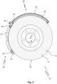
- the disc brake arrangement 10 is shown in a schematic section with the section plane running through the friction ring 14 of the brake disc 12.
- the brake disc 12 is rotatable about a rotation axis 19.
- the brake disc 12 can be designed for internal ventilation with ventilation channels (not shown in detail) in the friction ring 14.
- the disc brake arrangement 10 has a brake caliper assembly 20.
- the brake caliper assembly 20 comprises a brake caliper 22 and a brake caliper holder 24.
- the brake caliper 22 is held on the brake caliper holder 24.
- the brake caliper 22 is designed as a floating caliper.
- the brake caliper 22 is connected to the brake caliper via sliding bolts 26, see Figure 2 , guided in the axial direction on the brake caliper holder 24.
- the brake caliper holder 24 serves to fasten the brake caliper assembly 20 to a wheel carrier, not shown.
- the disc brake arrangement 10 further comprises a brake dust particle filter 28.
- the brake dust particle filter 28 comprises a filter housing 30 and a filter medium 32.
- the filter medium 32 can be a metal fiber fleece.
- the filter medium 32 is arranged in sections in the filter housing 30.
- the filter housing 30 can be U-shaped in cross section.
- the filter housing 30 extends here over a peripheral section 34 (compare Figure 2 ) of a surface 35 above the brake disc 12 and surrounds (with the legs of its U-shaped cross-section) the friction surfaces 16 of the friction ring 14 (compare Figure 1 ).
- the filter medium 32 extends over the (radially outer) circumferential section 34 on the brake disc 12. In other words, the filter medium 32 partially covers the outer surface 35 of the brake disc 12. In addition, the filter medium 32 can partially extend over the two friction surfaces 16 of the friction ring 14. For this purpose, the filter medium 32 can be arranged in a U-shape within the filter housing 30.
- the filter medium 32 projects beyond the filter housing 30 in the circumferential direction. In other words, the filter medium 32 projects out of the filter housing 30 in the circumferential direction.
- a length 36 of the projection of the filter medium 32, measured in the circumferential direction (compare Figure 2 ) can be at least 12 mm.
- the projection of the filter medium 32 is formed in the present case on the outer peripheral part of the filter medium 32; in other words, the projection of the filter medium 32 extends in the circumferential direction over the radially outer surface 35 of the brake disk 12.
- the filter medium 32 also projects in the region of the friction surfaces 16 over the filter housing 30 towards the brake caliper assembly 20 (not shown in more detail).
- the section of the filter medium 32 protruding from the filter housing 30 rests against the brake caliper assembly 20.
- the filter element 32 rests against the brake caliper holder 24.
- the filter medium 32 bridges a gap between the filter housing 30 and the brake caliper holder 24.
- the filter element 32 can be elastically and, in particular at the edge of the filter housing 30, plastically deformed.
- the filter medium 32 can extend in the circumferential direction over part of the brake caliper assembly 20. In the illustrated embodiment, the filter medium 32 overlaps the brake caliper holder 24 in the circumferential direction.
- the filter housing 30 can have several ventilation openings 38 , see Figure 1 .
- the ventilation openings 38 are located radially on the outside of the filter housing 30
- the vent openings 38 allow an air flow to exit the filter housing 30, wherein the air flow has a radial velocity component.
- the vent openings 38 are covered by the filter medium 32.
- the filter medium 32 extends on the inside of the filter housing 32 over the vent openings 38. Brake dust particles are carried along with the air flow that is conveyed into the filter housing 30 - in particular through the ventilation channels of the internally ventilated brake disc 12.
- the vent openings 38 enable the air flow to exit the filter housing 30.
- the filter medium 32 covering the vent openings 38 retains the brake dust particles. In this way, the brake dust particles are collected in the brake dust particle filter 28, more precisely its filter medium 32. Guiding the air flow through the vent openings 38 therefore increases the separation efficiency of the brake dust particle filter 28.
Landscapes
- Engineering & Computer Science (AREA)
- General Engineering & Computer Science (AREA)
- Mechanical Engineering (AREA)
- Braking Arrangements (AREA)
Description
- Die Erfindung betrifft eine Scheibenbremsanordnung aufweisend eine Bremsscheibe und eine Bremssattelbaugruppe mit einem Bremssattel. Die Erfindung betrifft ferner einen Bremsstaubpartikelfilter.
- Abrieb von Bremsen, sog. Bremsstaub, trägt zum Eintrag von Feinstaub in die Umwelt durch Kraftfahrzeuge bei. Der Abrieb besteht dabei insbesondere aus Partikeln, die von einer Bremsscheibe und Bremsbelägen abgerieben wurden. Neben der Umweltbelastung führt Bremsstaub zu hartnäckigen Verschmutzungen, welche die Funktion der Bremse und von an die Bremse angrenzenden Bauteilen beeinträchtigen können. Insbesondere auf Leichtmetallfelgen werden Ablagerungen von Bremsstaub zudem als ästhetisch störend empfunden.
- Aus
DE 10 2010 053 879 A1 ist eine Sammelvorrichtung für Bremsstaub einer Scheibenbremse bekannt. Die Scheibenbremse weist eine Bremsscheibe, einen Bremssattel und zumindest einen Bremsbelag auf. Der Bremsbelag weist eine Kapselung auf, die den Bremsbelag zumindest zum Teil umgibt. Die Kapselung weist eine Kammer auf, in welche Bremsstaub bei einem Bremsvorgang geleitet werden kann, so dass er sich dort ablagert. Ferner zeigenUS 2010/065387 A1 undDE 10 2009 021203 A1 Bremsscheibenanordnungen mit Bremsstaubfiltern. - Es ist eine Aufgabe der Erfindung, den Eintrag von Bremsstaub in eine Umgebung einer Scheibenbremse zu verringern.
- Die Aufgabe wird durch eine Scheibenbremsanordnung mit den in Anspruch 1 angegebenen Merkmalen sowie einen Bremsstaubpartikelfilter gemäß Anspruch 13 gelöst. Bevorzugte Ausführungsformen sind in den jeweiligen Unteransprüchen und der Beschreibung angegeben.
- Erfindungsgemäß ist eine Scheibenbremsanordnung vorgesehen. Die Scheibenbremsanordnung weist eine Bremsscheibe und eine Bremssattelbaugruppe mit einem Bremssattel auf. Richtungsangaben wie radial, axial oder in Umfangsrichtung beziehen sich auf eine Drehachse der Bremsscheibe. Der Bremssattel umgreift die Bremsscheibe bereichsweise. Die Bremssattelbaugruppe weist typischerweise ferner wenigstens zwei Bremsbeläge auf, die auf unterschiedlichen Seiten der Bremsscheibe angeordnet sind. Die Bremsbeläge können durch wenigstens einen Bremskolben des Bremssattels gegen einen Reibring der Bremsscheibe gepresst werden.
- Erfindungsgemäß weist die Scheibenbremsanordnung ferner einen Bremsstaubpartikelfilter mit einem Filtergehäuse und einem Filtermedium auf. Das Filtergehäuse kann die Bremsscheibe abschnittsweise umgreifen. Insbesondere kann das Filtergehäuse im Querschnitt U-förmig ausgebildet sein. Das Filtergehäuse und der Bremssattel können voneinander separate Bauteile sein. Das Filtermedium dient zum Zurückhalten und Sammeln von Bremsstaubpartikeln. Das Filtermedium ist abschnittsweise in dem Filtergehäuse angeordnet.
- Der Bremsstaubpartikelfilter kann ein unten beschriebener, erfindungsgemäßer Bremsstaubpartikelfilter sein. Merkmale des erfindungsgemäßen Bremsstaubpartikelfilters können bei dem Bremsstaubpartikelfilter der erfindungsgemäßen Scheibenbremsanordnung vorgesehen sein.
- Weiter erfindungsgemäß steht das Filtermedium in Umfangsrichtung der Bremsscheibe über das Filtergehäuse über und liegt an der Bremssattelbaugruppe an. Insbesondere kann das Filtermedium einen Spalt zwischen dem Filtergehäuse und der Bremssattelbaugruppe überbrücken. Der überstehende Abschnitt des Filtermediums kann einen mit Bremsstaubpartikeln beladenen Luftstrom aus dem Bremssattel in das Filtergehäuse leiten. In dem Filtergehäuse können die Bremsstaubpartikel besonders wirkungsvoll in dem Filtermedium abgeschieden werden. Im Bereich des Überstands des Filtermediums können keine Bremsstaubpartikel zwischen dem Filtergehäuse und der Bremssattelbaugruppe in die Umgebung entweichen. Der an der Bremssattelbaugruppe dichtend anliegende Überstand des Filtermediums über das Filtergehäuse hinaus bewirkt eine Erhöhung des Abscheidegrads des Bremsstaubpartikelfilters, da die Abdichtung der Schnittstelle verbessert ist und daher weniger abzuscheidende Partikel in die Umgebung gelangen. Die erfindungsgemäße Scheibenbremsanordnung gibt nur in einem äußerst geringen Maße mit Bremsstaubpartikel in ihre Umgebung ab.
- Das Filtermedium kann in Umfangsrichtung überlappend an der Bremssattelbaugruppe anliegen. Mit anderen Worten können das Filtermedium und die Bremssattelbaugruppe bei Blick in radialer Richtung übereinanderliegend angeordnet sein, wobei sie sich in den übereinanderliegenden Bereichen zumindest abschnittsweise berühren. Dadurch kann eine besonders wirksame Abdichtung des Filtergehäuses gegenüber der Bremssattelbaugruppe erreicht werden.
- Es kann vorgesehen sein, dass das Filtermedium unter elastischer Vorspannung an der Bremssattelbaugruppe anliegt. Die elastische Vorspannung verhindert bei Vibrationen, etwa während der Fahrt eines Kraftfahrzeugs mit der Scheibenbremsanordnung, ein Abheben des Filtermediums von der Bremssattelbaugruppe. Dadurch wird ein Eintrag von Bremsstaubpartikeln in eine Umgebung der Scheibenbremsanordnung besonders wirkungsvoll verringert.
- Alternativ oder zusätzlich kann vorgesehen sein, dass das Filtermedium durch die Anlage an der Bremssattelbaugruppe plastisch verformt ist. Durch die plastische Verformung kann das Filtermedium, insbesondere auch über größere Längenabschnitte, an einer Kontur der Bremssattelbaugruppe anliegen. Auch dies verringert einen ungewünschten Austritt von Bremsstaubpartikeln. Auch bei einer plastischen Verformung des Filtermediums ist typischerweise eine zusätzliche elastische Vorspannung des Filtermediums gegen die Bremssattelbaugruppe vorgesehen, um die gegenseitige Anlage zu gewährleisten.
- Besonders bevorzugt erstreckt sich das Filtermedium über einen Umfangsabschnitt einer Mantelfläche der Bremsscheibe. Das Filtermedium übergreift mit anderen Worten einen radial außen liegenden Mantelabschnitt der Bremsscheibe bogenförmig. Durch die Drehung der Bremsscheibe entsteht typischerweise eine nach radial außen gerichtete Luftströmung, so dass besonders viele Bremsstaubpartikel am Außenumfang der Bremsscheibe zurückgehalten werden können. Bevorzugt kann eine Umfangswand des Filtergehäuses zumindest teilweise mit dem Filtermedium ausgekleidet sein.
- Alternativ oder zusätzlich kann sich das Filtermedium in radialer Richtung, vorzugsweise beidseitig, an der Bremsscheibe erstrecken. Das Filtermedium erstreckt sich mit anderen Worten über eine oder beide Reibflächen des Reibrings der Bremsscheibe. In einer besonderen Ausführungsform können einander abgewandte Seitenwände des Filtergehäuses mit dem Filtermedium ausgekleidet sein.
- In einer bevorzugten Ausführungsform kann vorgesehen sein, dass das Filtermedium über eine der Bremssattelbaugruppe zugewandte Endkante der Umfangswand und/ oder zumindest einer der Seitenwände des Filtergehäuses übersteht. Bei einem Überstand an der Endkante der Umfangswand ergibt sich die hierin bereits beschriebene Überlappung mit der Bremssattelbaugruppe in radialer Richtung. Wenn das Filtermedium über die Endkante zumindest einer der Seitenwände übersteht erfolgt die Überlappung mit der Bremssattelbaugruppe in axialer Richtung. Es kann vorteilhaft auch vorgesehen sein, dass das Filtermedium sowohl über die Endkante der Umfangswand als auch über die Endkante zumindest einer der Seitenwände übersteht, da hierdurch die Abdichtung der Bremssattelschnittstelle weiter verbessert wird.
- In einer weiteren Ausführungsform kann das Filtergehäuse ringsegmentförmig ausgebildet sein und einen Aufnahmebereich aufweisen, mit dem es die Bremsscheibe in einem vorbestimmten Winkelbereich umgreift. Der der vorbestimmte Winkelbereich kann zumindest 20°, insbesondere zumindest 30°, beispielsweise zumindest 40° des Bremsscheibenumfangs betragen. Das Filtergehäuse umgreift bevorzugt die Bremsscheibe beidseitig, d.h. auf Seite beider Reiboberflächen. Das Filtergehäuse kann zu diesem Zweck im Längsschnitt (bezogen auf eine Rotationsachse der Bremsscheibe) eine im Wesentlichen U-förmige Gestalt aufweisen.
- Die Bremssattelbaugruppe kann einen Bremssattelhalter aufweisen, an dem der Bremssattel gehalten ist. Der Bremssattel kann an dem Bremssattelhalter in axialer Richtung verschieblich sein. Der Bremssattel kann mit anderen Worten als ein Schwimmsattel ausgebildet sein. Das Filtermedium kann an dem Bremssattelhalter anliegen. Insbesondere wenn der Bremssattelhalter einen in Drehrichtung der Bremsscheibe hinter dem Bremssattel liegenden Halteabschnitt aufweist, an dem das Filtermedium anliegt, kann dadurch die staubdichte Ankopplung des Bremsstaubpartikelfilters an die Bremssattelbaugruppe verbessert werden. An dem Halteabschnitt des Bremssattelhalters kann sich ein Bremsbelag abstützen. Der Bremssattelhalter und der Bremssattel sind grundsätzlich voneinander separate Bauteile. Der Bremssattelhalter und das Filtergehäuse können voneinander separate Bauteile sein.
- Alternativ oder zusätzlich zur Anlage an dem Bremssattelhalter kann vorgesehen sein, dass das Filtermedium an dem Bremssattel anliegt. Dadurch kann auch einen Spalt zwischen dem Bremssattel und dem Filtergehäuse bzw. einem Bremssattelhalter durch das Filtermedium überdeckt werden. Insbesondere kann das Filtermedium unmittelbar an dem Bremssattel anliegen, wenn der Bremssattel ein Festsattel ist, und die Bremssattelbaugruppe keinen separaten Bremssattelhalter aufweist.
- Die Bremsscheibe kann eine innenbelüftete Bremsscheibe sein. Dadurch kann die thermische Belastbarkeit der Scheibenbremsanordnung verbessert werden.
- Das Filtergehäuse kann wenigstens eine Entlüftungsöffnung aufweisen. Durch die Drehung der Bremsscheibe in das Filtergehäuse geförderte Luft kann durch die Entlüftungsöffnungen aus dem Filtergehäuse entweichen. Dies vermeidet, dass Luft mit Bremsstaubpartikeln an dem Bremsstaubpartikelfilter vorbeiströmt.
- Vorzugsweise eröffnet die wenigstens eine Entlüftungsöffnung das Filtergehäuse in radialer Richtung. Mit anderen Worten ermöglicht die Entlüftungsöffnung ein Ausströmen von Luft aus dem Filtergehäuse von der Mantelfläche am Außenumfang der Bremsscheibe weg. Insbesondere eine innenbelüftete Bremsscheibe bewirkt eine Förderung von Luft nach radial außen.
- Besonders bevorzugt ist die wenigstens eine Entlüftungsöffnung von dem Filtermedium überdeckt. Die in der das Filtergehäuse durchströmenden Luft mitgeführten Bremsstaubpartikel können dadurch in dem Bremsstaubpartikelfilter zurückgehalten werden.
- Ebenfalls in den Rahmen der vorliegenden Erfindung fällt ein Kraftfahrzeug mit einer erfindungsgemäßen Scheibenbremsanordnung. Die Bremsscheibe kann an einer Radnabe des Kraftfahrzeugs gehalten sein. Die Bremssattelbaugruppe, insbesondere ein Bremssattelhalter der Bremssattelbaugruppe, kann an einem Radträger des Kraftfahrzeugs gehalten sein.
- In den Rahmen der vorliegenden Erfindung fällt ferner ein Bremsstaubpartikelfilter für eine oben beschriebene, erfindungsgemäße Scheibenbremsanordnung. Merkmale des Bremsstaubpartikelfilters der erfindungsgemäßen Scheibenbremsanordnung können bei dem erfindungsgemäßen Bremsstaubpartikelfilter vorgesehen sein.
- Der erfindungsgemäße Bremsstaubpartikelfilter weist ein Filtergehäuse und ein abschnittsweise in dem Filtergehäuse angeordnetes Filtermedium auf. Erfindungsgemäß steht das Filtermedium in Umfangsrichtung über das Filtergehäuse über. Der Überstand des Filtermediums ermöglicht es, dass Filtergehäuse dicht an eine Bremssattelbaugruppe anzuschließen, wobei der Überstand des Filtermediums an der Bremssattelbaugruppe zur Anlage kommt.
- Das Filtermedium kann ein Metallfaservlies aufweisen, insbesondere als ein Metallfaservlies ausgebildet sein. Ein Metallfaservlies weist eine hohe Temperaturbeständigkeit auf. Es widersteht dadurch den an einer Scheibenbremse auftretenden Temperaturen. Ferner erlaubt es ein Metallfaservlies, Bremsstaubpartikel wirkungsvoll aus einem Luftstrom abzuschneiden. Ein Metallfaservlies kann zudem eine große Menge von Bremsstaubpartikeln aufnehmen. Alternativ oder zusätzlich kann das Filtermedium auch andere temperaturbeständige Werkstoffe aufweisen oder aus ihnen bestehen, etwa einem Glasfaservlies und/oder Keramikfaservlies
- Das Filtermedium kann in der Umfangsrichtung wenigstens 3 mm, bevorzugt wenigstens 10 mm, besonders bevorzugt wenigstens 15 mm, über das Filtergehäuse überstehen. Dies ermöglicht eine zuverlässig bremsstaubpartikeldichte Anbindung des Filtergehäuses an eine Bremssattelbaugruppe.
- Weitere Merkmale und Vorteile der Erfindung ergeben sich aus der nachfolgenden detaillierten Beschreibung eines Ausführungsbeispiels der Erfindung, aus den Patentansprüchen sowie anhand der Figuren der Zeichnung, die erfindungsgemäße Einzelheiten zeigen. Die zuvor genannten und noch weiter ausgeführten Merkmale können je einzeln für sich oder zu mehreren in beliebigen, zweckmäßigen Kombinationen bei Varianten der Erfindung verwirklicht sein. Die in der Zeichnung gezeigten Merkmale sind derart dargestellt, dass die erfindungsgemäßen Besonderheiten deutlich sichtbar gemacht werden können. In der Zeichnung zeigen:
- Fig. 1
- eine erfindungsgemäße Scheibenbremsanordnung mit einem erfindungsgemäßen Bremsstaubpartikelfilter, wobei ein Filtermedium aus einem Filtergehäuse herausragt und an einem Bremssattelhalter anliegt, in einer schematischen Perspektivansicht;
- Fig. 2
- die Scheibenbremsanordnung von
Figur 1 in einer schematischen Schnittansicht. -
Figur 1 zeigt eine Scheibenbremsanordnung 10 in einer schematischen Perspektivansicht. Die Scheibenbremsanordnung 10 weist eine Bremsscheibe 12 auf. Die Bremsscheibe 12 ist mit einem Reibring 14 mit zwei gegenüberliegenden Reibflächen 16, von denen inFigur 1 nur eine zu sehen ist, und einem Aufnahmeabschnitt 18 zur Befestigung der Bremsscheibe 12 an einer Radnabe (nicht dargestellt) ausgebildet. InFigur 2 ist die Scheibenbremsanordnung 10 in einem schematischen Schnitt mit Verlauf der Schnittebene durch den Reibring 14 der Bremsscheibe 12 dargestellt. Die Bremsscheibe 12 ist um eine Drehachse 19 drehbar. Die Bremsscheibe 12 kann zur Innenbelüftung mit nicht näher dargestellten Belüftungskanälen in dem Reibring 14 ausgebildet sein. - Die Scheibenbremsanordnung 10 weist eine Bremssattelbaugruppe 20 auf. Die Bremssattelbaugruppe 20 umfasst einen Bremssattel 22 und einen Bremssattelhalter 24. Der Bremssattel 22 ist an dem Bremssattelhalter 24 gehalten. Vorliegend ist der Bremssattel 22 als ein Schwimmsattel ausgebildet. Der Bremssattel 22 ist über Gleitbolzen 26, vergleiche
Figur 2 , in axialer Richtung verschieblich an dem Bremssattelhalter 24 geführt. Der Bremssattelhalter 24 dient zur Befestigung der Bremssattelbaugruppe 20 an einem nicht dargestellten Radträger. - Die Scheibenbremsanordnung 10 weist ferner einen Bremsstaubpartikelfilter 28 auf. Der Bremsstaubpartikelfilter 28 umfasst ein Filtergehäuse 30 und ein Filtermedium 32. Das Filtermedium 32 kann ein Metallfaservlies sein. Das Filtermedium 32 ist abschnittsweise in dem Filtergehäuse 30 angeordnet. Das Filtergehäuse 30 kann im Querschnitt U-förmig ausgebildet sein. Das Filtergehäuse 30 erstreckt sich hier über einen Umfangsabschnitt 34 (vergleiche
Figur 2 ) einer Mantelfläche 35 über der Bremsscheibe 12 und umgreift (mit den Schenkeln seines U-förmigen Querschnitts) die Reibflächen 16 des Reibrings 14 (vergleicheFigur 1 ). - Das Filtermedium 32 erstreckt sich über den (radial außen liegenden) Umfangsabschnitt 34 an der Bremsscheibe 12. Das Filtermedium 32 überdeckt mit anderen Worten bereichsweise die Mantelfläche 35 der Bremsscheibe 12. Zusätzlich kann sich das Filtermedium 32 bereichsweise über die beiden Reibflächen 16 des Reibrings 14 erstrecken. Das Filtermedium 32 kann hierzu innerhalb des Filtergehäuses 30 U-förmig angeordnet sein.
- Das Filtermedium 32 steht in Umfangsrichtung über das Filtergehäuse 30 über. Mit anderen Worten ragt das Filtermedium 32 in Umfangsrichtung aus dem Filtergehäuse 30 heraus. Eine Länge 36 des Überstands des Filtermediums 32, gemessen in der Umfangsrichtung (vergleiche
Figur 2 ) kann wenigstens 12 mm betragen. Der Überstand des Filtermediums 32 ist vorliegend am außenumfangseitigen Teil des Filtermediums 32 ausgebildet; mit anderen Worten erstreckt sich der Überstand des Filtermediums 32 in Umfangsrichtung über die radial außen liegende Mantelfläche 35 der Bremsscheibe 12. Zusätzlich könnte vorgesehen sein, dass das Filtermedium 32 auch im Bereich der Reibflächen 16 über das Filtergehäuse 30 zu der Bremssattelbaugruppe 20 hin vorsteht (nicht näher dargestellt). - Der aus dem Filtergehäuse 30 ragende Abschnitt des Filtermediums 32 liegt an der Bremssattelbaugruppe 20 an. Hier liegt das Filterelement 32 an dem Bremssattelhalter 24 an. Das Filtermedium 32 überbrückt dabei einen Spalt zwischen dem Filtergehäuse 30 und dem Bremssattelhalter 24. Zur, vorzugsweise flächigen, Anlage an der Bremssattelbaugruppe 20 kann das Filterelement 32 elastisch und, insbesondere am Rand des Filtergehäuses 30, plastisch deformiert sein. Das Filtermedium 32 kann sich in der Umfangsrichtung über einen Teil der Bremssattelbaugruppe 20 hinweg erstrecken. Im dargestellten Ausführungsbeispiel überlappt das Filtermedium 32 den Bremssattelhalter 24 in der Umfangsrichtung.
- Das Filtergehäuse 30 kann mehrere Entlüftungsöffnungen 38 aufweisen, vergleiche
Figur 1 . Die Entlüftungsöffnungen 38 sind vorliegend radial außen am Filtergehäuse 30 angeordnet. Die Entlüftungsöffnungen 38 ermöglichen ein Austreten eines Luftstroms aus dem Filtergehäuse 30, wobei der Luftstrom eine radiale Geschwindigkeitskomponente besitzt. - Die Entlüftungsöffnungen 38 sind von dem Filtermedium 32 überdeckt. Das Filtermedium 32 erstreckt sich an der Innenseite des Filtergehäuses 32 über die Entlüftungsöffnungen 38 hinweg. Mit dem Luftstrom, der - insbesondere durch die Belüftungskanäle der innenbelüfteten Bremsscheibe 12 - in das Filtergehäuse 30 gefördert wird, werden Bremsstaubpartikel mitgeführt. Die Entlüftungsöffnungen 38 ermöglichen es dem Luftstrom, aus dem Filtergehäuse 30 auszutreten. Das die Entlüftungsöffnungen 38 überdeckende Filtermedium 32 hält dabei die Bremsstaubpartikel zurück. Auf diese Weise werden die Bremsstaubpartikel in dem Bremsstaubpartikelfilter 28, genauer dessen Filtermedium 32, gesammelt. Die Führung des Luftstroms durch die Entlüftungsöffnungen 38 erhöht mithin den Abscheidegrad des Bremsstaubpartikelfilters 28.
-
- Scheibenbremsanordnung 10
- Bremsscheibe 12
- Reibring 14
- Reibflächen 16
- Aufnahmeabschnitt 18
- Drehachse 19
- Bremssattelbaugruppe 20
- Bremssattel 22
- Bremssattelhalter 24
- Gleitbolzen 26
- Bremsstaubpartikelfilter 28
- Filtergehäuse 30
- Filtermedium 32
- Umfangsabschnitt 34
- Mantelfläche 35
- Länge 36 des Überstands
- Entlüftungsöffnungen 38
Claims (15)
- Scheibenbremsanordnung (10) aufweisend- eine Bremsscheibe (12),- eine Bremssattelbaugruppe (20) mit einem Bremssattel (22), und- einen Bremsstaubpartikelfilter (28) mit einem Filtergehäuse (30) und einem abschnittsweise in dem Filtergehäuse (30) angeordneten Filtermedium (32), dadurch gekennzeichnet, dassdas Filtermedium (32) in Umfangsrichtung der Bremsscheibe (12) über das Filtergehäuse (30) übersteht und dichtend an der Bremssattelbaugruppe (20) anliegt.
- Scheibenbremsanordnung (10) nach Anspruch 1, dadurch gekennzeichnet, dass das Filtermedium (32) in Umfangsrichtung überlappend an der Bremssattelbaugruppe (20) anliegt.
- Scheibenbremsanordnung (10) nach einem der vorhergehenden Ansprüche, dadurch gekennzeichnet, dass das Filtermedium (32) unter elastischer Vorspannung an der Bremssattelbaugruppe (20) anliegt.
- Scheibenbremsanordnung (10) nach einem der vorhergehenden Ansprüche, dadurch gekennzeichnet, dass das Filtermedium (32) durch die Anlage an der Bremssattelbaugruppe (20) plastisch verformt ist.
- Scheibenbremsanordnung (10) nach einem der vorhergehenden Ansprüche, dadurch gekennzeichnet, dass das Filtermedium (32) sich über einen Umfangsabschnitt (34) einer Mantelfläche (35) der Bremsscheibe (12) erstreckt, wobei bevorzugt eine Umfangswand des Filtergehäuses (30) zumindest teilweise mit dem Filtermedium (32) ausgekleidet ist.
- Scheibenbremsanordnung (10) nach einem der vorhergehenden Ansprüche, dadurch gekennzeichnet, dass das Filtermedium (32) sich in radialer Richtung, vorzugsweise beidseitig, an der Bremsscheibe (12) erstreckt, wobei bevorzugt einander abgewandte Seitenwände des Filtergehäuses (30) zumindest teilweise mit dem Filtermedium (32) ausgekleidet sind.
- Scheibenbremsanordnung (10) nach Anspruch 5 oder 6, dadurch gekennzeichnet, dass das Filtermedium (32) über eine der Bremssattelbaugruppe (20) zugewandte Endkante der Umfangswand und/oder zumindest einer der Seitenwände des Filtergehäuses (30) übersteht.
- Scheibenbremsanordnung (10) nach einem der vorhergehenden Ansprüche, dadurch gekennzeichnet, dass das Filtergehäuse (30) ringsegmentförmig ist und einen Aufnahmebereich aufweist, mit dem es die Bremsscheibe in einem vorbestimmten Winkelbereich umgreift, wobei der vorbestimmte Winkelbereich bevorzugt zumindest 20°, stärker bevorzugt zumindest 30°, am meisten bevorzugt zumindest 40° des Bremsscheibenumfangs beträgt.
- Scheibenbremsanordnung (10) nach einem der vorhergehenden Ansprüche, dadurch gekennzeichnet, dass die Bremssattelbaugruppe (20) einen Bremssattelhalter (24) aufweist, an dem der Bremssattel (22), vorzugsweise in axialer Richtung verschieblich, gehalten ist, wobei das Filtermedium (32) insbesondere an dem Bremssattelhalter (24) anliegt.
- Scheibenbremsanordnung (10) nach einem der vorhergehenden Ansprüche, dadurch gekennzeichnet, dass das Filtermedium (32) an dem Bremssattel (22) anliegt.
- Scheibenbremsanordnung (10) nach einem der vorhergehenden Ansprüche, dadurch gekennzeichnet, dass die Bremsscheibe (12) eine innenbelüftete Bremsscheibe (12) ist.
- Scheibenbremsanordnung (10) nach einem der vorhergehenden Ansprüche, dadurch gekennzeichnet, dass das Filtergehäuse (30) wenigstens eine Entlüftungsöffnung (38) aufweist, vorzugsweise wobei die wenigstens eine Entlüftungsöffnung (38) das Filtergehäuse (30) in radialer Richtung eröffnet, wobei die wenigstens eine Entlüftungsöffnung (38) insbesondere von dem Filtermedium (32) überdeckt ist.
- Bremsstaubpartikelfilter (28) für eine Scheibenbremsanordnung (10) nach einem der vorhergehenden Ansprüche, aufweisend ein Filtergehäuse (30) und ein abschnittsweise in dem Filtergehäuse (30) angeordnetes Filtermedium (32), dadurch gekennzeichnet, dass das Filtermedium (32) in Umfangsrichtung über das Filtergehäuse (30) übersteht.
- Bremsstaubpartikelfilter (28) nach Anspruch 13, dadurch gekennzeichnet, dass das Filtermedium (32) ein Metallfaservlies, ein Glasfaservlies und/oder Keramikfaservlies aufweist oder daraus besteht.
- Bremsstaubpartikelfilter (28) nach Anspruch 13 oder 14, dadurch gekennzeichnet, dass das Filtermedium (32) in der Umfangsrichtung wenigstens 3 mm, bevorzugt wenigstens 10 mm, besonders bevorzugt wenigstens 15 mm, über das Filtergehäuse (30) übersteht.
Applications Claiming Priority (2)
| Application Number | Priority Date | Filing Date | Title |
|---|---|---|---|
| DE102021200322.2A DE102021200322A1 (de) | 2021-01-14 | 2021-01-14 | Scheibenbremsanordnung mit Bremsstaubpartikelfilter |
| PCT/EP2021/086806 WO2022152517A1 (de) | 2021-01-14 | 2021-12-20 | Scheibenbremsanordnung und bremsstaubpartikelfilter |
Publications (2)
| Publication Number | Publication Date |
|---|---|
| EP4278110A1 EP4278110A1 (de) | 2023-11-22 |
| EP4278110B1 true EP4278110B1 (de) | 2024-11-27 |
Family
ID=79601555
Family Applications (1)
| Application Number | Title | Priority Date | Filing Date |
|---|---|---|---|
| EP21843648.3A Active EP4278110B1 (de) | 2021-01-14 | 2021-12-20 | Scheibenbremsanordnung und bremsstaubpartikelfilter |
Country Status (4)
| Country | Link |
|---|---|
| US (1) | US20250012333A1 (de) |
| EP (1) | EP4278110B1 (de) |
| DE (1) | DE102021200322A1 (de) |
| WO (1) | WO2022152517A1 (de) |
Families Citing this family (3)
| Publication number | Priority date | Publication date | Assignee | Title |
|---|---|---|---|---|
| EP4403791A1 (de) * | 2023-01-18 | 2024-07-24 | MANN+HUMMEL GmbH | Filteranordnung, bremsanordnung und verfahren |
| CN116592072A (zh) * | 2023-05-18 | 2023-08-15 | 梅州市梅县区庆达实业有限公司 | 一种盘式制动器挡泥板及其制造工艺 |
| DE102023114521A1 (de) | 2023-06-02 | 2024-12-05 | Zf Cv Systems Europe Bv | Scheibenbremse für ein Kraftfahrzeug, sowie Kraftfahrzeug mit einer Scheibenbremse |
Family Cites Families (11)
| Publication number | Priority date | Publication date | Assignee | Title |
|---|---|---|---|---|
| DE102006051972A1 (de) * | 2006-11-03 | 2008-05-08 | Konstantinos Tsiberidis | Bremsstaubsammelvorrichtung |
| DE202008009717U1 (de) * | 2008-07-18 | 2009-11-26 | Mann+Hummel Gmbh | Bremsstaubaufnahmevorrichtung für Kraftfahrzeuge |
| US8926738B2 (en) | 2010-09-20 | 2015-01-06 | Idlos B.V. | Brake pad assembly and method for collecting brake particles |
| DE102010053879A1 (de) | 2010-12-09 | 2012-06-14 | Kt Projektentwicklungs Gmbh | Sammelvorrichtung für Bremsstaub |
| DE102016108793A1 (de) | 2016-05-12 | 2017-11-30 | Dr. Ing. H.C. F. Porsche Aktiengesellschaft | Scheibenbremsenanordnung mit Filterelement |
| DE102017008421A1 (de) | 2017-09-08 | 2019-03-14 | Mann+Hummel Gmbh | Bremsstaubpartikelfilter sowie Scheibenbremsenanordnung mit einem Bremsstaubpartikelfilter |
| DE102017008423A1 (de) * | 2017-09-08 | 2019-03-14 | Mann+Hummel Gmbh | Bremsstaubpartikelfilter sowie Scheibenbremsenanordnung mit einem Bremsstaubpartikelfilter |
| EP3797229B1 (de) | 2018-05-22 | 2022-10-19 | MANN+HUMMEL GmbH | Bremsstaubpartikelfilter sowie scheibenbremsenanordnung mit einem bremsstaubpartikelfilter |
| WO2021083629A1 (en) | 2019-10-28 | 2021-05-06 | Mann+Hummel Gmbh | Brake dust particle filter, disc brake assembly and method for collecting brake dust particles |
| KR102538298B1 (ko) * | 2020-12-29 | 2023-05-30 | 한국세라믹기술원 | 수송기관의 브레이크 장치에서 발생한 미세먼지를 포집하기 위한 포집장치 및 그 제조방법 |
| DE102021114797B4 (de) * | 2021-06-09 | 2024-11-07 | Mann+Hummel Gmbh | Bremsstaubpartikelfilter mit einem Filtereinsatz |
-
2021
- 2021-01-14 DE DE102021200322.2A patent/DE102021200322A1/de active Pending
- 2021-12-20 WO PCT/EP2021/086806 patent/WO2022152517A1/de not_active Ceased
- 2021-12-20 US US18/272,313 patent/US20250012333A1/en active Pending
- 2021-12-20 EP EP21843648.3A patent/EP4278110B1/de active Active
Also Published As
| Publication number | Publication date |
|---|---|
| US20250012333A1 (en) | 2025-01-09 |
| WO2022152517A1 (de) | 2022-07-21 |
| DE102021200322A1 (de) | 2022-07-14 |
| EP4278110A1 (de) | 2023-11-22 |
Similar Documents
| Publication | Publication Date | Title |
|---|---|---|
| EP3797229B1 (de) | Bremsstaubpartikelfilter sowie scheibenbremsenanordnung mit einem bremsstaubpartikelfilter | |
| EP3874176B1 (de) | Bremsstaubpartikelfilter, bremssattel und scheibenbremsanordnung | |
| EP2585730B1 (de) | Scheibenbremse | |
| WO2022069138A1 (de) | Scheibenbremsanordnung, bremssattelbaugruppe und bremssattelhalter | |
| EP4419810B1 (de) | Scheibenbremse | |
| EP4278110A1 (de) | Scheibenbremsanordnung und bremsstaubpartikelfilter | |
| DE102020125273A1 (de) | Bremsstaubpartikelfilter, Scheibenbremsenanordnung und Filtereinsatzteil | |
| WO2019048377A9 (de) | Bremsstaubpartikelfilter sowie scheibenbremsenanordnung mit einem bremsstaubpartikelfilter | |
| EP3963229B1 (de) | Bremsscheibenanordnung mit einem bremsstaubpartikelfilter | |
| DE102021114796B4 (de) | Bremsstaubpartikelfilter, Scheibenbremsenanordnung, Verwendung eines Filters und Verfahren zum Filtern von bremsstaubbeladener Luft | |
| DE102019210997A1 (de) | Trommelbremse und Fahrzeug mit einer Trommelbremse | |
| DE102021126787A1 (de) | Scheibenbremse und Absauganordnung | |
| DE102020216507A1 (de) | Magnetband zum Auffangen von Bremsabriebspartikeln bei Radfelgen | |
| DE102020105241A1 (de) | Vorrichtung zum Sammeln von Bremsstaub mit einer eine Strömung von einer Bremsscheibe trennenden Schneide | |
| DE102020126890A1 (de) | Scheibenbremsvorrichtung, Fahrzeug und Bremsbelag | |
| DE102020118880A1 (de) | Bremssattelträger, Scheibenbremsenanordnung, Verwendung eines Bremssattelträgers und Verfahren zum Leiten von Luft | |
| EP3516256B1 (de) | Verbundbremsscheibe | |
| WO2021213738A1 (de) | Bremsstaubpartikelfilter, scheibenbremsenanordnung, verwendung eines bremsstaubpartikelfilters und verfahren zum filtern von bremsstaubbeladener luft | |
| WO2022078810A1 (de) | Bremsbelag für eine scheibenbremsanordnung | |
| WO2021245041A1 (de) | Bremssattelvorrichtung, scheibenbremsenanordnung, verwendung einer bremssattelvorrichtung und verfahren zum radialen rückhalten von luft | |
| WO2021083622A1 (de) | Bremsstaubpartikelfilter, scheibenbremsenanordnung, verwendung eines filters und verfahren zum filtern von bremsstaubbeladener luft | |
| EP4495449B1 (de) | Fahrzeugbremsstaub-sammeleinrichtung und fahrzeugbremseinrichtung | |
| DE102020111811A1 (de) | Bremsstaubpartikelfilter, Scheibenbremsenanordnung und Verwendung eines Bremsstaubpartikelfilters | |
| EP1191245A2 (de) | Abdeckblech für Scheibenbremsen | |
| WO2022194854A1 (de) | Scheibenbremseinrichtung für ein kraftfahrzeug |
Legal Events
| Date | Code | Title | Description |
|---|---|---|---|
| STAA | Information on the status of an ep patent application or granted ep patent |
Free format text: STATUS: UNKNOWN |
|
| STAA | Information on the status of an ep patent application or granted ep patent |
Free format text: STATUS: THE INTERNATIONAL PUBLICATION HAS BEEN MADE |
|
| PUAI | Public reference made under article 153(3) epc to a published international application that has entered the european phase |
Free format text: ORIGINAL CODE: 0009012 |
|
| STAA | Information on the status of an ep patent application or granted ep patent |
Free format text: STATUS: REQUEST FOR EXAMINATION WAS MADE |
|
| 17P | Request for examination filed |
Effective date: 20230620 |
|
| AK | Designated contracting states |
Kind code of ref document: A1 Designated state(s): AL AT BE BG CH CY CZ DE DK EE ES FI FR GB GR HR HU IE IS IT LI LT LU LV MC MK MT NL NO PL PT RO RS SE SI SK SM TR |
|
| DAV | Request for validation of the european patent (deleted) | ||
| DAX | Request for extension of the european patent (deleted) | ||
| GRAP | Despatch of communication of intention to grant a patent |
Free format text: ORIGINAL CODE: EPIDOSNIGR1 |
|
| STAA | Information on the status of an ep patent application or granted ep patent |
Free format text: STATUS: GRANT OF PATENT IS INTENDED |
|
| INTG | Intention to grant announced |
Effective date: 20240802 |
|
| GRAS | Grant fee paid |
Free format text: ORIGINAL CODE: EPIDOSNIGR3 |
|
| GRAA | (expected) grant |
Free format text: ORIGINAL CODE: 0009210 |
|
| STAA | Information on the status of an ep patent application or granted ep patent |
Free format text: STATUS: THE PATENT HAS BEEN GRANTED |
|
| AK | Designated contracting states |
Kind code of ref document: B1 Designated state(s): AL AT BE BG CH CY CZ DE DK EE ES FI FR GB GR HR HU IE IS IT LI LT LU LV MC MK MT NL NO PL PT RO RS SE SI SK SM TR |
|
| P01 | Opt-out of the competence of the unified patent court (upc) registered |
Free format text: CASE NUMBER: APP_57507/2024 Effective date: 20241022 |
|
| REG | Reference to a national code |
Ref country code: GB Ref legal event code: FG4D Free format text: NOT ENGLISH |
|
| REG | Reference to a national code |
Ref country code: CH Ref legal event code: EP |
|
| REG | Reference to a national code |
Ref country code: IE Ref legal event code: FG4D Free format text: LANGUAGE OF EP DOCUMENT: GERMAN |
|
| REG | Reference to a national code |
Ref country code: DE Ref legal event code: R096 Ref document number: 502021005963 Country of ref document: DE |
|
| REG | Reference to a national code |
Ref country code: LT Ref legal event code: MG9D |
|
| REG | Reference to a national code |
Ref country code: NL Ref legal event code: MP Effective date: 20241127 |
|
| PG25 | Lapsed in a contracting state [announced via postgrant information from national office to epo] |
Ref country code: HR Free format text: LAPSE BECAUSE OF FAILURE TO SUBMIT A TRANSLATION OF THE DESCRIPTION OR TO PAY THE FEE WITHIN THE PRESCRIBED TIME-LIMIT Effective date: 20241127 Ref country code: IS Free format text: LAPSE BECAUSE OF FAILURE TO SUBMIT A TRANSLATION OF THE DESCRIPTION OR TO PAY THE FEE WITHIN THE PRESCRIBED TIME-LIMIT Effective date: 20250327 Ref country code: PT Free format text: LAPSE BECAUSE OF FAILURE TO SUBMIT A TRANSLATION OF THE DESCRIPTION OR TO PAY THE FEE WITHIN THE PRESCRIBED TIME-LIMIT Effective date: 20250327 |
|
| PG25 | Lapsed in a contracting state [announced via postgrant information from national office to epo] |
Ref country code: FI Free format text: LAPSE BECAUSE OF FAILURE TO SUBMIT A TRANSLATION OF THE DESCRIPTION OR TO PAY THE FEE WITHIN THE PRESCRIBED TIME-LIMIT Effective date: 20241127 Ref country code: NL Free format text: LAPSE BECAUSE OF FAILURE TO SUBMIT A TRANSLATION OF THE DESCRIPTION OR TO PAY THE FEE WITHIN THE PRESCRIBED TIME-LIMIT Effective date: 20241127 |
|
| PG25 | Lapsed in a contracting state [announced via postgrant information from national office to epo] |
Ref country code: BG Free format text: LAPSE BECAUSE OF FAILURE TO SUBMIT A TRANSLATION OF THE DESCRIPTION OR TO PAY THE FEE WITHIN THE PRESCRIBED TIME-LIMIT Effective date: 20241127 |
|
| PG25 | Lapsed in a contracting state [announced via postgrant information from national office to epo] |
Ref country code: ES Free format text: LAPSE BECAUSE OF FAILURE TO SUBMIT A TRANSLATION OF THE DESCRIPTION OR TO PAY THE FEE WITHIN THE PRESCRIBED TIME-LIMIT Effective date: 20241127 |
|
| PG25 | Lapsed in a contracting state [announced via postgrant information from national office to epo] |
Ref country code: NO Free format text: LAPSE BECAUSE OF FAILURE TO SUBMIT A TRANSLATION OF THE DESCRIPTION OR TO PAY THE FEE WITHIN THE PRESCRIBED TIME-LIMIT Effective date: 20250227 |
|
| PG25 | Lapsed in a contracting state [announced via postgrant information from national office to epo] |
Ref country code: GR Free format text: LAPSE BECAUSE OF FAILURE TO SUBMIT A TRANSLATION OF THE DESCRIPTION OR TO PAY THE FEE WITHIN THE PRESCRIBED TIME-LIMIT Effective date: 20250228 Ref country code: LV Free format text: LAPSE BECAUSE OF FAILURE TO SUBMIT A TRANSLATION OF THE DESCRIPTION OR TO PAY THE FEE WITHIN THE PRESCRIBED TIME-LIMIT Effective date: 20241127 |
|
| PG25 | Lapsed in a contracting state [announced via postgrant information from national office to epo] |
Ref country code: PL Free format text: LAPSE BECAUSE OF FAILURE TO SUBMIT A TRANSLATION OF THE DESCRIPTION OR TO PAY THE FEE WITHIN THE PRESCRIBED TIME-LIMIT Effective date: 20241127 |
|
| PG25 | Lapsed in a contracting state [announced via postgrant information from national office to epo] |
Ref country code: RS Free format text: LAPSE BECAUSE OF FAILURE TO SUBMIT A TRANSLATION OF THE DESCRIPTION OR TO PAY THE FEE WITHIN THE PRESCRIBED TIME-LIMIT Effective date: 20250227 |
|
| PG25 | Lapsed in a contracting state [announced via postgrant information from national office to epo] |
Ref country code: SM Free format text: LAPSE BECAUSE OF FAILURE TO SUBMIT A TRANSLATION OF THE DESCRIPTION OR TO PAY THE FEE WITHIN THE PRESCRIBED TIME-LIMIT Effective date: 20241127 |
|
| PG25 | Lapsed in a contracting state [announced via postgrant information from national office to epo] |
Ref country code: DK Free format text: LAPSE BECAUSE OF FAILURE TO SUBMIT A TRANSLATION OF THE DESCRIPTION OR TO PAY THE FEE WITHIN THE PRESCRIBED TIME-LIMIT Effective date: 20241127 |
|
| PG25 | Lapsed in a contracting state [announced via postgrant information from national office to epo] |
Ref country code: EE Free format text: LAPSE BECAUSE OF FAILURE TO SUBMIT A TRANSLATION OF THE DESCRIPTION OR TO PAY THE FEE WITHIN THE PRESCRIBED TIME-LIMIT Effective date: 20241127 |
|
| PG25 | Lapsed in a contracting state [announced via postgrant information from national office to epo] |
Ref country code: RO Free format text: LAPSE BECAUSE OF FAILURE TO SUBMIT A TRANSLATION OF THE DESCRIPTION OR TO PAY THE FEE WITHIN THE PRESCRIBED TIME-LIMIT Effective date: 20241127 |
|
| PG25 | Lapsed in a contracting state [announced via postgrant information from national office to epo] |
Ref country code: SK Free format text: LAPSE BECAUSE OF FAILURE TO SUBMIT A TRANSLATION OF THE DESCRIPTION OR TO PAY THE FEE WITHIN THE PRESCRIBED TIME-LIMIT Effective date: 20241127 |
|
| PG25 | Lapsed in a contracting state [announced via postgrant information from national office to epo] |
Ref country code: CZ Free format text: LAPSE BECAUSE OF FAILURE TO SUBMIT A TRANSLATION OF THE DESCRIPTION OR TO PAY THE FEE WITHIN THE PRESCRIBED TIME-LIMIT Effective date: 20241127 |
|
| PG25 | Lapsed in a contracting state [announced via postgrant information from national office to epo] |
Ref country code: IT Free format text: LAPSE BECAUSE OF FAILURE TO SUBMIT A TRANSLATION OF THE DESCRIPTION OR TO PAY THE FEE WITHIN THE PRESCRIBED TIME-LIMIT Effective date: 20241127 |
|
| REG | Reference to a national code |
Ref country code: CH Ref legal event code: PL |
|
| PG25 | Lapsed in a contracting state [announced via postgrant information from national office to epo] |
Ref country code: LU Free format text: LAPSE BECAUSE OF NON-PAYMENT OF DUE FEES Effective date: 20241220 |
|
| REG | Reference to a national code |
Ref country code: DE Ref legal event code: R097 Ref document number: 502021005963 Country of ref document: DE |
|
| PG25 | Lapsed in a contracting state [announced via postgrant information from national office to epo] |
Ref country code: SE Free format text: LAPSE BECAUSE OF FAILURE TO SUBMIT A TRANSLATION OF THE DESCRIPTION OR TO PAY THE FEE WITHIN THE PRESCRIBED TIME-LIMIT Effective date: 20241127 |
|
| PG25 | Lapsed in a contracting state [announced via postgrant information from national office to epo] |
Ref country code: MC Free format text: LAPSE BECAUSE OF FAILURE TO SUBMIT A TRANSLATION OF THE DESCRIPTION OR TO PAY THE FEE WITHIN THE PRESCRIBED TIME-LIMIT Effective date: 20241127 |
|
| PLBE | No opposition filed within time limit |
Free format text: ORIGINAL CODE: 0009261 |
|
| STAA | Information on the status of an ep patent application or granted ep patent |
Free format text: STATUS: NO OPPOSITION FILED WITHIN TIME LIMIT |
|
| REG | Reference to a national code |
Ref country code: BE Ref legal event code: MM Effective date: 20241231 |
|
| PG25 | Lapsed in a contracting state [announced via postgrant information from national office to epo] |
Ref country code: BE Free format text: LAPSE BECAUSE OF NON-PAYMENT OF DUE FEES Effective date: 20241231 |
|
| PG25 | Lapsed in a contracting state [announced via postgrant information from national office to epo] |
Ref country code: FR Free format text: LAPSE BECAUSE OF NON-PAYMENT OF DUE FEES Effective date: 20250127 |
|
| PG25 | Lapsed in a contracting state [announced via postgrant information from national office to epo] |
Ref country code: CH Free format text: LAPSE BECAUSE OF NON-PAYMENT OF DUE FEES Effective date: 20241231 |
|
| PG25 | Lapsed in a contracting state [announced via postgrant information from national office to epo] |
Ref country code: IE Free format text: LAPSE BECAUSE OF NON-PAYMENT OF DUE FEES Effective date: 20241220 |
|
| 26N | No opposition filed |
Effective date: 20250828 |
|
| PGFP | Annual fee paid to national office [announced via postgrant information from national office to epo] |
Ref country code: AT Payment date: 20260113 Year of fee payment: 5 |
|
| PGFP | Annual fee paid to national office [announced via postgrant information from national office to epo] |
Ref country code: DE Payment date: 20251229 Year of fee payment: 5 |
|
| PG25 | Lapsed in a contracting state [announced via postgrant information from national office to epo] |
Ref country code: CY Free format text: LAPSE BECAUSE OF FAILURE TO SUBMIT A TRANSLATION OF THE DESCRIPTION OR TO PAY THE FEE WITHIN THE PRESCRIBED TIME-LIMIT Effective date: 20241127 |