EP4276439B1 - Automatische trennvorrichtung und verwendungsverfahren dafür - Google Patents
Automatische trennvorrichtung und verwendungsverfahren dafür Download PDFInfo
- Publication number
- EP4276439B1 EP4276439B1 EP22755592.7A EP22755592A EP4276439B1 EP 4276439 B1 EP4276439 B1 EP 4276439B1 EP 22755592 A EP22755592 A EP 22755592A EP 4276439 B1 EP4276439 B1 EP 4276439B1
- Authority
- EP
- European Patent Office
- Prior art keywords
- bottom plate
- inclined bottom
- separation device
- chute
- probe
- Prior art date
- Legal status (The legal status is an assumption and is not a legal conclusion. Google has not performed a legal analysis and makes no representation as to the accuracy of the status listed.)
- Active
Links
Images





Classifications
-
- G—PHYSICS
- G01—MEASURING; TESTING
- G01N—INVESTIGATING OR ANALYSING MATERIALS BY DETERMINING THEIR CHEMICAL OR PHYSICAL PROPERTIES
- G01N1/00—Sampling; Preparing specimens for investigation
- G01N1/02—Devices for withdrawing samples
- G01N1/10—Devices for withdrawing samples in the liquid or fluent state
-
- G—PHYSICS
- G01—MEASURING; TESTING
- G01K—MEASURING TEMPERATURE; MEASURING QUANTITY OF HEAT; THERMALLY-SENSITIVE ELEMENTS NOT OTHERWISE PROVIDED FOR
- G01K13/00—Thermometers specially adapted for specific purposes
- G01K13/12—Thermometers specially adapted for specific purposes combined with sampling devices for measuring temperatures of samples of materials
-
- B—PERFORMING OPERATIONS; TRANSPORTING
- B26—HAND CUTTING TOOLS; CUTTING; SEVERING
- B26D—CUTTING; DETAILS COMMON TO MACHINES FOR PERFORATING, PUNCHING, CUTTING-OUT, STAMPING-OUT OR SEVERING
- B26D7/00—Details of apparatus for cutting, cutting-out, stamping-out, punching, perforating, or severing by means other than cutting
-
- B—PERFORMING OPERATIONS; TRANSPORTING
- B26—HAND CUTTING TOOLS; CUTTING; SEVERING
- B26D—CUTTING; DETAILS COMMON TO MACHINES FOR PERFORATING, PUNCHING, CUTTING-OUT, STAMPING-OUT OR SEVERING
- B26D7/00—Details of apparatus for cutting, cutting-out, stamping-out, punching, perforating, or severing by means other than cutting
- B26D7/0006—Means for guiding the cutter
-
- G—PHYSICS
- G01—MEASURING; TESTING
- G01K—MEASURING TEMPERATURE; MEASURING QUANTITY OF HEAT; THERMALLY-SENSITIVE ELEMENTS NOT OTHERWISE PROVIDED FOR
- G01K13/00—Thermometers specially adapted for specific purposes
- G01K13/12—Thermometers specially adapted for specific purposes combined with sampling devices for measuring temperatures of samples of materials
- G01K13/125—Thermometers specially adapted for specific purposes combined with sampling devices for measuring temperatures of samples of materials for siderurgical purposes
-
- G—PHYSICS
- G01—MEASURING; TESTING
- G01N—INVESTIGATING OR ANALYSING MATERIALS BY DETERMINING THEIR CHEMICAL OR PHYSICAL PROPERTIES
- G01N1/00—Sampling; Preparing specimens for investigation
- G01N1/02—Devices for withdrawing samples
- G01N1/10—Devices for withdrawing samples in the liquid or fluent state
- G01N1/12—Dippers; Dredgers
- G01N1/125—Dippers; Dredgers adapted for sampling molten metals
-
- G—PHYSICS
- G01—MEASURING; TESTING
- G01N—INVESTIGATING OR ANALYSING MATERIALS BY DETERMINING THEIR CHEMICAL OR PHYSICAL PROPERTIES
- G01N1/00—Sampling; Preparing specimens for investigation
- G01N1/28—Preparing specimens for investigation including physical details of (bio-)chemical methods covered elsewhere, e.g. G01N33/50, C12Q
- G01N1/286—Preparing specimens for investigation including physical details of (bio-)chemical methods covered elsewhere, e.g. G01N33/50, C12Q involving mechanical work, e.g. chopping, disintegrating, compacting, homogenising
-
- G—PHYSICS
- G01—MEASURING; TESTING
- G01N—INVESTIGATING OR ANALYSING MATERIALS BY DETERMINING THEIR CHEMICAL OR PHYSICAL PROPERTIES
- G01N1/00—Sampling; Preparing specimens for investigation
- G01N1/02—Devices for withdrawing samples
- G01N1/10—Devices for withdrawing samples in the liquid or fluent state
- G01N2001/1031—Sampling from special places
-
- G—PHYSICS
- G01—MEASURING; TESTING
- G01N—INVESTIGATING OR ANALYSING MATERIALS BY DETERMINING THEIR CHEMICAL OR PHYSICAL PROPERTIES
- G01N1/00—Sampling; Preparing specimens for investigation
- G01N1/28—Preparing specimens for investigation including physical details of (bio-)chemical methods covered elsewhere, e.g. G01N33/50, C12Q
- G01N1/286—Preparing specimens for investigation including physical details of (bio-)chemical methods covered elsewhere, e.g. G01N33/50, C12Q involving mechanical work, e.g. chopping, disintegrating, compacting, homogenising
- G01N2001/2873—Cutting or cleaving
-
- Y—GENERAL TAGGING OF NEW TECHNOLOGICAL DEVELOPMENTS; GENERAL TAGGING OF CROSS-SECTIONAL TECHNOLOGIES SPANNING OVER SEVERAL SECTIONS OF THE IPC; TECHNICAL SUBJECTS COVERED BY FORMER USPC CROSS-REFERENCE ART COLLECTIONS [XRACs] AND DIGESTS
- Y02—TECHNOLOGIES OR APPLICATIONS FOR MITIGATION OR ADAPTATION AGAINST CLIMATE CHANGE
- Y02P—CLIMATE CHANGE MITIGATION TECHNOLOGIES IN THE PRODUCTION OR PROCESSING OF GOODS
- Y02P10/00—Technologies related to metal processing
- Y02P10/20—Recycling
Definitions
- the present invention relates to the technical field of metallurgy, in particular to a sampling probe, an automatic separation device, and a use method thereof.
- the outer side of the currently used sampling probe consists of a tubular paper housing, and the inner side of the probe has various forms according to different metal sample mold boxes.
- One of the more common forms is a cylindrical flat sample, and a housing of a mold box for the sample is of a two-piece structure which is fixed into a whole by a metal clamp. This metal clamp is used to ensure that the two-piece mold box housing is always kept in the combined state in the process that the sampled molten metal is solidified therein, so that the obtained solidified sample of the molten metal is a regular cylinder with no burr at the edge.
- Chinese patent CN203545142U discloses a device for automatically exposing a sample, wherein a probe is first fixed by a supporting device on its outer surface, the probe with the sample is partitioned by a partitioning device, and the sample with a housing is squeezed out from the partitioned area of the probe by means of a punch.
- a filling material including the housing and the sample is introduced into a housing dismantling device through an introduction device, wherein the housing includes a clamp for keeping the sample housing closed while sampling.
- the housing dismantling device includes a bottom plate, a vibration motor, a centrifugal device, a colliding body, and the like. The bottom plate inclines downwards, and the bottom of the bottom plate is provided with the vibration motor.
- the sample By means of the vibration of the bottom plate, the sample is moved towards the centrifugal device in the housing dismantling device.
- the gap below the centrifugal device is sized only to pass the separated sample and housing, and the unseparated sample and housing obtains an impulse towards the colliding body by the centrifugal device.
- the object By the collision of the colliding body, the object will be disassembled in most cases.
- the disassembled sample, housing and filling material pass through the gap below the centrifugal device to move towards a sample extraction area.
- the disassembled sample, housing and filling material are blocked by a blocking layer on which a channel for the housing and the filling material is arranged, so that the housing and the filling material are separated through the channel, and the sample cannot pass through the channel due to its size, therefore the sample is guided by the blocking layer and finally enters the sample extraction area.
- the device has a large number of actuation mechanisms, complex structure, high cost, heavy post-maintenance work and the reliability is difficult to guarantee.
- the method of enabling the housing component with the clamp to hit the colliding body by means of the centrifugal device can only ensure that the sample is separated from the housing in most cases, but it is difficult to deal with a situation when the clamp is assembled too tight and difficult to separate the sample from the housing.
- the device has no constraint on the posture of each component, so that jamming at the gap between the centrifugal device and the bottom plate will easily occur due to arbitrary postures of the components.
- Patent WO2020/038662A1 , CN111426528A , and CN203545142U disclose sampling probes, separation devices and methods for automatically separating metal samples from the sampling probes.
- an objective of the present invention is to provide a sampling probe, an automatic separation device, and a use method thereof, which can not only effectively solve the problem of hard separation between the sample and the housing, but also avoid the jamming between the actuation mechanism and the components by the constraint on the posture of each component.
- an automatic separation device for a sampling probe comprising a probe tail area and a probe sampling area connected to a top of the probe tail area, wherein the probe sampling area comprises a housing, a two-piece mold housing component being disposed in the housing, and a sample being disposed inside the two-piece mold housing component, and wherein the two-piece mold housing component is wound and fixed by an adhesive tape capable of burning and melting,the automatic separation device comprising a cutting device for cutting the probe sampling area in the sampling probe, and an inclined bottom plate, wherein the inclined bottom plate is inclined downward from the front end to the rear end, with the front end of the inclined bottom plate being close to the cutting device and the rear end of the inclined bottom plate being placed away from the cutting device;characterised in that a first posture adjustment device, a first separation device, a second posture adjustment device, and a second separation device are sequentially arranged between the front end of the inclined bottom plate and the rear end of the inclined bottom plate, and in that the first posture adjustment device, the first separation device, the second posture adjustment
- the cutting device is used for cutting the probe sampling area containing the sample and the two-piece mold housing component from the sampling probe, and a cutting plane of the cutting device is located at an opening of a guide channel for the flat cylindrical sample and the two-piece mold housing component, and is tangent to the side face of a cylinder formed when the two-piece mold housing component is in a combined state.
- the first posture adjustment device includes at least two collision points that are sequentially disposed in the direction from the front end of the inclined bottom plate to the rear end of the inclined bottom plate, or at least two collision points are sequentially disposed on the upper surface of the inclined bottom plate from the upper end to the lower end; and/or an optional range of the cutting device includes, but is not limited to, a shearing device, a squeezing device or a sawing device.
- the collision points include a turnover collision point and a constraining collision point; wherein the turnover collision point is used for abutting against the end face of the probe sampling area falling onto the inclined bottom plate after cutting, and the constraining collision point is used for abutting against the peripheral side of the probe sampling area; that is to say, after being sheared by the cutting device, the probe sampling area is separated from the sampling probe and enters an area where the inclined bottom plate is located.
- the turnover collision point can abut against the end face of the probe sampling area, and the constraining collision point can abut against the peripheral side of the probe sampling area.
- the distance between the turnover collision point and the constraining collision point on the upper surface of the inclined bottom plate is not smaller than the radius of the end face of the probe sampling area.
- This solution is adopted so that it is possible to constrain the probe sampling area from rushing out of the inclined bottom plate after collision. If the distance between the turnover collision point and the constraining collision point on the upper surface of the inclined bottom plate is smaller than the radius of the end face of the probe sampling area, the probe sampling area will be subjected to a component force opposite to the direction of gravity during collision, causing the probe sampling area to rush out in a suspended manner.
- the first separation device includes a first side plate, a second side plate and a turnover plate;
- the height of the first side plate and the height of the second side plate are both greater than the cross-sectional radius of the housing of the probe sampling area to prevent the housing of the probe sampling area from being overturned out of the first chute.
- the second posture adjustment device includes a second chute, and the inlet of the second chute communicates with the outlet of the first chute.
- the inner side wall of the second chute is set as a curved surface with angle changes so as to guide the two-piece mold housing component and the sample therein to gradually change from a lying position when entering the second chute to a state of rolling upright along the side face.
- the specific shape of the second chute is not particularly limited as long as the above objective can be achieved.
- the second separation device includes the third side plate, the fourth side plate and a sample extraction area;
- the third chute is arranged as a structure that gradually becomes larger in the direction from the front end to the rear end of the inclined bottom plate, and the inclination angles of the third side plate and the fourth side plate gradually increase in the direction from the front end to the rear end of the inclined bottom plate.
- the third side plate and the fourth side plate are gradually overturned outwards from the front end to the rear end, or the inclination angles of the third side plate and the fourth side plate with respect to the opposite directions gradually increase.
- the size of the inlet of the third chute is greater than the height of the cylinder formed when the two-piece mold housing component is in the combined state, and smaller than the diameter of the cylinder formed when the two-piece mold housing component is in the combined state.
- the distance between the third side plate and the fourth side plate at the inlet of the third chute is greater than the height of the cylinder formed when the two-piece mold housing component is in the combined state, and smaller than the diameter of the cylinder formed when the two-piece mold housing component is in the combined state so as to guide the two-piece mold housing component to roll along the side face of the cylinder.
- the turnover plate is connected to the lower surface of the inclined bottom plate by an adjustable hinge.
- the lower end (or tail) of the third chute is further provided with a partitioning plate.
- the lower end of the third chute (or the position close to the tail) is provided with a rectangular opening, and the rectangular opening is provided with a blocking plate on its edge close to the sample extraction area, that is, the end of the rectangular opening is provided with a blocking plate.
- the inclined bottom plate includes a first inclined bottom plate and a second inclined bottom plate connected to the rear end of the first inclined bottom plate.
- the inclination angle of the inclined bottom plate is 30°.
- the included angle between the inclined bottom plate and the horizontal direction is 30°, so as to guide the sample to move on the automatic separation device from the front end to the rear end.
- the inclined bottom plates can have different inclination angles.
- a use method of the automatic separation device which includes the following steps:
- the adjusting in step 5) specifically includes the following steps:
- the inclination angle of the inclined bottom plate is adjusted to 30°.
- sampling probe the sample automatic separation device and the use method thereof provided by the present invention further have the following beneficial effects:
- a sampling probe provided by the present invention includes a probe tail area 1 and a probe sampling area 2 connected to the top of the probe tail area 1;
- the probe sampling area 2 includes a paper housing, a two-piece mold housing component 3 disposed in the paper housing, and a sample 4 disposed in the two-piece mold housing component 3;
- the two-piece mold housing component 3 is wound and fixed by an adhesive tape capable of burning and melting.
- the cutting device 5 places the sampling probe, whose sampling is completed, in a direction perpendicular to the acting direction of the cutting device 5 in Fig. 1 , so as to cut the sampling probe into two parts, i.e., the probe tail area 1 and the probe sampling area 2.
- the cutting plane formed by the acting direction of the cutting device 5 is located at the guide channel 6 of the flat cylinder and the two-piece mold housing component 3 and is tangent to the cylindrical side face formed when the two-piece mold housing component 3 is in the combined state.
- the function of the cutting device 5 is to extrude and deform the paper housing of the sampling probe, and the deformed opening shape is favorable for the two-piece mold housing component 3 and the sample 4 to fall out.
- the two-piece mold housing component 3 is wound and fixed by an adhesive tape capable of burning and melting during assembly, and during sampling, the two-piece mold housing component 3 is kept in the combined state under the action of the adhesive tape capable of burning and melting; after the sample 4 is taken, the adhesive tape capable of burning and melting is burned and melted by molten metal, and then, the molten metal entering the two-piece mold housing component 3 through the guide channel 6 is solidified into a solid state.
- the cutting device 5 By the action of the cutting device 5, the sample 4 in the two-piece mold housing component 3 and shank-shaped metal formed by the high-temperature metal flowing through the guide channel 6 will be broken and separated, and the sample 4 is a regular flat cylinder.
- a sampling probe automatic separation device provided by the present invention includes a cutting device 5 for cutting a sampling probe, and an inclined bottom plate located downstream of the cutting device 5.
- the inclined bottom plate inclines downwards from the front end to the rear end, the upper end (i.e., the front end) of the inclined bottom plate is placed close to the cutting device 5; the lower end (i.e., the rear end) of the inclined bottom plate is far away from the cutting device 5 and is lower than the horizontal plane where the front end is located.
- the downward inclination angle of the inclined bottom plate is 30°, i.e., the included angle between the inclined bottom plate and the horizontal plane is 30°.
- the inclined bottom plate can include a first inclined bottom plate 7, and a second inclined bottom plate 8 connected to the lower end (or the rear end) of the first inclined bottom plate 7.
- the first inclined bottom plate 7 and the second inclined bottom plate 8 are the same plate.
- a first posture adjustment device 9, a first separation device 10, a second posture adjustment device 11 and a second separation device 12 are sequentially arranged between the upper end of the inclined bottom plate and the lower end of the inclined bottom plate.
- the probe sampling area 2 falls onto the first inclined bottom plate 7, and the probe sampling area 2 changes from horizontal state to a state of sliding down along the first inclined bottom plate 7.
- the first posture adjustment device 9 includes a constraining collision point 901 (the constraining collision point 901 in this embodiment is a slender rod), a turnover collision point 902 (the turnover collision point 902 in this embodiment is also a slender rod) and a plurality of guide points 903 (the guide point 903 in this embodiment is a guide rod, i.e., slender rod, which can play a role in guiding according to the set position), which are arranged in sequence from the upper end of the inclined bottom plate to the lower end of the inclined bottom plate and are all mounted on the upper surface of the first inclined bottom plate 7.
- the turnover collision point 902 provides one turnover collision point
- the constraining collision point 901 provides one constraining collision point
- the present application does not limit the number of turnover collision points and constraining collision points.
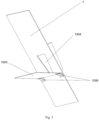
- the slid down end face of the probe sampling area 2 collides with the turnover collision point 902 (as shown in Fig. 4 ), and the side face of the probe sampling area 2 collides with the constraining collision point 901 and then is laterally overturned so that the open side of the two-piece mold housing component 3 with the sample 4 gradually faces downwards and is guided by the guide points 903 to fall into the first separation device 10.
- the first separation device 10 includes a first side plate 1001, a second side plate 1002 and a turnover plate 1003.
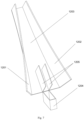
- the first side plate 1001 and the second side plate 1002 are mounted on the upper surface of the first inclined bottom plate 7, thereby forming a first chute 1005; the first inclined bottom plate 7 under the first side plate 1001 and the second side plate 1002 where the first chute 1005 is located is provided with a drop opening 1004, the turnover plate 1003 is connected to the lower surface of the inclined bottom plate and covers the drop opening 1004, and the size of the drop opening 1004 ensures the probe sampling area 2 to pass smoothly.
- the first chute 1005 is arranged as a structure that gradually becomes smaller, the minimum size of an outlet at the lower part of the first chute 1005 is greater than the maximum size of the two-piece mold housing component 3 and smaller than the cross-sectional diameter of the probe sampling area 2, so as to separate the paper housing of the probe sampling area 2 from the two-piece mold housing component 3 inside the paper housing.
- a drop opening 1004 is formed between the first side plate 1001 and the second side plate 1002, and an outlet of the first chute 1005 is formed between the lower end of the first side plate 1001 and the lower end of the second side plate 1002.
- the turnover plate 1003 is connected to the lower surface of the first inclined bottom plate 7 by an adjustable hinge 1006 and can cover the position of the drop opening 1004 (as shown in Fig. 5 ).
- the probe sampling area 2 which is laterally overturned with the open side facing gradually downwards, rushes into the first chute 1005 due to inertia, at this moment, there is no force between the probe sampling area 2 and the first inclined bottom plate 7.
- the open side of the probe sampling area 2 collides with the side plates at the outlet at the lower part of the first chute 1005, and the probe sampling area 2 intercepted in the first chute as its size cannot pass through the outlet of the first chute 1005; the sample 4 of the probe sampling area 2 and the two-piece mold housing component 3 can then continue to rush out of the outlet at the lower part of the first chute 1005.
- the paper housing of the probe sampling area 2 by its own gravity action, enables the turnover plate 1003 mounted to the lower surface of the first inclined bottom plate 7 to be overturned downward and passes through the drop opening 1004 to fall out of the separation device, so that the separation of the paper housing of the probe sampling area 2 from the sample 4 and the two-piece mold housing component 3 is completed.
- the heights of the first side plate 1001 and the second side plate 1002 should be at least greater than the cross-sectional radius of the probe sampling area 2, so as to prevent the probe sampling area 2 from being directly overturned out of the first side plate 1001 and the second side plate 1002 due to inertia.
- the second posture adjustment device 11 includes a second chute 1101 mounted on the upper surface of the second inclined bottom plate 8 and used for adjusting the postures of the sample 4 and the two-piece mold housing component 3.
- the inner wall of the second chute 1101 is arranged as a curved surface 1102 with varying angles, and an inlet 1103 of the second chute 1101 communicates with the outlet of the first chute 1005.
- the sample 4 and the two-piece mold housing component 3 sliding off from the first chute 1005 pass through the second chute 1101 to be adjusted stepwise from an arbitrary posture to a near upright state, i.e., a state of rolling along the side of the mold housing component 3, and enter the second separation device 12.
- the second separation device 12 includes a third side plate 1201 with an inclination angle and a fourth side plate 1202 with inclination angle, and a third chute 1203 is formed between the third side plate 1201 and the fourth side plate 1202.
- the third side plate 1201 and the fourth side plate 1202 are connected to the upper surface of the second inclined bottom plate 8, the upper ends of the third side plate 1201 and the fourth side plate 1202 are arranged facing the upper end of the inclined bottom plate, and the lower ends of the third side plate 1201 and the fourth side plate 1202 are arranged facing the lower end of the inclined bottom plate.
- the third side plate and the fourth side plate are gradually outwards overturned in the direction from the front end of the inclined bottom plate to the rear end (or the angles of inclination of the third side plate and the fourth side plate in opposite directions gradually increase).
- the distance between the third side plate 1201 and the fourth side plate 1202 gradually becomes larger from the front end to the rear end.
- An inlet of the third chute 1203 communicates with an outlet 1105 of the second chute 1101, and the size of the inlet of the third chute 1203 should be greater than the height of a cylinder formed when the two-piece mold housing component 3 is in the combined state and smaller than the diameter of the cylinder formed when the two-piece mold housing component 3 is in the combined state.
- the sample 4 is a standard flat cylinder, which is in an upright state when entering the second separation device 12, then rolls and slides along a straight line in the third chute 1203, and is always located at the centerline position of the third chute 1203, whereas due to having a chamfer, the two-piece mold housing component 3 gradually changes from an upright state to a state of rolling along the third side plate 1201 and the fourth side plate 1202 during sliding.
- the two-piece mold housing component 3 will gradually deviate from the centerline of the third chute 1203, and the distance between the two-piece mold housing component 3 and the sample 4 is larger and larger until the two-piece mold housing component 3 and the sample 4 are completely separated, then the sample 4 falls into a sample extraction area 1204 located at the outlet of the third chute 1203.
- the distance between the turnover collision point provided by the turnover collision point 902 and the constraining collision point provided by the constraining collision point 901 and the first inclined bottom plate 7 is not smaller than the radius of the end face of the probe sampling area 2; if the probe sampling area 2 is divided into left and right areas as shown in Fig. 4 with reference to an axial section perpendicular to the first inclined bottom plate 7, the turnover collision point and the constraint collision point should be located in the same area.
- the lower surface of the first inclined bottom plate 7 at the drop opening 1004 is provided with a downwards overturned turnover plate 1003 by means of an adjustable hinge 1006.
- the probe sampling area 2 which rushes into the first chute 1005 by inertia, collides with the outlet at the lower part of the first chute 1005. the sample 4 and the two-piece mold housing component 3 slide into the second chute from the outlet, and the paper housing of the probe sampling area 2 can overturn the turnover plate 1003 downwards by its own gravity, so as to fall out from the drop opening 1004 to complete the separation of the paper housing of the probe sampling area 2 from the sample 4 and the two-piece mold housing component 3.
- the opening and closing of the turnover plate 1003 can be controlled by means of an air cylinder. Furthermore, due to its own inertia, the probe sampling area 2 will not fall out of the drop opening 1004 since there is no force acting between the probe sampling area 2 and the first inclined bottom plate 7 before the probe sampling area 2 collides with the outlet of the first chute 1005, so that the turnover plate 1003 can be omitted in some embodiments.
- the inner wall of the second chute 1101 is set as a curved surface 1102 with varying angles, the curved surface 1102 is parallel to a bottom plate 1104 of the second chute 1101 at the inlet 1103 of the second chute 1101, and the curved surface 1102 is perpendicular to the bottom plate 1104 of the second chute 1101 at the outlet 1105 of the second chute 1101.
- FIG. 7 in which a first embodiment of the third chute 1203 is shown.
- Two partitioning plates 1205 are mounted on the inclined bottom plate at the outlet position of the third chute 1203.
- the sample extraction area 1204 is located at the end of the outlet position of the third chute 1203 and located between the two partitioning plates 1205.
- the sample 4 rolls and slides along a straight line on the centerline of the third chute 1203, slides into the channel between the two partitioning plates 1205 and falls into the sample extraction area 1204 below, whereas due to having a chamfer, the two-piece mold housing component 3 will roll against the third side plate 1201 and the fourth side plate 1202, slides into the channel between the partitioning plates 1205 and the third side plate 1201 and the channel between the partitioning plates 1205 and the fourth side plate 1202, and falls into a mold housing component collection area.
- FIG. 8 in which a second embodiment of the third chute 1203 is shown.
- the centerline of the inclined bottom plate at the outlet position of the third chute 1203 is provided with a rectangular opening 1206.
- the edge of the rectangular opening 1206 close to the sample extraction area 1204 i.e., the end of the rectangular opening
- the sample extraction area 1204 is located below the rectangular opening 1206.
- the sample 4 rolls and slides along a straight line on the centerline of the third chute 1203 and falls into the sample extraction area 1204 below from the rectangular opening 1206, whereas due to having a chamfer, the two-piece mold housing component 3 will roll against the third side plate 1201 and the fourth side plate 1202, slides out from the outlet of the third chute 1203 and falls into the housing component collection area.
- the present invention also provides a use method of the automatic separation device, including the following steps:
- the adjusting in step 5) specifically includes the following steps:
Landscapes
- Life Sciences & Earth Sciences (AREA)
- General Physics & Mathematics (AREA)
- Physics & Mathematics (AREA)
- Biochemistry (AREA)
- Chemical & Material Sciences (AREA)
- Analytical Chemistry (AREA)
- Health & Medical Sciences (AREA)
- General Health & Medical Sciences (AREA)
- Immunology (AREA)
- Pathology (AREA)
- Hydrology & Water Resources (AREA)
- Forests & Forestry (AREA)
- Engineering & Computer Science (AREA)
- Mechanical Engineering (AREA)
- Sampling And Sample Adjustment (AREA)
Claims (19)
- Automatische Trennvorrichtung für eine Probenahmesonde, die einen Sondenendbereich (1) und einen Sondenprobenahmebereich (2) umfasst, der mit einer Oberseite des Sondenendbereichs (1) verbunden ist, wobei der Sondenprobenahmebereich (2) ein Gehäuse umfasst, wobei eine zweiteilige Formgehäusekomponente (3) in dem Gehäuse angeordnet ist und eine Probe (4) innerhalb der zweiteiligen Formgehäusekomponente (3) angeordnet ist und wobei die zweiteilige Formgehäusekomponente (3) mit einem Klebeband umwickelt und befestigt ist, das brennbar und schmelzbar ist,die automatische Trennvorrichtung umfassend eine Schneidvorrichtung (5) zum Schneiden des Sondenprobenahmebereichs (2) in der Probenahmesonde und eine geneigte Bodenplatte (7,8),wobei die geneigte Bodenplatte (7, 8) vom vorderen Ende zum hinteren Ende nach unten geneigt ist, wobei sich das vordere Ende der geneigten Bodenplatte (7, 8) nahe an der Schneidvorrichtung (5) befindet und das hintere Ende der geneigten Bodenplatte (7, 8) von der Schneidvorrichtung (5) entfernt angeordnet ist,dadurch gekennzeichnet, dass eine erste Stellungseinstellvorrichtung (9), eine erste Trennvorrichtung (10), eine zweite Stellungseinstellvorrichtung (11) und eine zweite Trennvorrichtung (12) nacheinander zwischen dem vorderen Ende der geneigten Bodenplatte (7, 8) und dem hinteren Ende der geneigten Bodenplatte (7, 8) angeordnet sind und die erste Stellungseinstellvorrichtung (9), die erste Trennvorrichtung (10), die zweite Stellungseinstellvorrichtung (11) und die zweite Trennvorrichtung (12) auf der oberen Oberfläche der geneigten Bodenplatte (7, 8) montiert sind.
- Automatische Trennvorrichtung für eine Probenahmesonde gemäß Anspruch 1, wobei die erste Stellungseinstellvorrichtung (9) mindestens zwei Kollisionspunkte (901, 902) umfasst, die nacheinander in einer Richtung vom vorderen Ende der geneigten Bodenplatte (7, 8) zum hinteren Ende der geneigten Bodenplatte (7, 8) angeordnet sind und/oder
die Schneidvorrichtung (5) eine Schervorrichtung, eine Quetschvorrichtung oder eine Sägevorrichtung umfasst. - Automatische Trennvorrichtung für eine Probenahmesonde gemäß Anspruch 2, wobei die Kollisionspunkte einen Umkehrkollisionspunkt (902) und einen Einschränkungskollisionspunkt (901) umfassen, und wobei der Umkehrkollisionspunkt (902) zum Anliegen an die Endfläche des Sondenprobenahmebereichs (2) verwendet wird und der Einschränkungskollisionspunkt (901) zum Anliegen an die äußere Umfangsseite des Sondenprobenahmebereichs (2) verwendet wird.
- Automatische Trennvorrichtung für eine Probenahmesonde nach Anspruch 3, wobei der Abstand zwischen dem Umkehrkollisionspunkt (902) und dem Einschränkungskollisionspunkt (901) auf der Oberseite der geneigten Bodenplatte (7, 8) größer oder gleich dem Radius der Endfläche des Sondenprobenahmebereichs (2) ist.
- Automatische Trennvorrichtung für eine Probenahmesonde nach Anspruch 1, wobei die erste Trennvorrichtung (10) eine erste Seitenplatte (1001), eine zweite Seitenplatte (1002) und eine Umkehrplatte (1003) umfasst,die erste Seitenplatte (1001) und die zweite Seitenplatte (1002) mit der Oberseite der geneigten Bodenplatte (7, 8) verbunden sind und dadurch eine erste Rutsche (1005) bilden,die geneigte Bodenplatte (7, 8), die sich innerhalb der ersten Rutsche (1005) befindet, mit einer Fallöffnung (1004) versehen ist und die Umkehrplatte (1003) mit der Unterseite der geneigten Bodenplatte (7, 8) verbunden ist und die Fallöffnung (1004) abdeckt,die erste Rutsche (1005) ist als eine Struktur angeordnet ist, die in einer Richtung vom vorderen Ende hin zum hinteren Ende der geneigten Bodenplatte (7, 8) allmählich kleiner wird, und die Mindestgröße des Auslasses der ersten Rutsche (1005) größer ist als die Maximalgröße der zweiteiligen Formgehäusekomponente (3) und kleiner ist als der Querschnittsdurchmesser des Sondenprobenahmebereichs (2).
- Automatische Trennvorrichtung für eine Probennahmesonde nach Anspruch 5, wobei die Höhe der ersten Seitenplatte (1001) und die Höhe der zweiten Seitenplatte (1002) beide größer sind als der Querschnittsradius des Sondenprobenahmebereichs (2).
- Automatische Trennvorrichtung für eine Probenahmesonde nach Anspruch 5, wobei die zweite Stellungseinstellvorrichtung (11) eine zweite Rutsche (1101) umfasst und der Einlass (1103) der zweiten Rutsche (1101) mit dem Auslass der ersten Rutsche (1005) in Verbindung steht.
- Automatische Trennvorrichtung für eine Probenahmesonde nach Anspruch 7, wobei die innere Seitenwand der zweiten Rutsche (1101) als gekrümmte Oberfläche (1102) mit Winkeländerungen festgelegt ist.
- Automatische Trennvorrichtung für eine Probenahmesonde gemäß Anspruch 7, wobei die zweite Trennvorrichtung (12) eine dritte Seitenplatte (1201), eine vierte Seitenplatte (1202) und einen Probennahmebereich (1204) umfasst, wobeidie dritte Seitenplatte (1201) und die vierte Seitenplatte (1202) mit der oberen Oberfläche der geneigten Bodenplatte (7, 8) verbunden sind und dadurch eine dritte Rutsche (1203) bilden,der Einlass der dritten Rutsche (1203) mit dem Auslass (1105) der zweiten Rutsche (1101) in Verbindung steht,der Probennahmebereich (1204) an der unteren Position der dritten Rutsche (1203) angeordnet ist.
- Automatische Trennvorrichtung für eine Probenahmesonde nach Anspruch 9, wobei die dritte Rutsche (1203) als eine Struktur angeordnet ist, die in Richtung vom vorderen Ende hin zum hinteren Ende der geneigten Bodenplatte (7, 8) allmählich größer wird und die Neigungswinkel der dritten Seitenplatte (1201) und der vierten Seitenplatte (1202) in Richtung vom vorderen Ende hin zum hinteren Ende der geneigten Bodenplatte (7, 8) allmählich zunehmen.
- Automatische Trennvorrichtung für eine Probenahmesonde nach Anspruch 10, wobei die Größe des Einlasses der dritten Rutsche (1203) größer ist als die Höhe eines Zylinders, der gebildet wird, wenn sich die zweiteilige Formgehäusekomponente (3) in einem kombinierten Zustand befindet, und kleiner ist als der Durchmesser des Zylinders, der gebildet wird, wenn sich die zweiteilige Formgehäusekomponente (3) im kombinierten Zustand befindet.
- Automatische Trennvorrichtung für eine Probenahmesonde nach Anspruch 5, wobei die Umkehrplatte (1003) mittels eines verstellbaren Scharniers (1006) mit der Unterseite der geneigten Bodenplatte (7, 8) verbunden ist.
- Automatische Trennvorrichtung für eine Probenahmesonde nach Anspruch 9, wobei das untere Ende der dritten Rutsche (1203) des Weiteren mit einer Trennplatte (1205) versehen ist.
- Automatische Trennvorrichtung für eine Probenahmesonde nach Anspruch 9, wobei das untere Ende der dritten Rutsche (1203) mit einer rechteckigen Öffnung (1206) versehen ist und die rechteckige Öffnung (1206) an ihrer Kante in der Nähe des Probennahmebereichs (1204) mit einer Sperrplatte (1207) versehen ist.
- Automatische Trennvorrichtung für eine Probenahmesonde nach Anspruch 1, wobei die geneigte Bodenplatte eine erste geneigte Bodenplatte (7) und eine zweite geneigte Bodenplatte (8) umfasst, die mit dem hinteren Ende der ersten geneigten Bodenplatte (7) verbunden ist.
- Automatische Trennvorrichtung für eine Probenahmesonde nach Anspruch 1, wobei die geneigte Bodenplatte (7, 8) einen Neigungswinkel von 30° aufweist.
- Verfahren zur Verwendung basierend auf der automatischen Trennvorrichtung gemäß einem der Ansprüche 1 bis 16, umfassend die folgenden Schritte:1) Halten der axialen Mittellinie der Probenahmesonde senkrecht zur Wirkungsrichtung der Schneidvorrichtung (5),2) Messen und Einstellen einer Positionsbeziehung zwischen der Probenahmesonde und der Schneidvorrichtung (5) in Bezug auf ein Ende der Probenahmesonde und Markieren und Aufzeichnen der Position der Probenahmesonde nach der Einstellung,3) vorläufiges Bestimmen einer Montageposition der ersten Stellungseinstellvorrichtung (9) auf der geneigten Bodenplatte (7, 8) entsprechend der Position der von der Schneidvorrichtung (5) geschnittenen Probenahmesonde,4) Einstellen des Neigungswinkels der geneigten Bodenplatte,5) wiederholtes Schneiden mehrerer Probenahmesonden mit denselben Spezifikationen durch die Schneidvorrichtung (5) und Einstellen der ersten Trennvorrichtung (10), der zweiten Stellungseinstellvorrichtung (11) und der zweiten Trennvorrichtung (12) und6) Bestimmen einer endgültigen Montageposition, nachdem der Einstellschritt in Schritt 5) abgeschlossen ist, wodurch die automatische Trennvorrichtung erhalten wird.
- Verfahren zur Verwendung nach Anspruch 17, wobei das Einstellen in Schritt 5) insbesondere die folgenden Schritte umfasst:5.1) Beobachten einer Kollisionsposition des von der Probenahmesonde abgeschnittenen Sondenprobenahmebereichs (2), Einstellen der ersten Stellungseinstellvorrichtung (9) derart, dass sich der einschränkende Kollisionspunkt (901) auf der ersten Stellungseinstellvorrichtung (9) an der Seite des Sondenprobenbereichs (2) befindet, und anschließendes Feineinstellen der Position des einschränkenden Kollisionspunkts (901) auf der ersten Trennvorrichtung (10) entsprechend der Position des Sondenprobenahmebereichs (2), der mit der ersten Rutsche (1005) kollidiert,5.2) Öffnen der Fallöffnung (1004) und Beobachten der Trennung der zweiteiligen Formgehäusekomponente (3) und der Probe (4) in der Fallöffnung (1004) und5.3) Beobachten der Bewegungszustände der zweiteiligen Formgehäusekomponente (3) und der Probe (4) in der zweiten Stellungseinstellvorrichtung (11) und der zweiten Trennvorrichtung (12) und Einstellen der zweiten Stellungseinstellvorrichtung (11) und der zweiten Trennvorrichtung (12), bis die zweiteilige Formgehäusekomponente (3) und die Probe (4) erfolgreich von der dritten Rutsche (1203) getrennt sind.
- Verfahren zur Verwendung nach Anspruch 17, wobei die geneigte Bodenplatte (7, 8) einen Neigungswinkel von 30° aufweist.
Applications Claiming Priority (2)
| Application Number | Priority Date | Filing Date | Title |
|---|---|---|---|
| CN202110193177.8A CN114964894B (zh) | 2021-02-20 | 2021-02-20 | 一种取样探头及其自动分离设备、使用方法 |
| PCT/CN2022/076885 WO2022174819A1 (zh) | 2021-02-20 | 2022-02-18 | 一种取样探头及其自动分离设备、使用方法 |
Publications (3)
| Publication Number | Publication Date |
|---|---|
| EP4276439A1 EP4276439A1 (de) | 2023-11-15 |
| EP4276439A4 EP4276439A4 (de) | 2024-06-12 |
| EP4276439B1 true EP4276439B1 (de) | 2025-04-02 |
Family
ID=82931183
Family Applications (1)
| Application Number | Title | Priority Date | Filing Date |
|---|---|---|---|
| EP22755592.7A Active EP4276439B1 (de) | 2021-02-20 | 2022-02-18 | Automatische trennvorrichtung und verwendungsverfahren dafür |
Country Status (6)
| Country | Link |
|---|---|
| US (1) | US20240044751A1 (de) |
| EP (1) | EP4276439B1 (de) |
| JP (1) | JP7612034B2 (de) |
| KR (1) | KR20230129047A (de) |
| CN (1) | CN114964894B (de) |
| WO (1) | WO2022174819A1 (de) |
Families Citing this family (1)
| Publication number | Priority date | Publication date | Assignee | Title |
|---|---|---|---|---|
| CN116558921A (zh) * | 2023-05-17 | 2023-08-08 | 银川东方气力运输设备有限公司 | 炉前样品智能处理系统 |
Family Cites Families (27)
| Publication number | Priority date | Publication date | Assignee | Title |
|---|---|---|---|---|
| GB1426205A (en) * | 1973-05-16 | 1976-02-25 | Land Pyrometers Ltd | Sampling metal melts |
| US4037478A (en) * | 1976-09-15 | 1977-07-26 | Electro-Nite Co. | Device for collecting samples of molten metal |
| FR2389120A1 (fr) * | 1977-04-29 | 1978-11-24 | Electro Nite | Dispositif de prelevement d'echantillons de metal en fusion |
| CA1131049A (en) * | 1977-11-28 | 1982-09-07 | William J. Collins | Molten material sampler |
| GB1579952A (en) * | 1978-05-15 | 1980-11-26 | Amalgams Co Ltd | Molten metal sampling |
| US4250754A (en) * | 1979-05-09 | 1981-02-17 | Collins William J | Sampler for a hot liquid and connector therefor |
| US4380937A (en) * | 1981-04-13 | 1983-04-26 | Collins William J | Sampler for a hot liquid |
| JPS59109838A (ja) * | 1982-12-16 | 1984-06-25 | Suzuki Giken Kogyo Kk | サンプルの自動取出し装置 |
| US4499777A (en) * | 1983-03-03 | 1985-02-19 | Haly, Inc. | Molten metal samplers |
| DE3418320A1 (de) * | 1983-05-20 | 1984-11-29 | Electro-Nite, N.V., Houthalen | Probeheber fuer fluessiges metall und dabei angewandte klemme |
| ATA51086A (de) * | 1986-02-27 | 1990-08-15 | Voest Alpine Ag | Verfahren zum gewinnen einer probe aus einem schmelzensumpf mittels einer probenahmesonde sowie vorrichtung zur durchfuehrung des verfahrens |
| JPH0383866U (de) * | 1989-12-18 | 1991-08-26 | ||
| JPH0621285B2 (ja) * | 1990-07-20 | 1994-03-23 | 奥村機械製作株式会社 | 溶融金属炉におけるサンプルの自動サンプリング・姿勢修正移送方法 |
| JPH0816594B2 (ja) * | 1991-12-13 | 1996-02-21 | 新日本製鐵株式会社 | プローブからの溶融金属サンプル取出装置 |
| JP2593760B2 (ja) * | 1992-03-09 | 1997-03-26 | 新日本製鐵株式会社 | サンプル分析装置 |
| JP2586634Y2 (ja) * | 1993-03-31 | 1998-12-09 | 日本ミンコ株式会社 | 溶融金属試料採取プローブ |
| DE19654522C2 (de) * | 1996-12-19 | 1999-05-12 | Mannesmann Ag | Einrichtung zum Entfernen von Proben aus einer Meßsonde |
| CN2511960Y (zh) * | 2001-10-26 | 2002-09-18 | 陈健 | 钢液取样复合探头 |
| KR101321333B1 (ko) * | 2011-12-16 | 2013-10-23 | 주식회사 우진 | 폐프로브 파쇄장치 |
| EP2626685A1 (de) * | 2012-02-08 | 2013-08-14 | Siemens VAI Metals Technologies GmbH | Verfahren und Vorrichtung zur automatisierten Freilegung von Probenkörpern |
| CN104359710B (zh) * | 2014-11-13 | 2017-04-05 | 东北大学 | 一种自动脱模钢水取样器及其使用方法 |
| EP3614121A1 (de) * | 2018-08-22 | 2020-02-26 | Primetals Technologies Austria GmbH | Entnehmen einer metallischen probe aus einer probensonde |
| CN111426528B (zh) * | 2019-01-10 | 2022-12-16 | 宝山钢铁股份有限公司 | 一种用于取样探头自动分离金属样品体的分离设备及其方法 |
| CN111426529B (zh) | 2019-01-10 | 2023-01-20 | 宝山钢铁股份有限公司 | 一种自动分离取样探头中金属样品体的设备及其分离方法 |
| CN109900514B (zh) * | 2019-04-18 | 2020-10-20 | 吉林大学 | 一种用于粘接结构老化性能试验的胶条试样取样装置及取样方法和胶条预埋位置优化方法 |
| CN110231195B (zh) * | 2019-04-22 | 2022-05-13 | 中冶南方工程技术有限公司 | 一种冶金取样探头样本自动分离及装样装置 |
| CN212780069U (zh) * | 2020-07-13 | 2021-03-23 | 马鞍山江润冶金有限责任公司 | 一种金属冶炼用取样器 |
-
2021
- 2021-02-20 CN CN202110193177.8A patent/CN114964894B/zh active Active
-
2022
- 2022-02-18 KR KR1020237027288A patent/KR20230129047A/ko active Pending
- 2022-02-18 JP JP2023548969A patent/JP7612034B2/ja active Active
- 2022-02-18 EP EP22755592.7A patent/EP4276439B1/de active Active
- 2022-02-18 WO PCT/CN2022/076885 patent/WO2022174819A1/zh not_active Ceased
- 2022-02-18 US US18/546,494 patent/US20240044751A1/en active Pending
Also Published As
| Publication number | Publication date |
|---|---|
| KR20230129047A (ko) | 2023-09-05 |
| EP4276439A4 (de) | 2024-06-12 |
| EP4276439A1 (de) | 2023-11-15 |
| US20240044751A1 (en) | 2024-02-08 |
| WO2022174819A1 (zh) | 2022-08-25 |
| JP2024506922A (ja) | 2024-02-15 |
| CN114964894A (zh) | 2022-08-30 |
| JP7612034B2 (ja) | 2025-01-10 |
| CN114964894B (zh) | 2024-12-10 |
Similar Documents
| Publication | Publication Date | Title |
|---|---|---|
| EP4276439A1 (de) | Probenahmesonde und automatische trennvorrichtung dafür sowie verwendungsverfahren | |
| May | An “ultimate” cascade impactor for aerosol assessment | |
| CN106969944B (zh) | 一种螺旋采样装置 | |
| JP7710097B2 (ja) | 冶金測温サンプリングプローブの交換システム及び交換方法 | |
| CN216621823U (zh) | 一种环境监测土壤取样器 | |
| CN113909139A (zh) | 一种自动称重分料装置 | |
| CN114354257A (zh) | 水泥窑热生料自动取样及在线检测系统和在线检测方法 | |
| CN110002244B (zh) | 碗型塞尺寸自动检测装置 | |
| CN221992409U (zh) | 一种试样进出可靠性高的管式炉 | |
| JP4494407B2 (ja) | 粉末を抽出するためのデバイス | |
| CN213737165U (zh) | 一种高效的振动盘 | |
| CN114814151A (zh) | 一种硬质合金圆棒缺陷自动检测装置及其检测方法 | |
| CN112893173B (zh) | 一种毛细钢管自动分拣系统 | |
| JPH0528509Y2 (de) | ||
| CN210347225U (zh) | 一种新型医学检验微量取样器 | |
| CN223700181U (zh) | 一种金属加工碎屑收集分离装置 | |
| CN221993068U (zh) | 一种工程检测取样装置 | |
| JPS6039800Y2 (ja) | 試料採取具 | |
| CN221563709U (zh) | 一种缓存式自动下料装置 | |
| CN223295686U (zh) | 一种具有接料装置的球团取样机 | |
| JPH0816595B2 (ja) | 溶融金属サンプル採取室の自動位置決め切断装置 | |
| CN217385206U (zh) | 一种高频红外碳硫分析系统 | |
| CN221764950U (zh) | 一种用于烟草制丝线储丝柜的烟丝取样器 | |
| CN216594307U (zh) | 混凝土性能研究用取样装置 | |
| CN120253629A (zh) | 一种沙通量监测系统及监测方法 |
Legal Events
| Date | Code | Title | Description |
|---|---|---|---|
| STAA | Information on the status of an ep patent application or granted ep patent |
Free format text: STATUS: THE INTERNATIONAL PUBLICATION HAS BEEN MADE |
|
| PUAI | Public reference made under article 153(3) epc to a published international application that has entered the european phase |
Free format text: ORIGINAL CODE: 0009012 |
|
| STAA | Information on the status of an ep patent application or granted ep patent |
Free format text: STATUS: REQUEST FOR EXAMINATION WAS MADE |
|
| 17P | Request for examination filed |
Effective date: 20230808 |
|
| AK | Designated contracting states |
Kind code of ref document: A1 Designated state(s): AL AT BE BG CH CY CZ DE DK EE ES FI FR GB GR HR HU IE IS IT LI LT LU LV MC MK MT NL NO PL PT RO RS SE SI SK SM TR |
|
| DAV | Request for validation of the european patent (deleted) | ||
| DAX | Request for extension of the european patent (deleted) | ||
| A4 | Supplementary search report drawn up and despatched |
Effective date: 20240514 |
|
| RIC1 | Information provided on ipc code assigned before grant |
Ipc: G01N 1/28 20060101ALI20240507BHEP Ipc: G01N 1/12 20060101ALI20240507BHEP Ipc: B26D 7/00 20060101ALI20240507BHEP Ipc: G01K 13/12 20060101ALI20240507BHEP Ipc: G01N 1/10 20060101AFI20240507BHEP |
|
| GRAP | Despatch of communication of intention to grant a patent |
Free format text: ORIGINAL CODE: EPIDOSNIGR1 |
|
| STAA | Information on the status of an ep patent application or granted ep patent |
Free format text: STATUS: GRANT OF PATENT IS INTENDED |
|
| INTG | Intention to grant announced |
Effective date: 20241024 |
|
| P01 | Opt-out of the competence of the unified patent court (upc) registered |
Free format text: CASE NUMBER: APP_651/2025 Effective date: 20250108 |
|
| GRAS | Grant fee paid |
Free format text: ORIGINAL CODE: EPIDOSNIGR3 |
|
| GRAA | (expected) grant |
Free format text: ORIGINAL CODE: 0009210 |
|
| STAA | Information on the status of an ep patent application or granted ep patent |
Free format text: STATUS: THE PATENT HAS BEEN GRANTED |
|
| AK | Designated contracting states |
Kind code of ref document: B1 Designated state(s): AL AT BE BG CH CY CZ DE DK EE ES FI FR GB GR HR HU IE IS IT LI LT LU LV MC MK MT NL NO PL PT RO RS SE SI SK SM TR |
|
| REG | Reference to a national code |
Ref country code: GB Ref legal event code: FG4D |
|
| REG | Reference to a national code |
Ref country code: CH Ref legal event code: EP |
|
| REG | Reference to a national code |
Ref country code: IE Ref legal event code: FG4D |
|
| REG | Reference to a national code |
Ref country code: DE Ref legal event code: R096 Ref document number: 602022012670 Country of ref document: DE |
|
| REG | Reference to a national code |
Ref country code: NL Ref legal event code: MP Effective date: 20250402 |
|
| PG25 | Lapsed in a contracting state [announced via postgrant information from national office to epo] |
Ref country code: NL Free format text: LAPSE BECAUSE OF FAILURE TO SUBMIT A TRANSLATION OF THE DESCRIPTION OR TO PAY THE FEE WITHIN THE PRESCRIBED TIME-LIMIT Effective date: 20250402 |
|
| PG25 | Lapsed in a contracting state [announced via postgrant information from national office to epo] |
Ref country code: PT Free format text: LAPSE BECAUSE OF FAILURE TO SUBMIT A TRANSLATION OF THE DESCRIPTION OR TO PAY THE FEE WITHIN THE PRESCRIBED TIME-LIMIT Effective date: 20250804 Ref country code: FI Free format text: LAPSE BECAUSE OF FAILURE TO SUBMIT A TRANSLATION OF THE DESCRIPTION OR TO PAY THE FEE WITHIN THE PRESCRIBED TIME-LIMIT Effective date: 20250402 Ref country code: ES Free format text: LAPSE BECAUSE OF FAILURE TO SUBMIT A TRANSLATION OF THE DESCRIPTION OR TO PAY THE FEE WITHIN THE PRESCRIBED TIME-LIMIT Effective date: 20250402 |
|
| REG | Reference to a national code |
Ref country code: LT Ref legal event code: MG9D |
|
| PG25 | Lapsed in a contracting state [announced via postgrant information from national office to epo] |
Ref country code: NO Free format text: LAPSE BECAUSE OF FAILURE TO SUBMIT A TRANSLATION OF THE DESCRIPTION OR TO PAY THE FEE WITHIN THE PRESCRIBED TIME-LIMIT Effective date: 20250702 Ref country code: GR Free format text: LAPSE BECAUSE OF FAILURE TO SUBMIT A TRANSLATION OF THE DESCRIPTION OR TO PAY THE FEE WITHIN THE PRESCRIBED TIME-LIMIT Effective date: 20250703 |
|
| PG25 | Lapsed in a contracting state [announced via postgrant information from national office to epo] |
Ref country code: PL Free format text: LAPSE BECAUSE OF FAILURE TO SUBMIT A TRANSLATION OF THE DESCRIPTION OR TO PAY THE FEE WITHIN THE PRESCRIBED TIME-LIMIT Effective date: 20250402 |
|
| PG25 | Lapsed in a contracting state [announced via postgrant information from national office to epo] |
Ref country code: BG Free format text: LAPSE BECAUSE OF FAILURE TO SUBMIT A TRANSLATION OF THE DESCRIPTION OR TO PAY THE FEE WITHIN THE PRESCRIBED TIME-LIMIT Effective date: 20250402 |
|
| PG25 | Lapsed in a contracting state [announced via postgrant information from national office to epo] |
Ref country code: HR Free format text: LAPSE BECAUSE OF FAILURE TO SUBMIT A TRANSLATION OF THE DESCRIPTION OR TO PAY THE FEE WITHIN THE PRESCRIBED TIME-LIMIT Effective date: 20250402 |
|
| PG25 | Lapsed in a contracting state [announced via postgrant information from national office to epo] |
Ref country code: RS Free format text: LAPSE BECAUSE OF FAILURE TO SUBMIT A TRANSLATION OF THE DESCRIPTION OR TO PAY THE FEE WITHIN THE PRESCRIBED TIME-LIMIT Effective date: 20250702 |
|
| PG25 | Lapsed in a contracting state [announced via postgrant information from national office to epo] |
Ref country code: IS Free format text: LAPSE BECAUSE OF FAILURE TO SUBMIT A TRANSLATION OF THE DESCRIPTION OR TO PAY THE FEE WITHIN THE PRESCRIBED TIME-LIMIT Effective date: 20250802 |
|
| PG25 | Lapsed in a contracting state [announced via postgrant information from national office to epo] |
Ref country code: LV Free format text: LAPSE BECAUSE OF FAILURE TO SUBMIT A TRANSLATION OF THE DESCRIPTION OR TO PAY THE FEE WITHIN THE PRESCRIBED TIME-LIMIT Effective date: 20250402 |
|
| REG | Reference to a national code |
Ref country code: DE Ref legal event code: R097 Ref document number: 602022012670 Country of ref document: DE |
|
| PG25 | Lapsed in a contracting state [announced via postgrant information from national office to epo] |
Ref country code: SM Free format text: LAPSE BECAUSE OF FAILURE TO SUBMIT A TRANSLATION OF THE DESCRIPTION OR TO PAY THE FEE WITHIN THE PRESCRIBED TIME-LIMIT Effective date: 20250402 Ref country code: DK Free format text: LAPSE BECAUSE OF FAILURE TO SUBMIT A TRANSLATION OF THE DESCRIPTION OR TO PAY THE FEE WITHIN THE PRESCRIBED TIME-LIMIT Effective date: 20250402 |
|
| PG25 | Lapsed in a contracting state [announced via postgrant information from national office to epo] |
Ref country code: CZ Free format text: LAPSE BECAUSE OF FAILURE TO SUBMIT A TRANSLATION OF THE DESCRIPTION OR TO PAY THE FEE WITHIN THE PRESCRIBED TIME-LIMIT Effective date: 20250402 |
|
| PG25 | Lapsed in a contracting state [announced via postgrant information from national office to epo] |
Ref country code: EE Free format text: LAPSE BECAUSE OF FAILURE TO SUBMIT A TRANSLATION OF THE DESCRIPTION OR TO PAY THE FEE WITHIN THE PRESCRIBED TIME-LIMIT Effective date: 20250402 |
|
| PG25 | Lapsed in a contracting state [announced via postgrant information from national office to epo] |
Ref country code: SK Free format text: LAPSE BECAUSE OF FAILURE TO SUBMIT A TRANSLATION OF THE DESCRIPTION OR TO PAY THE FEE WITHIN THE PRESCRIBED TIME-LIMIT Effective date: 20250402 |
|
| PG25 | Lapsed in a contracting state [announced via postgrant information from national office to epo] |
Ref country code: IT Free format text: LAPSE BECAUSE OF FAILURE TO SUBMIT A TRANSLATION OF THE DESCRIPTION OR TO PAY THE FEE WITHIN THE PRESCRIBED TIME-LIMIT Effective date: 20250402 |
|
| PLBE | No opposition filed within time limit |
Free format text: ORIGINAL CODE: 0009261 |
|
| STAA | Information on the status of an ep patent application or granted ep patent |
Free format text: STATUS: NO OPPOSITION FILED WITHIN TIME LIMIT |
|
| REG | Reference to a national code |
Ref country code: CH Ref legal event code: L10 Free format text: ST27 STATUS EVENT CODE: U-0-0-L10-L00 (AS PROVIDED BY THE NATIONAL OFFICE) Effective date: 20260211 |
|
| PGFP | Annual fee paid to national office [announced via postgrant information from national office to epo] |
Ref country code: LU Payment date: 20260127 Year of fee payment: 5 |
|
| 26N | No opposition filed |
Effective date: 20260105 |
|
| PGFP | Annual fee paid to national office [announced via postgrant information from national office to epo] |
Ref country code: DE Payment date: 20260206 Year of fee payment: 5 |
|
| PGFP | Annual fee paid to national office [announced via postgrant information from national office to epo] |
Ref country code: AT Payment date: 20260301 Year of fee payment: 5 |