EP4276256A2 - Système de montage de toit sans rail - Google Patents
Système de montage de toit sans rail Download PDFInfo
- Publication number
- EP4276256A2 EP4276256A2 EP23177830.9A EP23177830A EP4276256A2 EP 4276256 A2 EP4276256 A2 EP 4276256A2 EP 23177830 A EP23177830 A EP 23177830A EP 4276256 A2 EP4276256 A2 EP 4276256A2
- Authority
- EP
- European Patent Office
- Prior art keywords
- mounting system
- rail
- modules
- slider
- roof
- Prior art date
- Legal status (The legal status is an assumption and is not a legal conclusion. Google has not performed a legal analysis and makes no representation as to the accuracy of the status listed.)
- Pending
Links
- 230000000712 assembly Effects 0.000 claims 4
- 238000000429 assembly Methods 0.000 claims 4
- 238000007789 sealing Methods 0.000 abstract description 10
- 238000004078 waterproofing Methods 0.000 abstract description 6
- XLYOFNOQVPJJNP-UHFFFAOYSA-N water Substances O XLYOFNOQVPJJNP-UHFFFAOYSA-N 0.000 abstract description 3
- 230000037431 insertion Effects 0.000 abstract 1
- 238000003780 insertion Methods 0.000 abstract 1
- 230000008878 coupling Effects 0.000 description 24
- 238000010168 coupling process Methods 0.000 description 24
- 238000005859 coupling reaction Methods 0.000 description 24
- 238000009434 installation Methods 0.000 description 19
- 239000000463 material Substances 0.000 description 9
- 238000000034 method Methods 0.000 description 8
- 230000035515 penetration Effects 0.000 description 5
- 229910052782 aluminium Inorganic materials 0.000 description 3
- XAGFODPZIPBFFR-UHFFFAOYSA-N aluminium Chemical compound [Al] XAGFODPZIPBFFR-UHFFFAOYSA-N 0.000 description 3
- 230000009467 reduction Effects 0.000 description 3
- 229910000760 Hardened steel Inorganic materials 0.000 description 2
- 239000004411 aluminium Substances 0.000 description 2
- 230000008901 benefit Effects 0.000 description 2
- 239000011248 coating agent Substances 0.000 description 2
- 238000000576 coating method Methods 0.000 description 2
- 238000001125 extrusion Methods 0.000 description 2
- 229910052751 metal Inorganic materials 0.000 description 2
- 239000002184 metal Substances 0.000 description 2
- 229910000831 Steel Inorganic materials 0.000 description 1
- 230000000903 blocking effect Effects 0.000 description 1
- 230000008859 change Effects 0.000 description 1
- 238000010276 construction Methods 0.000 description 1
- 239000002537 cosmetic Substances 0.000 description 1
- 230000003247 decreasing effect Effects 0.000 description 1
- 230000002950 deficient Effects 0.000 description 1
- 229920001971 elastomer Polymers 0.000 description 1
- 238000010616 electrical installation Methods 0.000 description 1
- 230000005611 electricity Effects 0.000 description 1
- 238000009432 framing Methods 0.000 description 1
- 239000011521 glass Substances 0.000 description 1
- 238000012423 maintenance Methods 0.000 description 1
- 239000011159 matrix material Substances 0.000 description 1
- 239000000203 mixture Substances 0.000 description 1
- 238000012986 modification Methods 0.000 description 1
- 230000004048 modification Effects 0.000 description 1
- 239000004033 plastic Substances 0.000 description 1
- 229920003023 plastic Polymers 0.000 description 1
- 229920001296 polysiloxane Polymers 0.000 description 1
- 229920002635 polyurethane Polymers 0.000 description 1
- 239000004814 polyurethane Substances 0.000 description 1
- 238000007665 sagging Methods 0.000 description 1
- 229910001220 stainless steel Inorganic materials 0.000 description 1
- 239000010935 stainless steel Substances 0.000 description 1
- 239000010959 steel Substances 0.000 description 1
Images


Classifications
-
- H—ELECTRICITY
- H02—GENERATION; CONVERSION OR DISTRIBUTION OF ELECTRIC POWER
- H02S—GENERATION OF ELECTRIC POWER BY CONVERSION OF INFRARED RADIATION, VISIBLE LIGHT OR ULTRAVIOLET LIGHT, e.g. USING PHOTOVOLTAIC [PV] MODULES
- H02S20/00—Supporting structures for PV modules
- H02S20/20—Supporting structures directly fixed to an immovable object
- H02S20/22—Supporting structures directly fixed to an immovable object specially adapted for buildings
- H02S20/23—Supporting structures directly fixed to an immovable object specially adapted for buildings specially adapted for roof structures
-
- F—MECHANICAL ENGINEERING; LIGHTING; HEATING; WEAPONS; BLASTING
- F24—HEATING; RANGES; VENTILATING
- F24S—SOLAR HEAT COLLECTORS; SOLAR HEAT SYSTEMS
- F24S25/00—Arrangement of stationary mountings or supports for solar heat collector modules
- F24S25/30—Arrangement of stationary mountings or supports for solar heat collector modules using elongate rigid mounting elements extending substantially along the supporting surface, e.g. for covering buildings with solar heat collectors
- F24S25/33—Arrangement of stationary mountings or supports for solar heat collector modules using elongate rigid mounting elements extending substantially along the supporting surface, e.g. for covering buildings with solar heat collectors forming substantially planar assemblies, e.g. of coplanar or stacked profiles
-
- F—MECHANICAL ENGINEERING; LIGHTING; HEATING; WEAPONS; BLASTING
- F24—HEATING; RANGES; VENTILATING
- F24S—SOLAR HEAT COLLECTORS; SOLAR HEAT SYSTEMS
- F24S25/00—Arrangement of stationary mountings or supports for solar heat collector modules
- F24S25/60—Fixation means, e.g. fasteners, specially adapted for supporting solar heat collector modules
- F24S25/61—Fixation means, e.g. fasteners, specially adapted for supporting solar heat collector modules for fixing to the ground or to building structures
-
- F—MECHANICAL ENGINEERING; LIGHTING; HEATING; WEAPONS; BLASTING
- F24—HEATING; RANGES; VENTILATING
- F24S—SOLAR HEAT COLLECTORS; SOLAR HEAT SYSTEMS
- F24S25/00—Arrangement of stationary mountings or supports for solar heat collector modules
- F24S25/60—Fixation means, e.g. fasteners, specially adapted for supporting solar heat collector modules
- F24S25/63—Fixation means, e.g. fasteners, specially adapted for supporting solar heat collector modules for fixing modules or their peripheral frames to supporting elements
- F24S25/634—Clamps; Clips
- F24S25/636—Clamps; Clips clamping by screw-threaded elements
-
- F—MECHANICAL ENGINEERING; LIGHTING; HEATING; WEAPONS; BLASTING
- F24—HEATING; RANGES; VENTILATING
- F24S—SOLAR HEAT COLLECTORS; SOLAR HEAT SYSTEMS
- F24S25/00—Arrangement of stationary mountings or supports for solar heat collector modules
- F24S25/70—Arrangement of stationary mountings or supports for solar heat collector modules with means for adjusting the final position or orientation of supporting elements in relation to each other or to a mounting surface; with means for compensating mounting tolerances
-
- F—MECHANICAL ENGINEERING; LIGHTING; HEATING; WEAPONS; BLASTING
- F24—HEATING; RANGES; VENTILATING
- F24S—SOLAR HEAT COLLECTORS; SOLAR HEAT SYSTEMS
- F24S25/00—Arrangement of stationary mountings or supports for solar heat collector modules
- F24S25/60—Fixation means, e.g. fasteners, specially adapted for supporting solar heat collector modules
- F24S2025/6008—Fixation means, e.g. fasteners, specially adapted for supporting solar heat collector modules by using toothed elements
-
- F—MECHANICAL ENGINEERING; LIGHTING; HEATING; WEAPONS; BLASTING
- F24—HEATING; RANGES; VENTILATING
- F24S—SOLAR HEAT COLLECTORS; SOLAR HEAT SYSTEMS
- F24S25/00—Arrangement of stationary mountings or supports for solar heat collector modules
- F24S2025/80—Special profiles
- F24S2025/803—Special profiles having a central web, e.g. I-shaped, inverted T- shaped
-
- F—MECHANICAL ENGINEERING; LIGHTING; HEATING; WEAPONS; BLASTING
- F24—HEATING; RANGES; VENTILATING
- F24S—SOLAR HEAT COLLECTORS; SOLAR HEAT SYSTEMS
- F24S25/00—Arrangement of stationary mountings or supports for solar heat collector modules
- F24S2025/80—Special profiles
- F24S2025/807—Special profiles having undercut grooves
-
- Y—GENERAL TAGGING OF NEW TECHNOLOGICAL DEVELOPMENTS; GENERAL TAGGING OF CROSS-SECTIONAL TECHNOLOGIES SPANNING OVER SEVERAL SECTIONS OF THE IPC; TECHNICAL SUBJECTS COVERED BY FORMER USPC CROSS-REFERENCE ART COLLECTIONS [XRACs] AND DIGESTS
- Y02—TECHNOLOGIES OR APPLICATIONS FOR MITIGATION OR ADAPTATION AGAINST CLIMATE CHANGE
- Y02B—CLIMATE CHANGE MITIGATION TECHNOLOGIES RELATED TO BUILDINGS, e.g. HOUSING, HOUSE APPLIANCES OR RELATED END-USER APPLICATIONS
- Y02B10/00—Integration of renewable energy sources in buildings
- Y02B10/10—Photovoltaic [PV]
-
- Y—GENERAL TAGGING OF NEW TECHNOLOGICAL DEVELOPMENTS; GENERAL TAGGING OF CROSS-SECTIONAL TECHNOLOGIES SPANNING OVER SEVERAL SECTIONS OF THE IPC; TECHNICAL SUBJECTS COVERED BY FORMER USPC CROSS-REFERENCE ART COLLECTIONS [XRACs] AND DIGESTS
- Y02—TECHNOLOGIES OR APPLICATIONS FOR MITIGATION OR ADAPTATION AGAINST CLIMATE CHANGE
- Y02B—CLIMATE CHANGE MITIGATION TECHNOLOGIES RELATED TO BUILDINGS, e.g. HOUSING, HOUSE APPLIANCES OR RELATED END-USER APPLICATIONS
- Y02B10/00—Integration of renewable energy sources in buildings
- Y02B10/20—Solar thermal
-
- Y—GENERAL TAGGING OF NEW TECHNOLOGICAL DEVELOPMENTS; GENERAL TAGGING OF CROSS-SECTIONAL TECHNOLOGIES SPANNING OVER SEVERAL SECTIONS OF THE IPC; TECHNICAL SUBJECTS COVERED BY FORMER USPC CROSS-REFERENCE ART COLLECTIONS [XRACs] AND DIGESTS
- Y02—TECHNOLOGIES OR APPLICATIONS FOR MITIGATION OR ADAPTATION AGAINST CLIMATE CHANGE
- Y02E—REDUCTION OF GREENHOUSE GAS [GHG] EMISSIONS, RELATED TO ENERGY GENERATION, TRANSMISSION OR DISTRIBUTION
- Y02E10/00—Energy generation through renewable energy sources
- Y02E10/40—Solar thermal energy, e.g. solar towers
- Y02E10/47—Mountings or tracking
-
- Y—GENERAL TAGGING OF NEW TECHNOLOGICAL DEVELOPMENTS; GENERAL TAGGING OF CROSS-SECTIONAL TECHNOLOGIES SPANNING OVER SEVERAL SECTIONS OF THE IPC; TECHNICAL SUBJECTS COVERED BY FORMER USPC CROSS-REFERENCE ART COLLECTIONS [XRACs] AND DIGESTS
- Y02—TECHNOLOGIES OR APPLICATIONS FOR MITIGATION OR ADAPTATION AGAINST CLIMATE CHANGE
- Y02E—REDUCTION OF GREENHOUSE GAS [GHG] EMISSIONS, RELATED TO ENERGY GENERATION, TRANSMISSION OR DISTRIBUTION
- Y02E10/00—Energy generation through renewable energy sources
- Y02E10/50—Photovoltaic [PV] energy
Definitions
- the present embodiment relates in general to mounting systems for photovoltaic (PV) modules on roof structures. More specifically, the present disclosure relates to a rail-less photovoltaic (PV) module mounting system for providing a cost-effective means to install a plurality of photovoltaic (PV) modules on a roof structure.
- PV photovoltaic
- PV photovoltaic
- Traditional rail mounting systems require 5 penetrations per mount, 4 mounts per PV module, additional grounding lugs, and requires specifically engineered PV modules.
- existing rail mounting systems may have substandard waterproofing for roof penetrations, along with complex grounding, wire management, and increased labor time on the roof structure due to design flaws.
- Hard and soft balance of system (BOS) may include bypass diodes, blocking diodes, solar controller, wiring system, battery and/or inverter etc.
- the hard and soft balance of system (BOS) costs for PV rail mounting system are high due to high material costs as well as long system engineering and installation times.
- the traditional rail mounting systems require long strings that are difficult to break up, causing difficulty in working around roof obstructions (e.g. vents, skylights).
- the system comprises a plurality of solar modules and a plurality of splices for coupling the plurality of solar modules together.
- the plurality of splices provide a way to make the connected modules mechanically rigid both during transport to the roof and after mounting for the lifetime of the system; provide wiring connections between modules; provide an electrical grounding path for the modules; provide a way to add modules to the panel; and provide a way to remove or change a defective module.
- Connector sockets are provided on the sides of the PV modules to simplify the electrical assembly when the PV modules are connected together with splices.
- the frame of the PV module is installed with a groove to attach the mounting bracket and a hole to insert the splice to connect the PV modules, which results in a labor-intensive operation.
- it requires one mounting bracket per PV module and multiple holes in the roof structure are required for installation, increasing the risk of leaks.
- PV photovoltaic
- the system may further provide a rotating portion and locking portion for coupling to the frame attachment, mounting brackets for direct connection to a mounting surface, grounding teeth for the automatic creation of a reliable two axis grounding matrix, and a rapid twist-lock engagement means for reliably interlocking and aligning PV modules in the array.
- this embodiment includes a side-to-side arrangement to form an array and an additional groove/slot is formed on the frame to engage coupling member, which enables the interconnection of frames of adjacent PV modules.
- the parallel couplings are extended beyond corner regions of PV modules.
- a rail-less roof mounting system that would provide a cost effective and improved means for PV module installations.
- Such a rail-less roof mounting system would provide an efficient means of installation that does not require any additional material or structure to support the rail-less roof mounting system.
- Such a rail-less roof mounting system would provide a corner-to-corner coupling arrangement enabling the bridging of a PV module corner directly with adjacent PV module corner.
- Such a needed device would provide reduced shipping and hardware costs, labor and installation time and cost; reduce the dead load on the roof structure along with design engineering costs; and hard and soft balance of system (BOS) cost.
- This rail-less roof mounting system would provide a single grounding lug and a single point of penetration with an elevated seal portion for waterproofing the roof structure.
- Such a rail-less roof mounting system would typically be designed for implementation on composition shingle roofs, tile roofs, metal roofs, low slope roofs, or any roof that would benefit from being waterproof.
- This mounting system would also provide simple grounding, wire management, and structural quality.
- This system would be simple, inexpensive, and lightweight. This system would provide an improved engineering design to accommodate high snow and wind loads. Further, this rail-less roof mounting system would allow an installer to easily work around roof obstructions like vents, skylights, and other roof protrusions. This system would also minimize the number of parts and tools needed to assemble and install the PV module.
- This rail-less roof mounting system would provide the ability to increase vertical leveling adjustability; to independently remove a single PV module without deconstructing an entire row of the PV array; and allow for easy mounting height adjustment after PV modules are installed. Finally, this rail-less roof mounting system would require less manpower to install and rework.
- the rail-less roof mounting system comprises a base mount assembly attached to the roof structure.
- the base mount assembly includes a base member having a top surface and a bottom surface, a block slider having an elevated seal portion and a vertical engaging portion, and a top slider having a top portion and a bottom portion, and a clamp assembly having a clamp member and a plate member.
- the top surface of the base member is attached with a waterproof means and the bottom surface of the base member is engaged with the roof structure.
- the elevated seal portion having a borehole formed therethrough to receive the waterproof means, engages with the base member and the roof structure, utilizing at least one tightening means that is inserted through the borehole.
- the vertical engaging portion has a vertical groove along a surface thereof.
- the top slider having a track with a horizontal groove at the top portion and a sliding seal member with a sliding groove and a slot at the bottom portion.
- the sliding seal member slides over the vertical engaging portion through the sliding groove and secures, utilizing at least one fastening means that inserts through the vertical groove on the vertical engaging portion.
- the base mount assembly further includes a covering means that is adaptable to securely cover the at least one tightening means on the elevated seal portion for providing waterproof sealing between the base mount assembly and the roof structure.
- the clamp assembly comprises the clamp member that is coupled with the plate member.
- the clamp member includes a plurality of apertures on an inner surface thereof and a plurality of holes to receive a plurality of screws and the plate member that includes a plurality of slots.
- the plurality of apertures and the plurality of slots are oriented along a common longitudinal path to receive the at least one securing means.
- the at least one securing means is slid through the horizontal groove and inserted through the plurality of slots on the plate member and the plurality of apertures on the inner surface of the clamp member.
- the clamp member, the plate member and the top slider are secured to each other utilizing the at least one securing means.
- the plurality of PV modules are interlocked in a way to provide a corner-to-corner coupling arrangement which enables the connection of PV module corners to adjacent PV module corners by sandwiching above and beneath the frame members of the PV modules.
- a first objective of the present invention is to provide a corner-to-corner coupling arrangement, enabling the bridging of a PV module corner directly with adjacent PV module corner.
- a second objective of the present invention is to provide an efficient means of installation that does not require any additional material or structure to support the rail-less roof mounting system.
- a third objective of the present invention is to provide a cost-effective means for PV modules installation.
- a fourth objective of the present invention is to provide a rail-less roof mounting system that reduces dead load on a roof structure along with design engineering costs and hard and soft balance of system (BOS) costs.
- a fifth objective of the present invention is to provide a rail-less roof mounting system that is lightweight and to provide improved engineering design to accommodate high snow and wind loads.
- a sixth objective of the present invention is to provide a rail-less roof mounting system that allows an installer to easily work around roof obstructions like vents, skylights, and other roof protrusions.
- a seventh objective of the present invention is to provide a rail-less roof mounting system that minimize the number of parts and tools needed to assemble and install the PV module.
- An eighth objective of the present invention is to provide a rail-less roof mounting system that provides the ability to increase vertical leveling adjustability.
- a ninth objective of the present invention is to provide a rail-less roof mounting system that independently removes a single PV module without deconstructing an entire row of the PV array.
- Another objective of the present invention is to provide a rail-less roof mounting system that allows height adjustment of the rail-less roof mounting system after the installation of PV modules.
- Yet another object of the present invention is to provide a rail-less roof mounting system that has a single grounding lug and a single point of penetration with an elevated seal portion for waterproofing the roof structure.
- Still yet another object of the present invention is to provide a rail-less roof mounting system that retrofits into existing roofs without the need to cut shingles.
- Yet still another object of the present invention is to provide a rail-less roof mounting system that eliminates the need to transport to the jobsite, configure and cut long heavy rails for installation purposes.
- Still yet another object of the present invention is to provide a rail-less roof mounting system that can cantilever PV modules in portrait orientation, landscape orientation or a combination of both.
- Yet still another object of the present invention is to provide a rail-less roof mounting system that employs a plurality of wire clips to work in multiple locations to minimize wire management issues.
- FIG. 1 a perspective view of a rail-less roof mounting system 100 for installing a plurality of photovoltaic (PV) modules 170, 172, 174 (See FIG. 4 ) on a roof structure 176 (See FIG. 7 ) in accordance with the preferred embodiment of the present invention is illustrated.
- the rail-less roof mounting system 100 comprises a base mount assembly 102 that is associated with a clamp assembly 144 to bridge the plurality of PV modules 170, 172, 174 and to install the plurality of PV modules 170, 172, 174 on the roof structure 176.
- the base mount assembly 102 attached to the roof structure 176 comprises a base member 104 having a top surface 108 and a bottom surface (not shown), a block slider 110 having an elevated seal portion 112 (See FIG. 2 ) and a vertical engaging portion 114 and a top slider 124 having a top portion 126 and a bottom portion 128.
- the clamp assembly 144 includes a clamp member 146 that is fixed with a plate member 148.
- the rail-less roof mounting system 100 can be easily disassembled and hence provides a compact means of storage when not in use.
- the bottom surface (not shown) of the base member 102 is engaged with the roof structure 176.
- the block slider 110 is connected with the base member 104 and with the bottom portion 128 of the top slider 124.
- a track 130 having a horizontal groove 132 is included at the top portion 126 of the top slider 124 and a sliding seal member 134 having a sliding groove 136 and a slot 138 are included at the bottom portion 128 of the top slider 124.
- the sliding seal member 134 is secured to the block slider 110 utilizing at least one fastening means 140.
- the clamp member 146 and the plate member 148 are attached with the track 130 utilizing at least one securing means 150.
- the clamp member 146 includes a plurality of apertures 154 (See FIG. 10 ) on an inner surface 156 thereof and a plurality of holes 157 to receive a plurality of screws 178.
- the plate member 148 includes a plurality of slots 152 to receive the at least one securing means 150.
- FIG. 2 illustrates an exploded view of the base mount assembly 102 in accordance with the preferred embodiment of the present invention.
- a waterproof means 106 is attached on the top surface 108 of the base member 104.
- the base member 104 is made from an aluminum flashing.
- the bottom surface (not shown) of the base member 104 is engaged with the roof structure 176.
- the elevated seal portion 112, having a borehole 116 formed therethrough to receive the waterproof means 106 engages with the base member 104 and the roof structure 176, utilizing at least one tightening means 118 that is inserted through the borehole 116 and the waterproof means 106. Then, the at least one tightening means 118 comes from the borehole 116 and the waterproof means 106 is drilled into the roof structure 176.
- the base mount assembly 102 includes a covering means 142 that is adaptable to securely cover the at least one tightening means 118 on the elevated seal portion 112 for providing waterproof sealing between the base mount assembly 102 and the roof structure 176.
- the at least one tightening means 118 is of the type typically known in construction/installation and may comprise a structural screw. Specifically, the at least one tightening means 118 is a T-30/hex washer head lag screw.
- a sealing washer 158 is utilized for fitting on the at least one tightening means 118 and adapted to seal the borehole 116 in the elevated seal portion 112, through which the at least one tightening means 118 is fitted, so as to prevent seepage of water.
- the sealing washer 158 is an annular disc, which is deformable to create a tight seal.
- the sealing washer 158 comprises a disk of rigid material such as steel, with a section or outer layer of deformable material that may be selected from a group consisting of: fluorinated silicone, polyurethane and rubber. Additionally, the sealing washer 158, which is most likely to experience wear, is a simple, inexpensive part that can be replaced individually, as needed.
- the vertical engaging portion 114 of the block slider 110 has a vertical groove 120 along the surface 122 thereof.
- the sliding seal member 134 of the top slider 124 slides over the vertical engaging portion 114 through the sliding groove 136 on the top slider 124 and secures to the block slider 110, utilizing the at least one fastening means 140 that is inserted through the vertical groove 120 on the vertical engaging portion 114 and the slot 138 on the sliding seal member 134.
- the at least one fastening means 140 can be in the form of, for example, a cap screw or similar structures.
- the at least one fastening means 140 is securely tightened utilizing a lock nut 162.
- the lock nut is a serrated flange hex nut.
- the base mount assembly 102 further includes a plurality of wire clips 163 for holding/retaining one or more wires (not shown) from/for each PV module 170, 172, 174 that is mounted to a building surface by the clamp member 146.
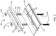
- FIG. 3 illustrates an exploded view of the clamp assembly 144 associated with the base mount assembly 102 in accordance with the preferred embodiment of the present invention.
- the clamp assembly 144 comprises the clamp member 146 that is coupled with the plate member 148.
- the clamp member 146 includes a plurality of apertures 154 (See FIG. 10 ) on an inner surface 156 thereof and a plurality of holes 157 to receive a plurality of screws 178, and the plate member 148 includes a plurality of slots 152.
- the plurality of apertures 154 and the plurality of slots 152 are oriented along a common longitudinal path to receive the at least one securing means 150.
- the clamp assembly 144 is assembled with the base mount assembly 102 when in use.
- the at least one securing means 150 is slid through the horizontal groove 132 and inserted through the plurality of slots 152 on the plate member 148 and the plurality of apertures 154 on the inner surface 156 of the clamp member 146.
- the at least one securing means 150 may comprise a cap screw.
- the at least one securing means 150 is a stainless steel 5/16 "0 ⁇ 2" grade 18/8 machine bolt.
- an engaging nut 160 and a plurality of retainer rings 161 are utilized with the at least one securing means 150 to provide a tight seal.
- the plurality of retainer rings 161 is made of plastic and the engaging nut 160 is a hex nut.
- the engaging nut 160 utilized with the at least one securing means 150 replaces the conventional brake and provides a tight, secure attachment between the clamp assembly 144 and the base mount assembly 102.
- the least one securing means 150 is securely tightened utilizing the lock nut 162.
- the lock nut 162 is a serrated flange hex nut.
- the clamp member 146 replaces the conventional brake and eliminates edge bridge/mid edge conflict.
- This clamp assembly 144 works both on top of the base mount assembly 102 as well as independently.
- Such clamp assembly 144 is adjustable to fit "off-the-shelf" available PV modules.
- the clamp assembly 144 is adjustable to mount most standard size PV modules.
- the clamp assembly 144 can fit all types of framed and frameless PV modules.
- FIG. 4 illustrates a first mounting position of the rail-less roof mounting system 100 interlocking the plurality of PV modules 170, 172, 174 to form a corner-to-corner coupling arrangement in accordance with the preferred embodiment of the present invention.
- the clamp member 146 interconnects the frame member 164 of the PV module 170 to the frame member 166 of the adjacent PV module 172.
- the clamp member 146 is attached to the frame members 164, 166, 168 of the plurality of PV modules 170, 172, 174 by inserting a plurality of screws 178 into the plurality of holes 157 at a middle of a formed PV array.
- the clamp assembly 144 is coupled with the base mount assembly 102, utilizing one of the securing means 150 that is inserted through one of the apertures 154 in the inner surface 156 of the clamp member 146 and one of the slots 152 on the plate member 148.
- FIG. 5 illustrates a second mounting position of the rail-less roof mounting system 100 interlocking the plurality of PV modules 170, 172, 174 to form the corner-to-corner coupling arrangement in accordance with the preferred embodiment of the present invention.
- the clamp member 146 interconnects the frame member 164 of the PV module 170 to the frame member 166 of the adjacent PV module 172.
- the clamp assembly 144 is coupled with the base mount assembly 102 utilizing another securing means 150 that is inserted through another aperture 154 in the inner surface 156 of the clamp member 146 and another slot 152 on the plate member 148.
- the clamp member 146 interlocks corners of the frame members 164, 166, 168 of the plurality of PV modules 170, 172, 174 to form a corner-to-corner coupling arrangement as illustrated in FIGS. 4 and 5 .
- the rail-less roof mounting system 100 is shown in FIGS. 4 and 5 holding three PV modules 170, 172, 174, it is noted that the at least one rail-less roof mounting system 100 can bridge four PV modules at the corners in any row and column configuration.
- the plurality of PV modules 170, 172, 174 are interlocked in a way to provide the corner-to-corner coupling arrangement which enables the connection of PV module corners to adjacent PV module corners by sandwiching above and beneath the frame members 164, 166, 168 of the plurality of PV modules 170, 172, 174.
- the clamp member 146 interlocks top and bottom surfaces of the frame members 164, 166, 168 of the plurality of PV modules 170, 172, 174 as shown in FIGS. 4 and 5 .
- the plurality of PV modules 170, 172, 174 provided is aluminium framed PV modules.
- the present invention will be described for use with a framed PV module, the present invention is not so limited.
- rigid frameless PV modules i.e. PV modules utilizing glass modules, may also be utilized to practice the present invention.
- the corner-to corner coupling arrangement provides connection with other mounting and/or racking components and does not provide attachment or connection with any portion of the roof structure 176 such as waterproofing layers, structural rooftop layers or any/all cosmetic layers.
- FIG. 6 illustrates the rail-less roof mounting system 100 interlocking two PV modules 192, 194 in accordance with an alternate configuration of the present invention.
- the rail-less roof mounting system 100 interlocks top and bottom surfaces of frame members of two adjacent PV modules 192, 194 at an end of a formed PV array.
- FIG. 7 illustrates installation of the rail-less roof mounting system 100 on the roof structure 176 in accordance with the preferred embodiment of the present invention.
- the roof structure 176 serves as a mounting surface for the base mount assembly 102.
- the base member 104 is placed on the roof structure 176 and the at least one tightening means 118 is inserted through the borehole 116, the waterproof means 106 and a roof rafter 180 that is positioned just beneath a roofing material 182 and a roofing sheathing 184.
- the illustrative installation provides a single point of penetration with the elevated seal portion 112 for providing waterproofing. A minimum embedment depth of 2112 inches is preferred.
- the at least one tightening means 118 is a GRK RSS rugged structural screw made of specially hardened steel to provide with high tensile, torque and shear strength.
- the screw has a 5/16 inch nominal diameter underneath the sealing washer 158, a minimum of torque screw to 13 ft-lb and may be made of hardened steel preferably with an all weather coating such as climatek TM coating.
- the roof structure 176 can include pre-stamped and/or pre-drilled pilot holes formed therein through which the at least one tightening means 118 can be inserted.
- the pilot holes have a diameter of about 1/8 of an inch. More profitably, the rail-less roof mounting system 100 is easily and quickly installed with minimal tools, such as a 112 inch open-end box wrench and a 112 inch socket.
- a method for installing a plurality of photovoltaic (PV) modules 170, 172, 174 on a roof structure 176 includes the following steps. Firstly, a rail-less roof mounting system 100 is provided for mounting the plurality of PV modules 170, 172, 174. The base member 104 is placed on the roof structure 176 and the block slider 110 is positioned above the base member 104 by inserting the waterproof means 106 through the borehole 116 on the elevated seal portion 112. The at least one tightening means 118 is inserted through the borehole 116 and the waterproof means 106 to secure the block slider 110 and the base member 104 with the roof structure 176. The sliding seal member 134 is slid over the vertical engaging portion 114 through the sliding groove 136 on the top slider 124.
- PV photovoltaic
- the at least one fastening means 140 is inserted through the vertical groove 120 on the vertical engaging portion 114 and the slot 138 on the top slider 124 to attach the top slider 124 to the block slider 110.
- the at least one fastening means 140 is tightened utilizing the lock nut 162.
- the at least one securing means 150 is slid through the horizontal groove 132 and inserted through the plurality of slots 152 on the plate member 148 and a plurality of apertures 154 on clamp member 146 to attach the clamp member 146 and the plate member 148 with the track 130 of the top slider 124.
- the at least one securing means 150 is tightened utilizing the lock nut 162.
- the clamp member 146 interconnects the frame member 164 of the PV module 170 to the frame member 166 of the adjacent PV module 172 to provide a corner-to-corner coupling arrangement.
- the clamp member 146 is attached with the frame member 164 of the PV module 170 by inserting a plurality of screws 178 into a plurality of holes 157 on the clamp member 146.
- the corner-to-corner coupling arrangement enables the connection of PV module corners to adjacent PV module corners by sandwiching above and beneath the frame members 164, 166, 168 of the plurality of PV modules 170, 172, 174.
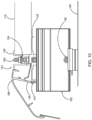
- FIG. 8 illustrates the base mount assembly 102 configured to adjust the mounting height of the rail-less roof mounting system 100 in accordance with the preferred embodiment of the present invention.
- the height of mounting of the rail-less roof mounting system 100 is adjusted by adjusting the position of the top slider 124 along the vertical engaging portion 114 of the block slider 110.
- the top slider 124 can be moved along the vertical engaging portion 114 and can be secured at desired position or height by tightening the at least one fastening means 140 through the vertical groove 120 on the vertical engaging portion 114 and the slot 138 on the sliding seal member 134.
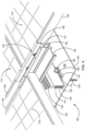
- FIGS. 9 and 10 illustrate perspective and profile views of a PV array skirt 186 providing a snap-fit engagement with the rail-less roof mounting system 100 in accordance with the preferred embodiment of the present invention.
- a PV array skirt 186 is installed on an edge of a PV array.
- the PV array skirt 186 may provide improved aesthetics, safety and structural performance.
- the PV array skirt 186 may partially or fully obscure air gap and mounting hardware located beneath the PV array.
- the PV array skirt 186 may allow for the snap-fit engagement of the PV array skirt 186 to the rail-less roof mounting system 100.
- the rail-less roof mounting system 100 may also allow for the snap-fit engagement with the plurality of PV modules 170, 172, 174.
- the snap-fit engagement between the PV array skirt 186 and the rail-less roof mounting system 100 is achieved by inserting an extrusion 188 of the PV array skirt 186 along a grooved edge 147 of the plate member 148.
- the grooved edge 147 provides a seat for the extrusion 188 of the PV array skirt 186 to provide the snap-fit engagement.
- the snap-fit engagement provides a longer landing ability to the plate member 148 and an ability to easily clean out debris from under the PV array skirt 186.
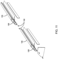
- FIG. 11 illustrates a perspective view of interlocking of two PV array skirts 186 in accordance with the preferred embodiment of the present invention.
- the two PV array skirts 186 are placed end-to-end and ready to be interlocked together with a plurality of skirt clips 190.
- the plurality of skirt clips 190 is adaptable to prevent the PV array skirt 186 from sagging.
- the PV array skirt 186 may be manufactured from bent metal and may snap onto the rail-less roof mounting system 100 via the grooved edge 147 of the plate member 148.
- the rail-less roof mounting system 100 allows for vertical height adjustment therefore allowing for adjustment of height of the PV array skirt 186 above the roof structure 176 thus preventing the debris from entering the underlying air gap.
- a gap provided between the PV array skirt 186 and the frame member 164 may be sized in order to enable adequate room for installing the plurality of wire clips 163 or any other mounting structures.
- the embodiments discussed above allow for portrait orientation, landscape orientation or a combination of both.
- a portrait orientation the PV array having each of the plurality of PV modules 170, 172, 174 oriented, with the longest axis of the plurality of PV modules 170, 172, 174 extend in a forward-rearward direction, which is typically the south-north direction.
- the plurality of PV modules 170, 172, 174 have long edges with length running in cross-slope direction.
- the plurality of PV modules 170, 172, 174 can alternatively be oriented in a landscape orientation, that is, with the longest axis of the plurality of PV modules 170, 172, 174 extending in a lateral or side-to-side direction which is typically the east-west direction.
- the above-disclosed rail-less roof mounting system 100 can be used for gable roofs, hip roofs and flat and low slope gable roofs.
- the plurality of PV modules 170, 172, 174 have short edges with width running in cross-slope direction.
- the rail-less roof mounting system 100 has the ability to cantilever the plurality of PV modules 170, 172, 174 for both portrait and landscape orientation, for example, 13 inch cantilever portrait and 19 inch cantilever landscape.
- the preferred embodiment reduces the number of parts, the size, and the cost of the parts, resulting in a total part count of approximately 151(a 50% reduction) and a total mounting system hardware cost of $0.30/W retail (a 54% reduction). Further, the labor time to install the rail-less roof mounting system 100 is decreased by a minimum of 35%, which results in the reduction of installation times by over 55% as installation efficiencies grow. When the rail-less roof mounting system 100 is installed for bridging the plurality of PV modules 170, 172, 174, it is revealed a decrease of around 47% in non-electrical installation hours. Additional system design and procurement soft-costs are reduced by 67%, when utilizing the system.
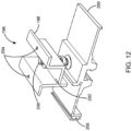
- FIG. 12 illustrates one embodiment of a clamp assembly 196 in accordance with the present invention.
- the clamp assembly 196 is small in size and adaptable to use for end-clamping the plurality of PV modules 170, 172, 174.
- the clamp assembly 196 includes a clamp member 198 and a plate member 200.
- the clamp member 198 includes an aperture (not shown) on an inner surface 202 thereof and a pair of holes (not shown) to receive a pair of screws 204 and the plate member 200 includes a slot (not shown).
- the plate member 200 further includes a grooved edge 206 to accommodate the PV array skirt 186.
- At least one securing means 208 is inserted through the aperture (not shown) of the clamp member 198 and the slot (not shown) of the plate member 200 to engage the clamp member 198 and the plate member 200.
- the presently disclosed system is advantageous because it provides the corner-to-corner coupling arrangement, enabling the bridging of corners of the plurality of PV modules 170, 172, 174.
- the rail-less roof mounting system 100 provides a single grounding lug for assembling the PV array consisting of 300 PV modules or less. Further, the rail-less roof mounting system 100 includes the plurality of wire clips 163, which are designed to work in multiple locations to minimize wire management issues.
- the rail-less roof mounting system 100 allows for more customizability in the PV array shape by allowing the installer to easily work around roof obstructions like vents, skylights, and other roof protrusions This rail-less roof mounting system 100 provides the ability to increase vertical leveling adjustability, for instance, 3 inch to 5 inch.
- the rail-less roof mounting system 100 has the ability to independently remove a single PV module without deconstructing an entire row of the PV array and allow for easy mounting height adjustment after the plurality of PV modules 170, 172, 174 are installed.
- the rail-less roof mounting system 100 can be easily assembled and disassembled and the components can be laid flat for easy storage and shipping. Furthermore, the rail-less roof mounting system 100 would require less manpower to install and rework.
Landscapes
- Engineering & Computer Science (AREA)
- Chemical & Material Sciences (AREA)
- Life Sciences & Earth Sciences (AREA)
- Sustainable Development (AREA)
- Sustainable Energy (AREA)
- Thermal Sciences (AREA)
- Physics & Mathematics (AREA)
- Combustion & Propulsion (AREA)
- Mechanical Engineering (AREA)
- General Engineering & Computer Science (AREA)
- Architecture (AREA)
- Civil Engineering (AREA)
- Structural Engineering (AREA)
- Roof Covering Using Slabs Or Stiff Sheets (AREA)
Applications Claiming Priority (6)
| Application Number | Priority Date | Filing Date | Title |
|---|---|---|---|
| US201361916046P | 2013-12-13 | 2013-12-13 | |
| US14/166,633 US8938932B1 (en) | 2013-12-13 | 2014-01-28 | Rail-less roof mounting system |
| PCT/US2014/070048 WO2015089413A1 (fr) | 2013-12-13 | 2014-12-12 | Système de montage au toit sans rail |
| EP14869459.9A EP3092350B1 (fr) | 2013-12-13 | 2014-12-12 | Système de montage au toit sans rail |
| EP19169688.9A EP3533949B1 (fr) | 2013-12-13 | 2014-12-12 | Système de montage de toit sans rail |
| EP20199467.0A EP3812529B1 (fr) | 2013-12-13 | 2014-12-12 | Système de montage de toit sans rail |
Related Parent Applications (3)
| Application Number | Title | Priority Date | Filing Date |
|---|---|---|---|
| EP20199467.0A Division EP3812529B1 (fr) | 2013-12-13 | 2014-12-12 | Système de montage de toit sans rail |
| EP14869459.9A Division EP3092350B1 (fr) | 2013-12-13 | 2014-12-12 | Système de montage au toit sans rail |
| EP19169688.9A Division EP3533949B1 (fr) | 2013-12-13 | 2014-12-12 | Système de montage de toit sans rail |
Publications (2)
| Publication Number | Publication Date |
|---|---|
| EP4276256A2 true EP4276256A2 (fr) | 2023-11-15 |
| EP4276256A3 EP4276256A3 (fr) | 2024-01-24 |
Family
ID=52350593
Family Applications (4)
| Application Number | Title | Priority Date | Filing Date |
|---|---|---|---|
| EP14869459.9A Active EP3092350B1 (fr) | 2013-12-13 | 2014-12-12 | Système de montage au toit sans rail |
| EP19169688.9A Active EP3533949B1 (fr) | 2013-12-13 | 2014-12-12 | Système de montage de toit sans rail |
| EP23177830.9A Pending EP4276256A3 (fr) | 2013-12-13 | 2014-12-12 | Système de montage de toit sans rail |
| EP20199467.0A Active EP3812529B1 (fr) | 2013-12-13 | 2014-12-12 | Système de montage de toit sans rail |
Family Applications Before (2)
| Application Number | Title | Priority Date | Filing Date |
|---|---|---|---|
| EP14869459.9A Active EP3092350B1 (fr) | 2013-12-13 | 2014-12-12 | Système de montage au toit sans rail |
| EP19169688.9A Active EP3533949B1 (fr) | 2013-12-13 | 2014-12-12 | Système de montage de toit sans rail |
Family Applications After (1)
| Application Number | Title | Priority Date | Filing Date |
|---|---|---|---|
| EP20199467.0A Active EP3812529B1 (fr) | 2013-12-13 | 2014-12-12 | Système de montage de toit sans rail |
Country Status (5)
| Country | Link |
|---|---|
| US (12) | US8938932B1 (fr) |
| EP (4) | EP3092350B1 (fr) |
| AU (3) | AU2014362215B2 (fr) |
| MX (2) | MX2016007728A (fr) |
| WO (1) | WO2015089413A1 (fr) |
Families Citing this family (131)
| Publication number | Priority date | Publication date | Assignee | Title |
|---|---|---|---|---|
| US9447988B2 (en) | 2010-01-25 | 2016-09-20 | Rillito Rive Solar, LLC | Roof mount assembly |
| US20110094559A1 (en) * | 2009-10-23 | 2011-04-28 | Chevron U.S.A. Inc. | Solar canopy support system |
| WO2012082806A2 (fr) * | 2010-12-13 | 2012-06-21 | Zep Solar, Inc. | Appareil à point de fixation discret et système pour panneaux photovoltaïques |
| US9611652B2 (en) | 2011-02-25 | 2017-04-04 | Dustin M. M. Haddock | Mounting device for building surfaces having elongated mounting slot |
| US11689148B2 (en) | 2011-03-01 | 2023-06-27 | Unirac Inc. | Support assembly for photovoltaic modules and mounting system using the same |
| US11190127B2 (en) | 2011-03-01 | 2021-11-30 | Unirac, Inc. | Support assembly for photovoltaic modules and mounting system using the same |
| JP5295436B2 (ja) * | 2011-05-31 | 2013-09-18 | 京セラ株式会社 | 取付部材およびこれを用いた太陽電池アレイ |
| US9698724B2 (en) | 2011-12-13 | 2017-07-04 | Solarcity Corporation | Connecting components for photovoltaic arrays |
| WO2013101597A1 (fr) | 2011-12-29 | 2013-07-04 | Haddock Dustin M M | Dispositif de montage pour panneaux à joints debout |
| US10536108B2 (en) * | 2012-10-12 | 2020-01-14 | Smash Solar, Inc. | Sensing, interlocking solar panel system and installation method |
| US9973142B2 (en) | 2013-03-06 | 2018-05-15 | Vermont Slate and Copper Services, Inc. | Snow fence for a solar panel |
| WO2014151490A1 (fr) * | 2013-03-15 | 2014-09-25 | First Solar, Inc. | Système et procédé pour monter des modules photovoltaïques |
| NL2012098C2 (nl) * | 2013-11-08 | 2015-05-11 | Esdec B V | Draagstructuur voor zonnepanelen en werkwijze voor het vervaardigen van een dergelijke draagstructuur. |
| US9431953B2 (en) | 2014-10-31 | 2016-08-30 | Rillito River Solar, Llc | Height adjustment bracket for roof applications |
| US9985575B2 (en) | 2014-04-07 | 2018-05-29 | Rillito River Solar, Llc | Height adjustment bracket for roof applications |
| US9584062B2 (en) * | 2014-10-16 | 2017-02-28 | Unirac Inc. | Apparatus for mounting photovoltaic modules |
| US9647433B2 (en) * | 2014-11-19 | 2017-05-09 | Ironridge, Inc. | Rail-less solar panel assembly and installation method |
| US11368005B2 (en) * | 2014-11-19 | 2022-06-21 | Ironridge, Inc. | Wire management structure for a rail-less solar panel assembly |
| US9985577B2 (en) * | 2015-01-27 | 2018-05-29 | Ironridge, Inc. | Assembly for locking and grounding solar panel modules to mounting components |
| JP2018511721A (ja) | 2015-03-11 | 2018-04-26 | エコリブリウム ソーラー,インコーポレイテッドEcolibrium Solar,Inc. | 傾斜屋根用太陽光パネル装着システム |
| US10312853B2 (en) * | 2015-03-11 | 2019-06-04 | Ecolibrium Solar, Inc | Sloped roof solar panel mounting system |
| US10756668B2 (en) | 2015-03-11 | 2020-08-25 | Ecouni, Llc | Universal sloped roof solar panel mounting system |
| US9822524B1 (en) * | 2015-06-16 | 2017-11-21 | Russ Edward Meznarich | Brackets for installing building attachments |
| US10461682B2 (en) | 2015-08-03 | 2019-10-29 | Unirac Inc. | Height adjustable solar panel mounting assembly |
| US10340838B2 (en) | 2015-08-03 | 2019-07-02 | Unirac Inc. | Hybrid solar panel mounting assembly with a tilted ledge |
| USD824047S1 (en) | 2016-10-13 | 2018-07-24 | Unirac Inc. | Floating splice extrusion |
| US10594250B2 (en) | 2015-08-03 | 2020-03-17 | Unirac Inc. | Hybrid solar panel mounting assembly |
| US10819271B2 (en) | 2015-08-03 | 2020-10-27 | Unirac Inc. | Height adjustable solar panel mounting assembly with an asymmetric lower bracket |
| USD827157S1 (en) | 2016-10-13 | 2018-08-28 | Unirac Inc. | Base extrusion |
| US9722532B2 (en) * | 2015-08-11 | 2017-08-01 | Solarcity Corporation | Photovoltaic module mounting system |
| US10361652B2 (en) * | 2015-09-14 | 2019-07-23 | Vivint Solar, Inc. | Solar module mounting |
| US10947734B2 (en) * | 2015-09-14 | 2021-03-16 | Pmc Industries, Inc. | Retention apparatus, system and method |
| US10340836B2 (en) * | 2015-11-30 | 2019-07-02 | Solarcity Corporation | Interlock system for mounting and joining photovoltaic modules |
| US10014819B2 (en) | 2016-02-10 | 2018-07-03 | Precision Tech Welding & Machine, Inc. | Solar panel mounting system with adjustment features |
| US9876463B2 (en) | 2016-04-15 | 2018-01-23 | Sunmodo Corporation | Adjustable end clamp for mounting solar panels to roofs |
| USD803040S1 (en) | 2016-04-25 | 2017-11-21 | Unirac Inc. | Helical drive |
| USD800544S1 (en) | 2016-04-25 | 2017-10-24 | Unirac Inc. | Tri-drive nut |
| US9837955B1 (en) * | 2016-06-03 | 2017-12-05 | Unirac Inc. | Assembly for mounting a trim piece to a photovoltaic panel using standardized clamps |
| US10648698B2 (en) * | 2016-07-05 | 2020-05-12 | Solar Frontier K.K. | Securing fixture for photovoltaic cell module |
| US10443896B2 (en) | 2016-07-29 | 2019-10-15 | Rmh Tech Llc | Trapezoidal rib mounting bracket with flexible legs |
| US9954479B1 (en) * | 2016-08-02 | 2018-04-24 | Moti Atia | Mounting apparatus to secure solar panel rails to flat tile roofs |
| US10320325B1 (en) * | 2016-08-02 | 2019-06-11 | Moti Atia | Mounting apparatus to secure solar panel rails to stone-coated metal tile roofs |
| US10277162B1 (en) * | 2016-08-16 | 2019-04-30 | Moti Atia | Mounting apparatus to secure a solar panel rail to stone-coated metal tile roofs |
| US10840850B1 (en) | 2016-08-16 | 2020-11-17 | Moti Atia | Mounting apparatus to secure solar panel rails to asphalt shingle roofs |
| US10998847B2 (en) | 2016-08-23 | 2021-05-04 | Pegasus Solar Inc. | Solar mounting assemblies |
| JP2018040241A (ja) * | 2016-09-01 | 2018-03-15 | 株式会社屋根技術研究所 | 太陽電池モジュールの取付構造及び取付具 |
| US10601362B2 (en) | 2016-09-09 | 2020-03-24 | Pegasus Solar Inc. | Tile replacement solar mounting system |
| US10469023B2 (en) | 2016-09-12 | 2019-11-05 | EcoFasten Solar, LLC | Roof mounting system |
| US9745754B1 (en) * | 2016-09-21 | 2017-08-29 | Yanegijutsukenkyujo Co., Ltd. | Snow guard structure |
| US20180115274A1 (en) * | 2016-10-26 | 2018-04-26 | Pegasus Solar Inc. | Tile replacement solar mounting system |
| WO2018081722A1 (fr) | 2016-10-31 | 2018-05-03 | Haddock Dustin M M | Pince de liaison électrique de panneaux métalliques |
| USD815308S1 (en) | 2016-11-15 | 2018-04-10 | Unirac Inc. | Trimrail extrusion |
| CN106452305B (zh) * | 2016-11-16 | 2018-11-23 | 海宁创源太阳能科技有限公司 | 一种太阳能电池板安装支架及其安装方法 |
| US10781587B2 (en) * | 2016-12-14 | 2020-09-22 | Solsera, Inc. | Structural attachment sealing system |
| US10158321B2 (en) * | 2017-01-03 | 2018-12-18 | Solarcity Corporation | Photovoltaic mounting system |
| US10205419B2 (en) * | 2017-03-30 | 2019-02-12 | Sunrun South Llc | Railless solar module installation systems and devices |
| US10177704B2 (en) * | 2017-04-26 | 2019-01-08 | Sunpower Corporation | Snap-on rail assembly |
| US10211773B2 (en) | 2017-05-24 | 2019-02-19 | Sunmodo Corporation | Height-adjustable solar panel mounting device |
| CN206807354U (zh) * | 2017-06-09 | 2017-12-26 | 北京铂阳顶荣光伏科技有限公司 | 光伏组件的安装支架及安装总成 |
| US10036576B1 (en) | 2017-06-26 | 2018-07-31 | Zia Mounting Solutions, Llc | Multi-level mounting system |
| US11594998B1 (en) * | 2017-06-28 | 2023-02-28 | Sunpower Corporation | Systems and methods for mounting solar panels |
| WO2019028278A1 (fr) * | 2017-08-02 | 2019-02-07 | Global Solar Energy, Inc. | Système de montage de toit destiné à des modules photovoltaïques flexibles |
| US10451315B2 (en) | 2017-08-08 | 2019-10-22 | Unirac Inc. | Universal end clamp for mounting solar panels on structural rails |
| CN109428540A (zh) * | 2017-08-30 | 2019-03-05 | 国基电子(上海)有限公司 | 光伏模组安装套件及其使用方法 |
| US10601360B2 (en) * | 2017-09-08 | 2020-03-24 | Unirac Inc. | Replacement tile mount for mounting solar panels on tile roofs |
| US10605282B1 (en) * | 2017-10-09 | 2020-03-31 | Jonathan Young | Panel mounting device |
| CR20200201A (es) | 2017-10-09 | 2020-12-04 | Rmh Tech | Ensamble de riel con adaptador de montaje lateral invertible para aplicaciones de montaje directo e indirecto |
| US10284136B1 (en) | 2017-10-17 | 2019-05-07 | Unirac Inc. | Narrow flashing for waterproof mounting of solar panels to a roof |
| JP6910648B2 (ja) * | 2017-12-18 | 2021-07-28 | 株式会社屋根技術研究所 | 太陽電池パネルの固定構造及び固定ユニット |
| US12024889B2 (en) * | 2017-12-22 | 2024-07-02 | LN1, Inc. | Anchor platform assembly with angled baseplate |
| US10501939B2 (en) * | 2017-12-22 | 2019-12-10 | Lance Nill | Anchor platform assembly |
| US10469022B2 (en) * | 2018-03-04 | 2019-11-05 | Pmc Industries, Inc. | Photo-voltaic panel retention apparatus, system and method |
| AU2019240320B2 (en) | 2018-03-21 | 2022-10-13 | Rmh Tech Llc | PV module mounting assembly with clamp/standoff arrangement |
| JP6850010B2 (ja) * | 2018-05-30 | 2021-03-31 | 株式会社屋根技術研究所 | パネル部材の固定構造及びパネル部材の固定具 |
| US11594999B2 (en) * | 2018-07-04 | 2023-02-28 | Sabic Global Technologies B.V. | Solar roof forming element, building, and method of forming a roof |
| SE543932C2 (en) | 2018-09-20 | 2021-09-28 | Cc90 Composite Ab | An assembly for mounting solar panels and use of the assembly |
| US11149431B1 (en) | 2018-11-19 | 2021-10-19 | Russ Edward Meznarich | Adjustable brackets for installing building attachments |
| CN113412396A (zh) | 2018-12-14 | 2021-09-17 | Rmh技术有限责任公司 | 用于钉带面板的安装装置 |
| US10951157B1 (en) * | 2019-02-19 | 2021-03-16 | Jonathan W. Young | Panel mounting device with adjustable height mechanism |
| WO2020186115A1 (fr) * | 2019-03-12 | 2020-09-17 | Wencon Development, Inc. Dba Quick Mount Pv | Montures pour toit prêtes pour le rayonnage |
| US11290053B2 (en) | 2019-04-01 | 2022-03-29 | Unirac Inc. | Solar panel mounting apparatus |
| US11522489B2 (en) | 2019-04-01 | 2022-12-06 | Unirac Inc. | Bonding clamp as photovoltaic module mounting equipment |
| USD973015S1 (en) | 2019-04-01 | 2022-12-20 | Unirac Inc. | Bonding clamp |
| US11739785B2 (en) | 2019-04-01 | 2023-08-29 | Unirac Inc. | Trim attachment assembly for mounting solar panel equipment |
| EP3948103A4 (fr) * | 2019-04-04 | 2023-01-04 | Vast Solar Pty Ltd | Ensemble et procédé pour fixer un héliostat à une base |
| US11258400B2 (en) | 2019-04-16 | 2022-02-22 | Unirac Inc. | Height adjustable solar panel mounting system |
| US11967924B2 (en) | 2019-05-01 | 2024-04-23 | Unirac Inc. | Solar panel continuity bonding device |
| US11848636B2 (en) | 2019-06-04 | 2023-12-19 | Pegasus Solar, Inc. | Skip rail system |
| NL2023965B1 (nl) * | 2019-06-21 | 2021-01-25 | Energy Team B V | Zonnepanelensamenstel, set van ten minste één zonnepanelensamenstel en een aantal bevestigingselementen, dak waarop een dergelijke set is aangebracht, en werkwijze voor het op een dak monteren van zonnepanelen |
| EP3997393A1 (fr) * | 2019-06-21 | 2022-05-18 | Energy Team B.V. | Ensemble panneau solaire autoportant, groupe d'au moins un ensemble panneau solaire autoportant et d'une pluralité d'éléments de fixation, toit sur lequel un tel groupe est agencé et procédé de montage de panneaux solaires sur un toit |
| USD945356S1 (en) | 2019-06-27 | 2022-03-08 | Unirac Inc. | Bracket |
| USD958058S1 (en) | 2019-08-02 | 2022-07-19 | Unirac Inc. | Bracket |
| WO2021061866A1 (fr) * | 2019-09-23 | 2021-04-01 | EcoFasten Solar, LLC | Système et appareil de fixation de toit |
| US11428009B2 (en) | 2019-09-30 | 2022-08-30 | Bmic Llc | Self-sealing roof fastener |
| US11377840B2 (en) | 2019-11-26 | 2022-07-05 | Pegasus Solar Inc. | One-piece bonding splice for rails |
| SE544211C2 (en) | 2019-12-27 | 2022-03-01 | Cc90 Composite Ab | A mounting device for mounting solar panels to a structure |
| US11085189B2 (en) | 2020-01-13 | 2021-08-10 | Building Materials Investment Corporation | Impact resistant roofing systems and methods |
| US11824489B2 (en) | 2020-02-03 | 2023-11-21 | Unirac Inc. | Photovoltaic module clamp assembly |
| US11152889B1 (en) * | 2020-03-12 | 2021-10-19 | Sunrun Inc. | Mount assemblies with chemical flashings |
| US11515831B2 (en) * | 2020-03-12 | 2022-11-29 | Sunrun Inc. | Mount assemblies with chemical flashings |
| AU2021239839A1 (en) | 2020-03-16 | 2022-10-06 | Rmh Tech Llc | Mounting device for a metal roof |
| US11041310B1 (en) | 2020-03-17 | 2021-06-22 | Rmh Tech Llc | Mounting device for controlling uplift of a metal roof |
| CA3172393A1 (fr) | 2020-03-23 | 2021-09-30 | Bmic Llc | Systemes de fixation pour la fixation d'un tissu a un toit-terrasse |
| US11962137B2 (en) | 2020-04-21 | 2024-04-16 | Unirac Inc. | Electric junction box mount apparatus |
| CN111600539B (zh) * | 2020-06-28 | 2021-04-27 | 嘉兴技师学院 | 一种具有柔性支架的光伏发电装置 |
| TWI748584B (zh) * | 2020-07-31 | 2021-12-01 | 郭展榕 | 太陽能板屋頂防水結構 |
| US11821574B1 (en) * | 2020-08-01 | 2023-11-21 | Jonathan Young | Panel mount base |
| US11781316B1 (en) * | 2020-08-07 | 2023-10-10 | O'keeffe's, Inc. | Framing device for a fire-rated glass floor |
| US11949369B2 (en) | 2020-08-20 | 2024-04-02 | Unirac Inc. | Clamp apparatuses and components thereof for mounting solar panel modules |
| TWI741817B (zh) * | 2020-09-30 | 2021-10-01 | 林彥志 | 太陽能板防水支架結構 |
| CN112422028B (zh) * | 2020-11-19 | 2021-10-08 | 西南交通大学 | 一种用于高寒地区的风光互补发电装置 |
| USD1004141S1 (en) | 2020-12-01 | 2023-11-07 | Pegasus Solar, Inc. | Rail |
| US12051993B2 (en) | 2020-12-18 | 2024-07-30 | Unirac Inc. | Clamping system for mounting a solar panel |
| US11611310B2 (en) * | 2021-01-22 | 2023-03-21 | Pegasus Solar Inc. | Hinged solar mount |
| US11990862B2 (en) | 2021-02-18 | 2024-05-21 | Pegasus Solar Inc. | Rail accessory mount |
| US20220321054A1 (en) * | 2021-03-30 | 2022-10-06 | John Powers, III | Flat roof solar sensor structures and bolt attachment |
| TWM619347U (zh) * | 2021-04-14 | 2021-11-11 | 綠陽鋼品股份有限公司 | 太陽能板支撐架 |
| USD987412S1 (en) | 2021-04-28 | 2023-05-30 | Unirac Inc. | Panel mount assembly |
| US12068715B2 (en) | 2021-04-28 | 2024-08-20 | Unirac Inc. | Sealable mounting system with a slidable component mount |
| CN113556081B (zh) * | 2021-07-22 | 2022-12-27 | 北京金茂绿建科技有限公司 | 一种房顶光伏发电系统 |
| EP4393057A1 (fr) | 2021-08-24 | 2024-07-03 | IronRidge, Inc. | Système de montage de panneau solaire à base de rail |
| CN114263314B (zh) * | 2022-03-01 | 2022-05-27 | 浙江晴天太阳能科技股份有限公司 | 双玻无边框光伏组件的防水安装方法 |
| CN114775921B (zh) * | 2022-03-23 | 2023-07-28 | 长江精工钢结构(集团)股份有限公司 | 一种建筑光伏屋面可滑移装置 |
| DE102022204681A1 (de) * | 2022-05-13 | 2023-11-16 | Robert Bosch Gesellschaft mit beschränkter Haftung | Verbindungssystem zum Verbinden einer Vorrichtung zum Kühlen und/oder Erwärmen eines Mediums mit einem Fundament |
| US20240154570A1 (en) * | 2022-11-03 | 2024-05-09 | Pegasus Solar, Inc. | Module coupling clamp |
| USD983015S1 (en) | 2022-12-30 | 2023-04-11 | Sunmodo Corporation | Roof mount bracket for mounting solar panels |
| USD983019S1 (en) | 2022-12-30 | 2023-04-11 | Sunmodo Corporation | Roof mount bracket for mounting solar panels |
| USD983016S1 (en) | 2022-12-30 | 2023-04-11 | Sunmodo Corporation | Roof mount bracket for mounting solar panels |
| USD984872S1 (en) | 2022-12-30 | 2023-05-02 | Sunmodo Corporation | Roof mount bracket for mounting solar panels |
| USD983018S1 (en) | 2022-12-30 | 2023-04-11 | Sunmodo Corporation | Roof mount bracket for mounting solar panels |
| US11750143B1 (en) | 2023-01-24 | 2023-09-05 | Sunmodo Corporation | Bracket and devices for mounting solar panels to roofs |
Family Cites Families (258)
| Publication number | Priority date | Publication date | Assignee | Title |
|---|---|---|---|---|
| US562225A (en) * | 1896-06-16 | Karl hutter | ||
| US565505A (en) * | 1896-08-11 | tit-blow | ||
| US519444A (en) * | 1894-05-08 | Hand-pump | ||
| US516017A (en) * | 1894-03-06 | Hot-air heating apparatus | ||
| US564958A (en) * | 1896-07-28 | X xx xx xx x - x - - x -x xx xx | ||
| US510315A (en) * | 1893-12-05 | Julius begtrup | ||
| US511576A (en) * | 1893-12-26 | Rope-buckle | ||
| US1281531A (en) * | 1916-12-22 | 1918-10-15 | Charles W Dietrich | Suspension-clamp. |
| US2731225A (en) * | 1952-03-07 | 1956-01-17 | Julius N Cayo | Antenna mounting |
| US3332186A (en) * | 1963-05-22 | 1967-07-25 | Solvay | System for securing corrugated sheeting |
| US3363864A (en) * | 1966-02-18 | 1968-01-16 | Ove R. Olgreen | Conduit hanger |
| US3630253A (en) * | 1969-10-22 | 1971-12-28 | Lamson & Sessions Co | Interference fastener |
| US4073283A (en) * | 1975-02-27 | 1978-02-14 | Solaron Corporation | Modular construction for solar heat collector |
| US4112922A (en) * | 1976-03-23 | 1978-09-12 | All Sunpower, Inc. | Solar energy collector |
| US4178910A (en) * | 1976-06-25 | 1979-12-18 | Gramer Eben J | Solar collector and system for mounting a plurality of solar collectors on a surface |
| US4176653A (en) * | 1977-02-22 | 1979-12-04 | Pittman Turner J | Inflatable enclosure and energy exchange system |
| FR2401290A1 (fr) * | 1977-08-25 | 1979-03-23 | Saint Gobain | Dispositif de montage de capteurs solaires sur les batiments |
| US4219011A (en) * | 1977-12-01 | 1980-08-26 | Aga Aktiebolag | Modular solar energy collector systems |
| US4146785A (en) * | 1978-02-13 | 1979-03-27 | Sunpower Systems Corporation | Sun-tracking control system for solar collector |
| FR2428215A2 (fr) * | 1978-06-09 | 1980-01-04 | Schwobb Alain | Capteur solaire |
| US4278070A (en) * | 1978-08-21 | 1981-07-14 | Ametek, Inc. | Solar energy collector assembly and sub-assemblies thereof |
| US4347093A (en) * | 1978-09-05 | 1982-08-31 | Pure Power Incorporated | Method of producing an integrated solar roof system |
| IT1159922B (it) * | 1978-10-04 | 1987-03-04 | Pirelli | Tetto solare |
| US4186033A (en) * | 1978-11-01 | 1980-01-29 | Owens-Illinois, Inc. | Structure for conversion of solar radiation to electricity and heat |
| US4345818A (en) * | 1979-12-13 | 1982-08-24 | Blum Alvin S | Solar diodes |
| US4291680A (en) * | 1979-12-26 | 1981-09-29 | Owens-Illinois, Inc. | Double-walled glass solar energy collector |
| US4348846A (en) * | 1980-10-02 | 1982-09-14 | Butler Manufacturing Company | Insulated roof |
| US4429872A (en) * | 1981-08-05 | 1984-02-07 | Capachi Nickolas E | Foul or base lines for athletic activities |
| USD279214S (en) * | 1982-08-30 | 1985-06-11 | Hanson David J | Solar collector |
| IT8305006V0 (it) * | 1983-10-06 | 1983-10-06 | C O M Cooperative Operai Metal | Sistema di coolegamento fra due barre cave coassiali e di sezione sostanzialmente rettangolare |
| US4957601A (en) * | 1984-09-04 | 1990-09-18 | Texas Instruments Incorporated | Method of forming an array of apertures in an aluminum foil |
| US4587952A (en) * | 1985-05-10 | 1986-05-13 | Richardson John L | Passive solar water heater |
| US4680905A (en) * | 1985-08-26 | 1987-07-21 | Ppg Industries, Inc. | Rafter with internal drainage feature and sloped glazing system incorporating same |
| US4677248A (en) * | 1985-09-13 | 1987-06-30 | Lacey Thomas G | Apparatus for mounting solar cells |
| US4691818A (en) * | 1986-01-27 | 1987-09-08 | The Laitram Corp. | Concealed drive coupling for use with modular screw conveyor |
| US4674244A (en) * | 1986-07-17 | 1987-06-23 | Single-Ply Institute Of America, Inc. | Roof construction having insulation structure, membrane and photovoltaic cells |
| US4718185A (en) * | 1986-11-07 | 1988-01-12 | Solar Signage, Inc. | Modular solar generating system |
| US5127762A (en) * | 1989-03-03 | 1992-07-07 | Republic Tool & Mfg. Corp. | Connector assembly |
| US4966631A (en) * | 1989-03-13 | 1990-10-30 | Chronar Corp. | Support for photovoltaic arrays |
| US5143556A (en) * | 1989-03-13 | 1992-09-01 | Matlin Ronald W | Support for photovoltaic arrays |
| US5046791A (en) * | 1989-04-18 | 1991-09-10 | Jerry Kooiman | Extrusion frame and components therefor |
| CA2001136C (fr) * | 1989-10-23 | 1995-02-07 | Takashi Hirai | Toit |
| US5232518A (en) * | 1990-11-30 | 1993-08-03 | United Solar Systems Corporation | Photovoltaic roof system |
| US5203135A (en) * | 1991-03-05 | 1993-04-20 | Hamilton Industries, Inc. | Connection for hollow structural members |
| US5144780A (en) * | 1991-03-25 | 1992-09-08 | Gieling Thomas G | Portable structure |
| US5164020A (en) * | 1991-05-24 | 1992-11-17 | Solarex Corporation | Solar panel |
| JPH0571520A (ja) * | 1991-05-29 | 1993-03-23 | Toopura:Kk | ドリリングねじ |
| US5164019A (en) * | 1991-07-31 | 1992-11-17 | Sunpower Corporation | Monolithic series-connected solar cells having improved cell isolation and method of making same |
| DE4205140C1 (fr) * | 1992-02-20 | 1993-05-27 | Braas Gmbh, 6370 Oberursel, De | |
| US5316592A (en) * | 1992-08-31 | 1994-05-31 | Dinwoodie Thomas L | Solar cell roofing assembly |
| AU669399B2 (en) * | 1992-11-19 | 1996-06-06 | Hirai Engineering Corporation | Roof system utilizing a solar cell |
| US5524401A (en) * | 1993-01-12 | 1996-06-11 | Misawa Homes Co., Ltd. | Roof with solar battery |
| US5596981A (en) * | 1993-07-19 | 1997-01-28 | Soucy; Paul B. | Solar device and method for assembly |
| JPH07202242A (ja) * | 1993-11-26 | 1995-08-04 | Sanyo Electric Co Ltd | 太陽電池モジュール及び太陽電池装置 |
| US5505788A (en) * | 1994-06-29 | 1996-04-09 | Dinwoodie; Thomas L. | Thermally regulated photovoltaic roofing assembly |
| WO1996007803A1 (fr) * | 1994-09-08 | 1996-03-14 | Non-Compact, Inc. | Systeme de montage de panneaux de construction |
| US5628580A (en) * | 1995-04-19 | 1997-05-13 | B-Line Systems, Inc. | Splice system |
| USD374169S (en) * | 1995-06-09 | 1996-10-01 | Krueger International, Inc. | Connector for a pair of furniture post sections |
| US5603187A (en) * | 1995-07-05 | 1997-02-18 | Merrin; William R. | Watertight system for mounting equipment on roof |
| US5746029A (en) * | 1995-12-07 | 1998-05-05 | Ullman; Stanley A. | Tile roof structure for supporting a heavy load without damage to the tile |
| US5746839A (en) * | 1996-04-08 | 1998-05-05 | Powerlight Corporation | Lightweight, self-ballasting photovoltaic roofing assembly |
| FR2747707B1 (fr) * | 1996-04-18 | 1999-04-09 | Seyller Francois Philippe | Dispositif de toiture permettant la modulation et la repartition de l'ensoleillement |
| USD387655S (en) * | 1996-04-18 | 1997-12-16 | Krueger International | Connector for a pair of furniture post sections |
| US6182403B1 (en) * | 1996-08-30 | 2001-02-06 | Canon Kabushiki Kaisha | Combination solar battery and roof unit and mounting method thereof |
| JP3610178B2 (ja) * | 1997-02-05 | 2005-01-12 | キヤノン株式会社 | 屋根及びその施工方法 |
| US5976930A (en) * | 1997-04-25 | 1999-11-02 | Micron Technology, Inc. | Method for forming gate segments for an integrated circuit |
| NL1006187C2 (nl) * | 1997-05-30 | 1999-01-07 | Mammoet Decalift Int Bv | Hijsinrichting voor grote lasten. |
| US6061978A (en) * | 1997-06-25 | 2000-05-16 | Powerlight Corporation | Vented cavity radiant barrier assembly and method |
| US6148570A (en) * | 1998-02-05 | 2000-11-21 | Powerlight Corporation | Photovoltaic building assembly with continuous insulation layer |
| JPH11150287A (ja) * | 1997-09-10 | 1999-06-02 | Canon Inc | 太陽電池モジュール、太陽電池付き外囲体、太陽電池付き外囲体の設置方法、及び太陽光発電システム |
| US6105317A (en) * | 1997-09-24 | 2000-08-22 | Matsushita Electric Works, Ltd. | Mounting system for installing an array of solar battery modules of a panel-like configuration on a roof |
| JP3792867B2 (ja) * | 1997-11-06 | 2006-07-05 | キヤノン株式会社 | 太陽電池モジュール、太陽電池アレイ及び太陽光発電装置の施工方法 |
| JP3586083B2 (ja) * | 1997-11-13 | 2004-11-10 | キヤノン株式会社 | 太陽電池モジュールの配置方法及び太陽電池モジュールアレイ |
| US5960790A (en) * | 1997-12-22 | 1999-10-05 | Rich; Albert Clark | Modular solar energy collection system |
| JP3937654B2 (ja) * | 1998-06-30 | 2007-06-27 | キヤノン株式会社 | 太陽電池モジュール、その設置方法、ならびにそれを用いた太陽光発電装置および屋根 |
| US6111189A (en) * | 1998-07-28 | 2000-08-29 | Bp Solarex | Photovoltaic module framing system with integral electrical raceways |
| US6035595A (en) * | 1998-10-29 | 2000-03-14 | Anderson; Kirk D. | Self-sealing fastener |
| JP2975998B1 (ja) * | 1998-11-10 | 1999-11-10 | 株式会社上甲製作所 | 太陽電池屋根構造 |
| US6586668B2 (en) * | 1999-02-05 | 2003-07-01 | Powerlight Corporation | Electric vehicle with photovoltaic roof assembly |
| US6201180B1 (en) * | 1999-04-16 | 2001-03-13 | Omnion Power Engineering Corp. | Integrated photovoltaic system |
| US6295818B1 (en) * | 1999-06-29 | 2001-10-02 | Powerlight Corporation | PV-thermal solar power assembly |
| US6675580B2 (en) * | 1999-06-29 | 2004-01-13 | Powerlight Corporation | PV/thermal solar power assembly |
| DE19934073B4 (de) * | 1999-07-19 | 2005-08-25 | Regen Energiesysteme Gmbh | Vorrichtung zur Befestigung von Solarmodulen |
| US6568873B1 (en) * | 1999-07-20 | 2003-05-27 | Wallace H. Peterson | In-line connector for window spacer frame tubing |
| JP3767287B2 (ja) * | 1999-11-11 | 2006-04-19 | 三菱電機株式会社 | 太陽電池パネルの固定装置 |
| DE19958622C1 (de) * | 1999-12-06 | 2001-08-23 | Dorma Gmbh & Co Kg | Klemmbeschlag für eine Glasplatte |
| US6761008B2 (en) * | 1999-12-14 | 2004-07-13 | Mannington Mills, Inc. | Connecting system for surface coverings |
| US7169460B1 (en) * | 1999-12-14 | 2007-01-30 | Mannington Mills, Inc. | Thermoplastic planks and methods for making the same |
| US6387726B1 (en) * | 1999-12-30 | 2002-05-14 | Sunpower Corporation | Method of fabricating a silicon solar cell |
| US6423568B1 (en) * | 1999-12-30 | 2002-07-23 | Sunpower Corporation | Method of fabricating a silicon solar cell |
| US6337283B1 (en) * | 1999-12-30 | 2002-01-08 | Sunpower Corporation | Method of fabricating a silicon solar cell |
| US6274402B1 (en) * | 1999-12-30 | 2001-08-14 | Sunpower Corporation | Method of fabricating a silicon solar cell |
| US6360491B1 (en) * | 2000-01-14 | 2002-03-26 | Stanley A. Ullman | Roof support system for a solar panel |
| US6453623B1 (en) * | 2000-01-24 | 2002-09-24 | Roofers - Annex Inc. | Roof snow barrier |
| JP3483824B2 (ja) * | 2000-03-07 | 2004-01-06 | 聖州企業股▲ふん▼有限公司 | 自動車のルーフトップ取付け型屋外遮光装置 |
| US6313395B1 (en) * | 2000-04-24 | 2001-11-06 | Sunpower Corporation | Interconnect structure for solar cells and method of making same |
| US6414237B1 (en) * | 2000-07-14 | 2002-07-02 | Astropower, Inc. | Solar collectors, articles for mounting solar modules, and methods of mounting solar modules |
| JP2002141541A (ja) * | 2000-10-31 | 2002-05-17 | Canon Inc | 太陽光発電装置および建造物 |
| WO2002041407A1 (fr) * | 2000-11-16 | 2002-05-23 | Kaneka Corporation | Module de batterie solaire, systeme de production d'energie photovoltaique, bloc de support supportant ce module de batterie solaire, et procede d'installation d'un systeme de production d'energie photovoltaique |
| US6450475B1 (en) * | 2000-12-29 | 2002-09-17 | Mustek Systems Inc. | Platform adjustment device for scanner |
| US6439344B1 (en) * | 2001-01-26 | 2002-08-27 | Mc Enterprises International, Inc. | Concrete mounted safety stanchion and apparatus and methods for mounting to concrete |
| WO2002095153A1 (fr) * | 2001-05-24 | 2002-11-28 | Johannes Petrus Du Preez | Raccords de poutres de charpente |
| US6676326B2 (en) * | 2001-06-25 | 2004-01-13 | Wen-Chang Wu | Square lamp post insertional conjoinment structure |
| US6570084B2 (en) * | 2001-07-10 | 2003-05-27 | Powerlight Corporation | Pressure equalizing photovoltaic assembly and method |
| US6534703B2 (en) * | 2001-07-10 | 2003-03-18 | Powerlight Corporation | Multi-position photovoltaic assembly |
| US6495750B1 (en) * | 2001-07-10 | 2002-12-17 | Powerlight Corporation | Stabilized PV system |
| US6501013B1 (en) * | 2001-07-10 | 2002-12-31 | Powerlight Corporation | Photovoltaic assembly array with covered bases |
| US7434362B2 (en) * | 2001-07-20 | 2008-10-14 | Unirac, Inc. | System for removably and adjustably mounting a device on a surface |
| US6634077B2 (en) * | 2001-07-20 | 2003-10-21 | Affordable Building Systems | Combined connecting and alignment method for composite fiber building panels |
| US6722357B2 (en) * | 2001-08-15 | 2004-04-20 | Powerlight Corporation | Fixed angle solar collector arrangement |
| US20030066996A1 (en) * | 2001-09-14 | 2003-04-10 | Crane Plastics Company Llc | Fence assembly with connectors |
| US6672018B2 (en) * | 2001-10-12 | 2004-01-06 | Jefferson Shingleton | Solar module mounting method and clip |
| WO2003044299A2 (fr) * | 2001-11-16 | 2003-05-30 | First Solar, Llc | Generateur photovoltaique |
| JP3920083B2 (ja) * | 2001-11-26 | 2007-05-30 | 株式会社Msk | 雪止め構造 |
| US6688047B1 (en) * | 2002-01-24 | 2004-02-10 | Berger Financial Corp. | Snow retention apparatus and method of installation |
| KR100831793B1 (ko) * | 2002-02-04 | 2008-05-28 | 엘지전자 주식회사 | 쿨러 |
| US7043884B2 (en) * | 2002-02-14 | 2006-05-16 | Eurogramco,S. L. | Cladding system |
| US20030154667A1 (en) * | 2002-02-20 | 2003-08-21 | Dinwoodie Thomas L. | Shingle system |
| US7435897B2 (en) * | 2002-04-11 | 2008-10-14 | Schott Solar, Inc. | Apparatus and method for mounting photovoltaic power generating systems on buildings |
| US20040216399A1 (en) * | 2003-01-30 | 2004-11-04 | Kyocera Corporation | Fixing apparatus |
| US7600349B2 (en) * | 2003-02-26 | 2009-10-13 | Unirac, Inc. | Low profile mounting system |
| US7339110B1 (en) * | 2003-04-10 | 2008-03-04 | Sunpower Corporation | Solar cell and method of manufacture |
| US6959517B2 (en) * | 2003-05-09 | 2005-11-01 | First Solar, Llc | Photovoltaic panel mounting bracket |
| US6986494B2 (en) * | 2003-05-15 | 2006-01-17 | Dyneter Industries Ltd. | Self-aligning mounting bracket and system for mounting a planar structure to a fixed structure |
| US7172184B2 (en) * | 2003-08-06 | 2007-02-06 | Sunpower Corporation | Substrate carrier for electroplating solar cells |
| US7592537B1 (en) * | 2004-02-05 | 2009-09-22 | John Raymond West | Method and apparatus for mounting photovoltaic modules |
| US7856769B2 (en) * | 2004-02-13 | 2010-12-28 | Pvt Solar, Inc. | Rack assembly for mounting solar modules |
| US7297866B2 (en) * | 2004-03-15 | 2007-11-20 | Sunpower Corporation | Ventilated photovoltaic module frame |
| US7406800B2 (en) * | 2004-05-18 | 2008-08-05 | Andalay Solar, Inc. | Mounting system for a solar panel |
| ATE364236T1 (de) * | 2004-07-12 | 2007-06-15 | Haeberlein Lehr Ulla | Modulares stecksystem zur sicheren lagerung von horizontal gestapelten photovoltaik-modulen beim transport |
| JPWO2006016412A1 (ja) * | 2004-08-12 | 2008-05-01 | 三菱電機株式会社 | 太陽電池ユニットの取付装置 |
| US8141306B2 (en) * | 2004-10-22 | 2012-03-27 | Kyocera Corporation | Solar battery module device and method of installing the same |
| US20060156648A1 (en) * | 2005-01-04 | 2006-07-20 | Thompson Daniel S | Apparatus for mounting a solar panel or other article to a roof or other structure |
| EP1721107B1 (fr) * | 2005-01-10 | 2007-09-05 | Conergy AG | Systeme de montage a coulisseau filete |
| USD519444S1 (en) * | 2005-04-15 | 2006-04-25 | Powerlight Coporation | Side and end deflector for solar panel |
| US7745722B2 (en) * | 2005-10-06 | 2010-06-29 | Bp Corporation North America Inc. | System for mounting a solar module on a roof or the like and method of installing |
| EP2008343B1 (fr) * | 2006-03-09 | 2017-08-09 | SunPower Corporation, Systems | Pince de montage de module photovoltaique avec mise à la terre integrée |
| US8092129B2 (en) * | 2006-04-21 | 2012-01-10 | Hubbell Incorporated | Bonding washer |
| GB0610031D0 (en) * | 2006-05-19 | 2006-06-28 | Solar Century Holdings Ltd | Solar panel roof mounting system |
| US7506477B2 (en) * | 2006-06-30 | 2009-03-24 | Lumeta, Inc. | Profile roof tile with integrated photovoltaic module |
| US8806813B2 (en) * | 2006-08-31 | 2014-08-19 | Pvt Solar, Inc. | Technique for electrically bonding solar modules and mounting assemblies |
| US7762027B1 (en) * | 2006-09-28 | 2010-07-27 | Wentworth Stuart H | System for attaching an article to a roof and method of use |
| US7857269B2 (en) * | 2006-11-29 | 2010-12-28 | Pvt Solar, Inc. | Mounting assembly for arrays and other surface-mounted equipment |
| DE102007027997B4 (de) * | 2007-06-14 | 2012-12-06 | Fath Gmbh Kunststoff- Und Stahltechnik | Befestigungseinrichtung für an einem Gestellaufbau anzuordnende flächige rahmenlose Bauteile, insbesondere Solarmodule |
| US7861485B1 (en) * | 2007-06-26 | 2011-01-04 | Wentworth Stuart H | Method for installing a stanchion on a tile roof and system therefor |
| US8505248B1 (en) * | 2007-09-21 | 2013-08-13 | Andalay Solar, Inc. | Minimal ballasted surface mounting system and method |
| US8813460B2 (en) * | 2007-09-21 | 2014-08-26 | Andalay Solar, Inc. | Mounting system for solar panels |
| DE102007056600B4 (de) * | 2007-11-21 | 2011-05-05 | Solon Se | Photovoltaikanlage mit einer Matrix aus rahmenlosen Solarmodulen |
| DK2063199T3 (da) * | 2007-11-23 | 2012-09-03 | Belectric Trading Gmbh | Arrangement bestående af et fastgørelsesunderlag med solcellemoduler |
| FR2926098B1 (fr) * | 2008-01-04 | 2010-02-19 | Photowatt Internat | Element modulaire avec module photovoltaique. |
| KR101467600B1 (ko) | 2008-02-11 | 2014-12-05 | 존 알. 웨스트 | 광전지 어레이를 형성 및 장착하기 위한 방법 및 장치 |
| AU2009221660A1 (en) * | 2008-03-07 | 2009-09-11 | Unirac, Inc. | Friction lock bolt |
| EP2304337A1 (fr) * | 2008-05-08 | 2011-04-06 | Solar Power, Inc. | Système de supports pour panneaux solaires montés sur toiture en terrasse |
| WO2009143162A1 (fr) * | 2008-05-19 | 2009-11-26 | Powermount Systems Inc. | Système de montage photovoltaïque avec connecteurs de verrouillage, hauteur de rail ajustable et verrou charnière |
| US8251326B2 (en) * | 2008-05-22 | 2012-08-28 | Mainstream Energy Corporation | Camming clamp for roof seam |
| DE102008027857A1 (de) * | 2008-06-11 | 2009-03-05 | Leichtmetallbau Schletter Gmbh | Montagesystem für PV-Module |
| CN101387151B (zh) * | 2008-09-18 | 2011-05-11 | 吴文强 | 平板紧固系统 |
| DE102008051249A1 (de) * | 2008-10-10 | 2010-04-29 | Sunfilm Ag | Photovoltaikanlage, Photovoltaikmodul und Verfahren zur Bestückung einer Photovoltaikanlage |
| US10277159B2 (en) * | 2008-11-17 | 2019-04-30 | Kbfx Llc | Finished multi-sensor units |
| DE202009001098U1 (de) * | 2009-01-27 | 2009-04-30 | Mounting Systems Gmbh | Solarmodulbefestigung |
| US7658356B1 (en) * | 2009-01-29 | 2010-02-09 | Unistrut International Corporation | Mounting bracket for solar panel applications |
| US8661765B2 (en) * | 2009-02-05 | 2014-03-04 | D Three Enterprises, Llc | Interlocking shape for use in construction members |
| US8448405B2 (en) * | 2009-02-05 | 2013-05-28 | D Three Enterprises, Llc | Roof mount sealing assembly |
| US8153700B2 (en) * | 2010-03-19 | 2012-04-10 | Vermont Slate & Copper Services, Inc. | Roofing system and method |
| US8826618B2 (en) * | 2011-03-15 | 2014-09-09 | Vermont Slate & Copper Services, Inc. | Roof mount assembly |
| US8209914B2 (en) * | 2010-01-25 | 2012-07-03 | Vermont Slate & Copper Services, Inc. | Roofing grommet forming a seal between a roof-mounted structure and a roof |
| US9447988B2 (en) * | 2010-01-25 | 2016-09-20 | Rillito Rive Solar, LLC | Roof mount assembly |
| US9134044B2 (en) * | 2010-01-25 | 2015-09-15 | Vermont Slate & Copper Services, Inc. | Roof mount assembly |
| WO2010104372A1 (fr) * | 2009-03-09 | 2010-09-16 | J. Van Walraven Holding B.V. | Système de support sur toit |
| DE202009003633U1 (de) * | 2009-03-16 | 2009-06-04 | Schletter Gmbh | Vorrichtung zur Befestigung von Balken und anderen Bauteilen |
| US8256169B2 (en) * | 2009-03-20 | 2012-09-04 | Northern States Metals Company | Support system for solar panels |
| US8240109B2 (en) * | 2009-03-20 | 2012-08-14 | Northern States Metals Company | Support system for solar panels |
| US8316590B2 (en) * | 2009-03-20 | 2012-11-27 | Northern States Metals Company | Support system for solar panels |
| US8418418B2 (en) * | 2009-04-29 | 2013-04-16 | 3Form, Inc. | Architectural panels with organic photovoltaic interlayers and methods of forming the same |
| US20100275975A1 (en) * | 2009-04-30 | 2010-11-04 | Jonathan Monschke | Solar panel systems |
| US8413944B2 (en) * | 2009-05-01 | 2013-04-09 | Applied Energy Technologies | Mounting systems for solar panels |
| BE1018771A3 (nl) * | 2009-06-05 | 2011-08-02 | Segers Bvba | Bevestigingssysteem voor zonnepanelen op platte daken, met dakdoorvoer voorzien van thermische onderbreking. |
| FR2947099B1 (fr) * | 2009-06-17 | 2013-11-15 | Cynegy Holdings France | Tuile photovoltaique pour toiture |
| WO2011022125A2 (fr) | 2009-07-02 | 2011-02-24 | Zep Solar, Inc. | Appareil, système et procédé de nivellement densembles de panneaux photovoltaïques |
| US8511006B2 (en) * | 2009-07-02 | 2013-08-20 | Owens Corning Intellectual Capital, Llc | Building-integrated solar-panel roof element systems |
| US8991114B2 (en) * | 2009-07-02 | 2015-03-31 | Zep Solar, Llc | Pivot-fit connection apparatus, system, and method for photovoltaic modules |
| US8657545B2 (en) * | 2009-11-25 | 2014-02-25 | Thomas & Betts International, Inc. | Strut clamp |
| US8695290B1 (en) * | 2009-12-07 | 2014-04-15 | Ironridge, Inc. | Systems and methods for splicing solar panel racks |
| US8025508B2 (en) * | 2009-12-23 | 2011-09-27 | Hubbell Incorporated | Solar panel grounding connector |
| JP5566706B2 (ja) * | 2010-01-15 | 2014-08-06 | 菊川工業株式会社 | 外装材設置構造 |
| US10472828B2 (en) * | 2010-01-25 | 2019-11-12 | EcoFasten Solar, LLC | Roof mounting system |
| US8122648B1 (en) * | 2010-02-02 | 2012-02-28 | Jun Liu | Roof mounting system |
| JP5113859B2 (ja) * | 2010-02-02 | 2013-01-09 | 株式会社屋根技術研究所 | 固定部材 |
| US20110197954A1 (en) * | 2010-02-15 | 2011-08-18 | Xunlight Corporation | Photovoltaic apparatus and photovoltaic array attached to a support structure |
| FR2956423B1 (fr) * | 2010-02-16 | 2014-01-10 | Soprema | Dispositif de fixation de plaques ou de panneaux sur une couverture et couverture composite resultante |
| US20110197521A1 (en) * | 2010-02-16 | 2011-08-18 | Michael Robert Courtney | System of modular construction and assembled structure |
| US10054336B2 (en) * | 2010-03-03 | 2018-08-21 | Robert M. M. Haddock | Photovoltaic module mounting assembly |
| US8495839B2 (en) * | 2010-04-01 | 2013-07-30 | Yanegijutsukenkyujo Co., Ltd. | Installation structure of solar cell module |
| US8181402B2 (en) * | 2010-04-01 | 2012-05-22 | Yanegijutsukenkyujo Co., Ltd. | Building-integrated photovoltaic power unit |
| FR2961300B1 (fr) * | 2010-06-14 | 2014-05-09 | Inst Rech Fondamentale En Technologies Solaires Irfts | Structure de solidarisation de panneaux photovoltaiques sur un bati |
| US10700633B2 (en) * | 2010-07-16 | 2020-06-30 | Strategic Solar Energy, Llc | Protection of electrical components in solar energy shade structure |
| US8661747B2 (en) * | 2010-07-23 | 2014-03-04 | Kristian Eide | Solar panel racking system |
| WO2012033534A2 (fr) * | 2010-09-09 | 2012-03-15 | Sunconnect Corporation | Structure de support de panneau solaire |
| US8984818B2 (en) * | 2010-10-06 | 2015-03-24 | Sunrun South Llc | Snap-in mounting systems for laminate solar panels |
| US8479455B2 (en) * | 2010-10-14 | 2013-07-09 | D Three Enterprises | Flashing assembly |
| US8727291B2 (en) * | 2010-10-19 | 2014-05-20 | Sundance Renewable Solutions, Inc. | Apparatus for securing panels to substrates |
| JP5909499B2 (ja) * | 2010-12-09 | 2016-04-26 | ソーラーシティ コーポレーション | 光起電力アレイ用のスカート |
| CA2820935A1 (fr) * | 2010-12-09 | 2012-06-14 | Zep Solar, Inc. | Appareil et systeme de liaison pivot pour panneaux photovoltaiques |
| WO2012082806A2 (fr) * | 2010-12-13 | 2012-06-21 | Zep Solar, Inc. | Appareil à point de fixation discret et système pour panneaux photovoltaïques |
| US8631614B2 (en) * | 2010-12-31 | 2014-01-21 | Robert D. Livsey | Roofing product with integrated photovoltaic elements and flashing system |
| DE202011001761U1 (de) * | 2011-01-20 | 2011-04-21 | Vm Edelstahltechnik Gmbh | Klemmvorrichtung |
| US8839573B2 (en) * | 2011-02-11 | 2014-09-23 | Northern States Metals Company | Spring clip |
| KR20120096175A (ko) * | 2011-02-22 | 2012-08-30 | 엘지전자 주식회사 | 태양전지 모듈용 프레임 시스템 |
| US8572909B2 (en) * | 2011-03-24 | 2013-11-05 | Solar Mounting Solutions, LLC | Flat roof solar racking system |
| TWI422789B (zh) * | 2011-04-28 | 2014-01-11 | Au Optronics Corp | 太陽能裝置 |
| JP5295436B2 (ja) * | 2011-05-31 | 2013-09-18 | 京セラ株式会社 | 取付部材およびこれを用いた太陽電池アレイ |
| DE102011052129B4 (de) * | 2011-06-03 | 2022-11-03 | K2 Systems Gmbh | Befestigungssystem zur Befestigung von Solarmodulen |
| US8365479B2 (en) * | 2011-06-17 | 2013-02-05 | Phat Energy Corporation | Solar power structure |
| US8683751B2 (en) * | 2011-07-08 | 2014-04-01 | Vermont Slate & Copper Services, Inc. | Roof mount having built-in failure |
| US9160273B2 (en) * | 2011-07-08 | 2015-10-13 | Unirac, Inc. | Universal end clamp |
| US8782972B2 (en) * | 2011-07-14 | 2014-07-22 | Owens Corning Intellectual Capital, Llc | Solar roofing system |
| US9595910B2 (en) * | 2011-07-18 | 2017-03-14 | James L. Grimsley | Solar assembly and method of forming same |
| US8590223B2 (en) * | 2011-08-29 | 2013-11-26 | A. Raymond Et Cie | Solar panel assembly attachment apparatus |
| DE102011111449B4 (de) * | 2011-08-30 | 2014-07-17 | Carl Freudenberg Kg | Klemmmverbindung zur Befestigung von plattenförmigen Bauelementen insbesondere von Solarmodulen |
| US20130048816A1 (en) * | 2011-08-31 | 2013-02-28 | Stuart H. Wentworth | Rackless Height Adjustable Mount For Attaching An Article To A Roof |
| WO2013043816A1 (fr) * | 2011-09-23 | 2013-03-28 | Vermont Slate & Copper Services, Inc. | Ensemble de montage de toit et son procédé de montage |
| US8813532B2 (en) * | 2011-09-29 | 2014-08-26 | James L. Prentice | Adjustable solar panel cap and method of manufacturing same |
| US10302333B2 (en) * | 2011-09-30 | 2019-05-28 | Sunrun South Llc | Wind tunnel optimized solar panel system |
| US8745935B2 (en) * | 2011-10-14 | 2014-06-10 | A. Raymond Et Cie | Photovoltaic panel fastening system |
| ES2662378T3 (es) * | 2011-10-26 | 2018-04-06 | Adensis Gmbh | Sistema de sujeción para el montaje de un módulo fotovoltaico |
| US8756881B2 (en) * | 2011-11-09 | 2014-06-24 | Zep Solar, Llc | Solar panel attachment system |
| US9003726B2 (en) * | 2011-11-14 | 2015-04-14 | The RAQ, LLC | System and method for establishing a self-aligning mounting system for mounting photovoltaic modules |
| US20130291472A1 (en) * | 2011-11-14 | 2013-11-07 | Sader Power Enterprises, LLC | Removable water cap for photovoltaic module mounting system |
| FR2983502B1 (fr) * | 2011-12-02 | 2015-02-06 | Imperbel N V Sa | Dispositif de fixation de panneaux photovoltaiques |
| TWI425646B (zh) * | 2012-01-06 | 2014-02-01 | Au Optronics Corp | 光伏陣列系統、其光伏裝置及其光伏裝置的側框件 |
| US8613169B2 (en) * | 2012-01-06 | 2013-12-24 | Miasole | Electrical routing structures for building integrable photovoltaic arrays |
| US8713881B2 (en) * | 2012-01-27 | 2014-05-06 | A. Raymond Et Cie | Solar panel securing system |
| US10451314B2 (en) * | 2012-02-08 | 2019-10-22 | Preformed Line Products | Solar panel clamp |
| US8505864B1 (en) * | 2012-02-29 | 2013-08-13 | Imp Inc. | PV kit for roof assembly |
| CN103375931A (zh) * | 2012-04-20 | 2013-10-30 | 富泰华工业(深圳)有限公司 | 太阳能板转动装置 |
| US8898969B2 (en) * | 2012-05-04 | 2014-12-02 | Bisem, Inc. | Net-zero energy curtain wall |
| US8752338B2 (en) * | 2012-05-04 | 2014-06-17 | D Three Enterprises, Llc | Adjustable roof mounting system |
| DE102012009486A1 (de) * | 2012-05-09 | 2013-11-14 | K2 Systems Gmbh | Solarmodulhalter |
| WO2013173196A1 (fr) * | 2012-05-13 | 2013-11-21 | Leonid Goldstein | Dispositif solaire photovoltaïque aéroporté |
| US9087947B2 (en) * | 2012-06-15 | 2015-07-21 | Kanzo, Inc. | Clamp for mounting solar modules |
| US9976297B2 (en) * | 2012-06-25 | 2018-05-22 | Sunpower Corporation | Anchor for solar module |
| US8683761B2 (en) * | 2012-06-25 | 2014-04-01 | Sunpower Corporation | Mounting system for solar module array |
| US9010041B2 (en) * | 2012-06-25 | 2015-04-21 | Sunpower Corporation | Leveler for solar module array |
| US8925263B2 (en) * | 2012-08-13 | 2015-01-06 | Dustin M. M. Haddock | Photovoltaic module mounting assembly |
| US8549793B1 (en) * | 2012-08-31 | 2013-10-08 | Ejot Baubefestigung Gmbh | Flashing system |
| CN103697032B (zh) * | 2012-09-28 | 2016-01-06 | 富昱能源科技(昆山)有限公司 | 锁固装置 |
| US10135386B2 (en) * | 2012-10-12 | 2018-11-20 | Smash Solar, Inc. | Sensing, interlocking solar module system and installation method |
| US8740163B1 (en) * | 2012-10-31 | 2014-06-03 | Innovative Medical Products Inc. | Insulated connector for attaching a solar unit to a roof |
| US8938921B2 (en) * | 2012-11-13 | 2015-01-27 | Paul H. Hartman | Integrated solar, daylight and night cooling system |
| US8935893B2 (en) * | 2013-05-31 | 2015-01-20 | Sunmodo Corporation | Direct rooftop mounting apparatus for solar panels |
| US10256765B2 (en) * | 2013-06-13 | 2019-04-09 | Building Materials Investment Corporation | Roof integrated photovoltaic system |
| US9209609B2 (en) * | 2013-06-26 | 2015-12-08 | Cablofil Inc. | Cable tray system with splice plate |
| US10432132B2 (en) * | 2013-07-01 | 2019-10-01 | RBI Solar, Inc. | Solar mounting system having automatic grounding and associated methods |
| US9080792B2 (en) * | 2013-07-31 | 2015-07-14 | Ironridge, Inc. | Method and apparatus for mounting solar panels |
| US9097443B2 (en) * | 2013-10-15 | 2015-08-04 | Sunmodo Corporation | Solar panel rooftop mounting and grounding device |
| US8776456B1 (en) * | 2013-10-21 | 2014-07-15 | Sunmodo Corporation | Solar panel tile roof mounting device |
| US9825581B2 (en) * | 2013-11-14 | 2017-11-21 | Ecolibrium Solar, Inc. | Modular sloped roof solar mounting system |
| US9394693B2 (en) * | 2013-11-22 | 2016-07-19 | Gregory S. Daniels | Roof vent for supporting a solar panel |
-
2014
- 2014-01-28 US US14/166,633 patent/US8938932B1/en active Active
- 2014-12-12 EP EP14869459.9A patent/EP3092350B1/fr active Active
- 2014-12-12 MX MX2016007728A patent/MX2016007728A/es active IP Right Grant
- 2014-12-12 AU AU2014362215A patent/AU2014362215B2/en active Active
- 2014-12-12 WO PCT/US2014/070048 patent/WO2015089413A1/fr active Application Filing
- 2014-12-12 EP EP19169688.9A patent/EP3533949B1/fr active Active
- 2014-12-12 MX MX2019013156A patent/MX2019013156A/es unknown
- 2014-12-12 EP EP23177830.9A patent/EP4276256A3/fr active Pending
- 2014-12-12 EP EP20199467.0A patent/EP3812529B1/fr active Active
-
2015
- 2015-01-26 US US14/605,368 patent/US9813012B2/en active Active
-
2016
- 2016-02-17 US US15/045,434 patent/US9712106B2/en active Active
- 2016-08-01 US US15/225,704 patent/US9755572B2/en active Active
-
2017
- 2017-05-31 AU AU2017203660A patent/AU2017203660B2/en active Active
- 2017-11-03 US US15/803,656 patent/US10103683B2/en active Active
-
2018
- 2018-10-15 US US16/160,504 patent/US10211775B1/en active Active
- 2018-10-15 US US16/160,370 patent/US10291176B2/en active Active
-
2019
- 2019-01-17 AU AU2019200275A patent/AU2019200275B2/en active Active
- 2019-04-10 US US16/380,918 patent/US10511252B2/en active Active
- 2019-08-13 US US16/539,134 patent/US10868491B2/en active Active
-
2020
- 2020-11-12 US US17/096,839 patent/US11139774B2/en active Active
-
2021
- 2021-09-17 US US17/477,754 patent/US11646692B2/en active Active
-
2023
- 2023-05-08 US US18/144,419 patent/US12047030B2/en active Active
Also Published As
Similar Documents
| Publication | Publication Date | Title |
|---|---|---|
| US12047030B2 (en) | Waterproofing mounting system for attaching solar modules to a roof | |
| US11575343B2 (en) | Waterproofing mounting system for attaching solar modules to a roof | |
| US10365017B2 (en) | Self-adjusting end clamp | |
| GB2466003A (en) | Securing A Solar Energy Collection Device As Part Of A Roof | |
| CA3204773A1 (fr) | Montage de rail et de pied d'epissure pour panneaux photovoltaiques | |
| US20240266987A1 (en) | Waterproofing Mounting System for Attaching Solar Modules to a Roof |
Legal Events
| Date | Code | Title | Description |
|---|---|---|---|
| PUAI | Public reference made under article 153(3) epc to a published international application that has entered the european phase |
Free format text: ORIGINAL CODE: 0009012 |
|
| STAA | Information on the status of an ep patent application or granted ep patent |
Free format text: STATUS: THE APPLICATION HAS BEEN PUBLISHED |
|
| AC | Divisional application: reference to earlier application |
Ref document number: 3092350 Country of ref document: EP Kind code of ref document: P Ref document number: 3533949 Country of ref document: EP Kind code of ref document: P Ref document number: 3812529 Country of ref document: EP Kind code of ref document: P |
|
| AK | Designated contracting states |
Kind code of ref document: A2 Designated state(s): AL AT BE BG CH CY CZ DE DK EE ES FI FR GB GR HR HU IE IS IT LI LT LU LV MC MK MT NL NO PL PT RO RS SE SI SK SM TR |
|
| PUAL | Search report despatched |
Free format text: ORIGINAL CODE: 0009013 |
|
| AK | Designated contracting states |
Kind code of ref document: A3 Designated state(s): AL AT BE BG CH CY CZ DE DK EE ES FI FR GB GR HR HU IE IS IT LI LT LU LV MC MK MT NL NO PL PT RO RS SE SI SK SM TR |
|
| RIC1 | Information provided on ipc code assigned before grant |
Ipc: F24S 25/636 20180101ALI20231221BHEP Ipc: F24S 25/70 20180101ALI20231221BHEP Ipc: F24S 25/33 20180101ALI20231221BHEP Ipc: F24S 25/00 20180101ALI20231221BHEP Ipc: F24S 25/60 20180101ALI20231221BHEP Ipc: F24S 25/61 20180101ALI20231221BHEP Ipc: H02S 20/23 20140101ALI20231221BHEP Ipc: E04D 13/18 20180101AFI20231221BHEP |
|
| STAA | Information on the status of an ep patent application or granted ep patent |
Free format text: STATUS: REQUEST FOR EXAMINATION WAS MADE |
|
| 17P | Request for examination filed |
Effective date: 20240724 |
|
| RBV | Designated contracting states (corrected) |
Designated state(s): AL AT BE BG CH CY CZ DE DK EE ES FI FR GB GR HR HU IE IS IT LI LT LU LV MC MK MT NL NO PL PT RO RS SE SI SK SM TR |